EP2899464B1 - Silobrennkammer für eine Gasturbine - Google Patents
Silobrennkammer für eine Gasturbine Download PDFInfo
- Publication number
- EP2899464B1 EP2899464B1 EP14152042.9A EP14152042A EP2899464B1 EP 2899464 B1 EP2899464 B1 EP 2899464B1 EP 14152042 A EP14152042 A EP 14152042A EP 2899464 B1 EP2899464 B1 EP 2899464B1
- Authority
- EP
- European Patent Office
- Prior art keywords
- combustion chamber
- line
- gas turbine
- jacket
- silo combustion
- Prior art date
- Legal status (The legal status is an assumption and is not a legal conclusion. Google has not performed a legal analysis and makes no representation as to the accuracy of the status listed.)
- Not-in-force
Links
- 238000002485 combustion reaction Methods 0.000 title claims description 36
- 238000000605 extraction Methods 0.000 claims description 37
- 230000007704 transition Effects 0.000 claims description 5
- 239000007789 gas Substances 0.000 description 43
- 238000001816 cooling Methods 0.000 description 18
- 238000010079 rubber tapping Methods 0.000 description 12
- 238000000926 separation method Methods 0.000 description 5
- 239000004575 stone Substances 0.000 description 5
- 239000000446 fuel Substances 0.000 description 4
- 238000005070 sampling Methods 0.000 description 4
- 239000012530 fluid Substances 0.000 description 3
- 238000000034 method Methods 0.000 description 2
- 239000000203 mixture Substances 0.000 description 2
- 239000000243 solution Substances 0.000 description 2
- 230000000740 bleeding effect Effects 0.000 description 1
- 239000011449 brick Substances 0.000 description 1
- 239000000567 combustion gas Substances 0.000 description 1
- 230000006835 compression Effects 0.000 description 1
- 238000007906 compression Methods 0.000 description 1
- 230000000694 effects Effects 0.000 description 1
- 238000002347 injection Methods 0.000 description 1
- 239000007924 injection Substances 0.000 description 1
- 239000007788 liquid Substances 0.000 description 1
- 230000003068 static effect Effects 0.000 description 1
- 238000011144 upstream manufacturing Methods 0.000 description 1
- XLYOFNOQVPJJNP-UHFFFAOYSA-N water Substances O XLYOFNOQVPJJNP-UHFFFAOYSA-N 0.000 description 1
Images

Classifications
-
- F—MECHANICAL ENGINEERING; LIGHTING; HEATING; WEAPONS; BLASTING
- F23—COMBUSTION APPARATUS; COMBUSTION PROCESSES
- F23R—GENERATING COMBUSTION PRODUCTS OF HIGH PRESSURE OR HIGH VELOCITY, e.g. GAS-TURBINE COMBUSTION CHAMBERS
- F23R3/00—Continuous combustion chambers using liquid or gaseous fuel
- F23R3/005—Combined with pressure or heat exchangers
-
- F—MECHANICAL ENGINEERING; LIGHTING; HEATING; WEAPONS; BLASTING
- F02—COMBUSTION ENGINES; HOT-GAS OR COMBUSTION-PRODUCT ENGINE PLANTS
- F02C—GAS-TURBINE PLANTS; AIR INTAKES FOR JET-PROPULSION PLANTS; CONTROLLING FUEL SUPPLY IN AIR-BREATHING JET-PROPULSION PLANTS
- F02C3/00—Gas-turbine plants characterised by the use of combustion products as the working fluid
- F02C3/14—Gas-turbine plants characterised by the use of combustion products as the working fluid characterised by the arrangement of the combustion chamber in the plant
-
- F—MECHANICAL ENGINEERING; LIGHTING; HEATING; WEAPONS; BLASTING
- F02—COMBUSTION ENGINES; HOT-GAS OR COMBUSTION-PRODUCT ENGINE PLANTS
- F02C—GAS-TURBINE PLANTS; AIR INTAKES FOR JET-PROPULSION PLANTS; CONTROLLING FUEL SUPPLY IN AIR-BREATHING JET-PROPULSION PLANTS
- F02C7/00—Features, components parts, details or accessories, not provided for in, or of interest apart form groups F02C1/00 - F02C6/00; Air intakes for jet-propulsion plants
- F02C7/08—Heating air supply before combustion, e.g. by exhaust gases
- F02C7/10—Heating air supply before combustion, e.g. by exhaust gases by means of regenerative heat-exchangers
-
- F—MECHANICAL ENGINEERING; LIGHTING; HEATING; WEAPONS; BLASTING
- F23—COMBUSTION APPARATUS; COMBUSTION PROCESSES
- F23M—CASINGS, LININGS, WALLS OR DOORS SPECIALLY ADAPTED FOR COMBUSTION CHAMBERS, e.g. FIREBRIDGES; DEVICES FOR DEFLECTING AIR, FLAMES OR COMBUSTION PRODUCTS IN COMBUSTION CHAMBERS; SAFETY ARRANGEMENTS SPECIALLY ADAPTED FOR COMBUSTION APPARATUS; DETAILS OF COMBUSTION CHAMBERS, NOT OTHERWISE PROVIDED FOR
- F23M5/00—Casings; Linings; Walls
- F23M5/08—Cooling thereof; Tube walls
- F23M5/085—Cooling thereof; Tube walls using air or other gas as the cooling medium
-
- F—MECHANICAL ENGINEERING; LIGHTING; HEATING; WEAPONS; BLASTING
- F23—COMBUSTION APPARATUS; COMBUSTION PROCESSES
- F23R—GENERATING COMBUSTION PRODUCTS OF HIGH PRESSURE OR HIGH VELOCITY, e.g. GAS-TURBINE COMBUSTION CHAMBERS
- F23R3/00—Continuous combustion chambers using liquid or gaseous fuel
- F23R3/02—Continuous combustion chambers using liquid or gaseous fuel characterised by the air-flow or gas-flow configuration
- F23R3/26—Controlling the air flow
-
- F—MECHANICAL ENGINEERING; LIGHTING; HEATING; WEAPONS; BLASTING
- F23—COMBUSTION APPARATUS; COMBUSTION PROCESSES
- F23R—GENERATING COMBUSTION PRODUCTS OF HIGH PRESSURE OR HIGH VELOCITY, e.g. GAS-TURBINE COMBUSTION CHAMBERS
- F23R2900/00—Special features of, or arrangements for continuous combustion chambers; Combustion processes therefor
- F23R2900/03342—Arrangement of silo-type combustion chambers
-
- Y—GENERAL TAGGING OF NEW TECHNOLOGICAL DEVELOPMENTS; GENERAL TAGGING OF CROSS-SECTIONAL TECHNOLOGIES SPANNING OVER SEVERAL SECTIONS OF THE IPC; TECHNICAL SUBJECTS COVERED BY FORMER USPC CROSS-REFERENCE ART COLLECTIONS [XRACs] AND DIGESTS
- Y02—TECHNOLOGIES OR APPLICATIONS FOR MITIGATION OR ADAPTATION AGAINST CLIMATE CHANGE
- Y02T—CLIMATE CHANGE MITIGATION TECHNOLOGIES RELATED TO TRANSPORTATION
- Y02T50/00—Aeronautics or air transport
- Y02T50/60—Efficient propulsion technologies, e.g. for aircraft
Definitions
- the invention relates to a silo combustion chamber for a gas turbine, comprising a cylindrical flame tube, which is provided on its outside to form a gap with a cylindrical shell, wherein a first base of the flame tube has a burner and the second base of the flame tube with the turbine inlet of the gas turbine having connectable opening, wherein the casing has an extraction line for removing air from the gap in an axial central region.
- a gas turbine is a turbomachine in which a pressurized gas expands. It consists of a turbine or expander, an upstream compressor and an intermediate combustion chamber. The principle of operation is based on the cycle process (joule process): this compresses air via the blading of one or more compressor stages, then mixes these in the combustion chamber with a gaseous or liquid fuel, ignites and burns.
- cycle process joule process
- the result is a hot gas (mixture of combustion gas and air), which relaxes in the subsequent turbine part, with thermal converts into mechanical energy and first drives the compressor.
- the remaining portion is used in the shaft engine for driving a generator, a propeller or other rotating consumers.
- the thermal energy accelerates the hot gas flow, which generates the thrust.
- gas turbines are also equipped with so-called silo separation chambers. These are comparatively large and comprise a cylindrical flame tube, which on the outside to form a gap with a cylindrical shell is provided.
- the compressed air in the compressor flows through the gap to the bottom of the silo combustion chamber, which forms a base of the cylinder and on which the burners are arranged.
- the air is used for combustion and the resulting in the interior of the flame tube hot gas is passed through an opening in the other base of the cylinder to the turbine inlet.
- the sheathing in an axial end region assigned to the first base area has a bleed line which opens into the bleeding line.
- the invention is a silo combustion chamber according to claim 1.
- the invention is based on the consideration that the cooling in the burner facing axial end portion of the silo combustion chamber is generated by the reduced amount of cooling air, which arises there as a result of the removal of the compressor air. Although the static pressure in this area is still high, but the air mass flow is lower, so that the local components are cooled less convective. Therefore, the convective flame tube cooling should be improved by increasing the air mass flow in the gap between the extraction line and Silobrennbibêt.
- tapping lines bleed lines
- a plurality of similar extraction lines is arranged at a regular distance along the circumference of the casing, wherein the casing has a tap line for each of the extraction lines in an axial end region assigned to the first base surface, which opens into the respective extraction line.
- the sampling lines are so z. B. arranged in a star shape around the entire silo combustion chamber around, or there are only two sampling lines arranged opposite one another.
- a tapping line is provided for each withdrawal line, which in the manner described, the air mass flow in the Silobrennhuntêt facing the region of the gap between the flame tube and sheathing ensures.
- the respective bleed line preferably has a smaller inner diameter than the respective bleed line.
- the extraction lines are advantageously comparatively large designed to keep the pressure losses in these lines low. Too large pressure losses in the recuperator automatically increase the combustion chamber pressure loss and increase as a result the cooling air consumption of the combustion chamber. This has negative effects on the efficiency of the system.
- lines greater than DN500, better than DN700, are used here.
- the tapping lines only have to be chosen to be just so large that sufficient airflow for convective cooling still rests against the regions of the flame tube lying beyond the extraction line. The lower here is the air mass flow, the lower the temperature of the air supplied to the heat exchanger, which is positive in terms of its efficiency remains. Therefore, these tap lines can be made smaller.
- the respective bleed line and the section of the respective bleed line between the shroud and the mouth of the bleed line are designed such that the bleed line generates a lower pressure loss than the section of the respective bleed line. This ensures that the desired cooling flow also sets securely, d. H. a sufficient part of the air actually flows through the bleed line and not just directly through the bleed line.
- the difference in the pressure loss can be set in the design with respect to the required cooling demand.
- a first advantageous implementation of this pressure loss difference can be realized by rounding off the transition between the casing and the respective bleed line is. This leads to low pressure losses at the inlet of the tapping line.
- the transition between the casing and the respective extraction line should advantageously be sharp-edged, so that here the inlet pressure losses directly into the extraction line are correspondingly high.
- a sufficiently high pressure drop difference can already be ensured by the inlet pressure losses of the tapping or extraction line, so that the desired forced flow for convective cooling is established at the regions of the flame tube lying beyond the extraction line.
- the section of the respective extraction line between the inlet and the mouth of the bleed line can have one or more shutters. As a result, the pressure loss for the direct flow into the extraction line is also increased.
- a gas turbine advantageously comprises a described silo combustion chamber.
- the described extraction line advantageously leads to a heat exchanger in which the extracted air is preheated by means of the exhaust gas heat of the gas turbine.
- the extracted air forms a first fluid flow and the exhaust gas of the gas turbine forms the second fluid flow in the heat exchanger.
- the heated air is then reintroduced in the area of the burners and used there to burn the fuel in the burners in the flame tube.
- the gap in the silo combustion chamber is advantageously sealed to the first base surface, ie to the combustion chamber bottom with the burners, so that the compressor air exclusively either through designated cooling holes or through the heat exchanger can flow into the flame tube.
- the advantages achieved by the invention are in particular that a sufficient cooling of the flame tube is achieved by the attachment of bleed lines from the area between air extraction and combustion chamber floor. This allows the use of recuperation in gas turbines with Silobrennhuntn enabled, whereby an improvement of the thermodynamic gas turbine efficiency can be achieved by about 8.5%.
- the arrangement of a heat exchanger is also relatively inexpensive compared to a combined gas and steam turbine solution and comparatively easy to retrofit.
- the FIG. 1 shows a gas turbine 1 in a longitudinal partial section.
- the partial section shows only the upper half of the gas turbine 1.
- the gas turbine 1 has inside a rotatably mounted about a rotation axis 2 (axial direction) rotor 4, which is also referred to as a turbine runner.
- a rotation axis 2 axial direction
- rotor 4 which is also referred to as a turbine runner.
- suction 6 a compressor 8.
- compressor 8 From the outlet of the compressor 8, the air in two in FIG. 1 only shown in approach Silobrennsch 10 performed in FIG. 2 are shown in more detail.
- the silo combustion chamber 10 is followed by a turbine 12 and the exhaust housing (not shown).
- the silo separation chambers 10 communicate with an annular hot gas channel 14 in the turbine 12.
- turbine stages 16 connected in series form the turbine 12.
- Each turbine stage 16 is formed from two blade rings.
- a blade row 22 formed by blades 20 follows in the hot gas channel 14.
- the blades of guide blade vanes 18 and the rotor blades 20 are slightly curved, similar to an aircraft wing.
- the vanes 24 are attached to the stator 26.
- Each vane 24 has, in addition to the actual airfoil, a guide vane foot, also referred to as a platform, and a vane head opposite the vane foot.
- the Leitschaufelkopf faces the rotor 4 and fixed to an inner ring 30.
- Each inner ring 30 encloses the shaft of the rotor 4.
- each blade 20 has such a blade root, but ends in a blade tip.
- the rotor blades 18 of a rotor blade row 22 are attached to the rotor 4 by means of a respective turbine disk 28.
- the rotor blades 20 thus form components of the rotor or rotor 4. Coupled to the rotor 4 is a generator or a working machine (not shown).
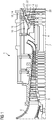
- FIG. 2 shows one of the two Silobrennhuntn 10 of the gas turbine 1 in cross section.
- the gas turbine 1 in the exemplary embodiment comprises two such Silobrennhuntn 10, which are arranged on both sides of the gas turbine 1 standing over a deflection 32.
- the arrangement of the other, not shown Silobrennhunt 10 is correspondingly mirror-symmetrical.
- the silo separation chambers 10 z. B. also be arranged in a boxer arrangement.
- the silo combustion chamber 10 has a circular cylindrical basic shape. It consists of a straight, circular cylinder jacket-shaped flame tube 34, which is open at its lower base 36 down and there merges into the deflection 32, which communicates with the turbine 12. On the upper base surface 38, which is also referred to as the combustion chamber bottom, a plurality of burners 40 are arranged, with their flame direction parallel to the axis 42 of the flame tube 34 facing downward.
- the flame tube 34 is concentrically surrounded by a thus likewise circular cylindrical jacket 44.
- the sheath 44 also extends around the deflection 32, but it always maintains a distance from the deflection 32 and the flame tube 34, so that - with the inclusion of the deflection 32 - obliquely cylindrical jacket-shaped gap 45 results.
- the jacket 44 transitions into a shield-shaped cover 46, which closes off the interior of the flame tube 34 around the burners 40.
- the described gap 45 communicates with the outlet of the compressor 8 of the gas turbine 1. In the gap 45 therefore flows during operation of the gas turbine 1 compressed air flowing along the entire circumference of the deflection 32 and the flame tube 34 into the space surrounding the burner 40 and burned there with the fuel.
- the hot gases generated in the burner flames in the burner tube 34 pass through the interior of the deflection 32 into the turbine 12.
- the compressed air does not reach directly into the space surrounding the burner 40, but only through a heat exchanger, not shown.
- the gas turbine 1 in the embodiment is in fact equipped for a heat recuperation.
- d. H. Axial center of the flame tube 34 is in the outer side of the casing 44 respectively on two opposite sides of withdrawal lines 50 introduced, in which the compressor air flows.
- the compressor air from the extraction lines 50 is then passed to the heat exchanger, not shown, where it is heated by means of the exhaust gas of the gas turbine 1. Subsequently, it is passed to the burners 40 via a supply line 52 communicating with the rear space of the burner 40 and located in the axis of the silo combustion chamber. Due to the recuperation in the heat exchanger can in combination with wet compression, d. H. the injection of water into the intake air stream of the compressor 8 an efficiency increase of up to 8.5% can be achieved.
- the described solution can also be retrofitted to existing systems.
- the attachment location of the extraction lines 50 results, on the one hand, from the desire to have as cool as possible compressor air to the heat exchanger on the other hand, also for structural reasons, since pipes of size DN500 or DN 700 are used to keep the pressure loss in the heat exchanger system as low as possible.
- the exposed to the hot gas flame tube 42 is subject during operation of the gas turbine 1 high thermal loads, as higher temperatures mean better efficiency.
- the flame tube is therefore provided with lining heat shield bricks 54, which are arranged in superimposed, annular stone rows. However, these must be cooled, which happens on the one hand by convective cooling through the air flowing in the gap 45 compressor air, on the other hand by direct impingement cooling by cooling holes 56, which are introduced in large numbers in the entire flame tube 34. Compressor air flows through the cooling holes onto the heat shield blocks 54 and cools them.
- the extraction lines 50 represent pressure sinks, so that the compressed air flows from the compressor outlet with the largest mass flow through these pipes. This reduces the amount of cooling air of the heat shield blocks 54 lying above the extraction lines 50, so that the cooling can be insufficient here.
- tap lines 58 are provided, which are placed at the height of the top row of stones, ie practically directly adjacent to the seal 48 in the upper axial end portion of the gap 45 in the casing 44 and communicate with the gap 45.
- a tapping line 58 located above the withdrawal line 50 is provided, which opens into the respective withdrawal line 50.
- the tap lines 58 have a substantially smaller diameter than the sampling lines 50.
- tapping lines 58 By means of these tapping lines 58, part of the air flows past the respective outlet line 50 at the junction and into the tapping lines 58, so that a forced flow is generated for the upper rows of stones, by means of which they are cooled.
- the entire system is designed so that sufficient cooling flow is created.
- measures are taken which have a correspondingly lower pressure loss in the tapping lines 58 than in the section 60 between inlet of the withdrawal line 50 and the mouth of the tapping lines 58 into the withdrawal line 50 to reach.
- the inlet of the extraction line 50 can be made sharp-edged, but the tapping line 58 rounded.
- the section 60 between the inlet of the extraction line 50 and the mouth of the tap lines 58 are provided in the extraction line 50 orifices.
Landscapes
- Engineering & Computer Science (AREA)
- Chemical & Material Sciences (AREA)
- Combustion & Propulsion (AREA)
- Mechanical Engineering (AREA)
- General Engineering & Computer Science (AREA)
- Turbine Rotor Nozzle Sealing (AREA)
- Heat-Exchange Devices With Radiators And Conduit Assemblies (AREA)
Description
- Die Erfindung betrifft eine Silobrennkammer für eine Gasturbine, umfassend ein zylindrisches Flammrohr, welches auf seiner Außenseite unter Bildung eines Spaltes mit einer zylindrischen Ummantelung versehen ist, wobei eine erste Grundfläche des Flammrohrs einen Brenner aufweist und die zweite Grundfläche des Flammrohrs eine mit dem Turbineneintritt der Gasturbine verbindbare Öffnung aufweist, wobei die Ummantelung in einem axialen Mittelbereich eine Entnahmeleitung zur Entnahme von Luft aus dem Spalt aufweist.
- Eine Gasturbine ist eine Strömungsmaschine, in der ein unter Druck stehendes Gas expandiert. Sie besteht aus einer Turbine oder Expander, einem vorgeschalteten Verdichter und einer zwischengeschalteten Brennkammer. Das Wirkungsprinzip beruht auf dem Kreisprozess (Joule-Prozess): Dieser komprimiert über die Beschaufelung einer oder mehrerer Verdichterstufen Luft, mischt diese anschließend in der Brennkammer mit einem gasförmigen oder flüssigen Treibstoff, zündet und verbrennt.
- So entsteht ein Heißgas (Mischung aus Verbrennungsgas und Luft), das im nachfolgenden Turbinenteil entspannt, wobei sich thermische in mechanische Energie umwandelt und zunächst den Verdichter antreibt. Der verbleibende Anteil wird beim Wellentriebwerk zum Antrieb eines Generators, eines Propellers oder anderen rotierenden Verbrauchern verwendet. Beim Strahltriebwerk dagegen beschleunigt die thermische Energie den heißen Gasstrom, was den Schub erzeugt.
- Neben den häufig eingesetzten Ring- oder Rohrbrennkammern werden Gasturbinen auch mit so genannten Silobrennkammern ausgestattet. Diese sind vergleichsweise groß ausgebildet und umfassen ein zylindrisches Flammrohr, welches auf der Außenseite unter Bildung eines Spaltes mit einer zylindrischen Ummantelung versehen ist. Die im Verdichter verdichtete Luft strömt durch den Spalt zum Boden der Silobrennkammer, der eine Grundfläche des Zylinders bildet und an dem die Brenner angeordnet sind. Hier wird die Luft zur Verbrennung genutzt und das im Innenraum des Flammrohrs entstandene Heißgas wird durch eine Öffnung in der anderen Grundfläche des Zylinders zum Turbineneintritt geleitet.
- Zur Erhöhung des Wirkungsgrades der Gasturbine ist es bekannt, diese mit einem Wärmetauscher (Rekuperator) auszustatten, der das Abgas der Turbine dazu nutzt, die im Verdichter komprimierte Luft vor ihrer Zuführung zu den Brennern vorzuwärmen. Hierzu werden bei Silobrennkammern seitlich an der Ummantelung des Flammrohrs Entnahmeleitungen für die Luft angeordnet, mittels derer die vom Verdichter in den Spalt strömende Luft entnommen und dem Wärmetauscher zugeführt werden kann. Hierbei hat sich herausgestellt, dass es von Vorteil ist, die Entnahmeleitungen in Richtung der Achse der zylindrischen Silobrennkammer etwa mittig anzuordnen, da bei weiter in Richtung der Brenner angeordneten Entnahmeleitungen einerseits Bauraumprobleme auftreten können, andererseits die Verdichterluft beim weiteren Strömen durch den Spalt zu weit erwärmt wird. Für einen möglichst hohen Wirkungsgrad des Wärmetauschers sollte nämlich der Temperaturunterschied zwischen Verdichterluft und Abgas der Gasturbine möglichst groß sein.
- Bei derartigen mittig angeordneten Entnahmeleitungen ergibt sich jedoch das Problem, dass die Kühlung des Flammrohres im Bereich nahe des Silobrennkammerbodens, d. h. in Richtung zu den Brennern hin, nicht ausreichend sein kann. Das Flammrohr ist hier mit Hitzeschildsteinen ausgekleidet. Werden deren Halter nicht ausreichend gekühlt, kann es zum Steinabwurf und einem dadurch verursachten Turbinenschaden kommen.
- Es ist daher Aufgabe der Erfindung, eine Silobrennkammer der eingangs genannten Art anzugeben, die einerseits einen besonders hohen Wirkungsgrad der Gasturbine durch Nutzung eines Wärmetauschers ermöglicht und andererseits eine besonders lange Lebensdauer aufweist.
- Diese Aufgabe wird erfindungsgemäß gelöst, indem die Ummantelung in einem der erste Grundfläche zugeordneten axialen Endbereich eine Anzapfleitung aufweist, die in die Entnahmeleitung mündet.
- Die Erfindung ist eine Silobrennkammer gemäß dem Anspruch 1.
- Das Dokument
US2009/0180873 offenbart eine Silobrennkammer gemäß dem Oberbegriff des Anspruchs 1. - Die Erfindung geht dabei von der Überlegung aus, dass die Kühlung im dem Brenner zugewandten axialen Endbereich der Silobrennkammer durch die verringerte Kühlluftmenge erzeugt wird, die in Folge der Entnahme der Verdichterluft dort entsteht. Zwar ist der statische Druck in diesem Bereich noch immer hoch, jedoch der Luftmassenstrom geringer, so dass die dortigen Bauteile schlechter konvektiv gekühlt werden. Daher sollte die konvektive Flammrohrkühlung verbessert werden, indem der Luftmassenstrom im Spalt zwischen Entnahmeleitung und Silobrennkammerboden erhöht wird. Hierzu sind im Bereich des Silobrennkammerbodens Anzapfleitungen (Bleedleitungen) angeordnet, die zur Entnahmeleitung führen. Diese erzeugen eine Art Zwangsströmung, die sicherstellt, dass ein gewisser Luftmassenstrom am kompletten Flammrohr vorbei gelangt und erst über die Anzapfleitung in die zum Wärmetauscher führende Entnahmeleitung gelangt.
- Vorteilhafterweise ist dabei eine Mehrzahl gleichartiger Entnahmeleitungen in regelmäßigem Abstand entlang des Umfangs der Ummantelung angeordnet, wobei die Ummantelung für jede der Entnahmeleitungen in einem der ersten Grundfläche zugeordneten axialen Endbereich eine Anzapfleitung aufweist, die in die jeweilige Entnahmeleitung mündet. Die Entnahmeleitungen sind also z. B. sternförmig um die gesamte Silobrennkammer herum angeordnet, oder es sind nur zwei Entnahmeleitungen gegenüberliegend angeordnet. In jedem Fall ist für jede Entnahmeleitung eine Anzapfleitung vorgesehen, die in beschriebener Weise den Luftmassenstrom im dem Silobrennkammerboden zugewandten Bereich des Spaltes zwischen Flammrohr und Ummantelung sicherstellt.
- Die jeweilige Anzapfleitung weist dabei vorzugsweise einen geringeren Innendurchmesser auf als die jeweilige Entnahmeleitung. Die Entnahmeleitungen sind nämlich vorteilhaft vergleichsweise groß ausgebildet, um die Druckverluste in diesen Leitungen gering zu halten. Zu große Druckverluste im Rekuperatorsystem vergrößern nämlich automatisch den Brennkammerdruckverlust und erhöhen als Ergebnis den Kühlluftverbrauch der Brennkammer. Dies hat negative Einflüsse auf den Wirkungsgrad der Anlage. Vorzugsweise werden hier Leitungen größer als DN500, besser größer als DN 700 eingesetzt. Die Anzapfleitungen müssen hingegen nur gerade so groß gewählt sein, dass noch ein ausreichender Luftstrom zur konvektiven Kühlung an den jenseits der Entnahmeleitung liegenden Bereichen des Flammrohrs anliegt. Je geringer hier der Luftmassenstrom ist, desto geringer bleibt auch die Temperatur der dem Wärmetauscher zugeführten Luft, was positiv hinsichtlich dessen Wirkungsgrades ist. Daher können diese Anzapfleitungen kleiner dimensioniert sein.
- Vorteilhafterweise sind die jeweilige Anzapfleitung und der Abschnitt der jeweiligen Entnahmeleitung zwischen Ummantelung und Mündung der Anzapfleitung derart ausgebildet, dass die Anzapfleitung einen geringeren Druckverlust erzeugt als der Abschnitt der jeweiligen Entnahmeleitung. Hierdurch wird erreicht, dass sich die gewünschte Kühlströmung auch sicher einstellt, d. h. ein ausreichender Teil der Luft tatsächlich durch die Anzapfleitung und nicht nur direkt durch die Entnahmeleitung strömt. Der Unterschied hinsichtlich des Druckverlusts kann bei der Auslegung hinsichtlich des benötigten Kühlbedarfs eingestellt werden.
- Eine erste vorteilhafte Umsetzung dieses Druckverlustunterschiedes kann dadurch realisiert sein, dass der Übergang zwischen Ummantelung und jeweiliger Anzapfleitung abgerundet ist. Dies führt zu geringen Druckverlusten am Eintritt der Anzapfleitung.
- Entsprechend sollte vorteilhafterweise der Übergang zwischen Ummantelung und jeweiliger Entnahmeleitung scharfkantig sein, so dass hier die Eintrittsdruckverluste direkt in die Entnahmeleitung entsprechend hoch sind. Durch die vorgenannten Maßnahmen kann bereits durch die Eintrittsdruckverluste der Anzapf- bzw. Entnahmeleitung ein ausreichend hoher Druckverlustunterschied gewährleistet sein, so dass sich die gewünschte Zwangsströmung zur konvektiven Kühlung an den jenseits der Entnahmeleitung liegenden Bereichen des Flammrohrs einstellt.
- Sollte der Eintrittsdruckverlustunterschied hierzu allein nicht ausreichend sein, kann alternativ oder zusätzlich der Abschnitt der jeweiligen Entnahmeleitung zwischen Eintritt und Mündung der Anzapfleitung eine oder mehrere Blenden aufweisen. Hierdurch wird ebenfalls der Druckverlust für das direkte Einströmen in die Entnahmeleitung erhöht.
- Eine Gasturbine umfasst vorteilhafterweise eine beschriebene Silobrennkammer.
- Die beschriebene Entnahmeleitung führt dabei vorteilhafterweise zu einem Wärmetauscher, in dem die entnommene Luft mittels der Abgaswärme der Gasturbine vorgewärmt wird. Hierzu bildet die entnommene Luft einen ersten Fluidstrom und das Abgas der Gasturbine den zweiten Fluidstrom im Wärmetauscher. Die erwärmte Luft wird anschließend im Bereich der Brenner wieder eingeführt und dort zur Verbrennung des Treibstoffs in den Brennern im Flammrohr genutzt.
- Der Spalt in der Silobrennkammer ist dazu vorteilhafterweise zur ersten Grundfläche, d. h. zum Brennkammerboden mit den Brennern hin abgedichtet, so dass die Verdichterluft ausschließlich entweder durch vorgesehene Kühlbohrungen oder über den Wärmetauscher in das Flammrohr strömen kann.
- Die mit der Erfindung erzielten Vorteile bestehen insbesondere darin, dass durch die Anbringung von Anzapfleitungen aus dem Bereich zwischen Luftentnahme und Brennkammerboden eine ausreichende Kühlung des Flammrohres erreicht wird. Dadurch wird eine Nutzung der Rekuperation in Gasturbinen mit Silobrennkammern ermöglicht, wodurch eine Verbesserung des thermodynamischen Gasturbinenwirkungsgrades um ca. 8,5 % erreicht werden kann. Die Anordnung eines Wärmetauschers ist auch vergleichsweise günstig gegenüber einer kombinierten Gas- und Dampfturbinenlösung und vergleichsweise einfach nachrüstbar.
- Ein Ausführungsbeispiel der Erfindung wird anhand einer Zeichnung näher erläutert. Darin zeigen
- FIG 1
- einen teilweisen Längsschnitt durch eine Gasturbine und
- FIG 2
- einen Querschnitt durch die Silobrennkammer der Gasturbine.
- Gleiche Teile sind in allen Figuren mit denselben Bezugszeichen versehen.
- Die
FIG 1 zeigt eine Gasturbine 1 in einem Längsteilschnitt. Der Teilschnitt zeigt nur die obere Hälfte der Gasturbine 1. Die Gasturbine 1 weist im Inneren einen um eine Rotationsachse 2 (Axialrichtung) drehgelagerten Rotor 4 auf, der auch als Turbinenläufer bezeichnet wird. Entlang des Rotors 4 folgen aufeinander zunächst ein Ansauggehäuse 6 und ein Verdichter 8. Aus dem Austritt des Verdichters 8 wird die Luft in zwei inFIG 1 nur im Ansatz dargestellte Silobrennkammern 10 geführt, die inFIG 2 näher dargestellt sind. Auf die Silobrennkammer 10 folgen eine Turbine 12 und das nicht mehr dargestellte Abgasgehäuse. - Die Silobrennkammern 10 kommunizieren mit einem ringförmigen Heißgaskanal 14 in der Turbine 12. Dort bilden beispielsweise vier hintereinander geschaltete Turbinenstufen 16 die Turbine 12. Jede Turbinenstufe 16 ist aus zwei Schaufelringen gebildet. In Strömungsrichtung eines Arbeitsmediums gesehen folgt im Heißgaskanal 14 einer aus Leitschaufelreihe 18 eine aus Laufschaufeln 20 gebildete Laufschaufelreihe 22. Die Schaufeln Leitschaufeln 24 der Leitschaufelreihe 18 und die Laufschaufeln 20 sind leicht gekrümmt profiliert, ähnlich einer Flugzeugtragfläche.
- Die Leitschaufeln 24 sind dabei am Stator 26 befestigt. Jede Leitschaufel 24 weist neben dem eigentlichen Schaufelblatt einen auch als Plattform bezeichneten Leitschaufelfuß und einen dem Leitschaufelfuß gegenüberliegenden Leitschaufelkopf auf. Der Leitschaufelkopf ist dem Rotor 4 zugewandt und an einem Innenring 30 festgelegt. Jeder Innenring 30 umschließt dabei die Welle des Rotors 4. Ebenso weist jede Laufschaufel 20 einen derartigen Laufschaufelfuß auf, endet jedoch in einer Laufschaufelspitze.
- Die Laufschaufeln 18 einer Laufschaufelreihe 22 sind mittels jeweils einer Turbinenscheibe 28 am Rotor 4 angebracht. Die Laufschaufeln 20 bilden somit Bestandteile des Rotors oder Läufers 4. An den Rotor 4 angekoppelt ist ein Generator oder eine Arbeitsmaschine (nicht dargestellt).
- Während des Betriebes der Gasturbine 1 wird vom Verdichter 8 durch das Ansauggehäuse 6 Luft angesaugt und verdichtet. Die am turbinenseitigen Ende des Verdichters 8 bereitgestellte verdichtete Luft wird in die Silobrennkammern 10 geführt, was in
FIG 2 noch näher erläutert wird, und dort mit einem Brennmittel vermischt. Das Gemisch wird dann unter Bildung eines Heißgases in den Silobrennkammern 10 verbrannt. Von dort aus strömt das Heißgas entlang des Heißgaskanals 14 vorbei an den Leitschaufeln 24 und den Laufschaufeln 20. - Dem Fluidstrom wird durch die möglichst wirbelfreie laminare Umströmung der Turbinenschaufeln 20, 24 ein Teil seiner inneren Energie entzogen, der auf die Laufschaufeln 20 der Turbine 12 übergeht. Über diese wird dann der Rotor 4 in Drehung versetzt, wodurch zunächst der Verdichter 8 angetrieben wird. Die nutzbare Leistung wird an die nicht dargestellte Arbeitsmaschine abgegeben.
-
FIG 2 zeigt eine der beiden Silobrennkammern 10 der Gasturbine 1 im Querschnitt. Die Gasturbine 1 im Ausführungsbeispiel umfasst zwei solcher Silobrennkammern 10, die beiderseitig der Gasturbine 1 stehend über eine Umlenkung 32 angeordnet sind. Die Anordnung der anderen, nicht dargestellten Silobrennkammer 10 ist entsprechend spiegelsymmetrisch. Alternativ können die Silobrennkammern 10 z. B. auch in einer Boxeranordnung angeordnet sein. - Die Silobrennkammer 10 weist eine kreiszylindrische Grundform auf. Sie besteht aus einem geraden, kreiszylindermantelförmigen Flammrohr 34, welches an seiner unteren Grundfläche 36 nach unten geöffnet ist und dort in die Umlenkung 32 übergeht, die mit der Turbine 12 kommuniziert. Auf der oberen Grundfläche 38, die auch als Brennkammerboden bezeichnet wird, sind mehrere Brenner 40 angeordnet, wobei deren Flammrichtung parallel zur Achse 42 des Flammrohrs 34 nach unten weist.
- Das Flammrohr 34 ist konzentrisch von einer somit ebenfalls kreiszylindermantelförmigen Ummantelung 44 umgeben. Die Ummantelung 44 erstreckt sich auch um die Umlenkung 32, wobei sie jedoch stets einen Abstand zur Umlenkung 32 und zum Flammrohr 34 einhält, so dass sich ein - unter Einbeziehung der Umlenkung 32 - schief zylindermantelförmiger Spalt 45 ergibt. Die Ummantelung 44 geht im Bereich des Brennkammerbodens in eine schildförmige Abdeckung 46 über, die um die Brenner 40 herum den Innenraum des Flammrohrs 34 abschließt. Der beschriebene Spalt 45 kommuniziert mit dem Austritt des Verdichters 8 der Gasturbine 1. In dem Spalt 45 strömt daher im Betrieb der Gasturbine 1 verdichtete Luft, die entlang des gesamten Umfangs der Umlenkung 32 und des Flammrohrs 34 bis in den die Brenner 40 umgebenden Raum strömt und dort mit dem Brennstoff verbrannt wird. Die in den Brennerflammen im Flammrohr 34 erzeugten Heißgase gelangen durch den Innenraum der Umlenkung 32 dann in die Turbine 12.
- Die verdichtete Luft gelangt jedoch nicht direkt in den die Brenner 40 umgebenden Raum, sondern erst durch einen nicht näher dargestellten Wärmetauscher. Die Gasturbine 1 im Ausführungsbeispiel ist nämlich für eine Wärmerekuperation ausgerüstet. Hierzu ist zunächst der Spalt 45 in der Ebene des Brennkammerbodens, d. h. in der oberen Grundfläche 38 gegen den Raum um die Brenner 40 herum mittels einer ringförmigen Abdichtung 48 gasdicht abgetrennt. In der vertikalen, d. h. axialen Mitte des Flammrohres 34 ist in die Außenseite der Ummantelung 44 jeweils an zwei gegenüberliegenden Seiten Entnahmeleitungen 50 eingebracht, in die die Verdichterluft strömt.
- Die Verdichterluft aus den Entnahmeleitungen 50 wird sodann zu dem nicht näher dargestellten Wärmetauscher geführt, wo sie mittels der Abgasluft der Gasturbine 1 erwärmt wird. Anschließend wird sie über eine in der Achse der Silobrennkammer liegende, mit dem Rückraum der Brenner 40 kommunizierende Zuführleitung 52 zu den Brennern 40 geleitet. Durch die Rekuperation im Wärmetauscher kann in Kombination mit Wet Compression, d. h. dem Eindüsen von Wasser in den Ansaugluftstrom des Verdichters 8 eine Wirkungsgradsteigerung von bis zu 8,5 % erreicht werden. Die beschriebene Lösung kann auch bei bestehenden Anlagen nachgerüstet werden.
- Der Anbringort der Entnahmeleitungen 50 ergibt sich zum einen aus dem Wunsch, noch möglichst kühle Verdichterluft zum Wärmetauscher zu führen, um hier einen möglichst hohen Wirkungsgrad zu erzielen, zum anderen auch aus baulichen Gegebenheiten, da hier Rohre der Größe DN500 oder DN 700 verwendet werden, um den Druckverlust im Wärmetauschersystem möglichst gering zu halten.
- Das dem heißen Gas ausgesetzte Flammrohr 42 unterliegt während des Betriebes der Gasturbine 1 hohen thermischen Belastungen, da höhere Temperaturen einen besseren Wirkungsgrad bedeuten. Das Flammrohr ist daher mit auskleidenden Hitzeschildsteinen 54 versehen, die in übereinander liegenden, ringförmigen Steinreihen angeordnet sind. Diese müssen jedoch gekühlt werden, was einerseits durch konvektive Kühlung durch die im Spalt 45 strömende Verdichterluft geschieht, andererseits durch direkte Prallkühlung mittels Kühlbohrungen 56, die in großer Anzahl in das gesamte Flammrohr 34 eingebracht sind. Durch die Kühlbohrungen strömt Verdichterluft auf die Hitzeschildsteine 54 und kühlt diese.
- Problematisch ist hierbei jedoch, dass die Entnahmeleitungen 50 Drucksenken darstellen, so dass die verdichtete Luft vom Verdichteraustritt mit dem größten Massenstrom durch diese Rohrleitungen strömt. Dadurch verringert sich die Kühlluftmenge der oberhalb der Entnahmeleitungen 50 liegenden Hitzeschildsteine 54, so dass die Kühlung hier ungenügend sein kann.
- Daher sind Anzapfleitungen 58 vorgesehen, die auf der Höhe der obersten Steinreihe, d. h. praktisch direkt angrenzend an die Abdichtung 48 im oberen axialen Endbereich des Spaltes 45 in die Ummantelung 44 eingebracht sind und mit dem Spalt 45 kommunizieren. Für jede Entnahmeleitung 50 ist eine oberhalb der Entnahmeleitung 50 liegende Anzapfleitung 58 vorgesehen, die in die jeweilige Entnahmeleitung 50 mündet. Die Anzapfleitungen 58 haben dabei einen wesentlich geringeren Durchmesser als die Entnahmeleitungen 50.
- Durch diese Anzapfleitungen 58 strömt ein Teil der Luft an der Einmündung zur jeweiligen Entnahmeleitung 50 vorbei und in die Anzapfleitungen 58, so dass für die oberen Steinreihen eine Zwangsströmung erzeugt wird, mittels derer diese gekühlt werden. Das gesamte System ist dabei so ausgelegt, dass eine ausreichende Kühlströmung entsteht.
- Diese Auslegung umfasst einerseits den Innendurchmesser der Anzapfleitungen 58 im Verhältnis zu dem der Entnahmeleitungen 50. Andererseits sind Maßnahmen getroffen, die einen entsprechend geringeren Druckverlust in den Anzapfleitungen 58 als im Abschnitt 60 zwischen Eintritt der Entnahmeleitung 50 und der Mündung der Anzapfleitungen 58 in die Entnahmeleitung 50 erreichen. Dazu kann der Eintritt der Entnahmeleitung 50 scharfkantig ausgeführt sein, der der Anzapfleitung 58 jedoch abgerundet. Zusätzlich können in dem Abschnitt 60 zwischen Eintritt der Entnahmeleitung 50 und der Mündung der Anzapfleitungen 58 in die Entnahmeleitung 50 Blenden vorgesehen sein.
Claims (10)
- Silobrennkammer (10) für eine Gasturbine (1), umfassend ein zylindrisches Flammrohr (34), welches auf seiner Außenseite unter Bildung eines Spaltes (45) mit einer zylindrischen Ummantelung (44) versehen ist, wobei eine erste Grundfläche (38) des Flammrohrs (34) einen Brenner (40) aufweist und die zweite Grundfläche (36) des Flammrohrs (34) eine mit dem Turbineneintritt der Gasturbine (1) verbindbare Öffnung aufweist, dadurch gekennzeichnet, dass die Ummantelung (44) in einem axialen Mittelbereich eine Entnahmeleitung (50) zur Entnahme von Luft aus dem Spalt (45) aufweist, und wobei die Ummantelung (44) in einem der ersten Grundfläche (38) zugeordneten axialen Endbereich eine Anzapfleitung (58) aufweist, die in die Entnahmeleitung (50) mündet.
- Silobrennkammer (10) nach Anspruch 1, bei der eine Mehrzahl gleichartiger Entnahmeleitungen (50) in regelmäßigem Abstand entlang des Umfangs der Ummantelung (44) angeordnet ist, wobei die Ummantelung (44) für jede der Entnahmeleitungen (50) in einem der ersten Grundfläche (38) zugeordneten axialen Endbereich eine Anzapfleitung (58) aufweist, die in die jeweilige Entnahmeleitung (50) mündet.
- Silobrennkammer (10) nach einem der vorhergehenden Ansprüche, bei der die jeweilige Anzapfleitung (58) einen geringeren Innendurchmesser aufweist als die jeweilige Entnahmeleitung (50).
- Silobrennkammer (10) nach einem der vorhergehenden Ansprüche, bei der die jeweilige Anzapfleitung (58) und der Abschnitt (60) der jeweiligen Entnahmeleitung (50) zwischen Ummantelung (44) und Mündung der Anzapfleitung (58) derart ausgebildet sind, dass die Anzapfleitung (58) einen geringeren Druckverlust erzeugt als der Abschnitt (60) der jeweiligen Entnahmeleitung (50).
- Silobrennkammer (10) nach Anspruch 4, bei der der Übergang zwischen Ummantelung (44) und jeweiliger Anzapfleitung (58) abgerundet ist.
- Silobrennkammer (10) nach Anspruch 4 oder 5, bei der der Übergang zwischen Ummantelung (44) und jeweiliger Entnahmeleitung (50) scharfkantig ist.
- Silobrennkammer (10) nach einem der Ansprüche 4 bis 6, bei der der Abschnitt (60) der jeweiligen Entnahmeleitung (50) eine Blende aufweist.
- Gasturbine (1) mit einer Silobrennkammer (10) nach einem der vorhergehenden Ansprüche.
- Gasturbine (1) nach Anspruch 8, bei der die Entnahmeleitung (50) zu einem Wärmetauscher führt, in dem die entnommene Luft mittels der Abgaswärme der Gasturbine (1) vorgewärmt wird.
- Gasturbine (1) nach Anspruch 8 und 9, in deren Silobrennkammer (10) der Spalt (45) zur ersten Grundfläche (38) hin abgedichtet ist.
Priority Applications (3)
| Application Number | Priority Date | Filing Date | Title |
|---|---|---|---|
| EP14152042.9A EP2899464B1 (de) | 2014-01-22 | 2014-01-22 | Silobrennkammer für eine Gasturbine |
| PCT/EP2015/050482 WO2015110316A1 (de) | 2014-01-22 | 2015-01-13 | Silobrennkammer für eine gasturbine |
| EP15700658.6A EP3069080A1 (de) | 2014-01-22 | 2015-01-13 | Silobrennkammer für eine gasturbine |
Applications Claiming Priority (1)
| Application Number | Priority Date | Filing Date | Title |
|---|---|---|---|
| EP14152042.9A EP2899464B1 (de) | 2014-01-22 | 2014-01-22 | Silobrennkammer für eine Gasturbine |
Publications (2)
| Publication Number | Publication Date |
|---|---|
| EP2899464A1 EP2899464A1 (de) | 2015-07-29 |
| EP2899464B1 true EP2899464B1 (de) | 2017-01-11 |
Family
ID=50072859
Family Applications (2)
| Application Number | Title | Priority Date | Filing Date |
|---|---|---|---|
| EP14152042.9A Not-in-force EP2899464B1 (de) | 2014-01-22 | 2014-01-22 | Silobrennkammer für eine Gasturbine |
| EP15700658.6A Withdrawn EP3069080A1 (de) | 2014-01-22 | 2015-01-13 | Silobrennkammer für eine gasturbine |
Family Applications After (1)
| Application Number | Title | Priority Date | Filing Date |
|---|---|---|---|
| EP15700658.6A Withdrawn EP3069080A1 (de) | 2014-01-22 | 2015-01-13 | Silobrennkammer für eine gasturbine |
Country Status (2)
| Country | Link |
|---|---|
| EP (2) | EP2899464B1 (de) |
| WO (1) | WO2015110316A1 (de) |
Family Cites Families (6)
| Publication number | Priority date | Publication date | Assignee | Title |
|---|---|---|---|---|
| US4458481A (en) * | 1982-03-15 | 1984-07-10 | Brown Boveri Turbomachinery, Inc. | Combustor for regenerative open cycle gas turbine system |
| GB8914825D0 (en) * | 1989-06-28 | 1989-08-16 | Rolls Royce Plc | Gas turbine engine power unit |
| JPH09329335A (ja) * | 1996-06-11 | 1997-12-22 | Hitachi Ltd | 再生型ガスタービン燃焼器 |
| JP2000008881A (ja) * | 1998-06-23 | 2000-01-11 | Toshiba Corp | ガスタービンプラント |
| JP2001107748A (ja) * | 1999-10-07 | 2001-04-17 | Toshiba Corp | ガスタービンプラント |
| EP1865258A1 (de) * | 2006-06-06 | 2007-12-12 | Siemens Aktiengesellschaft | Gepanzerte Maschinenkomponente und Gasturbine |
-
2014
- 2014-01-22 EP EP14152042.9A patent/EP2899464B1/de not_active Not-in-force
-
2015
- 2015-01-13 WO PCT/EP2015/050482 patent/WO2015110316A1/de not_active Ceased
- 2015-01-13 EP EP15700658.6A patent/EP3069080A1/de not_active Withdrawn
Non-Patent Citations (1)
| Title |
|---|
| None * |
Also Published As
| Publication number | Publication date |
|---|---|
| EP3069080A1 (de) | 2016-09-21 |
| WO2015110316A1 (de) | 2015-07-30 |
| EP2899464A1 (de) | 2015-07-29 |
Similar Documents
| Publication | Publication Date | Title |
|---|---|---|
| DE60221558T2 (de) | Turbinenmotor mit luftgekühlter turbine | |
| DE102014100242B4 (de) | Überleitungskanal mit verbesserter Kühlung für eine Turbomaschine | |
| CH708325A2 (de) | Mantelringblocksegment für eine Gasturbine. | |
| EP1418319A1 (de) | Gasturbine | |
| DE10009655C1 (de) | Kühlluftsystem | |
| DE102010036524A1 (de) | Vorrichtung und Verfahren für eine Gasturbinendüse | |
| CH708780A2 (de) | Übergangskanalanordnung mit modifizierter Hinterkante in einem Turbinensystem. | |
| EP2634381A1 (de) | Gasturbine mit einem Abgas-Diffusor und Stützrippen | |
| DE102009003702A1 (de) | Wiedererwärmungsbrennkammer für eine Gasturbine | |
| CH710052A2 (de) | Brennkammerkappenanordnung, Brennkammer und Gasturbine. | |
| EP3064706A1 (de) | Leitschaufelreihe für eine axial durchströmte Strömungsmaschine | |
| CH707899A2 (de) | Turbomaschine mit Kühlstruktur. | |
| DE102012100660A1 (de) | Turbinenschaufel zur Verwendung in Gasturbinen und Verfahren zur Herstellung derselben | |
| CH709266B1 (de) | Turbinenschaufel und Verfahren zum Auswuchten eines Spitzendeckbandes einer Turbinenschaufel und Gasturbine. | |
| EP2987967B1 (de) | Verdichtergehäuse für eine Gasturbine | |
| EP2327933A1 (de) | Brenneranordnung | |
| CH709047A2 (de) | Turbinenschaufel und Verfahren zur Kühlung einer Turbinenschaufel einer Gasturbine. | |
| DE102011054667A1 (de) | System und Verfahren zur Kühlung einer Düse | |
| EP2823154A1 (de) | Eine in eine hohle, gekühlte turbinenschaufel einsetzbare kühlmittelüberbrückungsleitung für eine gasturbine | |
| DE102014117568A1 (de) | Verdichterauslassgehäuseanordnung | |
| WO2017025284A1 (de) | Brennkammer für eine gasturbine und hitzeschildelement zum auskleiden einer derartigen brennkammer | |
| DE102011054669A1 (de) | System und Verfahren zur Kühlung einer Düse | |
| CH703865A2 (de) | Brennkammereinrichtung sowie Verfahren zu deren Betrieb. | |
| DE102014118697A1 (de) | Turbinenleitapparat und Verfahren zum Kühlen eines Turbinenleitapparats einer Gasturbine | |
| EP2899464A1 (de) | Silobrennkammer für eine Gasturbine |
Legal Events
| Date | Code | Title | Description |
|---|---|---|---|
| PUAI | Public reference made under article 153(3) epc to a published international application that has entered the european phase |
Free format text: ORIGINAL CODE: 0009012 |
|
| 17P | Request for examination filed |
Effective date: 20140122 |
|
| AK | Designated contracting states |
Kind code of ref document: A1 Designated state(s): AL AT BE BG CH CY CZ DE DK EE ES FI FR GB GR HR HU IE IS IT LI LT LU LV MC MK MT NL NO PL PT RO RS SE SI SK SM TR |
|
| AX | Request for extension of the european patent |
Extension state: BA ME |
|
| 17P | Request for examination filed |
Effective date: 20160120 |
|
| RBV | Designated contracting states (corrected) |
Designated state(s): AL AT BE BG CH CY CZ DE DK EE ES FI FR GB GR HR HU IE IS IT LI LT LU LV MC MK MT NL NO PL PT RO RS SE SI SK SM TR |
|
| GRAP | Despatch of communication of intention to grant a patent |
Free format text: ORIGINAL CODE: EPIDOSNIGR1 |
|
| INTG | Intention to grant announced |
Effective date: 20160808 |
|
| GRAS | Grant fee paid |
Free format text: ORIGINAL CODE: EPIDOSNIGR3 |
|
| GRAA | (expected) grant |
Free format text: ORIGINAL CODE: 0009210 |
|
| AK | Designated contracting states |
Kind code of ref document: B1 Designated state(s): AL AT BE BG CH CY CZ DE DK EE ES FI FR GB GR HR HU IE IS IT LI LT LU LV MC MK MT NL NO PL PT RO RS SE SI SK SM TR |
|
| REG | Reference to a national code |
Ref country code: GB Ref legal event code: FG4D Free format text: NOT ENGLISH |
|
| REG | Reference to a national code |
Ref country code: CH Ref legal event code: EP |
|
| REG | Reference to a national code |
Ref country code: AT Ref legal event code: REF Ref document number: 861651 Country of ref document: AT Kind code of ref document: T Effective date: 20170115 |
|
| REG | Reference to a national code |
Ref country code: IE Ref legal event code: FG4D Free format text: LANGUAGE OF EP DOCUMENT: GERMAN |
|
| REG | Reference to a national code |
Ref country code: DE Ref legal event code: R096 Ref document number: 502014002436 Country of ref document: DE |
|
| PGFP | Annual fee paid to national office [announced via postgrant information from national office to epo] |
Ref country code: DE Payment date: 20170320 Year of fee payment: 4 |
|
| REG | Reference to a national code |
Ref country code: LT Ref legal event code: MG4D |
|
| REG | Reference to a national code |
Ref country code: NL Ref legal event code: MP Effective date: 20170111 |
|
| PG25 | Lapsed in a contracting state [announced via postgrant information from national office to epo] |
Ref country code: BE Free format text: LAPSE BECAUSE OF NON-PAYMENT OF DUE FEES Effective date: 20170131 |
|
| PG25 | Lapsed in a contracting state [announced via postgrant information from national office to epo] |
Ref country code: NL Free format text: LAPSE BECAUSE OF FAILURE TO SUBMIT A TRANSLATION OF THE DESCRIPTION OR TO PAY THE FEE WITHIN THE PRESCRIBED TIME-LIMIT Effective date: 20170111 |
|
| PG25 | Lapsed in a contracting state [announced via postgrant information from national office to epo] |
Ref country code: GR Free format text: LAPSE BECAUSE OF FAILURE TO SUBMIT A TRANSLATION OF THE DESCRIPTION OR TO PAY THE FEE WITHIN THE PRESCRIBED TIME-LIMIT Effective date: 20170412 Ref country code: NO Free format text: LAPSE BECAUSE OF FAILURE TO SUBMIT A TRANSLATION OF THE DESCRIPTION OR TO PAY THE FEE WITHIN THE PRESCRIBED TIME-LIMIT Effective date: 20170411 Ref country code: LT Free format text: LAPSE BECAUSE OF FAILURE TO SUBMIT A TRANSLATION OF THE DESCRIPTION OR TO PAY THE FEE WITHIN THE PRESCRIBED TIME-LIMIT Effective date: 20170111 Ref country code: IS Free format text: LAPSE BECAUSE OF FAILURE TO SUBMIT A TRANSLATION OF THE DESCRIPTION OR TO PAY THE FEE WITHIN THE PRESCRIBED TIME-LIMIT Effective date: 20170511 Ref country code: HR Free format text: LAPSE BECAUSE OF FAILURE TO SUBMIT A TRANSLATION OF THE DESCRIPTION OR TO PAY THE FEE WITHIN THE PRESCRIBED TIME-LIMIT Effective date: 20170111 Ref country code: FI Free format text: LAPSE BECAUSE OF FAILURE TO SUBMIT A TRANSLATION OF THE DESCRIPTION OR TO PAY THE FEE WITHIN THE PRESCRIBED TIME-LIMIT Effective date: 20170111 |
|
| RAP2 | Party data changed (patent owner data changed or rights of a patent transferred) |
Owner name: SIEMENS AKTIENGESELLSCHAFT |
|
| PG25 | Lapsed in a contracting state [announced via postgrant information from national office to epo] |
Ref country code: BG Free format text: LAPSE BECAUSE OF FAILURE TO SUBMIT A TRANSLATION OF THE DESCRIPTION OR TO PAY THE FEE WITHIN THE PRESCRIBED TIME-LIMIT Effective date: 20170411 Ref country code: PT Free format text: LAPSE BECAUSE OF FAILURE TO SUBMIT A TRANSLATION OF THE DESCRIPTION OR TO PAY THE FEE WITHIN THE PRESCRIBED TIME-LIMIT Effective date: 20170511 Ref country code: RS Free format text: LAPSE BECAUSE OF FAILURE TO SUBMIT A TRANSLATION OF THE DESCRIPTION OR TO PAY THE FEE WITHIN THE PRESCRIBED TIME-LIMIT Effective date: 20170111 Ref country code: SE Free format text: LAPSE BECAUSE OF FAILURE TO SUBMIT A TRANSLATION OF THE DESCRIPTION OR TO PAY THE FEE WITHIN THE PRESCRIBED TIME-LIMIT Effective date: 20170111 Ref country code: PL Free format text: LAPSE BECAUSE OF FAILURE TO SUBMIT A TRANSLATION OF THE DESCRIPTION OR TO PAY THE FEE WITHIN THE PRESCRIBED TIME-LIMIT Effective date: 20170111 Ref country code: LV Free format text: LAPSE BECAUSE OF FAILURE TO SUBMIT A TRANSLATION OF THE DESCRIPTION OR TO PAY THE FEE WITHIN THE PRESCRIBED TIME-LIMIT Effective date: 20170111 Ref country code: ES Free format text: LAPSE BECAUSE OF FAILURE TO SUBMIT A TRANSLATION OF THE DESCRIPTION OR TO PAY THE FEE WITHIN THE PRESCRIBED TIME-LIMIT Effective date: 20170111 |
|
| REG | Reference to a national code |
Ref country code: CH Ref legal event code: PL |
|
| REG | Reference to a national code |
Ref country code: DE Ref legal event code: R097 Ref document number: 502014002436 Country of ref document: DE |
|
| PG25 | Lapsed in a contracting state [announced via postgrant information from national office to epo] |
Ref country code: CH Free format text: LAPSE BECAUSE OF NON-PAYMENT OF DUE FEES Effective date: 20170131 Ref country code: CZ Free format text: LAPSE BECAUSE OF FAILURE TO SUBMIT A TRANSLATION OF THE DESCRIPTION OR TO PAY THE FEE WITHIN THE PRESCRIBED TIME-LIMIT Effective date: 20170111 Ref country code: IT Free format text: LAPSE BECAUSE OF FAILURE TO SUBMIT A TRANSLATION OF THE DESCRIPTION OR TO PAY THE FEE WITHIN THE PRESCRIBED TIME-LIMIT Effective date: 20170111 Ref country code: EE Free format text: LAPSE BECAUSE OF FAILURE TO SUBMIT A TRANSLATION OF THE DESCRIPTION OR TO PAY THE FEE WITHIN THE PRESCRIBED TIME-LIMIT Effective date: 20170111 Ref country code: LI Free format text: LAPSE BECAUSE OF NON-PAYMENT OF DUE FEES Effective date: 20170131 Ref country code: SK Free format text: LAPSE BECAUSE OF FAILURE TO SUBMIT A TRANSLATION OF THE DESCRIPTION OR TO PAY THE FEE WITHIN THE PRESCRIBED TIME-LIMIT Effective date: 20170111 Ref country code: RO Free format text: LAPSE BECAUSE OF FAILURE TO SUBMIT A TRANSLATION OF THE DESCRIPTION OR TO PAY THE FEE WITHIN THE PRESCRIBED TIME-LIMIT Effective date: 20170111 |
|
| REG | Reference to a national code |
Ref country code: IE Ref legal event code: MM4A |
|
| PLBE | No opposition filed within time limit |
Free format text: ORIGINAL CODE: 0009261 |
|
| STAA | Information on the status of an ep patent application or granted ep patent |
Free format text: STATUS: NO OPPOSITION FILED WITHIN TIME LIMIT |
|
| PG25 | Lapsed in a contracting state [announced via postgrant information from national office to epo] |
Ref country code: SM Free format text: LAPSE BECAUSE OF FAILURE TO SUBMIT A TRANSLATION OF THE DESCRIPTION OR TO PAY THE FEE WITHIN THE PRESCRIBED TIME-LIMIT Effective date: 20170111 Ref country code: MC Free format text: LAPSE BECAUSE OF FAILURE TO SUBMIT A TRANSLATION OF THE DESCRIPTION OR TO PAY THE FEE WITHIN THE PRESCRIBED TIME-LIMIT Effective date: 20170111 Ref country code: LU Free format text: LAPSE BECAUSE OF NON-PAYMENT OF DUE FEES Effective date: 20170122 Ref country code: DK Free format text: LAPSE BECAUSE OF FAILURE TO SUBMIT A TRANSLATION OF THE DESCRIPTION OR TO PAY THE FEE WITHIN THE PRESCRIBED TIME-LIMIT Effective date: 20170111 |
|
| REG | Reference to a national code |
Ref country code: FR Ref legal event code: ST Effective date: 20171115 |
|
| 26N | No opposition filed |
Effective date: 20171012 |
|
| PG25 | Lapsed in a contracting state [announced via postgrant information from national office to epo] |
Ref country code: FR Free format text: LAPSE BECAUSE OF NON-PAYMENT OF DUE FEES Effective date: 20170313 |
|
| REG | Reference to a national code |
Ref country code: BE Ref legal event code: MM Effective date: 20170131 |
|
| PG25 | Lapsed in a contracting state [announced via postgrant information from national office to epo] |
Ref country code: IE Free format text: LAPSE BECAUSE OF NON-PAYMENT OF DUE FEES Effective date: 20170122 Ref country code: SI Free format text: LAPSE BECAUSE OF FAILURE TO SUBMIT A TRANSLATION OF THE DESCRIPTION OR TO PAY THE FEE WITHIN THE PRESCRIBED TIME-LIMIT Effective date: 20170111 |
|
| REG | Reference to a national code |
Ref country code: DE Ref legal event code: R119 Ref document number: 502014002436 Country of ref document: DE |
|
| GBPC | Gb: european patent ceased through non-payment of renewal fee |
Effective date: 20180122 |
|
| PG25 | Lapsed in a contracting state [announced via postgrant information from national office to epo] |
Ref country code: MT Free format text: LAPSE BECAUSE OF FAILURE TO SUBMIT A TRANSLATION OF THE DESCRIPTION OR TO PAY THE FEE WITHIN THE PRESCRIBED TIME-LIMIT Effective date: 20170111 |
|
| PG25 | Lapsed in a contracting state [announced via postgrant information from national office to epo] |
Ref country code: DE Free format text: LAPSE BECAUSE OF NON-PAYMENT OF DUE FEES Effective date: 20180801 |
|
| PG25 | Lapsed in a contracting state [announced via postgrant information from national office to epo] |
Ref country code: GB Free format text: LAPSE BECAUSE OF NON-PAYMENT OF DUE FEES Effective date: 20180122 |
|
| PG25 | Lapsed in a contracting state [announced via postgrant information from national office to epo] |
Ref country code: HU Free format text: LAPSE BECAUSE OF FAILURE TO SUBMIT A TRANSLATION OF THE DESCRIPTION OR TO PAY THE FEE WITHIN THE PRESCRIBED TIME-LIMIT; INVALID AB INITIO Effective date: 20140122 |
|
| PG25 | Lapsed in a contracting state [announced via postgrant information from national office to epo] |
Ref country code: CY Free format text: LAPSE BECAUSE OF FAILURE TO SUBMIT A TRANSLATION OF THE DESCRIPTION OR TO PAY THE FEE WITHIN THE PRESCRIBED TIME-LIMIT Effective date: 20170111 |
|
| PG25 | Lapsed in a contracting state [announced via postgrant information from national office to epo] |
Ref country code: MK Free format text: LAPSE BECAUSE OF FAILURE TO SUBMIT A TRANSLATION OF THE DESCRIPTION OR TO PAY THE FEE WITHIN THE PRESCRIBED TIME-LIMIT Effective date: 20170111 |
|
| REG | Reference to a national code |
Ref country code: AT Ref legal event code: MM01 Ref document number: 861651 Country of ref document: AT Kind code of ref document: T Effective date: 20190122 |
|
| PG25 | Lapsed in a contracting state [announced via postgrant information from national office to epo] |
Ref country code: TR Free format text: LAPSE BECAUSE OF FAILURE TO SUBMIT A TRANSLATION OF THE DESCRIPTION OR TO PAY THE FEE WITHIN THE PRESCRIBED TIME-LIMIT Effective date: 20170111 |
|
| PG25 | Lapsed in a contracting state [announced via postgrant information from national office to epo] |
Ref country code: AT Free format text: LAPSE BECAUSE OF NON-PAYMENT OF DUE FEES Effective date: 20190122 |
|
| PG25 | Lapsed in a contracting state [announced via postgrant information from national office to epo] |
Ref country code: AL Free format text: LAPSE BECAUSE OF FAILURE TO SUBMIT A TRANSLATION OF THE DESCRIPTION OR TO PAY THE FEE WITHIN THE PRESCRIBED TIME-LIMIT Effective date: 20170111 |