EP2899419B1 - Tellerfederkupplung - Google Patents
Tellerfederkupplung Download PDFInfo
- Publication number
- EP2899419B1 EP2899419B1 EP14199087.9A EP14199087A EP2899419B1 EP 2899419 B1 EP2899419 B1 EP 2899419B1 EP 14199087 A EP14199087 A EP 14199087A EP 2899419 B1 EP2899419 B1 EP 2899419B1
- Authority
- EP
- European Patent Office
- Prior art keywords
- pressure
- clutch
- spring
- plate
- cams
- Prior art date
- Legal status (The legal status is an assumption and is not a legal conclusion. Google has not performed a legal analysis and makes no representation as to the accuracy of the status listed.)
- Not-in-force
Links
- 210000002105 tongue Anatomy 0.000 claims description 5
- 230000008878 coupling Effects 0.000 description 21
- 238000010168 coupling process Methods 0.000 description 21
- 238000005859 coupling reaction Methods 0.000 description 21
- 230000005540 biological transmission Effects 0.000 description 7
- 238000004519 manufacturing process Methods 0.000 description 7
- 238000005266 casting Methods 0.000 description 4
- 239000000463 material Substances 0.000 description 4
- 238000005457 optimization Methods 0.000 description 4
- 238000005299 abrasion Methods 0.000 description 3
- 238000003754 machining Methods 0.000 description 2
- 230000002093 peripheral effect Effects 0.000 description 2
- 230000006978 adaptation Effects 0.000 description 1
- 238000000418 atomic force spectrum Methods 0.000 description 1
- 238000002485 combustion reaction Methods 0.000 description 1
- 238000010276 construction Methods 0.000 description 1
- 230000001419 dependent effect Effects 0.000 description 1
- 238000009434 installation Methods 0.000 description 1
- 230000000717 retained effect Effects 0.000 description 1
- 239000000725 suspension Substances 0.000 description 1
Images


Classifications
-
- F—MECHANICAL ENGINEERING; LIGHTING; HEATING; WEAPONS; BLASTING
- F16—ENGINEERING ELEMENTS AND UNITS; GENERAL MEASURES FOR PRODUCING AND MAINTAINING EFFECTIVE FUNCTIONING OF MACHINES OR INSTALLATIONS; THERMAL INSULATION IN GENERAL
- F16D—COUPLINGS FOR TRANSMITTING ROTATION; CLUTCHES; BRAKES
- F16D13/00—Friction clutches
- F16D13/58—Details
- F16D13/583—Diaphragm-springs, e.g. Belleville
- F16D13/585—Arrangements or details relating to the mounting or support of the diaphragm on the clutch on the clutch cover or the pressure plate
-
- F—MECHANICAL ENGINEERING; LIGHTING; HEATING; WEAPONS; BLASTING
- F16—ENGINEERING ELEMENTS AND UNITS; GENERAL MEASURES FOR PRODUCING AND MAINTAINING EFFECTIVE FUNCTIONING OF MACHINES OR INSTALLATIONS; THERMAL INSULATION IN GENERAL
- F16D—COUPLINGS FOR TRANSMITTING ROTATION; CLUTCHES; BRAKES
- F16D13/00—Friction clutches
- F16D13/58—Details
- F16D13/583—Diaphragm-springs, e.g. Belleville
Definitions
- the invention relates to a disc spring clutch for a motor vehicle according to the preamble of patent claim 1.
- Disc spring clutches are commonly used in the automotive industry for the controllable or separable power transmission between internal combustion engine and transmission.
- Known disc spring clutches typically include a connected to the flywheel of the engine, so with the motor rotating clutch housing, a hingedly connected to the clutch housing plate spring and a pressure plate, which press by means of plate spring with variable contact pressure on a connected to the transmission input shaft clutch disc with friction linings leaves.
- the clutch disc is clamped between pressure plate and flywheel and thus provides a frictional, releasable rotational coupling between flywheel and gear shaft ago.
- the clutch pressure plate is usually a machined machined casting, wherein on the plate spring facing surface of the pressure plate typically cams are arranged, which serve for power transmission between plate spring and pressure plate by the plate spring presses to engage the clutch on the cams of the pressure plate.
- a disc spring clutch according to the preamble of claim 1 is known from GB 2 269 866 A known.
- the disc spring clutch includes in a first known manner a pressure plate, a clutch housing and a hingedly connected to the clutch housing plate spring.
- a plurality of pressure cams are arranged for transmitting power from the peripheral line of the disk spring to the pressure plate.
- the arrangement of the pressure cams on the diaphragm spring is advantageous first of all in terms of the simpler geometry, design and manufacture of the pressure plate and in view of the associated cost savings in the Urformung in particular by casting, and in the example of machining the pressure plate, there the pressure plate according to the invention no longer required pressure cams, and thus faster, easier and cheaper to manufacture.
- the pressure cams are each formed as separate components, which are connected to the plate spring.
- a high variability or modularity for the disc spring clutch up to the simplified design of a coupling modular system, since the pressure cams formed with different dimensions and / or geometries and can be combined, for example, with one and the same plate spring and pressure plate, whereby can be represented with little change clutches couplings with different characteristics.
- the height of the pressure cams and the effective pressure point diameter of the clutch can be changed by merely changing the dimensions / geometries of the pressure cams, resulting in corresponding changes in the characteristics (e.g., actuation forces, torque transmission) of the clutch.
- the pressure cams can be performed in this way (regardless of the materials of plate spring and pressure plate) in a particularly suitable, for example, abrasion resistant and / or low thermal conductivity material, which in turn accommodates the reliability and life of the cup spring clutch.
- the diaphragm spring clutch can be introduced as an alternative design of existing clutches by merely replacing the pressure plate, pressure cam and plate spring by the design according to the invention, whereas the remaining clutch components can be retained largely unchanged.
- pressure cams are riveted to the diaphragm spring. This results in a cost-effective production of the unit of disc spring and the diaphragm spring connected pressure cams, and a heat load of the plate spring during the connection with the pressure cams is avoided.
- the pressure cams are formed offset or cranked.
- the coupling geometry, the effective diaphragm spring elasticity and the effective power lever lengths between disc spring and pressure plate can be changed very simply characterized in that only the geometry of the pressure cams and / or the diameter of the circumferential line of the pressure cam attachment to the diaphragm spring to be changed.
- the attachment point of the pressure cams to the plate spring can be arranged on a different radius than the pressure point between the pressure cams and the pressure plate. In this way, in particular space optimization can be achieved, whereby the coupling in the axial and / or radial direction can be built correspondingly smaller.
- a further preferred embodiment of the invention provides that the connection between the pressure cams of the plate spring in the region of (substantially radially extending) tongues of the plate spring is arranged.
- This embodiment is particularly advantageous in terms of space optimization and in view of the further adaptation or change of the diaphragm spring characteristic or hardness in that the shape and or the connection location of the pressure cams with the plate spring changed to an even greater extent and thus to the required coupling characteristic can be adjusted.
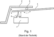
- Fig. 1 shows a highly schematic representation of a partial section through a disc spring clutch according to the prior art. It can be seen firstly a pressure plate 1 shown only in regions, a coupling housing 2, a by means of a plurality of hinge points 3 on the clutch housing 2 movably mounted plate spring 4 and one of a plurality of pressure cams. 6
- the pressure plate 1 is formed with the integrally formed thereon pressure cam 6 as a relatively complex (cast) component, which must also be machined circumferentially before installation in the coupling. Since the pressure plate 1 is heated to some extent during operation of the clutch, the heat on the integrally molded pressure cam 6 can communicate directly to the plate spring 4, which can lead to undesirable structural changes and / or setting operations in the diaphragm spring 4.
- Fig. 2 shows in one Fig. 1 corresponding, again highly schematic representation of an embodiment of a diaphragm spring clutch according to the present invention.
- pressure plate 1 coupling housing 2 and the hinge points 3 for the articulated connection of the plate spring 4 with the coupling housing 2.
- the pressure cams 6 are formed as separate components.
- the pressure cams 6 in corresponding holes of the plate spring 4, which in the region of a circular line 5 (see. Fig. 4 ) are arranged in the radially outer region of the plate spring 4, riveted to the plate spring 4 at 7.
- FIG. 3 is one of the pressure cam 6 of the clutch according to Fig. 2 shown separately again.
- Fig. 4 the diaphragm spring 4 of the clutch according to Fig. 2 (partial) in top view. It will be in Fig. 4 Also, the design of the plate spring 4 with a continuous annular outer area at 4, 6, 7 and 8 with spring tongues visible, with the spring tongues of the clutch-release button (not shown) engages. In the annular outer region of the plate spring 4 while the pressure cams 6 are riveted at regular intervals.
- the solution according to the invention can also be used without problems in existing or otherwise conventional couplings.
- an almost unlimited variability of the coupling characteristic in the sense of a modular system is achieved by the plate spring and pressure plate only by selecting different high or differently shaped pressure cams, and possibly by changing the diameter of the circular line 5, on which the rivets 7 of Pressure cam 6 are with the diaphragm spring 4, couplings with correspondingly different characteristics (spring hardness, operating force curve, torque transmission, etc.) are obtained.
- the cranked version of the pressure cam 6 according to Fig. 5 to 7 also allows almost any adjustment of both the effective height of the pressure cams 6 and the effective effective diameter, ie the diameter of the contact points or lines 9 between pressure cams 6 and pressure plate 1, without the need for significant changes to the other components of the coupling are required.
- the cranked design of the pressure cams 6 also allows an optimization of the space utilization within the clutch, so that the coupling with the same performance in the axial and / or radial direction can optionally be made correspondingly smaller, for example by the Kröpfungs Schemee the pressure cams 6 as space for Housing other components of the coupling can be used.
- a disc spring clutch is obtained with the invention, which can be expected compared to the prior art reduced manufacturing costs with increased variability and modularity.
- the service life or non-stop operating life of the clutch can be significantly increased.
Landscapes
- Engineering & Computer Science (AREA)
- General Engineering & Computer Science (AREA)
- Mechanical Engineering (AREA)
- Mechanical Operated Clutches (AREA)
Description
- Die Erfindung betrifft eine Tellerfederkupplung für ein Kraftfahrzeug gemäß dem Oberbegriff des Patentanspruchs 1.
- Tellerfederkupplungen sind im Automotive-Bereich gebräuchlich zur steuerbaren bzw. trennbaren Kraftübertragung zwischen Verbrennungsmotor und Getriebe. Bekannte Tellerfederkupplungen umfassen typischerweise ein mit der Schwungscheibe des Motors verbundenes, also mit dem Motor rotierendes Kupplungsgehäuse, eine gelenkig mit dem Kupplungsgehäuse verbundene Tellerfeder sowie eine Anpressplatte, welche sich mittels der Tellerfeder mit variabler Anpresskraft auf eine mit der Getriebe-Eingangswelle verbundene Kupplungsscheibe mit Reibbelägen pressen lässt. Hierdurch wird die Kupplungsscheibe zwischen Anpressplatte und Schwungscheibe eingeklemmt und stellt somit eine reibschlüssige, lösbare rotatorische Kopplung zwischen Schwungscheibe und Getriebewelle her.
- Die Kupplungs-Anpressplatte ist üblicherweise ein spanend nachbearbeitetes Gussteil, wobei auf der der Tellerfeder zugewandten Oberfläche der Anpressplatte typischerweise Nocken angeordnet sind, die zur Kraftübertragung zwischen Tellerfeder und Anpressplatte dienen, indem die Tellerfeder zum Einrücken der Kupplung auf die Nocken der Anpressplatte drückt.
- Die Herstellung der mit Nocken versehenen Anpressplatte bei bekannten Tellerfederkupplungen ist jedoch verhältnismäßig aufwändig und damit kostenintensiv, insbesondere was die spanende Bearbeitung der mit den Nocken versehenen und damit geometrisch relativ komplexen Oberfläche der Anpressplatte betrifft. Weiterhin führen die einstückig mit der Anpressplatte ausgeführten Nocken zu einer nicht unerheblichen Wärmeübertragung auf die Tellerfeder, welche jedoch unerwünscht ist, da sich durch zu hohe Temperaturen Gefügeänderungen oder Setzverluste bei der Tellerfeder ergeben können.
- Zur Veränderung der Kupplungscharakteristik solcher bekannter Tellerfederkupplungen ist es zudem häufig erforderlich, die radiale Position der Nocken auf der Anpressplatte und/oder die Form bzw. Höhe der Nocken in Axialrichtung der Kupplung zu verändern. Auch hiermit sind oftmals verhältnismäßig aufwändige Änderungen in Konstruktion und Fertigung, bis hin zur Änderung des der Anpressplatte zugrunde liegenden Gussteils, verbunden.
- Eine Tellerfederkupplung gemäß dem Oberbegriff des Patentanspruchs 1 ist aus der
GB 2 269 866 A - Es ist Aufgabe der vorliegenden Erfindung, eine Tellerfederkupplung zur Verfügung zu stellen, die im Vergleich zum Stand der Technik preiswerter bzw. einfacher zu realisieren ist, bei der die Wärmeübertragung auf die Tellerfeder und damit beispielsweise verbundene Setzverluste der Tellerfeder reduziert werden können, und deren Charakteristik mit geringerem Aufwand geändert werden kann.
- Diese Aufgabe wird erfindungsgemäß gelöst durch eine Tellerfederkupplung gemäß Patentanspruch 1. Bevorzugte Ausführungsbeispiele der Erfindung sind in den abhängigen Patentansprüchen dargelegt.
- Die Tellerfederkupplung umfasst in zunächst bekannter Weise eine Anpressplatte, ein Kupplungsgehäuse sowie eine gelenkig mit dem Kupplungsgehäuse verbundene Tellerfeder. Dabei ist in für sich genommen ebenfalls bekannter Weise zwischen Tellerfeder und Anpressplatte entlang einer Umfangslinie der Tellerfeder verteilt eine Mehrzahl von Drucknocken zur Kraftübertragung von der Umfangslinie der Tellerfeder auf die Anpressplatte angeordnet.
- Die Anordnung der Drucknocken an der Tellerfeder ist vorteilhaft zunächst einmal in Bezug auf die damit ermöglichte einfachere Geometrie, Gestaltung und Herstellung der Anpressplatte und im Hinblick auf die damit verbundene Kostenersparnis bei der Urformung insbesondere durch Gießen, sowie bei der beispielsweise spanenden Bearbeitung der Anpressplatte, da die Anpressplatte erfindungsgemäß keine Drucknocken mehr benötigt, und somit schneller, einfacher und kostengünstiger hergestellt werden kann.
- Ferner ergibt sich durch die mit der Anordnung der Drucknocken an der Tellerfeder verbundene geänderte Geometrie der Drucknocken sowie durch die größere Entfernung der Kontaktflächen zwischen Tellerfeder bzw. Drucknocken und Anpressplatte eine entscheidend reduzierte Wärmeübertragung von der Anpressplatte auf die Tellerfeder. Hierdurch werden Temperaturbelastungen der Tellerfeder und damit verbundene Setzverluste maßgeblich verringert, was die Gebrauchsdauer der Kupplung erhöht und den Bedarf zur Nachstellung der Kupplung im Verlauf deren Lebensdauer verringert. Ebenso kann für die Drucknocken ein besonders abriebfestes Material gewählt werden, was ebenfalls der wartungsfreien Gebrauchsdauer der Kupplung entgegenkommt.
- Die Drucknocken sind als jeweils eigenständige Bauteile ausgebildet, welche mit der Tellerfeder verbunden sind.
- Auf diese Weise ergibt sich eine hohe Variabilität bzw. Modularität für die Tellerfederkupplung, bis hin zur vereinfachten Ausbildung eines Kupplung-Baukastensystems, da die Drucknocken mit unterschiedlichen Maßen und/oder Geometrien ausgebildet und jeweils beispielsweise mit ein und derselben Tellerfeder und Anpressplatte kombiniert werden können, wodurch sich mit geringem Änderungsaufwand Kupplungen mit unterschiedlichen Charakteristiken darstellen lassen. Beispielsweise kann die Höhe der Drucknocken und der wirksame Druckpunkt-Durchmesser der Kupplung durch lediglich Änderung der Maße/Geometrieen der Drucknocken geändert werden, wodurch sich entsprechende Änderungen in der Charakteristik (z.B. Betätigungskräfte, Drehmomentübertragung) der Kupplung ergeben.
- Auch können die Drucknocken auf diese Weise (unabhängig von den Materialien von Tellerfeder und Anpressplatte) in einem besonders geeigneten, beispielsweise abriebfesten und/oder gering wärmeleitenden Material ausgeführt werden, was wiederum der Betriebssicherheit und Lebensdauer der Tellerfederkupplung entgegenkommt. Schließlich kann die Tellerfederkupplung dank dieser Ausführungsform als alternative Bauform bestehender Kupplungen eingeführt werden, indem lediglich Anpressplatte, Drucknocken und Tellerfeder durch die erfindungsgemäße Ausführung ersetzt werden, wohingegen die übrigen Kupplungsbauteile weitestgehend unverändert beibehalten werden können.
- Erfindungsgemäß sind die als eigenständige Bauteile ausgebildeten Drucknocken mit der Tellerfeder vernietet. Hierdurch ergibt sich eine kostengünstige Herstellung der Einheit aus Tellerfeder und mit der Tellerfeder verbundenen Drucknocken, und eine Wärmebelastung der Tellerfeder während der Verbindung mit den Drucknocken wird vermieden.
- Gemäß einer weiteren, bevorzugten Ausführungsform der Erfindung sind die Drucknocken versetzt oder gekröpft ausgebildet. Auf diese Weise wird die Variabilität der Kupplungscharakteristik bzw. Kupplungskennlinien noch weiter vergrößert, indem dank dieser Ausführungsform die Kupplungsgeometrie, die effektive Tellerfeder-Elastizität sowie die effektiven Kraft-Hebellängen zwischen Tellerfeder und Anpressplatte sehr einfach dadurch geändert werden können, dass lediglich die Geometrie der Drucknocken und/oder der Durchmesser der Umfangslinie der Drucknocken-Befestigung an der Tellerfeder verändert werden. Auch kann dank dieser Ausführungsform der Befestigungspunkt der Drucknocken an der Tellerfeder auf einem anderen Radius als der Druckpunkt zwischen den Drucknocken und der Anpressplatte angeordnet werden. Auf diese Weise lassen sich insbesondere auch Bauraumoptimierungen erzielen, wodurch die Kupplung in axialer und/oder radialer Richtung entsprechend kleiner gebaut werden kann.
- Eine weitere bevorzugte Ausführungsform der Erfindung sieht vor, dass die Verbindung zwischen den Drucknocken der Tellerfeder im Bereich von (im Wesentlichen radial verlaufenden) Zungen der Tellerfeder angeordnet ist. Auch diese Ausführungsform ist insbesondere vorteilhaft im Hinblick auf Bauraumoptimierung sowie im Hinblick auf die weitere Anpassung bzw. Veränderung der Tellerfeder-Kennlinie oder -Härte dadurch, dass die Form und oder der Verbindungsort der Drucknocken mit der Tellerfeder in noch weiterem Umfang verändert und somit an die geforderte Kupplungscharakteristik angepasst werden kann.
- Im Folgenden wird die Erfindung anhand lediglich Ausführungsbeispiele darstellender Zeichnungen näher erläutert. Dabei zeigt:
-
Fig. 1 in schematischer Schnittdarstellung zunächst eine Tellerfederkupplung gemäß dem Stand der Technik; -
Fig. 2 in einerFig. 1 entsprechenden Darstellung eine Tellerfederkupplung gemäß einer Ausführungsform der Erfindung mit separaten Drucknocken 6; -
Fig. 3 einen Drucknocken 6 der Tellerfederkupplung gemäßFig. 2 ; -
Fig. 4 in schematischer Draufsicht die Tellerfeder 4 der Kupplung gemäßFig. 2 ; -
Fig. 5 in einerFig. 2 entsprechenden Darstellung eine Tellerfederkupplung gemäß einer weiteren Ausführungsform mit gekröpften Drucknocken 6; -
Fig. 6 einen Drucknocken 6 der Tellerfederkupplung gemäßFig. 5 ; und -
Fig. 7 in einerFig. 4 entsprechenden Darstellung die Tellerfeder 4 der Kupplung gemäßFig. 5 . -
Fig. 1 zeigt in höchst schematischer Darstellung einen Teilschnitt durch eine Tellerfederkupplung gemäß dem Stand der Technik. Man erkennt zunächst eine nur bereichsweise dargestellte Anpressplatte 1, ein Kupplungsgehäuse 2, eine mittels einer Mehrzahl von Gelenkpunkten 3 am Kupplungsgehäuse 2 beweglich befestigte Tellerfeder 4 sowie einen aus einer Mehrzahl an Drucknocken 6. - Durch elastisches Verkippen der Tellerfeder 4 um die (entlang einer Kreislinie auf der Innenseite des Kupplungsgehäuses 2 verteilt angeordneten) Gelenkpunkte 3 mittels Kupplungsbetätigung und Kupplungs-Ausrücker (letztere nicht dargestellt) bewegt sich der äußere (zeichnungsbezogen links gelegene) Umfangsbereich der Tellerfeder entlang der Axialrichtung der Kupplung (zeichnungsbezogen nach oben/unten) auf bzw. ab. Über die wieder entlang einer Kreislinie 5 (vgl.
Fig. 4 ) auf der tellerfederseitigen Oberfläche der Anpressplatte 1 verteilt angeordneten Drucknocken 6 teilt sich die Betätigungsbewegung der Tellerfeder 4 der Anpressplatte 1 mit und presst diese entweder auf die mit der Getriebeeingangswelle verbundene Kupplungsscheibe (beides nicht dargestellt), oder ermöglicht Anpressplatte 1 und Kupplungsscheibe das Abheben von der (hier ebenfalls nicht dargestellten) Schwungscheibe des Verbrennungsmotors. - Man erkennt, dass die Anpressplatte 1 mit den daran einstückig angeformten Drucknocken 6 als verhältnismäßig komplexes (Guss-)Bauteil ausgebildet ist, welches vor dem Einbau in die Kupplung zudem umfänglich spanend bearbeitet werden muss. Da sich die Anpressplatte 1 im Betrieb der Kupplung teilweise stark erwärmt, kann sich die Wärme über die einstückig angeformten Drucknocken 6 direkt auch der Tellerfeder 4 mitteilen, was bei der Tellerfeder 4 zu unerwünschten Gefügeveränderungen und/oder Setzvorgängen führen kann.
- Auch ist eine Veränderung der Geometrie bzw. Charakteristik der Tellerfederkupplung, die üblicherweise insbesondere durch Veränderung der radialen Position bzw. der Höhe der Drucknocken 6 erfolgt, beim Stand der Technik gemäß
Fig. 1 vergleichsweise aufwändig, und kann sogar Veränderungen an dem der Anpressplatte 1 zugrundeliegenden Gussteil erforderlich machen. -
Fig. 2 zeigt in einerFig. 1 entsprechenden, wieder höchst schematischen Darstellung eine Ausführungsform einer Tellerfederkupplung gemäß der vorliegenden Erfindung. - Man erkennt wieder Anpressplatte 1, Kupplungsgehäuse 2 und die Gelenkpunkte 3 für die gelenkige Verbindung der Tellerfeder 4 mit dem Kupplungsgehäuse 2. Im Unterschied zum Stand der Technik gemäß
Fig. 1 sind bei der Ausführungsform gemäßFig. 2 die Drucknocken 6 als separate Bauteile ausgebildet. Dabei sind die Drucknocken 6 in entsprechenden Bohrungen der Tellerfeder 4, die im Bereich einer Kreislinie 5 (vgl.Fig. 4 ) im radial äußeren Bereich der Tellerfeder 4 angeordnet sind, mit der Tellerfeder 4 bei 7 vernietet. - In
Fig. 3 ist einer der Drucknocken 6 der Kupplung gemäßFig. 2 nochmals separat dargestellt. Zudem zeigtFig. 4 die Tellerfeder 4 der Kupplung gemäßFig. 2 (ausschnittsweise) in Draufsicht. Dabei wird inFig. 4 auch die Gestaltung der Tellerfeder 4 mit einem durchgehenden ringförmigen Außenbereich bei 4, 6, 7 sowie mit Federzungen 8 ersichtlich, wobei an den Federzungen der Kupplungs-Ausrücker (nicht dargestellt) angreift. In dem ringförmigen Außenbereich der Tellerfeder 4 sind dabei in regelmäßigen Abständen die Drucknocken 6 eingenietet. - Man erkennt, dass die Ausführung der Drucknocken 6 als eigenständige Bauteile, die mit der Tellerfeder 4 z.B. mittels Vernietung 7 verbunden werden, dazu führt, dass die Anpressplatte 1 geometrisch stark vereinfacht ausgeführt werden kann, nämlich in Form einer einfachen Platte mit im Wesentlichen beidseitig durchgehend flachen Oberflächen. Dies ermöglicht eine entsprechend wesentlich vereinfachte Herstellung und Fertigbearbeitung der Anpressplatte 1 und damit verbundene, entsprechende Kosteneinsparungen.
- Da außer der Einführung der separaten Drucknocken 6 und der vereinfachten Ausführung der Anpressplatte 1 keine weiteren, nennenswerten Änderungen an der Kupplung erforderlich sind, lässt sich die erfindungsgemäße Lösung problemlos auch in bestehende bzw. in ansonsten konventionelle Kupplungen einsetzen. Gleichzeitig wird damit eine fast unbegrenzte Variabilität der Kupplungscharakteristik im Sinne eines Baukastensystems erzielt, indem bei unveränderter Tellerfeder sowie Anpressplatte nur durch Auswahl unterschiedlich hoher bzw. unterschiedlich geformter Drucknocken, und ggf. durch Veränderung des Durchmessers der Kreislinie 5, auf der sich die Vernietungen 7 der Drucknocken 6 mit der Tellerfeder 4 befinden, Kupplungen mit entsprechend unterschiedlicher Charakteristik (Federhärte, Betätigungskraftverlauf, Drehmomentübertragung usw.) erhalten werden.
- Dadurch, dass die Berührungspunkte bzw. linien zwischen Tellerfeder 4 und Anpressplatte 1 (dank der Zuordnung der Drucknocken 6 nicht mehr zur Anpressplatte 1, sondern zur Tellerfeder 4) nun nicht mehr an der Tellerfeder 4, sondern bei 9 an der Anpressplatte 1 liegen, wird zudem die Wärmeübertragung von der ggf. heißen Anpressplatte 1 der Kupplung über die Drucknocken 6 auf die Tellerfeder 4 entscheidend verringert. Dies kommt der Betriebssicherheit und Lebensdauer der Tellerfederkupplung vorteilhaft entgegen, da wärmebedingte Gefügeänderungen und damit verbundene etwaige Setzbewegungen der Tellerfeder auf diese Weise faktisch ausgeschlossen sind. Zusätzlich können auch die Drucknocken 6 selbst in einem vergleichsweise gering wärmeleitenden und/oder abriebfesten Werkstoff ausgeführt werden, wodurch sich die Wärmeübertragung auf die Tellerfeder 4 bzw. der Kupplungsverschleiß weiter verringern lässt.
- Die gekröpfte Ausführung des Drucknockens 6 gemäß
Fig. 5 bis 7 erlaubt zudem eine nahezu beliebige Anpassung sowohl der effektiven Höhe der Drucknocken 6 als auch des effektiven Wirkdurchmessers, also des Durchmessers der Berührungspunkte bzw. linien 9 zwischen Drucknocken 6 und Anpressplatte 1, ohne dass hierzu nennenswerte Änderungen an den sonstigen Bauteilen der Kupplung erforderlich sind. - Auch lässt sich auf diese Weise, insbesondere durch Auswahl des Kröpfungsmaßes und entsprechenden Durchmessers der Kreislinie 5, auf der die Drucknocken 6 mit der Tellerfeder 4 vernietet werden, die Kennlinie bzw. Kupplungshärte anpassen, ohne dass sonstige Änderungen an der Kupplung erforderlich sind. Nicht zuletzt erlaubt die gekröpfte Ausführung der Drucknocken 6 auch eine Optimierung der Bauraumausnutzung innerhalb der Kupplung, so dass die Kupplung bei gleicher Leistungsfähigkeit in axialer und/oder radialer Richtung ggf. entsprechend kleiner ausgeführt werden kann, beispielsweise indem die Kröpfungsbereiche der Drucknocken 6 als Bauraum zur Unterbringung anderer Bauteile der Kupplung genutzt werden.
- Im Ergebnis wird mit der Erfindung eine Tellerfederkupplung erhalten, die im Vergleich zum Stand der Technik reduzierte Herstellungskosten bei gleichzeitig erhöhter Variabilität und Modularität erwarten lässt. Zudem lässt sich aufgrund der Optimierung der Reibpaarung sowie aufgrund Minimierung der Wärmeübertragung zwischen Tellerfeder und Anpressplatte die Lebensdauer bzw. nachstellfreie Betriebsdauer der Kupplung maßgeblich erhöhen.
-
- 1
- Anpressplatte
- 2
- Kupplungsgehäuse
- 3
- Tellerfeder-Aufhängung, Gelenkpunkt
- 4
- Tellerfeder
- 5
- Kreislinie, Befestigungsdurchmesser
- 6
- Drucknocken
- 7
- Vernietung
- 8
- Tellerfeder-Zungen
- 9
- Berührungspunkt, Berührungslinie
Claims (3)
- Tellerfederkupplung für ein Kraftfahrzeug, die Kupplung umfassend eine Anpressplatte (1), ein Kupplungsgehäuse (2) sowie eine gelenkig (3) mit dem Kupplungsgehäuse (2) verbundene Tellerfeder (4), wobei zwischen Tellerfeder (4) und Anpressplatte (1) entlang einer Umfangslinie (5) der Tellerfeder (4) verteilt eine Mehrzahl von Drucknocken (6) zur Kraftübertragung von der Umfangslinie (5) der Tellerfeder (4) auf die Anpressplatte (1) angeordnet sind, wobei die Drucknocken (6) an der Tellerfeder (4) angeordnet und als jeweils eigenständiges Bauteil ausgebildet sind, dadurch gekennzeichnet, dass die Drucknocken (6) mit der Tellerfeder (4) vernietet sind.
- Tellerfederkupplung nach Anspruch 1, dadurch gekennzeichnet, dass dass die Drucknocken (6) versetzt oder gekröpft ausgebildet sind.
- Tellerfederkupplung nach Anspruch 1 oder 2, dadurch gekennzeichnet, dass die Vernietung (7) zwischen den Drucknocken (6) und der Tellerfeder (4) im Bereich von Zungen (8) der Tellerfeder (4) angeordnet ist.
Applications Claiming Priority (1)
| Application Number | Priority Date | Filing Date | Title |
|---|---|---|---|
| DE102014201401 | 2014-01-27 |
Publications (3)
| Publication Number | Publication Date |
|---|---|
| EP2899419A2 EP2899419A2 (de) | 2015-07-29 |
| EP2899419A3 EP2899419A3 (de) | 2016-01-20 |
| EP2899419B1 true EP2899419B1 (de) | 2017-03-15 |
Family
ID=52282445
Family Applications (1)
| Application Number | Title | Priority Date | Filing Date |
|---|---|---|---|
| EP14199087.9A Not-in-force EP2899419B1 (de) | 2014-01-27 | 2014-12-19 | Tellerfederkupplung |
Country Status (2)
| Country | Link |
|---|---|
| EP (1) | EP2899419B1 (de) |
| DE (1) | DE102014226520A1 (de) |
Families Citing this family (1)
| Publication number | Priority date | Publication date | Assignee | Title |
|---|---|---|---|---|
| DE102020001569A1 (de) | 2020-03-10 | 2021-09-16 | Diehl Metall Stiftung & Co. Kg | Tellerfederkupplung |
Family Cites Families (5)
| Publication number | Priority date | Publication date | Assignee | Title |
|---|---|---|---|---|
| FR2693244B1 (fr) * | 1992-07-01 | 1994-08-05 | Valeo | Embrayage a friction pour vehicule automobile et diaphragme elastique pour un tel embrayage. |
| FR2694967B1 (fr) * | 1992-08-21 | 1994-10-07 | Valeo | Dispositif d'embrayage à friction notamment pour véhicule automobile et diaphragme élastique pour un tel dispositif d'embrayage. |
| DE19716396B4 (de) * | 1997-04-18 | 2006-02-23 | Bayerische Motoren Werke Ag | Einscheibenkupplung für Schaltgetriebe |
| DE102007053724A1 (de) * | 2006-12-16 | 2008-06-19 | Zf Friedrichshafen Ag | Kupplungsvorrichtung |
| DE102013200496A1 (de) * | 2012-01-30 | 2013-08-01 | Schaeffler Technologies AG & Co. KG | Reibungskupplungseinrichtung |
-
2014
- 2014-12-19 DE DE102014226520.7A patent/DE102014226520A1/de not_active Withdrawn
- 2014-12-19 EP EP14199087.9A patent/EP2899419B1/de not_active Not-in-force
Non-Patent Citations (1)
| Title |
|---|
| None * |
Also Published As
| Publication number | Publication date |
|---|---|
| EP2899419A3 (de) | 2016-01-20 |
| DE102014226520A1 (de) | 2015-07-30 |
| EP2899419A2 (de) | 2015-07-29 |
Similar Documents
| Publication | Publication Date | Title |
|---|---|---|
| EP3123046B1 (de) | Kupplung in blechbauweise mit wenigstens zwei kupplungsscheiben | |
| EP3069035B1 (de) | Reibungskupplung | |
| EP1832769A2 (de) | Reibungskupplung | |
| DE102015205832A1 (de) | Axiale Lamellenkupplung | |
| DE19743782B4 (de) | Kupplungsanordnung | |
| EP3137781B1 (de) | Deckelanordnung für eine reibungskupplung | |
| EP3133308B1 (de) | Axiale lamellenkupplung | |
| EP3728889B1 (de) | Drehmomentübertragungseinheit und antriebsstrang | |
| EP3332140B1 (de) | Reibungskupplungseinrichtung | |
| EP2899419A2 (de) | Tellerfederkupplung | |
| EP2807389B1 (de) | Kupplungsvorrichtung | |
| EP2824346B1 (de) | Reibungskupplung für Antriebsstrang eines Kraftfahrzeuges | |
| WO2013139634A1 (de) | Nachstelleinrichtung für eine reibkupplung | |
| DE102017130853B4 (de) | Kupplungseinrichtung | |
| EP3085979A1 (de) | Tellerfeder mit integrierten stützfederabschnitten | |
| EP3155277B1 (de) | Kupplungsvorrichtung | |
| EP2890911B1 (de) | Reibungskupplungseinrichtung | |
| EP3874174B1 (de) | Reibungskupplung | |
| DE112017000805B4 (de) | Kupplungssystem mit deckelfester Betätigungsvorrichtung sowie in der Kupplung liegendem Stützlager in Form eines Deckellagers | |
| EP2957789A2 (de) | Stützfeder für ein betätigungssystem einer reibkupplung | |
| DE102015216072A1 (de) | Kupplungsvorrichtung | |
| DE102016202300A1 (de) | Deckelanordnung für eine Reibungskupplung | |
| DE102013200619A1 (de) | Selbstnachstellende Reibungskupplung | |
| DE102013221836A1 (de) | Deckelanordnung für eine Reibungskupplung sowie Verfahren zum Betätigen einer Reibungskupplung | |
| DE102013218723A1 (de) | Deckelanordnung für eine Reibungskupplung |
Legal Events
| Date | Code | Title | Description |
|---|---|---|---|
| PUAI | Public reference made under article 153(3) epc to a published international application that has entered the european phase |
Free format text: ORIGINAL CODE: 0009012 |
|
| 17P | Request for examination filed |
Effective date: 20141219 |
|
| AK | Designated contracting states |
Kind code of ref document: A2 Designated state(s): AL AT BE BG CH CY CZ DE DK EE ES FI FR GB GR HR HU IE IS IT LI LT LU LV MC MK MT NL NO PL PT RO RS SE SI SK SM TR |
|
| AX | Request for extension of the european patent |
Extension state: BA ME |
|
| PUAL | Search report despatched |
Free format text: ORIGINAL CODE: 0009013 |
|
| AK | Designated contracting states |
Kind code of ref document: A3 Designated state(s): AL AT BE BG CH CY CZ DE DK EE ES FI FR GB GR HR HU IE IS IT LI LT LU LV MC MK MT NL NO PL PT RO RS SE SI SK SM TR |
|
| AX | Request for extension of the european patent |
Extension state: BA ME |
|
| RIC1 | Information provided on ipc code assigned before grant |
Ipc: F16D 13/58 20060101AFI20151215BHEP |
|
| 17P | Request for examination filed |
Effective date: 20160720 |
|
| RBV | Designated contracting states (corrected) |
Designated state(s): AL AT BE BG CH CY CZ DE DK EE ES FI FR GB GR HR HU IE IS IT LI LT LU LV MC MK MT NL NO PL PT RO RS SE SI SK SM TR |
|
| GRAP | Despatch of communication of intention to grant a patent |
Free format text: ORIGINAL CODE: EPIDOSNIGR1 |
|
| INTG | Intention to grant announced |
Effective date: 20161115 |
|
| GRAS | Grant fee paid |
Free format text: ORIGINAL CODE: EPIDOSNIGR3 |
|
| GRAA | (expected) grant |
Free format text: ORIGINAL CODE: 0009210 |
|
| AK | Designated contracting states |
Kind code of ref document: B1 Designated state(s): AL AT BE BG CH CY CZ DE DK EE ES FI FR GB GR HR HU IE IS IT LI LT LU LV MC MK MT NL NO PL PT RO RS SE SI SK SM TR |
|
| REG | Reference to a national code |
Ref country code: CH Ref legal event code: EP Ref country code: GB Ref legal event code: FG4D Free format text: NOT ENGLISH |
|
| REG | Reference to a national code |
Ref country code: IE Ref legal event code: FG4D Free format text: LANGUAGE OF EP DOCUMENT: GERMAN |
|
| REG | Reference to a national code |
Ref country code: AT Ref legal event code: REF Ref document number: 875905 Country of ref document: AT Kind code of ref document: T Effective date: 20170415 |
|
| REG | Reference to a national code |
Ref country code: DE Ref legal event code: R096 Ref document number: 502014003002 Country of ref document: DE |
|
| REG | Reference to a national code |
Ref country code: NL Ref legal event code: MP Effective date: 20170315 |
|
| REG | Reference to a national code |
Ref country code: LT Ref legal event code: MG4D |
|
| PG25 | Lapsed in a contracting state [announced via postgrant information from national office to epo] |
Ref country code: HR Free format text: LAPSE BECAUSE OF FAILURE TO SUBMIT A TRANSLATION OF THE DESCRIPTION OR TO PAY THE FEE WITHIN THE PRESCRIBED TIME-LIMIT Effective date: 20170315 Ref country code: NO Free format text: LAPSE BECAUSE OF FAILURE TO SUBMIT A TRANSLATION OF THE DESCRIPTION OR TO PAY THE FEE WITHIN THE PRESCRIBED TIME-LIMIT Effective date: 20170615 Ref country code: LT Free format text: LAPSE BECAUSE OF FAILURE TO SUBMIT A TRANSLATION OF THE DESCRIPTION OR TO PAY THE FEE WITHIN THE PRESCRIBED TIME-LIMIT Effective date: 20170315 Ref country code: FI Free format text: LAPSE BECAUSE OF FAILURE TO SUBMIT A TRANSLATION OF THE DESCRIPTION OR TO PAY THE FEE WITHIN THE PRESCRIBED TIME-LIMIT Effective date: 20170315 Ref country code: GR Free format text: LAPSE BECAUSE OF FAILURE TO SUBMIT A TRANSLATION OF THE DESCRIPTION OR TO PAY THE FEE WITHIN THE PRESCRIBED TIME-LIMIT Effective date: 20170616 |
|
| PG25 | Lapsed in a contracting state [announced via postgrant information from national office to epo] |
Ref country code: LV Free format text: LAPSE BECAUSE OF FAILURE TO SUBMIT A TRANSLATION OF THE DESCRIPTION OR TO PAY THE FEE WITHIN THE PRESCRIBED TIME-LIMIT Effective date: 20170315 Ref country code: RS Free format text: LAPSE BECAUSE OF FAILURE TO SUBMIT A TRANSLATION OF THE DESCRIPTION OR TO PAY THE FEE WITHIN THE PRESCRIBED TIME-LIMIT Effective date: 20170315 Ref country code: BG Free format text: LAPSE BECAUSE OF FAILURE TO SUBMIT A TRANSLATION OF THE DESCRIPTION OR TO PAY THE FEE WITHIN THE PRESCRIBED TIME-LIMIT Effective date: 20170615 Ref country code: SE Free format text: LAPSE BECAUSE OF FAILURE TO SUBMIT A TRANSLATION OF THE DESCRIPTION OR TO PAY THE FEE WITHIN THE PRESCRIBED TIME-LIMIT Effective date: 20170315 |
|
| PG25 | Lapsed in a contracting state [announced via postgrant information from national office to epo] |
Ref country code: NL Free format text: LAPSE BECAUSE OF FAILURE TO SUBMIT A TRANSLATION OF THE DESCRIPTION OR TO PAY THE FEE WITHIN THE PRESCRIBED TIME-LIMIT Effective date: 20170315 |
|
| PG25 | Lapsed in a contracting state [announced via postgrant information from national office to epo] |
Ref country code: RO Free format text: LAPSE BECAUSE OF FAILURE TO SUBMIT A TRANSLATION OF THE DESCRIPTION OR TO PAY THE FEE WITHIN THE PRESCRIBED TIME-LIMIT Effective date: 20170315 Ref country code: CZ Free format text: LAPSE BECAUSE OF FAILURE TO SUBMIT A TRANSLATION OF THE DESCRIPTION OR TO PAY THE FEE WITHIN THE PRESCRIBED TIME-LIMIT Effective date: 20170315 Ref country code: ES Free format text: LAPSE BECAUSE OF FAILURE TO SUBMIT A TRANSLATION OF THE DESCRIPTION OR TO PAY THE FEE WITHIN THE PRESCRIBED TIME-LIMIT Effective date: 20170315 Ref country code: IT Free format text: LAPSE BECAUSE OF FAILURE TO SUBMIT A TRANSLATION OF THE DESCRIPTION OR TO PAY THE FEE WITHIN THE PRESCRIBED TIME-LIMIT Effective date: 20170315 Ref country code: EE Free format text: LAPSE BECAUSE OF FAILURE TO SUBMIT A TRANSLATION OF THE DESCRIPTION OR TO PAY THE FEE WITHIN THE PRESCRIBED TIME-LIMIT Effective date: 20170315 Ref country code: SK Free format text: LAPSE BECAUSE OF FAILURE TO SUBMIT A TRANSLATION OF THE DESCRIPTION OR TO PAY THE FEE WITHIN THE PRESCRIBED TIME-LIMIT Effective date: 20170315 |
|
| PG25 | Lapsed in a contracting state [announced via postgrant information from national office to epo] |
Ref country code: SM Free format text: LAPSE BECAUSE OF FAILURE TO SUBMIT A TRANSLATION OF THE DESCRIPTION OR TO PAY THE FEE WITHIN THE PRESCRIBED TIME-LIMIT Effective date: 20170315 Ref country code: PT Free format text: LAPSE BECAUSE OF FAILURE TO SUBMIT A TRANSLATION OF THE DESCRIPTION OR TO PAY THE FEE WITHIN THE PRESCRIBED TIME-LIMIT Effective date: 20170717 Ref country code: IS Free format text: LAPSE BECAUSE OF FAILURE TO SUBMIT A TRANSLATION OF THE DESCRIPTION OR TO PAY THE FEE WITHIN THE PRESCRIBED TIME-LIMIT Effective date: 20170715 Ref country code: PL Free format text: LAPSE BECAUSE OF FAILURE TO SUBMIT A TRANSLATION OF THE DESCRIPTION OR TO PAY THE FEE WITHIN THE PRESCRIBED TIME-LIMIT Effective date: 20170315 |
|
| REG | Reference to a national code |
Ref country code: DE Ref legal event code: R097 Ref document number: 502014003002 Country of ref document: DE |
|
| REG | Reference to a national code |
Ref country code: FR Ref legal event code: PLFP Year of fee payment: 4 |
|
| PLBE | No opposition filed within time limit |
Free format text: ORIGINAL CODE: 0009261 |
|
| STAA | Information on the status of an ep patent application or granted ep patent |
Free format text: STATUS: NO OPPOSITION FILED WITHIN TIME LIMIT |
|
| PG25 | Lapsed in a contracting state [announced via postgrant information from national office to epo] |
Ref country code: DK Free format text: LAPSE BECAUSE OF FAILURE TO SUBMIT A TRANSLATION OF THE DESCRIPTION OR TO PAY THE FEE WITHIN THE PRESCRIBED TIME-LIMIT Effective date: 20170315 |
|
| 26N | No opposition filed |
Effective date: 20171218 |
|
| PG25 | Lapsed in a contracting state [announced via postgrant information from national office to epo] |
Ref country code: SI Free format text: LAPSE BECAUSE OF FAILURE TO SUBMIT A TRANSLATION OF THE DESCRIPTION OR TO PAY THE FEE WITHIN THE PRESCRIBED TIME-LIMIT Effective date: 20170315 |
|
| REG | Reference to a national code |
Ref country code: CH Ref legal event code: PL |
|
| REG | Reference to a national code |
Ref country code: IE Ref legal event code: MM4A |
|
| PG25 | Lapsed in a contracting state [announced via postgrant information from national office to epo] |
Ref country code: MT Free format text: LAPSE BECAUSE OF FAILURE TO SUBMIT A TRANSLATION OF THE DESCRIPTION OR TO PAY THE FEE WITHIN THE PRESCRIBED TIME-LIMIT Effective date: 20170315 Ref country code: LU Free format text: LAPSE BECAUSE OF NON-PAYMENT OF DUE FEES Effective date: 20171219 |
|
| REG | Reference to a national code |
Ref country code: BE Ref legal event code: MM Effective date: 20171231 |
|
| PG25 | Lapsed in a contracting state [announced via postgrant information from national office to epo] |
Ref country code: IE Free format text: LAPSE BECAUSE OF NON-PAYMENT OF DUE FEES Effective date: 20171219 |
|
| PG25 | Lapsed in a contracting state [announced via postgrant information from national office to epo] |
Ref country code: LI Free format text: LAPSE BECAUSE OF NON-PAYMENT OF DUE FEES Effective date: 20171231 Ref country code: CH Free format text: LAPSE BECAUSE OF NON-PAYMENT OF DUE FEES Effective date: 20171231 Ref country code: BE Free format text: LAPSE BECAUSE OF NON-PAYMENT OF DUE FEES Effective date: 20171231 |
|
| PG25 | Lapsed in a contracting state [announced via postgrant information from national office to epo] |
Ref country code: HU Free format text: LAPSE BECAUSE OF FAILURE TO SUBMIT A TRANSLATION OF THE DESCRIPTION OR TO PAY THE FEE WITHIN THE PRESCRIBED TIME-LIMIT; INVALID AB INITIO Effective date: 20141219 Ref country code: MC Free format text: LAPSE BECAUSE OF FAILURE TO SUBMIT A TRANSLATION OF THE DESCRIPTION OR TO PAY THE FEE WITHIN THE PRESCRIBED TIME-LIMIT Effective date: 20170315 |
|
| GBPC | Gb: european patent ceased through non-payment of renewal fee |
Effective date: 20181219 |
|
| PG25 | Lapsed in a contracting state [announced via postgrant information from national office to epo] |
Ref country code: CY Free format text: LAPSE BECAUSE OF FAILURE TO SUBMIT A TRANSLATION OF THE DESCRIPTION OR TO PAY THE FEE WITHIN THE PRESCRIBED TIME-LIMIT Effective date: 20170315 |
|
| PG25 | Lapsed in a contracting state [announced via postgrant information from national office to epo] |
Ref country code: MK Free format text: LAPSE BECAUSE OF FAILURE TO SUBMIT A TRANSLATION OF THE DESCRIPTION OR TO PAY THE FEE WITHIN THE PRESCRIBED TIME-LIMIT Effective date: 20170315 |
|
| PG25 | Lapsed in a contracting state [announced via postgrant information from national office to epo] |
Ref country code: GB Free format text: LAPSE BECAUSE OF NON-PAYMENT OF DUE FEES Effective date: 20181219 |
|
| PG25 | Lapsed in a contracting state [announced via postgrant information from national office to epo] |
Ref country code: TR Free format text: LAPSE BECAUSE OF FAILURE TO SUBMIT A TRANSLATION OF THE DESCRIPTION OR TO PAY THE FEE WITHIN THE PRESCRIBED TIME-LIMIT Effective date: 20170315 |
|
| PG25 | Lapsed in a contracting state [announced via postgrant information from national office to epo] |
Ref country code: AL Free format text: LAPSE BECAUSE OF FAILURE TO SUBMIT A TRANSLATION OF THE DESCRIPTION OR TO PAY THE FEE WITHIN THE PRESCRIBED TIME-LIMIT Effective date: 20170315 |
|
| REG | Reference to a national code |
Ref country code: AT Ref legal event code: MM01 Ref document number: 875905 Country of ref document: AT Kind code of ref document: T Effective date: 20191219 |
|
| PG25 | Lapsed in a contracting state [announced via postgrant information from national office to epo] |
Ref country code: AT Free format text: LAPSE BECAUSE OF NON-PAYMENT OF DUE FEES Effective date: 20191219 |
|
| PGFP | Annual fee paid to national office [announced via postgrant information from national office to epo] |
Ref country code: FR Payment date: 20221222 Year of fee payment: 9 |
|
| PGFP | Annual fee paid to national office [announced via postgrant information from national office to epo] |
Ref country code: DE Payment date: 20230216 Year of fee payment: 9 |
|
| P01 | Opt-out of the competence of the unified patent court (upc) registered |
Effective date: 20230523 |
|
| REG | Reference to a national code |
Ref country code: DE Ref legal event code: R119 Ref document number: 502014003002 Country of ref document: DE |
|
| PG25 | Lapsed in a contracting state [announced via postgrant information from national office to epo] |
Ref country code: DE Free format text: LAPSE BECAUSE OF NON-PAYMENT OF DUE FEES Effective date: 20240702 |
|
| PG25 | Lapsed in a contracting state [announced via postgrant information from national office to epo] |
Ref country code: FR Free format text: LAPSE BECAUSE OF NON-PAYMENT OF DUE FEES Effective date: 20231231 |
|
| PG25 | Lapsed in a contracting state [announced via postgrant information from national office to epo] |
Ref country code: FR Free format text: LAPSE BECAUSE OF NON-PAYMENT OF DUE FEES Effective date: 20231231 Ref country code: DE Free format text: LAPSE BECAUSE OF NON-PAYMENT OF DUE FEES Effective date: 20240702 |