EP2899417A1 - Fluid dynamic bearing device and motor with same - Google Patents
Fluid dynamic bearing device and motor with same Download PDFInfo
- Publication number
- EP2899417A1 EP2899417A1 EP13839464.8A EP13839464A EP2899417A1 EP 2899417 A1 EP2899417 A1 EP 2899417A1 EP 13839464 A EP13839464 A EP 13839464A EP 2899417 A1 EP2899417 A1 EP 2899417A1
- Authority
- EP
- European Patent Office
- Prior art keywords
- bearing
- radial
- gap
- housing
- shaft member
- Prior art date
- Legal status (The legal status is an assumption and is not a legal conclusion. Google has not performed a legal analysis and makes no representation as to the accuracy of the status listed.)
- Granted
Links
Images


Classifications
-
- F—MECHANICAL ENGINEERING; LIGHTING; HEATING; WEAPONS; BLASTING
- F16—ENGINEERING ELEMENTS AND UNITS; GENERAL MEASURES FOR PRODUCING AND MAINTAINING EFFECTIVE FUNCTIONING OF MACHINES OR INSTALLATIONS; THERMAL INSULATION IN GENERAL
- F16C—SHAFTS; FLEXIBLE SHAFTS; ELEMENTS OR CRANKSHAFT MECHANISMS; ROTARY BODIES OTHER THAN GEARING ELEMENTS; BEARINGS
- F16C17/00—Sliding-contact bearings for exclusively rotary movement
- F16C17/10—Sliding-contact bearings for exclusively rotary movement for both radial and axial load
- F16C17/102—Sliding-contact bearings for exclusively rotary movement for both radial and axial load with grooves in the bearing surface to generate hydrodynamic pressure
- F16C17/107—Sliding-contact bearings for exclusively rotary movement for both radial and axial load with grooves in the bearing surface to generate hydrodynamic pressure with at least one surface for radial load and at least one surface for axial load
-
- F—MECHANICAL ENGINEERING; LIGHTING; HEATING; WEAPONS; BLASTING
- F16—ENGINEERING ELEMENTS AND UNITS; GENERAL MEASURES FOR PRODUCING AND MAINTAINING EFFECTIVE FUNCTIONING OF MACHINES OR INSTALLATIONS; THERMAL INSULATION IN GENERAL
- F16C—SHAFTS; FLEXIBLE SHAFTS; ELEMENTS OR CRANKSHAFT MECHANISMS; ROTARY BODIES OTHER THAN GEARING ELEMENTS; BEARINGS
- F16C33/00—Parts of bearings; Special methods for making bearings or parts thereof
- F16C33/02—Parts of sliding-contact bearings
- F16C33/04—Brasses; Bushes; Linings
- F16C33/06—Sliding surface mainly made of metal
- F16C33/10—Construction relative to lubrication
- F16C33/1025—Construction relative to lubrication with liquid, e.g. oil, as lubricant
- F16C33/103—Construction relative to lubrication with liquid, e.g. oil, as lubricant retained in or near the bearing
- F16C33/104—Construction relative to lubrication with liquid, e.g. oil, as lubricant retained in or near the bearing in a porous body, e.g. oil impregnated sintered sleeve
-
- F—MECHANICAL ENGINEERING; LIGHTING; HEATING; WEAPONS; BLASTING
- F16—ENGINEERING ELEMENTS AND UNITS; GENERAL MEASURES FOR PRODUCING AND MAINTAINING EFFECTIVE FUNCTIONING OF MACHINES OR INSTALLATIONS; THERMAL INSULATION IN GENERAL
- F16C—SHAFTS; FLEXIBLE SHAFTS; ELEMENTS OR CRANKSHAFT MECHANISMS; ROTARY BODIES OTHER THAN GEARING ELEMENTS; BEARINGS
- F16C43/00—Assembling bearings
- F16C43/02—Assembling sliding-contact bearings
-
- F—MECHANICAL ENGINEERING; LIGHTING; HEATING; WEAPONS; BLASTING
- F16—ENGINEERING ELEMENTS AND UNITS; GENERAL MEASURES FOR PRODUCING AND MAINTAINING EFFECTIVE FUNCTIONING OF MACHINES OR INSTALLATIONS; THERMAL INSULATION IN GENERAL
- F16C—SHAFTS; FLEXIBLE SHAFTS; ELEMENTS OR CRANKSHAFT MECHANISMS; ROTARY BODIES OTHER THAN GEARING ELEMENTS; BEARINGS
- F16C2240/00—Specified values or numerical ranges of parameters; Relations between them
- F16C2240/40—Linear dimensions, e.g. length, radius, thickness, gap
- F16C2240/46—Gap sizes or clearances
-
- F—MECHANICAL ENGINEERING; LIGHTING; HEATING; WEAPONS; BLASTING
- F16—ENGINEERING ELEMENTS AND UNITS; GENERAL MEASURES FOR PRODUCING AND MAINTAINING EFFECTIVE FUNCTIONING OF MACHINES OR INSTALLATIONS; THERMAL INSULATION IN GENERAL
- F16C—SHAFTS; FLEXIBLE SHAFTS; ELEMENTS OR CRANKSHAFT MECHANISMS; ROTARY BODIES OTHER THAN GEARING ELEMENTS; BEARINGS
- F16C2370/00—Apparatus relating to physics, e.g. instruments
- F16C2370/12—Hard disk drives or the like
Definitions
- a present invention relates to a fluid dynamic bearing device and a motor including the fluid dynamic bearing device.
- fluid dynamic bearing devices have features in their high speed rotation, high rotational accuracy, quietness, and the like.
- the fluid dynamic bearing devices are suitably used as bearing devices for motors to be mounted to various electrical apparatus such as information apparatus, and more specifically, as bearing devices for spindle motors to be built in disk drives of HDDs and the like, for fan motors to be built in PCs and the like, or for polygon scanner motors to be built in laser beam printers (LBPs).
- LBPs laser beam printers
- the fluid dynamic bearing device includes a housing having a bottomed cylindrical shape (cup shape), a bearing sleeve fixed to an inner periphery of the housing, a shaft member removably inserted along an inner periphery of the bearing sleeve, a radial bearing portion for supporting the shaft member in a radial direction by an oil film of lubricating oil formed in a radial bearing gap, a thrust bearing portion for supporting the shaft member in a thrust direction, a bottom gap having the thrust bearing portion received therein, and an annular member (sealing member) fixed to an inner periphery of an opening portion of the housing.
- the annular member is fixed to the inner periphery of the opening portion of the housing in a state of engaging with the bearing sleeve in an axial direction (state of engaging with the bearing sleeve in a direction of removing the bearing sleeve). Accordingly, a force for fixing the bearing sleeve to the housing (force for removing the bearing sleeve) is increased, and thus relative positions of the housing and the bearing sleeve in the axial direction, and also desired bearing performance are maintained stably.
- the fluid dynamic bearing device is used in a so-called fully-filled state in which an entire interior space of the housing is filled with the lubricating oil, and a sealing space (radial gap having a gap width larger than that of the radial bearing gap) is formed between an inner peripheral surface of the annular member and an outer peripheral surface of the shaft member.
- the sealing space is designed to function as a buffer for absorbing an amount of a volume change accompanied with a temperature change of the lubricating oil, thereby being capable of always maintaining an oil level of the lubricating oil in the sealing space within a range of the assumed temperature change. Therefore, reduction in bearing performance and contamination of peripheral environment, which result from leakage of the lubricating oil to an outside, can be prevented as much as possible.
- Patent Literature 1 JP 2003-307212 A
- a fluid dynamic bearing device comprising: a housing formed into a bottomed cylindrical shape so as to have one open axial end and another closed axial end; a bearing sleeve fixed to an inner periphery of the housing; a shaft member removably inserted along an inner periphery of the bearing sleeve; an annular member having an inner peripheral surface for defining a radial gap together with an outer peripheral surface of the shaft member, the annular member being fixed to an inner periphery of the one open axial end of the housing in a state of engaging with the bearing sleeve in an axial direction; a radial bearing portion for supporting the shaft member in a radial direction by an oil film of lubricating oil, which is formed in a radial bearing gap defined between an inner peripheral surface of the bearing sleeve and the outer peripheral surface of the shaft member; a thrust bearing portion for
- the void section is formed in the interior space of the housing (hereinafter simply referred to also as "interior space").
- an amount of the lubricating oil filled into the interior space of the housing is smaller than a volume of the above-mentioned interior space, and that a region filled with no lubricating oil is formed in the above-mentioned interior space.
- the shaft member is insertable into and removable from the bearing sleeve.
- operations to inject oil into the interior space can be carried out after the bearing sleeve and the annular member are fixed to the inner periphery of the housing and before the shaft member is inserted along the inner periphery of the bearing sleeve.
- oil injecting operations can be carried out more easily and appropriately.
- the lubricating oil is liable to leak along with insertion of the shaft member along the inner periphery of the bearing sleeve after oil injection.
- a mechanism of occurrence of leakage of the lubricating oil is described with reference to FIGS. 7A and 7B .
- a bearing sleeve 108 and an annular member 109 are fixed to an inner periphery of a housing 107 so that a bottom gap 105 is defined between a bottom portion of the housing 107 and the bearing sleeve 108. Then, lubricating oil 110 is injected into an interior space of the housing 107.
- a shaft member 102 is inserted into the annular member 109 and along an inner periphery of the bearing sleeve 108.
- the lubricating oil 110 flows by a capillary force toward an opening portion of the housing 107 through a radial gap (radial bearing gap) defined between (an outer peripheral surface of) the shaft member 102 and (an inner peripheral surface of) the bearing sleeve 108 so as to have a minute gap width. Then, the lubricating oil 110 adheres to the outer peripheral surface of the shaft member 102, and also to an inner peripheral surface of the annular member 109. Along with progress of insertion of the shaft member 102, the air present in the interior space of the housing 107 (between the shaft member 102 and the housing 107) is compressed.
- the leakage can be solved in such a manner that, when d 1 represents a gap width of the radial bearing gap and d 2 represents a gap width of the radial gap, the gap width d 2 of the radial gap is set so as to satisfy a relationship of 30d 1 ⁇ d 2 .
- the gap width d 2 of the radial gap is set so as to satisfy a relationship of 30d 1 ⁇ d 2 .
- the gap width d 2 of the radial gap is set to an extremely large size, a contact area between the bearing sleeve and the annular member is extremely small, and hence it may be difficult to ensure a necessary force for removing the bearing sleeve. Therefore, it is preferred that a relationship of d 2 ⁇ 250d 1 be satisfied.
- the bearing device having the above-mentioned configuration may further comprise a communication path for communicating the radial gap and the bottom gap to each other.
- the above-mentioned communication path may comprise: a first path formed between the housing and the bearing sleeve so as to have one end that is open to the bottom gap; and a second path formed between the bearing sleeve and the annular member so as to have one end that is open to the radial gap, and another end that is continuous with another end of the first path.
- the bearing sleeve can be fixed to the inner periphery of the housing by, for example, press fitting (specifically, press fitting with a large interference, the same is true for the following means), bonding, or press-fit bonding (combination of press fitting and bonding).
- press fitting specifically, press fitting with a large interference, the same is true for the following means
- bonding or press-fit bonding (combination of press fitting and bonding).
- press fitting deformation of the bearing sleeve accompanied with press fitting affects an inner peripheral surface of the bearing sleeve, and may exert an adverse influence on width accuracy of the radial bearing gap.
- bonding it is necessary to relatively position the housing and the bearing sleeve and retain the housing and the bearing sleeve until an applied adhesive is cured, and in addition, it is sometimes necessary to provide another process of curing the adhesive.
- the bearing sleeve is fixed to the inner periphery of the housing while being sandwiched from both axial sides thereof between the annular member and the bottom portion of the housing. In this manner, it is possible to reduce time and effort necessary for assembly. In addition, exertion of an adverse influence on bearing performance of the radial bearing portion can be prevented as much as possible.
- the radial bearing gap may be formed at two axial positions.
- radial dynamic pressure generating portions for causing dynamic pressure generating action in the lubricating oil in the radial bearing gaps may be formed also at two axial positions.
- one of the radial dynamic pressure generating portions be formed into such a shape as to pump the lubricating oil, which is filled in one of the radial bearing gaps, into another one of the radial bearing gaps, and that another one of the radial dynamic pressure generating portions be formed into such a shape as to pump the lubricating oil, which is filled in the another one of the radial bearing gaps, into the one of the radial bearing gaps.
- the lubricating oil filled in the radial bearing gaps can be prevented from flowing toward the above-mentioned radial gap, and in addition, the lubricating oil can be prevented from leaking to the outside as much as possible.
- the shaft member may be subjected to an external force for forcing the shaft member to an inner bottom surface of the housing.
- the shaft member can be supported in both thrust directions, and hence support accuracy in the thrust directions is increased.
- the present invention has an advantage in preventing unintended removal of the shaft member that is removably inserted into the bearing sleeve.
- a magnetic force may be applied. This magnetic force can be applied, for example, by arranging, with a shift in the axial direction, stator coils provided to a holding member (motor base) for holding the housing on its inner periphery, and a rotor magnet provided to the shaft member.
- various motors having built therein the fluid dynamic bearing device of this type comprise, as essential components, the rotor magnet and the stator coils.
- the external force can be inexpensively applied without involving a significant cost increase.
- the bearing sleeve comprise a porous body having internal pores impregnated with the above-mentioned lubricating oil.
- the lubricating oil seeps out of the pores in a surface of the bearing sleeve, and hence both the radial bearing gap and the bottom gap can be filled with a sufficient amount of the lubricating oil.
- the present invention is advantageous in stably maintaining bearing performance of the radial bearing portions and the thrust bearing portion.
- the lubricating oil which is used in the fluid dynamic bearing device according to the one embodiment of the present invention, comprise ester-based or PAO-based lubricating oil having kinematic viscosity of 20 to 90 mm 2 /s at 40°C, and surface tension of 29 to 31 mN/m at 20°C.
- the fluid dynamic bearing device has the above-mentioned various features.
- the fluid dynamic bearing device can be suitably used by being built in various motors such as a fan motor for PCs and a spindle motor for disk drives, and can also contribute to cost reduction of those various motors.
- the fluid dynamic bearing device that can be manufactured at low cost and exert desired bearing performance.
- FIG. 1 schematically illustrates a structural example of a fan motor having built therein a fluid dynamic bearing device 1 according to the present invention.
- the fan motor illustrated in FIG. 1 comprises the fluid dynamic bearing device 1, a motor base 6 serving as a holding member on a stationary side of the motor, stator coils 5 mounted to the motor base 6, a rotor 3 serving as a rotary member and comprising blades (not shown), and a rotor magnet 4 being mounted to the rotor 3 and facing the stator coils 5 across a radial gap.
- a housing 7 of the fluid dynamic bearing device 1 is fixed to an inner periphery of the motor base 6, and the rotor 3 is fixed to one end of a shaft member 2 of the fluid dynamic bearing device 1.
- the magnetic force in the direction in which the thrust force is counterbalanced can be generated, for example, by arranging the stator coils 5 and the rotor magnet 4 with a shift in the axial direction (not shown in detail). Further, during the rotation of the rotor 3, a radial load is applied to the shaft member 2 of the fluid dynamic bearing device 1. This radial load is supported by radial bearing portions R1, R2 of the fluid dynamic bearing device 1.
- FIG. 2 illustrates the fluid dynamic bearing device 1 according to the embodiment of the present invention.
- the fluid dynamic bearing device 1 comprises, as main components, the housing 7 having a bottomed cylindrical shape, a bearing sleeve 8 fixed to an inner periphery of the housing 7, the shaft member 2 inserted along an inner periphery of the bearing sleeve 8, and an annular member 9 fixed to the inner periphery of the housing 7 on an opening side of the housing 7 with respect to the bearing sleeve 8.
- An interior space of the housing 7 is filled with a predetermined amount of lubricating oil 11 (indicated by densely dotted hatching). At least a radial bearing gap Gr (see FIG.
- the housing 7 has the bottomed cylindrical shape comprising a circular cylindrical portion 7a and a bottom portion 7b closing a lower end opening of the cylindrical portion 7a.
- the circular cylindrical portion 7a and the bottom portion 7b are integrally made of metal.
- a stepped portion 7c is formed integrally with the cylindrical portion 7a and the bottom portion 7b. (A radially outer region of) a lower end surface 8b of the bearing sleeve 8 abuts on an upper end surface 7c1 of the stepped portion 7c.
- a thrust plate 10 made of, for example, a resin is arranged in a region of an inner bottom surface 7b1 of the housing 7 serving as a thrust bearing surface.
- the thrust plate 10 may be omitted.
- the housing 7 may be also obtained by injection molding of a resin.
- the shaft member 2 is made of a metal material having high rigidity, which is typified by stainless steel.
- An outer peripheral surface 2a of the shaft member 2 is formed into a smooth cylindrical surface, and the shaft member 2 is formed so as to have a uniform diameter over its entire length.
- An outer diameter dimension of the shaft member 2 is smaller than inner diameter dimensions of the bearing sleeve 8 and the annular member 9. Therefore, the shaft member 2 is insertable into and removable from the bearing sleeve 8 and the annular member 9.
- a lower end surface 2b of the shaft member 2 is formed into a convex spherical surface, and is held in contact with the inner bottom surface 7b1 of the housing 7 (an upper end surface of the thrust plate 10).
- the rotor 3 comprising blades is fixed to an upper end of the shaft member 2 (see FIG. 1 ).
- the bearing sleeve 8 is obtained by forming a porous body, specifically, a porous body of sintered metal containing, as a main component, copper powder (including copper-based alloy powder) or iron powder (iron-based alloy powder) into a cylindrical shape.
- the above-mentioned lubricating oil 11 is impregnated into internal pores of the bearing sleeve 8.
- the bearing sleeve 8 is not always formed of a porous body of sintered metal, and may be formed of other porous bodies such as a porous resin.
- the bearing sleeve 8 is fixed to the inner periphery of the housing 7 under a state in which the lower end surface 8b of the bearing sleeve 8 abuts on the upper end surface 7c1 of the stepped portion 7c of the housing 7. With this, relative positions of the housing 7 and the bearing sleeve 8 in the axial direction are determined, and the bottom gap Gb having a predetermined volume is formed between the lower end surface 8b of the bearing sleeve 8 and the inner bottom surface 7b1 of the housing 7 (the upper end surface of the thrust plate 10).
- the bearing sleeve 8 can be fixed to the inner periphery of the housing 7 by appropriate means such as press fitting (press fitting with a large interference), bonding, and press-fit bonding (combination of press fitting and bonding).
- the bearing sleeve 8 is fixed to the inner periphery of the housing 7 by being sandwiched from both axial sides thereof between the annular member 9 and (the stepped portion 7c formed at a radially outer end of) the bottom portion 7b of the housing 7. In this manner, the annular member 9 is fixed to the housing 7, and at the same time, the bearing sleeve 8 can be fixed to the housing 7. Accordingly, it is possible to reduce time and effort necessary for assembly of members.
- Cylindrical radial bearing surfaces are formed at two axial positions on the inner peripheral surface 8a of the bearing sleeve 8.
- the cylindrical radial bearing surfaces define the radial bearing gaps Gr (see FIG. 4 ) together with the outer peripheral surface 2a of the shaft member 2 opposed to the inner peripheral surface 8a.
- dynamic pressure generating portions radial dynamic pressure generating portions
- A1, A2 for causing dynamic pressure generating action in the lubricating oil 11 in the radial bearing gaps are formed, respectively.
- the radial dynamic pressure generating portions A1, A2 each comprise a plurality of upper dynamic pressure generating grooves Aa1 and a plurality of lower dynamic pressure generating grooves Aa2 that are inclined in opposite directions and spaced apart from each other in the axial direction, and convex hill portions that partition both the dynamic pressure generating grooves Aa1, Aa2.
- the radial dynamic pressure generating portions A1, A2 each exhibit a herringbone shape as a whole.
- the hill portions according to this embodiment comprise inclined hill portions Ab formed between the dynamic pressure generating grooves that are adjacent to each other in a circumferential direction, and annular hill portions Ac formed between the upper dynamic pressure generating grooves Aa1 and the lower dynamic pressure generating grooves Aa2 so as to have substantially the same diameter as that of the inclined hill portions Ab.
- an axial dimension of the upper dynamic pressure generating grooves Aa1 is larger than an axial dimension of the lower dynamic pressure generating grooves Aa2.
- an axial dimension of the lower dynamic pressure generating grooves Aa2 is larger than an axial dimension of the upper dynamic pressure generating grooves Aa1.
- the axial dimension of the upper dynamic pressure generating grooves Aa1 forming the radial dynamic pressure generating portion A1 is equal to the axial dimension of the lower dynamic pressure generating grooves Aa2 forming the radial dynamic pressure generating portion A2.
- the axial dimension of the lower dynamic pressure generating grooves Aa2 forming the radial dynamic pressure generating portion A1 is equal to the axial dimension of the upper dynamic pressure generating grooves Aa1 forming the radial dynamic pressure generating portion A2. Therefore, during rotation of the shaft member 2, the lubricating oil 11 filled in the upper radial bearing gap Gr (radial bearing portion R1) and the lubricating oil 11 filled in the lower radial bearing gap Gr (radial bearing portion R2) are pumped into the lower and upper radial bearing gaps, respectively.
- the radial dynamic pressure generating portions A1, A2 may be molded, for example, simultaneously with molding of the bearing sleeve 8 (specifically, simultaneously with molding of the bearing sleeve 8 into a final dimension by a sizing process on a bearing preform obtained by compacting and sintering metal powder), or may be formed by plastic working such as rolling on a bearing preform having a smooth and cylindrical inner peripheral surface in view of satisfactory processability of the sintered metal.
- modes of the radial dynamic pressure generating portions A1, A2 (dynamic pressure generating grooves) are not limited thereto.
- a plurality of dynamic pressure generating grooves may be arrayed in a spiral pattern in the circumferential direction.
- Any one of or both of the radial dynamic pressure generating portions A1, A2 may be formed on the outer peripheral surface 2a of the shaft member 2 opposed to the bearing sleeve 8.
- the annular member 9 made of metal or a resin and formed into a ring shape is fixed to an upper end portion of an inner peripheral surface 7a1 of the housing 7 by appropriate means such as bonding, press fitting, and press-fit bonding.
- a radial gap Ga is defined between an inner peripheral surface 9a of the annular member 9 and the outer peripheral surface 2a of the shaft member 2 opposed to the inner peripheral surface 9a.
- An upper side of the bearing sleeve 8 is open to atmosphere through the radial gap Ga.
- a gap width d 2 of the radial gap Ga is set to be larger than a gap width d 1 of the radial bearing gap Gr at each of the radial bearing portions R1, R2 (the radial bearing portion R2 is not shown in FIG. 4 ).
- the inner diameter dimension of the annular member 9 is adjusted so as to satisfy a relationship of 30d 1 ⁇ d 2 .
- the gap width d 1 of the radial bearing gap Gr is set depending on required bearing performance, and is often set to about a few micrometers, more specifically, 2 to 10 ⁇ m under normal conditions (in FIG. 4 , illustration of the gap width d 1 of the radial bearing gap Gr is exaggerated). Therefore, for example, in a case where the gap width d 1 of the radial bearing gap Gr is set to 10 ⁇ m, the gap width d 2 of the radial gap Ga is set to 300 ⁇ m (0.30 mm) or more.
- the annular member 9 functions as a fixing member for fixing the bearing sleeve 8 to the housing 7.
- the gap width d 2 of the radial gap Ga is set so as to also satisfy a relationship of d 2 ⁇ 250d 1 .
- d 3 represents a radial thickness of the bearing sleeve 8
- the gap width d 2 of the radial gap Ga is set so as to also satisfy a relationship of d 2 ⁇ d 3 /2.
- the gap width d 2 of the radial gap Ga is set to 0.4 mm or less.
- the fluid dynamic bearing device 1 comprises a communication path 12 for communicating the radial gap Ga and the bottom gap Gb to each other.
- the communication path 12 comprises a first path 12a formed between the housing 7 and the bearing sleeve 8 so as to have one end that is open to the bottom gap Gb, and a second path 12b formed between the bearing sleeve 8 and the annular member 9 so as to have one end that is open to the radial gap Ga, and another end that is continuous with another end of the first path 12a.
- the above-mentioned first path 12a comprises an axial fluid path, which is defined by the inner peripheral surface 7a1 of the housing 7 (cylindrical portion 7a) and one or a plurality of axial grooves 8d1 formed in an outer peripheral surface 8d of the bearing sleeve 8, and a radial fluid path, which is defined by the upper end surface 7c1 of the stepped portion of the housing 7 and one or a plurality of radial grooves 8b1 formed in the lower end surface 8b of the bearing sleeve 8.
- the above-mentioned second path 12b comprises a radial fluid path defined by a lower end surface 9b of the annular member 9 and one or a plurality of radial grooves 8c1 formed in an upper end surface 8c of the bearing sleeve 8.
- the radial groove 8c1 formed in the lower end surface 8c of the bearing sleeve 8, an annular space defined by a lower end outer circumferential chamfer of the bearing sleeve 8, and the radial gap (annular space) defined between an upper end inner circumferential chamfer of the bearing sleeve 8 and the outer peripheral surface 2a of the shaft member 2 are also filled with the lubricating oil 11 (see FIG. 2 ).
- a part of the communication path 12 is not filled with the lubricating oil 11.
- the axial groove 8d1 (a part of the first path 12a) formed in the outer peripheral surface 8d of the bearing sleeve 8, an annular space defined by an upper end outer circumferential chamfer of the bearing sleeve 8, and the radial groove 8c1 (second path 12b) formed in the upper end surface 8c of the bearing sleeve 8 are not filled with the lubricating oil 11.
- an amount (volume) of the lubricating oil 11 filled in the interior space of the housing 7 is smaller than a volume of the interior space of the housing 7. Therefore, in the interior space of the fluid dynamic bearing device 1 (housing 7), there is formed a void section in which the lubricating oil 11 is not filled. In this embodiment, the void section is formed in the part of the communication path 12.
- ester-based or poly-alpha-olefin-based (PAO-based) lubricating oil is suitably used as the lubricating oil 11.
- the gap width d 2 of the radial gap Ga formed in the opening portion of the housing 7 is larger than that of the related-art fluid dynamic bearing device (for example, the fluid dynamic bearing device disclosed in Patent Literature 1), and hence the lubricating oil may leak through the radial gap Ga more easily than in the related art.
- ester-based or PAO-based lubricating oil having kinematic viscosity of 20 to 90 mm 2 /s at 40°C, and surface tension of 29 to 31 mN/m at 20°C.
- the fluid dynamic bearing device 1 having the above-mentioned configuration is assembled in the following procedures.
- the bearing sleeve 8 is fixed to the inner periphery of the housing 7 so as to be sandwiched from the both axial sides thereof between the annular member 9 and the bottomportion 7b (stepped portion 7c) of the housing 7.
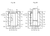
- the lubricating oil 11 is filled into the interior space of the housing 7 (for example, the inner periphery of the bearing sleeve 8) (regarding the above description, see FIG. 5A .
- FIG. 5B when the shaft member 2 is inserted into the annular member 9 and along the inner periphery of the bearing sleeve 8, the fluid dynamic bearing device 1 illustrated in FIG. 2 is completed.
- the radial bearing gaps Gr, Gr are defined between the radial bearing surfaces formed at upper and lower two positions of the inner peripheral surface 8a of the bearing sleeve 8 , and the outer peripheral surface 2a of the shaft member 2 opposed to the radial bearing surfaces. Then, along with rotation of the shaft member 2, pressure of an oil film formed in the both radial bearing gaps Gr, Gr is increased by the dynamic pressure generating action of the radial dynamic pressure generating portions A1, A2, and the radial bearing portions R1, R2 for supporting the shaft member 2 in a non-contact manner in the radial direction are formed at two axial positions.
- the inner bottom surface 7b1 of the housing 7 (the upper end surface of the thrust plate 10) forms the thrust bearing portion T for supporting the shaft member 2 in a contact manner in one thrust direction.
- a magnetic force is applied to the shaft member 2 as an external force for forcing the shaft member 2 downward (to the bottom portion 7b side of the housing 7). Therefore, the shaft member 2 can be prevented from being excessively floated along with rotation of the shaft member 2, and can be also prevented from being removed from the inner periphery of the bearing sleeve 8 as much as possible.
- the void section is formed in the interior space of the housing 7. This means that an amount of the lubricating oil 11 filled into the interior space is smaller than the volume of the interior space.
- the shaft member 2 is insertable into and removable from the bearing sleeve 8 (and the annular member 9).
- This problem can be solved by setting the gap width d 2 of the radial gap Ga so as to satisfy a relationship of 30d 1 ⁇ d 2 when d 1 represents the gap width of the radial bearing gap Gr and d 2 represents the gap width of the radial gap Ga. That is, in this manner, as illustrated in FIG. 5A , it is possible to effectively prevent the lubricating oil 11 from adhering to the inner peripheral surface 9a of the annular member 9 along with insertion of the shaft member 2 along the inner periphery of the bearing sleeve 8, and hence leakage of the lubricating oil to an outside of the housing 7 can be prevented as much as possible.
- the communication path 12 for communicating the radial gap Ga and the bottom gap Gb to each other is formed. Accordingly, even in a case where the shaft member 2 is inserted along the inner periphery of the bearing sleeve 8 after the lubricating oil 11 is injected into the interior space of the housing 7, the air that is pumped into the bottom portion 7b side of the housing 7 along with insertion of the shaft member 2 can be discharged to atmosphere through the communication path 12. Therefore, it is possible to more effectively prevent the lubricating oil 11 from leaking to the outside along with insertion of the shaft member 2.
- an upper limit value of the gap width d 2 of the radial gap Ga is set so as to also satisfy a relationship of d 2 ⁇ 250d 1 .
- the external force for forcing the shaft member 2 to the bottom portion 7b side of the housing 7 (supporting the shaft member 2 in another thrust direction) is applied to the shaft member 2.
- the shaft member 2 can be supported in both the thrust directions, and hence it is possible to increase support accuracy (rotational accuracy) in the thrust directions.
- the external force applied as described above is a magnetic force, and this magnetic force is applied by arranging, with a shift in the axial direction, the stator coils 5 provided to the motor base 6 for holding the housing 7 on its inner periphery, and the rotor magnet 4 provided to the rotor 3.
- Motors having built therein the fluid dynamic bearing device 1 of this type comprise, as essential components, the rotor magnet 4 and the stator coils 5.
- the lubricating oil 11 may leak to the outside through the radial gap Ga, which leads to reduction in bearing performance.
- This problem can be effectively prevented by, for example, (1) forming the radial bearing gap Gr (radial bearing gap Gr at the radial bearing portion R1) having a gap width smaller than the gap width of the radial gap Ga at a position adjacent to the radial gap Ga in the axial direction, (2) forming the radial bearing gaps Gr and the radial dynamic pressure generating portions A1, A2 for generating fluid dynamic pressure in the radial bearing gaps Gr at two axial positions, forming the upper radial dynamic pressure generating portion A1 into such a shape as to pump, into the lower radial bearing gap Gr, the lubricating oil 11 filled in the upper radial bearing gap Gr, and forming the lower radial dynamic pressure generating portion A2 into such a shape as to pump, into the upper radial bearing gap Gr, the lubricating oil 11 filled in the lower radial bearing gap Gr, and (3) selecting and using, as the lubricating oil 11, oil having relatively high viscosity.
- the lubricating oil 11 is drawn into an interior side of the bearing by a capillary force.
- the lubricating oil 11 filled in the radial bearing gaps Gr (in particular, the upper radial bearing gap Gr) can be prevented as much as possible from flowing toward the radial gap Ga. Therefore, reduction in bearing performance due to leakage of the lubricating oil 11 to the outside can be prevented as much as possible so that desired bearing performance can be maintained stably.
- an oil repellent film may be formed on the outer peripheral surface 2a of the shaft member 2 or an upper end surface of the annular member 9, which is adjacent to the radial gap Ga and exposed to the atmosphere.
- the fluid dynamic bearing device 1 according to the embodiment of the present invention is described above, and various modifications may be made to each part of the fluid dynamic bearing device 1 without departing from the gist of the present invention.
- the thrust bearing portion T for supporting the shaft member 2 in the thrust direction can be formed of a so-called fluid dynamic bearing.
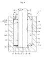
- FIG. 6 illustrates an example of a case where the thrust bearing portion T is formed of a fluid dynamic bearing.
- the lower end surface 2b of the shaft member 2 is formed into a flat surface extending in a direction orthogonal to an axis.
- the dynamic pressure generating portion such as dynamic pressure generating grooves is formed on any one of the lower end surface 2b of the shaft member 2 and the inner bottom surface 7b1 of the bottom portion 7b of the housing 7 opposed to the lower end surface 2b.
- the housing 7 provided separately from the motor base 6 is fixed to the inner periphery of the motor base 6.
- a part corresponding to the motor base 6 may be formed integrally with the housing 7.
- any one of or both of the radial bearing portions R1, R2 may be formed of other publicly known fluid dynamic bearings, such as so-called a multi-lobe bearing, a step bearing, and a wave bearing.
- the thrust bearing portion T is formed of a fluid dynamic bearing ( FIG. 6 )
- the fluid dynamic bearing may comprise other publicly known fluid dynamic bearings, such as so-called a step bearing and a wave bearing.
- the rotor magnet 4 and the stator coils 5 are arranged with a shift in the axial direction so that the external force for forcing the shaft member 2 to the bottom portion 7b side of the housing 7 is applied to the shaft member 2.
- means for applying such an external force to the shaft member 2 is not limited to that in the above description.
- a magnetic member capable of attracting the rotor magnet 4 may be arranged so as to face the rotor magnet 4 in the axial direction so that the magnetic force is applied to the rotor 3.
- the magnetic force (magnetic attraction force) serving as the external force for forcing the shaft member 2 downward need not be generated.
- the present invention is applied to the fluid dynamic bearing device 1 in which the rotor 3 comprising the blades is fixed as a rotary member to the shaft member 2.
- the present invention is suitably applicable also to a fluid dynamic bearing device 1 in which a disk hub having a disk mounting surface or a polygonal mirror is fixed to the shaft member 2 as a rotary member.
- the present invention is suitably applicable not only to the fluid dynamic bearing device 1 built in the fan motor as illustrated in FIG. 1 but also to a fluid dynamic bearing device 1 built in other electrical apparatus such as a spindle motor for disk drives and a polygon scanner motor for laser beam printers (LBPs).
- LBPs laser beam printers
- the test piece according to Example is an assembly including a bearing sleeve having a size of an inner diameter ⁇ of 1.5 mm by an outer diameter ⁇ of 3.0 mm, and configured to define, together with the shaft member, a radial bearing gap having a gap width of 5 ⁇ m, an annular member configured to define, together with the shaft member, a radial gap (Ga) having a gap width of 0.3 mm, and a housing configured to fix the bearing sleeve and the annular member in the state illustrated in FIG. 2 . That is, the test piece according to Example is an assembly including the above-mentioned members, in which the gap width of the radial gap (Ga) is set to sixty times as large as the gap width of the radial bearing gap in view of design.
- the test piece according to Comparative Example is the same as the test piece according to Example except for employing an annular member configured to define, together with the shaft member, a radial gap (Ga) having a gap width of 0.03 mm. That is, the test piece according to Comparative Example is an assembly including the above-mentioned members, in which the gap width of the radial gap (Ga) is set to six times as large as the gap width of the radial bearing gap in view of design.
- Ester-based or PAO-based lubricating oil having kinematic viscosity of 120 mm 2 /s at 20°C, 45 mm 2 /s at 40°C, and 8 mm 2 /s at 100°C is used.
- a filling amount of 3 mg of the lubricating oil is an amount capable of almost achieving the state illustrated in FIG. 2 in the respective test pieces, that is, a state in which the radial bearing gap (Gr) and the bottom gap (Gb) are filled with the lubricating oil.
Abstract
Description
- A present invention relates to a fluid dynamic bearing device and a motor including the fluid dynamic bearing device.
- As is well known, fluid dynamic bearing devices have features in their high speed rotation, high rotational accuracy, quietness, and the like. Thus, the fluid dynamic bearing devices are suitably used as bearing devices for motors to be mounted to various electrical apparatus such as information apparatus, and more specifically, as bearing devices for spindle motors to be built in disk drives of HDDs and the like, for fan motors to be built in PCs and the like, or for polygon scanner motors to be built in laser beam printers (LBPs).
- An example of the fluid dynamic bearing device is disclosed in
Patent Literature 1. The fluid dynamic bearing device includes a housing having a bottomed cylindrical shape (cup shape), a bearing sleeve fixed to an inner periphery of the housing, a shaft member removably inserted along an inner periphery of the bearing sleeve, a radial bearing portion for supporting the shaft member in a radial direction by an oil film of lubricating oil formed in a radial bearing gap, a thrust bearing portion for supporting the shaft member in a thrust direction, a bottom gap having the thrust bearing portion received therein, and an annular member (sealing member) fixed to an inner periphery of an opening portion of the housing. - In the fluid dynamic bearing device, the annular member is fixed to the inner periphery of the opening portion of the housing in a state of engaging with the bearing sleeve in an axial direction (state of engaging with the bearing sleeve in a direction of removing the bearing sleeve). Accordingly, a force for fixing the bearing sleeve to the housing (force for removing the bearing sleeve) is increased, and thus relative positions of the housing and the bearing sleeve in the axial direction, and also desired bearing performance are maintained stably. Further, the fluid dynamic bearing device is used in a so-called fully-filled state in which an entire interior space of the housing is filled with the lubricating oil, and a sealing space (radial gap having a gap width larger than that of the radial bearing gap) is formed between an inner peripheral surface of the annular member and an outer peripheral surface of the shaft member. The sealing space is designed to function as a buffer for absorbing an amount of a volume change accompanied with a temperature change of the lubricating oil, thereby being capable of always maintaining an oil level of the lubricating oil in the sealing space within a range of the assumed temperature change. Therefore, reduction in bearing performance and contamination of peripheral environment, which result from leakage of the lubricating oil to an outside, can be prevented as much as possible.
- Patent Literature 1:
JP 2003-307212 A - However, when the so-called fully-filled structure in which an entire interior space of the housing is filled with the lubricating oil is employed as described above, after assembly of the fluid dynamic bearing device, the interior space of the housing needs to be filled with the lubricating oil by a complicated process such as so-called vacuum impregnation, and the oil level of the lubricating oil needs to be managed with high accuracy (a filling amount of the lubricating oil needs to be finely adjusted). Thus, there has been pointed out a problem of a difficulty in satisfying the demand for further cost reduction of the fluid dynamic bearing device.
- In view of the circumstances, it is an object of the present invention to provide a fluid dynamic bearing device that can be manufactured at low cost and exert desired bearing performance.
- According to one embodiment of the present invention, which is devised to achieve the above-mentioned object, there is provided a fluid dynamic bearing device, comprising: a housing formed into a bottomed cylindrical shape so as to have one open axial end and another closed axial end; a bearing sleeve fixed to an inner periphery of the housing; a shaft member removably inserted along an inner periphery of the bearing sleeve; an annular member having an inner peripheral surface for defining a radial gap together with an outer peripheral surface of the shaft member, the annular member being fixed to an inner periphery of the one open axial end of the housing in a state of engaging with the bearing sleeve in an axial direction; a radial bearing portion for supporting the shaft member in a radial direction by an oil film of lubricating oil, which is formed in a radial bearing gap defined between an inner peripheral surface of the bearing sleeve and the outer peripheral surface of the shaft member; a thrust bearing portion for supporting the shaft member in a thrust direction; and a bottom gap having the thrust bearing portion received therein, and being filled with the lubricating oil, wherein the housing has a void section formed in an interior space thereof, and wherein assuming that d1 represents a gap width of the radial bearing gap and d2 represents a gap width of the radial gap, a relationship of 30d1≤d2≤250d1 is satisfied. Note that, the "thrust bearing portion" described herein may be formed of a pivot bearing for supporting the shaft member in a contact manner, or a fluid dynamic bearing for supporting the shaft member in a non-contact manner.
- In the fluid dynamic bearing device according to the one embodiment of the present invention, in a situation where the radial bearing gap at the radial bearing portion, and the bottom gap having the thrust bearing portion received therein are filled with the lubricating oil, the void section is formed in the interior space of the housing (hereinafter simply referred to also as "interior space"). This means that an amount of the lubricating oil filled into the interior space of the housing is smaller than a volume of the above-mentioned interior space, and that a region filled with no lubricating oil is formed in the above-mentioned interior space. In the fluid dynamic bearing device according to the one embodiment of the present invention, the shaft member is insertable into and removable from the bearing sleeve. With this configuration, for example, only by injecting the lubricating oil into the interior space using an appropriate oil dispenser (such as a micropipette) after the bearing sleeve and the annular member are fixed to the inner periphery of the housing and before the shaft member is inserted along the inner periphery of the bearing sleeve, a necessary amount of the lubricating oil can be filled in the interior space. Therefore, a large-scale device for oil injection and operations to adjust and manage an oil level with high accuracy is not needed, with the result that the bearing device can be manufactured at low cost.
- As described above, in view of structure of the fluid dynamic bearing device according to the one embodiment of the present invention, operations to inject oil into the interior space can be carried out after the bearing sleeve and the annular member are fixed to the inner periphery of the housing and before the shaft member is inserted along the inner periphery of the bearing sleeve. In this case, as compared to a case where oil injection into the interior space is carried out after the shaft member is inserted along the inner periphery of the bearing sleeve, oil injecting operations can be carried out more easily and appropriately. However, in a case where no measure is taken, the lubricating oil is liable to leak along with insertion of the shaft member along the inner periphery of the bearing sleeve after oil injection. A mechanism of occurrence of leakage of the lubricating oil is described with reference to
FIGS. 7A and 7B . - First, as illustrated in
FIG. 7A , abearing sleeve 108 and anannular member 109 are fixed to an inner periphery of ahousing 107 so that abottom gap 105 is defined between a bottom portion of thehousing 107 and thebearing sleeve 108. Then, lubricatingoil 110 is injected into an interior space of thehousing 107. Next, as illustrated inFIG. 7B , ashaft member 102 is inserted into theannular member 109 and along an inner periphery of thebearing sleeve 108. When theshaft member 102 comes into contact with the lubricatingoil 110 injected in advance, the lubricatingoil 110 flows by a capillary force toward an opening portion of thehousing 107 through a radial gap (radial bearing gap) defined between (an outer peripheral surface of) theshaft member 102 and (an inner peripheral surface of) thebearing sleeve 108 so as to have a minute gap width. Then, the lubricatingoil 110 adheres to the outer peripheral surface of theshaft member 102, and also to an inner peripheral surface of theannular member 109. Along with progress of insertion of theshaft member 102, the air present in the interior space of the housing 107 (between theshaft member 102 and the housing 107) is compressed. As a result, an urging force for pushing out the lubricatingoil 110 toward an outside of the bearing is applied to the lubricatingoil 110 filled between theshaft member 102 and thebearing sleeve 108 and between theshaft member 102 and theannular member 109. In this manner, the lubricatingoil 110 leaks to the outside of the bearing through the radial gap (sealing space) 103 defined between the outer peripheral surface of theshaft member 102 and the inner peripheral surface of theannular member 109. In this case, a sufficient amount of the lubricating oil cannot be filled both in the radial bearing gap and thebottom gap 105, with the result that it is difficult to stably ensure desired bearing performance. - According to studies diligently conducted by the inventors of the present invention, the following has been found as a result. That is, when d2 represents a gap width of the radial gap, in a case where a value of d2 exceeds a predetermined value, the lubricating oil can be prevented as much as possible from adhering to the inner peripheral surface of the annular member along with insertion of the shaft member, and leakage of the lubricating oil in the above-mentioned manner can be prevented as much as possible. Specifically, it has been found that the leakage can be solved in such a manner that, when d1 represents a gap width of the radial bearing gap and d2 represents a gap width of the radial gap, the gap width d2 of the radial gap is set so as to satisfy a relationship of 30d1≤d2. Thus, assembly of the bearing device and oil injection into the bearing device can be carried out easily, and the fluid dynamic bearing device can be manufactured at low cost. However, when the gap width d2 of the radial gap is set to an extremely large size, a contact area between the bearing sleeve and the annular member is extremely small, and hence it may be difficult to ensure a necessary force for removing the bearing sleeve. Therefore, it is preferred that a relationship of d2≤250d1 be satisfied.
- The bearing device having the above-mentioned configuration may further comprise a communication path for communicating the radial gap and the bottom gap to each other. With this, even in a case where the shaft member is inserted along the inner periphery of the bearing sleeve after the lubricating oil is injected into the interior space, the air that is pumped into the bottom gap side along with insertion of the shaft member can be discharged to atmosphere through the communication path, and hence it is possible to more effectively prevent the lubricating oil from leaking to the outside along with insertion of the shaft member. Note that, at least a part of the communication path is employed as the above-mentioned void section.
- The above-mentioned communication path may comprise: a first path formed between the housing and the bearing sleeve so as to have one end that is open to the bottom gap; and a second path formed between the bearing sleeve and the annular member so as to have one end that is open to the radial gap, and another end that is continuous with another end of the first path.
- The bearing sleeve can be fixed to the inner periphery of the housing by, for example, press fitting (specifically, press fitting with a large interference, the same is true for the following means), bonding, or press-fit bonding (combination of press fitting and bonding). However, in press fitting, deformation of the bearing sleeve accompanied with press fitting affects an inner peripheral surface of the bearing sleeve, and may exert an adverse influence on width accuracy of the radial bearing gap. Further, in bonding, it is necessary to relatively position the housing and the bearing sleeve and retain the housing and the bearing sleeve until an applied adhesive is cured, and in addition, it is sometimes necessary to provide another process of curing the adhesive. Accordingly, time and effort are required for fixing both the members. In this context, the bearing sleeve is fixed to the inner periphery of the housing while being sandwiched from both axial sides thereof between the annular member and the bottom portion of the housing. In this manner, it is possible to reduce time and effort necessary for assembly. In addition, exertion of an adverse influence on bearing performance of the radial bearing portion can be prevented as much as possible.
- In the above-mentioned configuration, the radial bearing gap may be formed at two axial positions. In this case, radial dynamic pressure generating portions for causing dynamic pressure generating action in the lubricating oil in the radial bearing gaps may be formed also at two axial positions. With this configuration, it is possible to increase load capacity (moment rigidity) to moment load while reducing loss torque. At this time, it is desired that one of the radial dynamic pressure generating portions be formed into such a shape as to pump the lubricating oil, which is filled in one of the radial bearing gaps, into another one of the radial bearing gaps, and that another one of the radial dynamic pressure generating portions be formed into such a shape as to pump the lubricating oil, which is filled in the another one of the radial bearing gaps, into the one of the radial bearing gaps. With this configuration, while preventing as much as possible reduction in bearing performance of the radial bearing portion due to shortage of the oil film in each radial bearing gap, the lubricating oil filled in the radial bearing gaps can be prevented from flowing toward the above-mentioned radial gap, and in addition, the lubricating oil can be prevented from leaking to the outside as much as possible.
- In the above-mentioned configuration, the shaft member may be subjected to an external force for forcing the shaft member to an inner bottom surface of the housing. With this, the shaft member can be supported in both thrust directions, and hence support accuracy in the thrust directions is increased. In addition, the present invention has an advantage in preventing unintended removal of the shaft member that is removably inserted into the bearing sleeve. As an example of the external force described above, a magnetic force may be applied. This magnetic force can be applied, for example, by arranging, with a shift in the axial direction, stator coils provided to a holding member (motor base) for holding the housing on its inner periphery, and a rotor magnet provided to the shaft member. Normally, various motors having built therein the fluid dynamic bearing device of this type comprise, as essential components, the rotor magnet and the stator coils. Thus, when the above-mentioned configuration is employed, the external force can be inexpensively applied without involving a significant cost increase.
- It is preferred that the bearing sleeve comprise a porous body having internal pores impregnated with the above-mentioned lubricating oil. With this, the lubricating oil seeps out of the pores in a surface of the bearing sleeve, and hence both the radial bearing gap and the bottom gap can be filled with a sufficient amount of the lubricating oil. Thus, the present invention is advantageous in stably maintaining bearing performance of the radial bearing portions and the thrust bearing portion.
- It is preferred that the lubricating oil, which is used in the fluid dynamic bearing device according to the one embodiment of the present invention, comprise ester-based or PAO-based lubricating oil having kinematic viscosity of 20 to 90 mm2/s at 40°C, and surface tension of 29 to 31 mN/m at 20°C.
- As described above, the fluid dynamic bearing device according to one embodiment of the present invention has the above-mentioned various features. Thus, the fluid dynamic bearing device can be suitably used by being built in various motors such as a fan motor for PCs and a spindle motor for disk drives, and can also contribute to cost reduction of those various motors.
- As described above, according to the one embodiment of the present invention, it is possible to provide the fluid dynamic bearing device that can be manufactured at low cost and exert desired bearing performance.
-
-
FIG. 1 is a schematic cross-sectional view illustrating a structural example of a fan motor. -
FIG. 2 is a cross-sectional view illustrating a fluid dynamic bearing device according to a first embodiment of the present invention. -
FIG. 3 is a cross-sectional view illustrating a bearing sleeve illustrated inFIG. 2 . -
FIG. 4 is an enlarged cross-sectional view illustrating a main part of the fluid dynamic bearing device illustrated inFIG. 2 . -
FIG. 5A is a view illustrating an initial stage of a process of assembling the fluid dynamic bearing device illustrated inFIG. 2 . -
FIG. 5B is a view illustrating an intermediate stage of the process of assembling the fluid dynamic bearing device illustrated inFIG. 2 . -
FIG. 6 is a cross-sectional view illustrating a fluid dynamic bearing device according to a second embodiment of the present invention. -
FIG. 7A is a view illustrating an initial stage of a process of assembling a related-art fluid dynamic bearing device. -
FIG. 7B is a view illustrating an intermediate stage of the process of assembling the related-art fluid dynamic bearing device. - Now, description is made of an embodiment of the present invention with reference to the drawings.
-
FIG. 1 schematically illustrates a structural example of a fan motor having built therein a fluiddynamic bearing device 1 according to the present invention. The fan motor illustrated inFIG. 1 comprises the fluiddynamic bearing device 1, amotor base 6 serving as a holding member on a stationary side of the motor, stator coils 5 mounted to themotor base 6, arotor 3 serving as a rotary member and comprising blades (not shown), and arotor magnet 4 being mounted to therotor 3 and facing the stator coils 5 across a radial gap. Ahousing 7 of the fluiddynamic bearing device 1 is fixed to an inner periphery of themotor base 6, and therotor 3 is fixed to one end of ashaft member 2 of the fluiddynamic bearing device 1. In the fan motor having such a structure, when the stator coils 5 are energized, an electromagnetic force is generated between the stator coils 5 and therotor magnet 4 so as to cause therotor magnet 4 to rotate. In conjunction therewith, theshaft member 2 and therotor 3 fixed to theshaft member 2 are integrally rotated. - Note that, when the
rotor 3 is rotated, wind is blown upward or downward inFIG. 1 depending on a form of the blades provided to therotor 3. Thus, during rotation of therotor 3, a reactive force of this blowing action is applied as an upward or downward thrust force inFIG. 1 to theshaft member 2 of the fluiddynamic bearing device 1. In a region between the stator coils 5 and therotor magnet 4, a magnetic force (repulsive force) is applied in a direction in which the thrust force is counterbalanced. A thrust load, which is generated by a difference in magnitude between the thrust force and the magnetic force, is supported by a thrust bearing portion T of the fluiddynamic bearing device 1. The magnetic force in the direction in which the thrust force is counterbalanced can be generated, for example, by arranging the stator coils 5 and therotor magnet 4 with a shift in the axial direction (not shown in detail). Further, during the rotation of therotor 3, a radial load is applied to theshaft member 2 of the fluiddynamic bearing device 1. This radial load is supported by radial bearing portions R1, R2 of the fluiddynamic bearing device 1. -
FIG. 2 illustrates the fluiddynamic bearing device 1 according to the embodiment of the present invention. The fluiddynamic bearing device 1 comprises, as main components, thehousing 7 having a bottomed cylindrical shape, abearing sleeve 8 fixed to an inner periphery of thehousing 7, theshaft member 2 inserted along an inner periphery of thebearing sleeve 8, and anannular member 9 fixed to the inner periphery of thehousing 7 on an opening side of thehousing 7 with respect to thebearing sleeve 8. An interior space of thehousing 7 is filled with a predetermined amount of lubricating oil 11 (indicated by densely dotted hatching). At least a radial bearing gap Gr (seeFIG. 4 ) at each of the radial bearing portions R1, R2 for supporting theshaft member 2 in a radial direction, and a bottom gap Gb having received therein the thrust bearing portion T for supporting theshaft member 2 in a thrust direction are filled with the lubricatingoil 11. Note that, in the following description, for the sake of convenience of description, a side on which theannular member 9 is arranged is hereinafter referred to as an upper side, and an opposite side in an axial direction is hereinafter referred to as a lower side. However, this definition does not limit a posture of the fluiddynamic bearing device 1 in use. - The
housing 7 has the bottomed cylindrical shape comprising a circularcylindrical portion 7a and abottom portion 7b closing a lower end opening of thecylindrical portion 7a. In this case, the circularcylindrical portion 7a and thebottom portion 7b are integrally made of metal. On an inner periphery of a boundary portion between thecylindrical portion 7a and thebottom portion 7b, a steppedportion 7c is formed integrally with thecylindrical portion 7a and thebottom portion 7b. (A radially outer region of) alower end surface 8b of thebearing sleeve 8 abuts on an upper end surface 7c1 of the steppedportion 7c. In this embodiment, athrust plate 10 made of, for example, a resin is arranged in a region of an inner bottom surface 7b1 of thehousing 7 serving as a thrust bearing surface. However, it is not always necessary to provide thethrust plate 10, and thethrust plate 10 may be omitted. Thehousing 7 may be also obtained by injection molding of a resin. - The
shaft member 2 is made of a metal material having high rigidity, which is typified by stainless steel. An outerperipheral surface 2a of theshaft member 2 is formed into a smooth cylindrical surface, and theshaft member 2 is formed so as to have a uniform diameter over its entire length. An outer diameter dimension of theshaft member 2 is smaller than inner diameter dimensions of thebearing sleeve 8 and theannular member 9. Therefore, theshaft member 2 is insertable into and removable from the bearingsleeve 8 and theannular member 9. Alower end surface 2b of theshaft member 2 is formed into a convex spherical surface, and is held in contact with the inner bottom surface 7b1 of the housing 7 (an upper end surface of the thrust plate 10). Therotor 3 comprising blades is fixed to an upper end of the shaft member 2 (seeFIG. 1 ). - The
bearing sleeve 8 is obtained by forming a porous body, specifically, a porous body of sintered metal containing, as a main component, copper powder (including copper-based alloy powder) or iron powder (iron-based alloy powder) into a cylindrical shape. The above-mentionedlubricating oil 11 is impregnated into internal pores of thebearing sleeve 8. Thebearing sleeve 8 is not always formed of a porous body of sintered metal, and may be formed of other porous bodies such as a porous resin. Thebearing sleeve 8 is fixed to the inner periphery of thehousing 7 under a state in which thelower end surface 8b of thebearing sleeve 8 abuts on the upper end surface 7c1 of the steppedportion 7c of thehousing 7. With this, relative positions of thehousing 7 and thebearing sleeve 8 in the axial direction are determined, and the bottom gap Gb having a predetermined volume is formed between thelower end surface 8b of thebearing sleeve 8 and the inner bottom surface 7b1 of the housing 7 (the upper end surface of the thrust plate 10). - The
bearing sleeve 8 can be fixed to the inner periphery of thehousing 7 by appropriate means such as press fitting (press fitting with a large interference), bonding, and press-fit bonding (combination of press fitting and bonding). However, in this embodiment, thebearing sleeve 8 is fixed to the inner periphery of thehousing 7 by being sandwiched from both axial sides thereof between theannular member 9 and (the steppedportion 7c formed at a radially outer end of) thebottom portion 7b of thehousing 7. In this manner, theannular member 9 is fixed to thehousing 7, and at the same time, thebearing sleeve 8 can be fixed to thehousing 7. Accordingly, it is possible to reduce time and effort necessary for assembly of members. Further, when thebearing sleeve 8 is press-fitted with a large interference to the inner periphery of themetal housing 7 according to this embodiment, deformation of thebearing sleeve 8 accompanied with press fitting affects an innerperipheral surface 8a of thebearing sleeve 8, and may exert an adverse influence on width accuracy of the radial bearing gap Gr, and bearing performance of the radial bearing portions R1, R2 as well. However, with the above-mentioned fixing method, this adverse influence can be prevented as much as possible. - Cylindrical radial bearing surfaces are formed at two axial positions on the inner
peripheral surface 8a of thebearing sleeve 8. The cylindrical radial bearing surfaces define the radial bearing gaps Gr (seeFIG. 4 ) together with the outerperipheral surface 2a of theshaft member 2 opposed to the innerperipheral surface 8a. As illustrated inFIG. 3 , on the radial bearing surfaces, dynamic pressure generating portions (radial dynamic pressure generating portions) A1, A2 for causing dynamic pressure generating action in the lubricatingoil 11 in the radial bearing gaps are formed, respectively. The radial dynamic pressure generating portions A1, A2 according to this embodiment each comprise a plurality of upper dynamic pressure generating grooves Aa1 and a plurality of lower dynamic pressure generating grooves Aa2 that are inclined in opposite directions and spaced apart from each other in the axial direction, and convex hill portions that partition both the dynamic pressure generating grooves Aa1, Aa2. The radial dynamic pressure generating portions A1, A2 each exhibit a herringbone shape as a whole. The hill portions according to this embodiment comprise inclined hill portions Ab formed between the dynamic pressure generating grooves that are adjacent to each other in a circumferential direction, and annular hill portions Ac formed between the upper dynamic pressure generating grooves Aa1 and the lower dynamic pressure generating grooves Aa2 so as to have substantially the same diameter as that of the inclined hill portions Ab. - In the upper radial dynamic pressure generating portion A1, an axial dimension of the upper dynamic pressure generating grooves Aa1 is larger than an axial dimension of the lower dynamic pressure generating grooves Aa2. On the other hand, in the lower radial dynamic pressure generating portion A2, an axial dimension of the lower dynamic pressure generating grooves Aa2 is larger than an axial dimension of the upper dynamic pressure generating grooves Aa1. In addition, the axial dimension of the upper dynamic pressure generating grooves Aa1 forming the radial dynamic pressure generating portion A1 is equal to the axial dimension of the lower dynamic pressure generating grooves Aa2 forming the radial dynamic pressure generating portion A2. Further, the axial dimension of the lower dynamic pressure generating grooves Aa2 forming the radial dynamic pressure generating portion A1 is equal to the axial dimension of the upper dynamic pressure generating grooves Aa1 forming the radial dynamic pressure generating portion A2. Therefore, during rotation of the
shaft member 2, the lubricatingoil 11 filled in the upper radial bearing gap Gr (radial bearing portion R1) and the lubricatingoil 11 filled in the lower radial bearing gap Gr (radial bearing portion R2) are pumped into the lower and upper radial bearing gaps, respectively. - Note that, the radial dynamic pressure generating portions A1, A2 may be molded, for example, simultaneously with molding of the bearing sleeve 8 (specifically, simultaneously with molding of the
bearing sleeve 8 into a final dimension by a sizing process on a bearing preform obtained by compacting and sintering metal powder), or may be formed by plastic working such as rolling on a bearing preform having a smooth and cylindrical inner peripheral surface in view of satisfactory processability of the sintered metal. Further, modes of the radial dynamic pressure generating portions A1, A2 (dynamic pressure generating grooves) are not limited thereto. For example, in any one of or both of the radial dynamic pressure generating portions A1, A2, a plurality of dynamic pressure generating grooves may be arrayed in a spiral pattern in the circumferential direction. Any one of or both of the radial dynamic pressure generating portions A1, A2 may be formed on the outerperipheral surface 2a of theshaft member 2 opposed to thebearing sleeve 8. - The
annular member 9 made of metal or a resin and formed into a ring shape is fixed to an upper end portion of an inner peripheral surface 7a1 of thehousing 7 by appropriate means such as bonding, press fitting, and press-fit bonding. A radial gap Ga is defined between an innerperipheral surface 9a of theannular member 9 and the outerperipheral surface 2a of theshaft member 2 opposed to the innerperipheral surface 9a. An upper side of thebearing sleeve 8 is open to atmosphere through the radial gap Ga. - As illustrated in
FIG. 4 in an enlarged manner, a gap width d2 of the radial gap Ga is set to be larger than a gap width d1 of the radial bearing gap Gr at each of the radial bearing portions R1, R2 (the radial bearing portion R2 is not shown inFIG. 4 ). Specifically, the inner diameter dimension of theannular member 9 is adjusted so as to satisfy a relationship of 30d1≤d2. Note that, the gap width d1 of the radial bearing gap Gr is set depending on required bearing performance, and is often set to about a few micrometers, more specifically, 2 to 10 µm under normal conditions (inFIG. 4 , illustration of the gap width d1 of the radial bearing gap Gr is exaggerated). Therefore, for example, in a case where the gap width d1 of the radial bearing gap Gr is set to 10 µm, the gap width d2 of the radial gap Ga is set to 300 µm (0.30 mm) or more. - On the other hand, as described above, the
annular member 9 functions as a fixing member for fixing thebearing sleeve 8 to thehousing 7. Thus, setting of the gap width d2 of the radial gap Ga to an extremely large size leads to reduction in force for fixing thebearing sleeve 8 to thehousing 7. Accordingly, the gap width d2 of the radial gap Ga is set so as to also satisfy a relationship of d2≤250d1. Note that, from a different point of view, assuming that d3 represents a radial thickness of thebearing sleeve 8, the gap width d2 of the radial gap Ga is set so as to also satisfy a relationship of d2≤d3/2. For example, in a case of using thebearing sleeve 8 having a radial thickness d3 of 0.8 mm, the gap width d2 of the radial gap Ga is set to 0.4 mm or less. - The fluid
dynamic bearing device 1 comprises acommunication path 12 for communicating the radial gap Ga and the bottom gap Gb to each other. Thecommunication path 12 comprises afirst path 12a formed between thehousing 7 and thebearing sleeve 8 so as to have one end that is open to the bottom gap Gb, and asecond path 12b formed between thebearing sleeve 8 and theannular member 9 so as to have one end that is open to the radial gap Ga, and another end that is continuous with another end of thefirst path 12a. In this case, the above-mentionedfirst path 12a comprises an axial fluid path, which is defined by the inner peripheral surface 7a1 of the housing 7 (cylindrical portion 7a) and one or a plurality of axial grooves 8d1 formed in an outerperipheral surface 8d of thebearing sleeve 8, and a radial fluid path, which is defined by the upper end surface 7c1 of the stepped portion of thehousing 7 and one or a plurality of radial grooves 8b1 formed in thelower end surface 8b of thebearing sleeve 8. Further, the above-mentionedsecond path 12b comprises a radial fluid path defined by alower end surface 9b of theannular member 9 and one or a plurality of radial grooves 8c1 formed in anupper end surface 8c of thebearing sleeve 8. - Under a state in which the fluid
dynamic bearing device 1 having the above-mentioned configuration is arranged in a posture illustrated inFIG. 2 , of the interior space of thehousing 7, at least the radial bearing gap Gr (radial gap defined between the outerperipheral surface 2a of theshaft member 2 and the innerperipheral surface 8a of the bearing sleeve 8) at each of the radial bearing portions R1, R2, and the bottom gap Gb having the thrust bearing portion T received therein are filled with the lubricatingoil 11. In addition, in this embodiment, the radial groove 8c1 formed in thelower end surface 8c of thebearing sleeve 8, an annular space defined by a lower end outer circumferential chamfer of thebearing sleeve 8, and the radial gap (annular space) defined between an upper end inner circumferential chamfer of thebearing sleeve 8 and the outerperipheral surface 2a of theshaft member 2 are also filled with the lubricating oil 11 (seeFIG. 2 ). On the other hand, a part of thecommunication path 12 is not filled with the lubricatingoil 11. Specifically, the axial groove 8d1 (a part of thefirst path 12a) formed in the outerperipheral surface 8d of thebearing sleeve 8, an annular space defined by an upper end outer circumferential chamfer of thebearing sleeve 8, and the radial groove 8c1 (second path 12b) formed in theupper end surface 8c of thebearing sleeve 8 are not filled with the lubricatingoil 11. - With reference to the above description, in the fluid
dynamic bearing device 1, an amount (volume) of the lubricatingoil 11 filled in the interior space of thehousing 7 is smaller than a volume of the interior space of thehousing 7. Therefore, in the interior space of the fluid dynamic bearing device 1 (housing 7), there is formed a void section in which the lubricatingoil 11 is not filled. In this embodiment, the void section is formed in the part of thecommunication path 12. - In this case, in consideration of a temperature change and the like during use and transportation of the fluid
dynamic bearing device 1, as the lubricatingoil 11, ester-based or poly-alpha-olefin-based (PAO-based) lubricating oil is suitably used. In particular, in the fluiddynamic bearing device 1, the gap width d2 of the radial gap Ga formed in the opening portion of thehousing 7 is larger than that of the related-art fluid dynamic bearing device (for example, the fluid dynamic bearing device disclosed in Patent Literature 1), and hence the lubricating oil may leak through the radial gap Ga more easily than in the related art. Accordingly, there is suitably used ester-based or PAO-based lubricating oil having kinematic viscosity of 20 to 90 mm2/s at 40°C, and surface tension of 29 to 31 mN/m at 20°C. - The fluid
dynamic bearing device 1 having the above-mentioned configuration is assembled in the following procedures. - First, until the
lower end surface 8b of thebearing sleeve 8 is brought into abutment on the upper end surface 7c1 of the steppedportion 7c of thehousing 7, thebearing sleeve 8 is lightly press-fitted or loosely fitted to the inner periphery of thehousing 7. Next, under a state in which thelower end surface 9b of theannular member 9 abuts on theupper end surface 8c of thebearing sleeve 8, theannular member 9 is fixed to the upper end portion of the inner peripheral surface 7a1 of thehousing 7. In this manner, thebearing sleeve 8 is fixed to the inner periphery of thehousing 7 so as to be sandwiched from the both axial sides thereof between theannular member 9 and thebottomportion 7b (steppedportion 7c) of thehousing 7. Next, in order to fill respective portions of the interior space of thehousing 7 with the lubricatingoil 11 under the above-mentioned state, the lubricatingoil 11 is filled into the interior space of the housing 7 (for example, the inner periphery of the bearing sleeve 8) (regarding the above description, seeFIG. 5A . As illustrated inFIG. 5B , when theshaft member 2 is inserted into theannular member 9 and along the inner periphery of thebearing sleeve 8, the fluiddynamic bearing device 1 illustrated inFIG. 2 is completed. - In the fluid
dynamic bearing device 1 having the above-mentioned configuration, when theshaft member 2 is rotated, the radial bearing gaps Gr, Gr are defined between the radial bearing surfaces formed at upper and lower two positions of the innerperipheral surface 8a of thebearing sleeve 8 , and the outerperipheral surface 2a of theshaft member 2 opposed to the radial bearing surfaces. Then, along with rotation of theshaft member 2, pressure of an oil film formed in the both radial bearing gaps Gr, Gr is increased by the dynamic pressure generating action of the radial dynamic pressure generating portions A1, A2, and the radial bearing portions R1, R2 for supporting theshaft member 2 in a non-contact manner in the radial direction are formed at two axial positions. At the same time, the inner bottom surface 7b1 of the housing 7 (the upper end surface of the thrust plate 10) forms the thrust bearing portion T for supporting theshaft member 2 in a contact manner in one thrust direction. Note that, as described with reference toFIG. 1 , a magnetic force is applied to theshaft member 2 as an external force for forcing theshaft member 2 downward (to thebottom portion 7b side of the housing 7). Therefore, theshaft member 2 can be prevented from being excessively floated along with rotation of theshaft member 2, and can be also prevented from being removed from the inner periphery of thebearing sleeve 8 as much as possible. - As described above, in the fluid
dynamic bearing device 1 according to the present invention, in a situation where the radial bearing gaps Gr and the bottom gap Gb are filled with the lubricating oil 11 (FIG. 2 ), the void section is formed in the interior space of thehousing 7. This means that an amount of the lubricatingoil 11 filled into the interior space is smaller than the volume of the interior space. In the fluiddynamic bearing device 1 according to the present invention, theshaft member 2 is insertable into and removable from the bearing sleeve 8 (and the annular member 9). Accordingly, as described above, only by filling the lubricatingoil 11 into the interior space of thehousing 7 using an appropriate oil dispenser after thebearing sleeve 8 and theannular member 9 are fixed to the inner periphery of thehousing 7 and before theshaft member 2 is inserted along the inner periphery of thebearing sleeve 8, a necessary amount of the lubricatingoil 11 can be filled in the interior space of thehousing 7. Thus, large-scale device for oil injection and operations to adjust and manage an oil level with high accuracy is not needed, with the result that the fluiddynamic bearing device 1 can be manufactured at low cost. - When oil injection into the interior space of the
housing 7 is carried out in the above-mentioned procedures, as compared to a case where oil injection into the interior space of thehousing 7 is carried out after theshaft member 2 is inserted along the inner periphery of thebearing sleeve 8, oil injecting operations can be carried out more easily and appropriately. However, in a case where no measure is taken, as described with reference toFIGS. 7A and 7B , during insertion of theshaft member 2 along the inner periphery of thebearing sleeve 8, which is carried out after the oil injection, the lubricatingoil 11 is liable to leak to an outside of the device through the radial gap Ga defined by the innerperipheral surface 9a of theannular member 9. - This problem can be solved by setting the gap width d2 of the radial gap Ga so as to satisfy a relationship of 30d1≤d2 when d1 represents the gap width of the radial bearing gap Gr and d2 represents the gap width of the radial gap Ga. That is, in this manner, as illustrated in
FIG. 5A , it is possible to effectively prevent the lubricatingoil 11 from adhering to the innerperipheral surface 9a of theannular member 9 along with insertion of theshaft member 2 along the inner periphery of thebearing sleeve 8, and hence leakage of the lubricating oil to an outside of thehousing 7 can be prevented as much as possible. In addition, in this embodiment, thecommunication path 12 for communicating the radial gap Ga and the bottom gap Gb to each other is formed. Accordingly, even in a case where theshaft member 2 is inserted along the inner periphery of thebearing sleeve 8 after the lubricatingoil 11 is injected into the interior space of thehousing 7, the air that is pumped into thebottom portion 7b side of thehousing 7 along with insertion of theshaft member 2 can be discharged to atmosphere through thecommunication path 12. Therefore, it is possible to more effectively prevent the lubricatingoil 11 from leaking to the outside along with insertion of theshaft member 2. - With reference to the above description, assembly of the fluid
dynamic bearing device 1, and operations to inject oil into the interior space of thehousing 7 can be carried out easily, with the result that the fluiddynamic bearing device 1 can be manufactured at low cost. However, when the gap width d2 of the radial gap Ga is set to an extremely large size, a contact area between theupper end surface 8c of thebearing sleeve 8 and thelower end surface 9b of theannular member 9 is small, which brings a difficulty in ensuring a necessary force for removing thebearing sleeve 8. Therefore, as described above, an upper limit value of the gap width d2 of the radial gap Ga is set so as to also satisfy a relationship of d2≤250d1. - Further, the external force for forcing the
shaft member 2 to thebottom portion 7b side of the housing 7 (supporting theshaft member 2 in another thrust direction) is applied to theshaft member 2. With this, theshaft member 2 can be supported in both the thrust directions, and hence it is possible to increase support accuracy (rotational accuracy) in the thrust directions. In this embodiment, the external force applied as described above is a magnetic force, and this magnetic force is applied by arranging, with a shift in the axial direction, the stator coils 5 provided to themotor base 6 for holding thehousing 7 on its inner periphery, and therotor magnet 4 provided to therotor 3. Motors having built therein the fluiddynamic bearing device 1 of this type comprise, as essential components, therotor magnet 4 and the stator coils 5. Thus, when the above-mentioned configuration is employed, the external force can be inexpensively applied without involving a significant cost increase. - In the configuration of the fluid
dynamic bearing device 1 according to the present invention, for example, in a case where thebearing device 1 in the posture illustrated inFIG. 2 is used upside down, the lubricatingoil 11 may leak to the outside through the radial gap Ga, which leads to reduction in bearing performance. This problem can be effectively prevented by, for example, (1) forming the radial bearing gap Gr (radial bearing gap Gr at the radial bearing portion R1) having a gap width smaller than the gap width of the radial gap Ga at a position adjacent to the radial gap Ga in the axial direction, (2) forming the radial bearing gaps Gr and the radial dynamic pressure generating portions A1, A2 for generating fluid dynamic pressure in the radial bearing gaps Gr at two axial positions, forming the upper radial dynamic pressure generating portion A1 into such a shape as to pump, into the lower radial bearing gap Gr, the lubricatingoil 11 filled in the upper radial bearing gap Gr, and forming the lower radial dynamic pressure generating portion A2 into such a shape as to pump, into the upper radial bearing gap Gr, the lubricatingoil 11 filled in the lower radial bearing gap Gr, and (3) selecting and using, as the lubricatingoil 11, oil having relatively high viscosity. That is, specifically, with the above-mentioned configuration (1), the lubricatingoil 11 is drawn into an interior side of the bearing by a capillary force. With the above-mentioned configuration (2), the lubricatingoil 11 filled in the radial bearing gaps Gr (in particular, the upper radial bearing gap Gr) can be prevented as much as possible from flowing toward the radial gap Ga. Therefore, reduction in bearing performance due to leakage of the lubricatingoil 11 to the outside can be prevented as much as possible so that desired bearing performance can be maintained stably. - Note that, although not shown, in order to more effectively prevent the leakage of the lubricating oil through the radial gap Ga, an oil repellent film may be formed on the outer
peripheral surface 2a of theshaft member 2 or an upper end surface of theannular member 9, which is adjacent to the radial gap Ga and exposed to the atmosphere. - The fluid
dynamic bearing device 1 according to the embodiment of the present invention is described above, and various modifications may be made to each part of the fluiddynamic bearing device 1 without departing from the gist of the present invention. - For example, the thrust bearing portion T for supporting the
shaft member 2 in the thrust direction (one direction) can be formed of a so-called fluid dynamic bearing.FIG. 6 illustrates an example of a case where the thrust bearing portion T is formed of a fluid dynamic bearing. In this case, thelower end surface 2b of theshaft member 2 is formed into a flat surface extending in a direction orthogonal to an axis. Although not shown, the dynamic pressure generating portion (thrust dynamic pressure generating portion) such as dynamic pressure generating grooves is formed on any one of thelower end surface 2b of theshaft member 2 and the inner bottom surface 7b1 of thebottom portion 7b of thehousing 7 opposed to thelower end surface 2b. - Further, in the embodiment described above, the
housing 7 provided separately from themotor base 6 is fixed to the inner periphery of themotor base 6. However, a part corresponding to themotor base 6 may be formed integrally with thehousing 7. - Further, any one of or both of the radial bearing portions R1, R2 may be formed of other publicly known fluid dynamic bearings, such as so-called a multi-lobe bearing, a step bearing, and a wave bearing. Further, in a case where the thrust bearing portion T is formed of a fluid dynamic bearing (
FIG. 6 ), the fluid dynamic bearing may comprise other publicly known fluid dynamic bearings, such as so-called a step bearing and a wave bearing. - Further, in the embodiment described above, the
rotor magnet 4 and the stator coils 5 are arranged with a shift in the axial direction so that the external force for forcing theshaft member 2 to thebottom portion 7b side of thehousing 7 is applied to theshaft member 2. However, means for applying such an external force to theshaft member 2 is not limited to that in the above description. For example, although not shown, a magnetic member capable of attracting therotor magnet 4 may be arranged so as to face therotor magnet 4 in the axial direction so that the magnetic force is applied to therotor 3. Alternatively, in a case where the thrust force serving as the reactive force for the blowing action is great enough to cause theshaft member 2 to be forced downward due to the thrust force alone, the magnetic force (magnetic attraction force) serving as the external force for forcing theshaft member 2 downward need not be generated. - Further, in the case described above, the present invention is applied to the fluid
dynamic bearing device 1 in which therotor 3 comprising the blades is fixed as a rotary member to theshaft member 2. However, the present invention is suitably applicable also to a fluiddynamic bearing device 1 in which a disk hub having a disk mounting surface or a polygonal mirror is fixed to theshaft member 2 as a rotary member. In other words, the present invention is suitably applicable not only to the fluiddynamic bearing device 1 built in the fan motor as illustrated inFIG. 1 but also to a fluiddynamic bearing device 1 built in other electrical apparatus such as a spindle motor for disk drives and a polygon scanner motor for laser beam printers (LBPs). - In order to prove usefulness of the present invention, first, there were prepared a test piece according to Example, which had the configuration of the present invention, and a test piece according to Comparative Example, which did not have the configuration of the present invention. Further, a predetermined amount (3 mg) of lubricating oil was filled into an interior space of each of the test pieces, and then whether or not the lubricating oil leaked to the outside during insertion of the shaft member was confirmed. Details of (A) the test piece according to Example, (B) the test piece according to Comparative Example, and (C) the lubricating oil used in the confirmatory test are as follows.
- The test piece according to Example is an assembly including a bearing sleeve having a size of an inner diameter ϕ of 1.5 mm by an outer diameter ϕ of 3.0 mm, and configured to define, together with the shaft member, a radial bearing gap having a gap width of 5 µm, an annular member configured to define, together with the shaft member, a radial gap (Ga) having a gap width of 0.3 mm, and a housing configured to fix the bearing sleeve and the annular member in the state illustrated in
FIG. 2 . That is, the test piece according to Example is an assembly including the above-mentioned members, in which the gap width of the radial gap (Ga) is set to sixty times as large as the gap width of the radial bearing gap in view of design. - The test piece according to Comparative Example is the same as the test piece according to Example except for employing an annular member configured to define, together with the shaft member, a radial gap (Ga) having a gap width of 0.03 mm. That is, the test piece according to Comparative Example is an assembly including the above-mentioned members, in which the gap width of the radial gap (Ga) is set to six times as large as the gap width of the radial bearing gap in view of design.
- Ester-based or PAO-based lubricating oil having kinematic viscosity of 120 mm2/s at 20°C, 45 mm2/s at 40°C, and 8 mm2/s at 100°C is used.
- A filling amount of 3 mg of the lubricating oil is an amount capable of almost achieving the state illustrated in
FIG. 2 in the respective test pieces, that is, a state in which the radial bearing gap (Gr) and the bottom gap (Gb) are filled with the lubricating oil. - When the shaft member was inserted into the test piece according to Example, the lubricating oil did not adhere to any part of an inner peripheral surface of the annular member from start of insertion until finish of insertion. Therefore, even at a point in time when insertion of the shaft member was completed, the lubricating oil did not leak through the radial gap (Ga). On the other hand, when the shaft member was inserted into the test piece according to Comparative Example, at a point in time when the shaft member was inserted by a predetermined amount, the lubricating oil adhered to the inner peripheral surface of the annular member. Then, when the shaft member was further inserted, the lubricating oil leaked to an outside of the test piece through the radial gap (Ga). Accordingly, with the configuration according to the present invention, it is possible to effectively prevent leakage of the lubricating oil to the outside at the time of insertion of the shaft member.
- Further, in addition to conducting the above-mentioned confirmatory test, whether or not the lubricating oil leaks to the outside was confirmed when the fluid dynamic bearing device was formed by inserting the shaft member into the test piece according to Example, and then the bearing device was operated in an inverted posture (posture illustrated in
FIG. 2 ) continuously for one hour. As a consequence, even at the time of the continuous operation, in the fluid dynamic bearing device obtained by inserting the shaft member into the test piece according to Example, the lubricating oil did not leak to the outside. Accordingly, with the configuration according to the present invention, it is possible to effectively prevent even reduction in bearing performance due to leakage of the lubricating oil to the outside during the operation. -
- 1
- fluid dynamic bearing device
- 2
- shaft member
- 3
- rotor (rotary member)
- 4
- rotor magnet
- 5
- stator coil
- 6
- motor base
- 7
- housing
- 7a
- cylindrical portion
- 7b
- bottom portion
- 7c
- stepped portion
- 8
- bearing sleeve
- 9
- annular member
- 10
- thrust plate
- 11
- lubricating oil
- 12
- communication path
- 12a
- first path
- 12b
- second path
- A1, A2
- radial dynamic pressure generating portion
- Ga
- radial gap
- Gb
- bottom gap
- Gr
- radial bearing gap
- R1, R2
- radial bearing portion
- T
- thrust bearing portion
- d1
- gap width of radial bearing gap
- d2
- gap width of radial gap
Claims (9)
- A fluid dynamic bearing device, comprising:a housing formed into a bottomed cylindrical shape so as to have one open axial end and another closed axial end;a bearing sleeve fixed to an inner periphery of the housing;a shaft member removably inserted along an inner periphery of the bearing sleeve;an annular member having an inner peripheral surface for defining a radial gap together with an outer peripheral surface of the shaft member, the annular member being fixed to an inner periphery of the one open axial end of the housing in a state of engaging with the bearing sleeve in an axial direction;a radial bearing portion for supporting the shaft member in a radial direction by an oil film of lubricating oil, which is formed in a radial bearing gap defined between an inner peripheral surface of the bearing sleeve and the outer peripheral surface of the shaft member;a thrust bearing portion for supporting the shaft member in a thrust direction; anda bottom gap having the thrust bearing portion received therein, and being filled with the lubricating oil,wherein the housing has a void section formed in an interior space thereof, andwherein assuming that d1 represents a gap width of the radial bearing gap and d2 represents a gap width of the radial gap, a relationship of 30d1≤d2≤250d1 is satisfied.
- The fluid dynamic bearing device according to claim 1, further comprising a communication path for communicating the radial gap and the bottom gap to each other,
wherein the void section is formed in at least a part of the communication path. - The fluid dynamic bearing device according to claim 2, wherein the communication path comprises:a first path formed between the housing and the bearing sleeve so as to have one end that is open to the bottom gap; anda second path formed between the bearing sleeve and the annular member so as to have one end that is open to the radial gap, and another end that is continuous with another end of the first path.
- The fluid dynamic bearing device according to claim 1, wherein the bearing sleeve is fixed to the inner periphery of the housing while being sandwiched from both axial sides thereof between the annular member and a bottom portion of the housing.
- The fluid dynamic bearing device according to claim 1,
wherein the radial bearing gap comprises radial bearing gaps formed at two axial positions,
wherein the fluid dynamic bearing device further comprises radial dynamic pressure generating portions formed at two axial positions, for causing dynamic pressure generating action in the lubricating oil in the radial bearing gaps,
wherein one of the radial dynamic pressure generating portions is formed into such a shape as to pump the lubricating oil, which is filled in one of the radial bearing gaps, into another one of the radial bearing gaps, and
wherein another one of the radial dynamic pressure generating portions is formed into such a shape as to pump the lubricating oil, which is filled in the another one of the radial bearing gaps, into the one of the radial bearing gaps. - The fluid dynamic bearing device according to claim 1, wherein the shaft member is subj ected to an external force for forcing the shaft member to an inner bottom surface of the housing.
- The fluid dynamic bearing device according to claim 1, wherein the bearing sleeve comprises a porous body having internal pores impregnated with the lubricating oil.
- The fluid dynamic bearing device according to claim 1, wherein the lubricating oil comprises ester-based or PAO-based lubricating oil having kinematic viscosity of 20 to 90 mm2/s at 40°C, and surface tension of 29 to 31 mN/m at 20°C.
- A motor, comprising the fluid dynamic bearing device of any one of claims 1 to 8.
Applications Claiming Priority (2)
| Application Number | Priority Date | Filing Date | Title |
|---|---|---|---|
| JP2012204096A JP6189589B2 (en) | 2012-09-18 | 2012-09-18 | Fluid dynamic bearing device and motor including the same |
| PCT/JP2013/072048 WO2014045772A1 (en) | 2012-09-18 | 2013-08-19 | Fluid dynamic bearing device and motor with same |
Publications (3)
| Publication Number | Publication Date |
|---|---|
| EP2899417A1 true EP2899417A1 (en) | 2015-07-29 |
| EP2899417A4 EP2899417A4 (en) | 2016-05-18 |
| EP2899417B1 EP2899417B1 (en) | 2019-11-13 |
Family
ID=50341096
Family Applications (1)
| Application Number | Title | Priority Date | Filing Date |
|---|---|---|---|
| EP13839464.8A Active EP2899417B1 (en) | 2012-09-18 | 2013-08-19 | Fluid dynamic bearing device and motor with same |
Country Status (7)
| Country | Link |
|---|---|
| US (1) | US9476449B2 (en) |
| EP (1) | EP2899417B1 (en) |
| JP (1) | JP6189589B2 (en) |
| KR (1) | KR102068517B1 (en) |
| CN (1) | CN104641131B (en) |
| IN (1) | IN2015DN01676A (en) |
| WO (1) | WO2014045772A1 (en) |
Families Citing this family (8)
| Publication number | Priority date | Publication date | Assignee | Title |
|---|---|---|---|---|
| JP2017166575A (en) * | 2016-03-16 | 2017-09-21 | Ntn株式会社 | Dynamic pressure bearing and process of manufacture thereof |
| US11473626B2 (en) | 2016-05-16 | 2022-10-18 | Roller Bearing Company Of America, Inc. | Bearing system with self-lubrication features, seals, grooves and slots for maintenance-free operation |
| US10718375B2 (en) * | 2016-05-16 | 2020-07-21 | Roller Bearing Company Of America, Inc. | Bearing system with self-lubrication features, seals, grooves and slots for maintenance-free operation |
| JP6877185B2 (en) * | 2016-07-14 | 2021-05-26 | Ntn株式会社 | Fluid dynamic bearing device and motor equipped with it |
| WO2018012186A1 (en) * | 2016-07-14 | 2018-01-18 | Ntn株式会社 | Fluid dynamic bearing device and motor with same |
| JP7023754B2 (en) | 2017-12-08 | 2022-02-22 | Ntn株式会社 | Fluid dynamic bearing equipment |
| JP2019143688A (en) * | 2018-02-19 | 2019-08-29 | Ntn株式会社 | Fluid dynamic pressure bearing device and motor having the same |
| TWI684711B (en) * | 2018-08-03 | 2020-02-11 | 東培工業股份有限公司 | Hydrodynamic fluid bearing vent structure |
Family Cites Families (17)
| Publication number | Priority date | Publication date | Assignee | Title |
|---|---|---|---|---|
| JPH109250A (en) * | 1996-06-20 | 1998-01-13 | Sankyo Seiki Mfg Co Ltd | Dynamic bearing device |
| JPH11201142A (en) * | 1998-01-12 | 1999-07-27 | Nippon Seiko Kk | Dynamic pressure bearing |
| JP2002106549A (en) * | 2000-10-04 | 2002-04-10 | Canon Inc | Dynamic pressure bearing device, rotation device and deflection scanning device |
| JP4481475B2 (en) * | 2000-11-02 | 2010-06-16 | 東北リコー株式会社 | Hydrodynamic bearing unit |
| CN101469742B (en) * | 2001-11-13 | 2010-12-15 | Ntn株式会社 | Fluid bearing |
| US7048444B2 (en) | 2001-11-13 | 2006-05-23 | Ntn Corporation | Fluid lubricated bearing device |
| US7296931B2 (en) | 2002-11-13 | 2007-11-20 | Ntn Corporation | Fluid lubricated bearing device |
| JP3971982B2 (en) * | 2001-11-13 | 2007-09-05 | Ntn株式会社 | Hydrodynamic bearing device |
| US20070230843A1 (en) * | 2006-01-06 | 2007-10-04 | Tetsuya Kurimura | Fluid lubricated bearing device |
| KR100968163B1 (en) | 2002-04-23 | 2010-07-06 | 엔티엔 가부시키가이샤 | Fluid bearing device |
| JP2004138215A (en) * | 2002-10-21 | 2004-05-13 | Hitachi Powdered Metals Co Ltd | Sintered oil-retaining bearing |
| WO2004092600A1 (en) * | 2003-03-31 | 2004-10-28 | Ntn Corporation | Fluid bearing device |
| JP2005337377A (en) * | 2004-05-27 | 2005-12-08 | Matsushita Electric Ind Co Ltd | Dynamic pressure fluid bearing device and hard disk drive device |
| JP2007120653A (en) * | 2005-10-28 | 2007-05-17 | Matsushita Electric Ind Co Ltd | Hydrodynamic bearing device, and spindle motor and information device using the same |
| US8454239B2 (en) * | 2007-07-31 | 2013-06-04 | Ntn Corporation | Fluid dynamic bearing device and assembling method thereof |
| JP5674184B2 (en) * | 2009-08-04 | 2015-02-25 | サムスン電機ジャパンアドバンスドテクノロジー株式会社 | Disk drive |
| WO2011077883A1 (en) | 2009-12-24 | 2011-06-30 | Ntn株式会社 | Fluid dynamic bearing unit |
-
2012
- 2012-09-18 JP JP2012204096A patent/JP6189589B2/en active Active
-
2013
- 2013-08-19 EP EP13839464.8A patent/EP2899417B1/en active Active
- 2013-08-19 US US14/425,972 patent/US9476449B2/en active Active
- 2013-08-19 WO PCT/JP2013/072048 patent/WO2014045772A1/en active Application Filing
- 2013-08-19 KR KR1020157006228A patent/KR102068517B1/en active IP Right Grant
- 2013-08-19 IN IN1676DEN2015 patent/IN2015DN01676A/en unknown
- 2013-08-19 CN CN201380048035.6A patent/CN104641131B/en active Active
Also Published As
| Publication number | Publication date |
|---|---|
| US20150233417A1 (en) | 2015-08-20 |
| JP6189589B2 (en) | 2017-08-30 |
| CN104641131A (en) | 2015-05-20 |
| WO2014045772A1 (en) | 2014-03-27 |
| US9476449B2 (en) | 2016-10-25 |
| KR102068517B1 (en) | 2020-01-21 |
| CN104641131B (en) | 2017-04-19 |
| EP2899417A4 (en) | 2016-05-18 |
| IN2015DN01676A (en) | 2015-07-03 |
| KR20150053922A (en) | 2015-05-19 |
| JP2014059014A (en) | 2014-04-03 |
| EP2899417B1 (en) | 2019-11-13 |
Similar Documents
| Publication | Publication Date | Title |
|---|---|---|
| EP2899417B1 (en) | Fluid dynamic bearing device and motor with same | |
| EP2863077B1 (en) | Fluid dynamic bearing device and motor with same | |
| US20100244601A1 (en) | Fluid dynamic bearing device | |
| EP2977626B1 (en) | Fluid dynamic bearing device and motor provided with same | |
| US8578610B2 (en) | Method for manufacturing fluid dynamic bearing device | |
| US9964144B2 (en) | Manufacturing method for fluid dynamic bearing devices | |
| US8403565B2 (en) | Fluid dynamic bearing device | |
| US10819180B2 (en) | Fluid dynamic bearing device and motor with same | |
| EP2700832A1 (en) | Fluid dynamic pressure bearing device | |
| WO2019139007A1 (en) | Fluid dynamic bearing device and motor equipped with same | |
| WO2019159787A1 (en) | Fluid dynamic pressure bearing device and motor provided with same | |
| JP6942002B2 (en) | Fluid dynamic bearing device and motor equipped with it | |
| US20130009500A1 (en) | Spindle motor | |
| JP2005180707A (en) | Dynamic pressure type sintered oil-impregnated bearing unit | |
| JP2009156452A (en) | Fluid bearing device | |
| KR100810477B1 (en) | Fluid bearing device | |
| WO2019065719A1 (en) | Fluid dynamic pressure bearing device and motor having same | |
| WO2015133563A1 (en) | Fluid dynamic bearing device and motor comprising same | |
| JP2007255648A (en) | Hydrodynamic pressure bearing device |
Legal Events
| Date | Code | Title | Description |
|---|---|---|---|
| PUAI | Public reference made under article 153(3) epc to a published international application that has entered the european phase |
Free format text: ORIGINAL CODE: 0009012 |
|
| 17P | Request for examination filed |
Effective date: 20150410 |
|
| AK | Designated contracting states |
Kind code of ref document: A1 Designated state(s): AL AT BE BG CH CY CZ DE DK EE ES FI FR GB GR HR HU IE IS IT LI LT LU LV MC MK MT NL NO PL PT RO RS SE SI SK SM TR |
|
| AX | Request for extension of the european patent |
Extension state: BA ME |
|
| DAX | Request for extension of the european patent (deleted) | ||
| RA4 | Supplementary search report drawn up and despatched (corrected) |
Effective date: 20160415 |
|
| RIC1 | Information provided on ipc code assigned before grant |
Ipc: F16C 17/10 20060101ALI20160411BHEP Ipc: F16C 43/02 20060101ALI20160411BHEP Ipc: F16C 33/10 20060101AFI20160411BHEP Ipc: F16C 33/12 20060101ALI20160411BHEP |
|
| STAA | Information on the status of an ep patent application or granted ep patent |
Free format text: STATUS: EXAMINATION IS IN PROGRESS |
|
| 17Q | First examination report despatched |
Effective date: 20190204 |
|
| GRAP | Despatch of communication of intention to grant a patent |
Free format text: ORIGINAL CODE: EPIDOSNIGR1 |
|
| STAA | Information on the status of an ep patent application or granted ep patent |
Free format text: STATUS: GRANT OF PATENT IS INTENDED |
|
| INTG | Intention to grant announced |
Effective date: 20190716 |
|
| RIN1 | Information on inventor provided before grant (corrected) |
Inventor name: KURIMURA, TETSUYA Inventor name: YAMAMOTO, YASUHIRO Inventor name: KOMATSUBARA, SHINJI |
|
| GRAS | Grant fee paid |
Free format text: ORIGINAL CODE: EPIDOSNIGR3 |
|
| GRAA | (expected) grant |
Free format text: ORIGINAL CODE: 0009210 |
|
| STAA | Information on the status of an ep patent application or granted ep patent |
Free format text: STATUS: THE PATENT HAS BEEN GRANTED |
|
| RIN1 | Information on inventor provided before grant (corrected) |
Inventor name: KOMATSUBARA, SHINJI Inventor name: YAMAMOTO, YASUHIRO Inventor name: KURIMURA, TETSUYA |
|
| AK | Designated contracting states |
Kind code of ref document: B1 Designated state(s): AL AT BE BG CH CY CZ DE DK EE ES FI FR GB GR HR HU IE IS IT LI LT LU LV MC MK MT NL NO PL PT RO RS SE SI SK SM TR |
|
| REG | Reference to a national code |
Ref country code: CH Ref legal event code: EP Ref country code: AT Ref legal event code: REF Ref document number: 1201964 Country of ref document: AT Kind code of ref document: T Effective date: 20191115 |
|
| REG | Reference to a national code |
Ref country code: DE Ref legal event code: R096 Ref document number: 602013062960 Country of ref document: DE |
|
| REG | Reference to a national code |
Ref country code: IE Ref legal event code: FG4D |
|
| REG | Reference to a national code |
Ref country code: NL Ref legal event code: MP Effective date: 20191113 |
|
| REG | Reference to a national code |
Ref country code: LT Ref legal event code: MG4D |
|
| PG25 | Lapsed in a contracting state [announced via postgrant information from national office to epo] |
Ref country code: GR Free format text: LAPSE BECAUSE OF FAILURE TO SUBMIT A TRANSLATION OF THE DESCRIPTION OR TO PAY THE FEE WITHIN THE PRESCRIBED TIME-LIMIT Effective date: 20200214 Ref country code: NO Free format text: LAPSE BECAUSE OF FAILURE TO SUBMIT A TRANSLATION OF THE DESCRIPTION OR TO PAY THE FEE WITHIN THE PRESCRIBED TIME-LIMIT Effective date: 20200213 Ref country code: PT Free format text: LAPSE BECAUSE OF FAILURE TO SUBMIT A TRANSLATION OF THE DESCRIPTION OR TO PAY THE FEE WITHIN THE PRESCRIBED TIME-LIMIT Effective date: 20200313 Ref country code: FI Free format text: LAPSE BECAUSE OF FAILURE TO SUBMIT A TRANSLATION OF THE DESCRIPTION OR TO PAY THE FEE WITHIN THE PRESCRIBED TIME-LIMIT Effective date: 20191113 Ref country code: BG Free format text: LAPSE BECAUSE OF FAILURE TO SUBMIT A TRANSLATION OF THE DESCRIPTION OR TO PAY THE FEE WITHIN THE PRESCRIBED TIME-LIMIT Effective date: 20200213 Ref country code: SE Free format text: LAPSE BECAUSE OF FAILURE TO SUBMIT A TRANSLATION OF THE DESCRIPTION OR TO PAY THE FEE WITHIN THE PRESCRIBED TIME-LIMIT Effective date: 20191113 Ref country code: LV Free format text: LAPSE BECAUSE OF FAILURE TO SUBMIT A TRANSLATION OF THE DESCRIPTION OR TO PAY THE FEE WITHIN THE PRESCRIBED TIME-LIMIT Effective date: 20191113 Ref country code: PL Free format text: LAPSE BECAUSE OF FAILURE TO SUBMIT A TRANSLATION OF THE DESCRIPTION OR TO PAY THE FEE WITHIN THE PRESCRIBED TIME-LIMIT Effective date: 20191113 Ref country code: LT Free format text: LAPSE BECAUSE OF FAILURE TO SUBMIT A TRANSLATION OF THE DESCRIPTION OR TO PAY THE FEE WITHIN THE PRESCRIBED TIME-LIMIT Effective date: 20191113 Ref country code: NL Free format text: LAPSE BECAUSE OF FAILURE TO SUBMIT A TRANSLATION OF THE DESCRIPTION OR TO PAY THE FEE WITHIN THE PRESCRIBED TIME-LIMIT Effective date: 20191113 |
|
| PG25 | Lapsed in a contracting state [announced via postgrant information from national office to epo] |
Ref country code: IS Free format text: LAPSE BECAUSE OF FAILURE TO SUBMIT A TRANSLATION OF THE DESCRIPTION OR TO PAY THE FEE WITHIN THE PRESCRIBED TIME-LIMIT Effective date: 20200313 Ref country code: HR Free format text: LAPSE BECAUSE OF FAILURE TO SUBMIT A TRANSLATION OF THE DESCRIPTION OR TO PAY THE FEE WITHIN THE PRESCRIBED TIME-LIMIT Effective date: 20191113 Ref country code: RS Free format text: LAPSE BECAUSE OF FAILURE TO SUBMIT A TRANSLATION OF THE DESCRIPTION OR TO PAY THE FEE WITHIN THE PRESCRIBED TIME-LIMIT Effective date: 20191113 |
|
| PG25 | Lapsed in a contracting state [announced via postgrant information from national office to epo] |
Ref country code: AL Free format text: LAPSE BECAUSE OF FAILURE TO SUBMIT A TRANSLATION OF THE DESCRIPTION OR TO PAY THE FEE WITHIN THE PRESCRIBED TIME-LIMIT Effective date: 20191113 |
|
| PG25 | Lapsed in a contracting state [announced via postgrant information from national office to epo] |
Ref country code: DK Free format text: LAPSE BECAUSE OF FAILURE TO SUBMIT A TRANSLATION OF THE DESCRIPTION OR TO PAY THE FEE WITHIN THE PRESCRIBED TIME-LIMIT Effective date: 20191113 Ref country code: ES Free format text: LAPSE BECAUSE OF FAILURE TO SUBMIT A TRANSLATION OF THE DESCRIPTION OR TO PAY THE FEE WITHIN THE PRESCRIBED TIME-LIMIT Effective date: 20191113 Ref country code: EE Free format text: LAPSE BECAUSE OF FAILURE TO SUBMIT A TRANSLATION OF THE DESCRIPTION OR TO PAY THE FEE WITHIN THE PRESCRIBED TIME-LIMIT Effective date: 20191113 Ref country code: CZ Free format text: LAPSE BECAUSE OF FAILURE TO SUBMIT A TRANSLATION OF THE DESCRIPTION OR TO PAY THE FEE WITHIN THE PRESCRIBED TIME-LIMIT Effective date: 20191113 Ref country code: RO Free format text: LAPSE BECAUSE OF FAILURE TO SUBMIT A TRANSLATION OF THE DESCRIPTION OR TO PAY THE FEE WITHIN THE PRESCRIBED TIME-LIMIT Effective date: 20191113 |
|
| REG | Reference to a national code |
Ref country code: DE Ref legal event code: R097 Ref document number: 602013062960 Country of ref document: DE |
|
| REG | Reference to a national code |
Ref country code: AT Ref legal event code: MK05 Ref document number: 1201964 Country of ref document: AT Kind code of ref document: T Effective date: 20191113 |
|
| PG25 | Lapsed in a contracting state [announced via postgrant information from national office to epo] |
Ref country code: SM Free format text: LAPSE BECAUSE OF FAILURE TO SUBMIT A TRANSLATION OF THE DESCRIPTION OR TO PAY THE FEE WITHIN THE PRESCRIBED TIME-LIMIT Effective date: 20191113 Ref country code: SK Free format text: LAPSE BECAUSE OF FAILURE TO SUBMIT A TRANSLATION OF THE DESCRIPTION OR TO PAY THE FEE WITHIN THE PRESCRIBED TIME-LIMIT Effective date: 20191113 |
|
| PLBE | No opposition filed within time limit |
Free format text: ORIGINAL CODE: 0009261 |
|
| STAA | Information on the status of an ep patent application or granted ep patent |
Free format text: STATUS: NO OPPOSITION FILED WITHIN TIME LIMIT |
|
| 26N | No opposition filed |
Effective date: 20200814 |
|
| PG25 | Lapsed in a contracting state [announced via postgrant information from national office to epo] |
Ref country code: AT Free format text: LAPSE BECAUSE OF FAILURE TO SUBMIT A TRANSLATION OF THE DESCRIPTION OR TO PAY THE FEE WITHIN THE PRESCRIBED TIME-LIMIT Effective date: 20191113 Ref country code: SI Free format text: LAPSE BECAUSE OF FAILURE TO SUBMIT A TRANSLATION OF THE DESCRIPTION OR TO PAY THE FEE WITHIN THE PRESCRIBED TIME-LIMIT Effective date: 20191113 |
|
| PG25 | Lapsed in a contracting state [announced via postgrant information from national office to epo] |
Ref country code: IT Free format text: LAPSE BECAUSE OF FAILURE TO SUBMIT A TRANSLATION OF THE DESCRIPTION OR TO PAY THE FEE WITHIN THE PRESCRIBED TIME-LIMIT Effective date: 20191113 |
|
| PG25 | Lapsed in a contracting state [announced via postgrant information from national office to epo] |
Ref country code: MC Free format text: LAPSE BECAUSE OF FAILURE TO SUBMIT A TRANSLATION OF THE DESCRIPTION OR TO PAY THE FEE WITHIN THE PRESCRIBED TIME-LIMIT Effective date: 20191113 |
|
| REG | Reference to a national code |
Ref country code: CH Ref legal event code: PL |
|
| GBPC | Gb: european patent ceased through non-payment of renewal fee |
Effective date: 20200819 |
|
| PG25 | Lapsed in a contracting state [announced via postgrant information from national office to epo] |
Ref country code: LU Free format text: LAPSE BECAUSE OF NON-PAYMENT OF DUE FEES Effective date: 20200819 Ref country code: LI Free format text: LAPSE BECAUSE OF NON-PAYMENT OF DUE FEES Effective date: 20200831 Ref country code: CH Free format text: LAPSE BECAUSE OF NON-PAYMENT OF DUE FEES Effective date: 20200831 |
|
| REG | Reference to a national code |
Ref country code: BE Ref legal event code: MM Effective date: 20200831 |
|
| PG25 | Lapsed in a contracting state [announced via postgrant information from national office to epo] |
Ref country code: IE Free format text: LAPSE BECAUSE OF NON-PAYMENT OF DUE FEES Effective date: 20200819 Ref country code: GB Free format text: LAPSE BECAUSE OF NON-PAYMENT OF DUE FEES Effective date: 20200819 Ref country code: BE Free format text: LAPSE BECAUSE OF NON-PAYMENT OF DUE FEES Effective date: 20200831 |
|
| PGFP | Annual fee paid to national office [announced via postgrant information from national office to epo] |
Ref country code: FR Payment date: 20210715 Year of fee payment: 9 |
|
| PGFP | Annual fee paid to national office [announced via postgrant information from national office to epo] |
Ref country code: DE Payment date: 20210706 Year of fee payment: 9 |
|
| PG25 | Lapsed in a contracting state [announced via postgrant information from national office to epo] |
Ref country code: TR Free format text: LAPSE BECAUSE OF FAILURE TO SUBMIT A TRANSLATION OF THE DESCRIPTION OR TO PAY THE FEE WITHIN THE PRESCRIBED TIME-LIMIT Effective date: 20191113 Ref country code: MT Free format text: LAPSE BECAUSE OF FAILURE TO SUBMIT A TRANSLATION OF THE DESCRIPTION OR TO PAY THE FEE WITHIN THE PRESCRIBED TIME-LIMIT Effective date: 20191113 Ref country code: CY Free format text: LAPSE BECAUSE OF FAILURE TO SUBMIT A TRANSLATION OF THE DESCRIPTION OR TO PAY THE FEE WITHIN THE PRESCRIBED TIME-LIMIT Effective date: 20191113 |
|
| PG25 | Lapsed in a contracting state [announced via postgrant information from national office to epo] |
Ref country code: MK Free format text: LAPSE BECAUSE OF FAILURE TO SUBMIT A TRANSLATION OF THE DESCRIPTION OR TO PAY THE FEE WITHIN THE PRESCRIBED TIME-LIMIT Effective date: 20191113 |
|
| REG | Reference to a national code |
Ref country code: DE Ref legal event code: R119 Ref document number: 602013062960 Country of ref document: DE |
|
| PG25 | Lapsed in a contracting state [announced via postgrant information from national office to epo] |
Ref country code: FR Free format text: LAPSE BECAUSE OF NON-PAYMENT OF DUE FEES Effective date: 20220831 Ref country code: DE Free format text: LAPSE BECAUSE OF NON-PAYMENT OF DUE FEES Effective date: 20230301 |