EP2899397B1 - Damper of a wind turbine - Google Patents
Damper of a wind turbine Download PDFInfo
- Publication number
- EP2899397B1 EP2899397B1 EP14152887.7A EP14152887A EP2899397B1 EP 2899397 B1 EP2899397 B1 EP 2899397B1 EP 14152887 A EP14152887 A EP 14152887A EP 2899397 B1 EP2899397 B1 EP 2899397B1
- Authority
- EP
- European Patent Office
- Prior art keywords
- damper
- toroidal
- tower
- wind turbine
- container
- Prior art date
- Legal status (The legal status is an assumption and is not a legal conclusion. Google has not performed a legal analysis and makes no representation as to the accuracy of the status listed.)
- Active
Links
Images


Classifications
-
- F—MECHANICAL ENGINEERING; LIGHTING; HEATING; WEAPONS; BLASTING
- F03—MACHINES OR ENGINES FOR LIQUIDS; WIND, SPRING, OR WEIGHT MOTORS; PRODUCING MECHANICAL POWER OR A REACTIVE PROPULSIVE THRUST, NOT OTHERWISE PROVIDED FOR
- F03D—WIND MOTORS
- F03D80/00—Details, components or accessories not provided for in groups F03D1/00 - F03D17/00
- F03D80/50—Maintenance or repair
-
- F—MECHANICAL ENGINEERING; LIGHTING; HEATING; WEAPONS; BLASTING
- F03—MACHINES OR ENGINES FOR LIQUIDS; WIND, SPRING, OR WEIGHT MOTORS; PRODUCING MECHANICAL POWER OR A REACTIVE PROPULSIVE THRUST, NOT OTHERWISE PROVIDED FOR
- F03D—WIND MOTORS
- F03D13/00—Assembly, mounting or commissioning of wind motors; Arrangements specially adapted for transporting wind motor components
- F03D13/20—Arrangements for mounting or supporting wind motors; Masts or towers for wind motors
-
- F—MECHANICAL ENGINEERING; LIGHTING; HEATING; WEAPONS; BLASTING
- F03—MACHINES OR ENGINES FOR LIQUIDS; WIND, SPRING, OR WEIGHT MOTORS; PRODUCING MECHANICAL POWER OR A REACTIVE PROPULSIVE THRUST, NOT OTHERWISE PROVIDED FOR
- F03D—WIND MOTORS
- F03D80/00—Details, components or accessories not provided for in groups F03D1/00 - F03D17/00
- F03D80/80—Arrangement of components within nacelles or towers
-
- E—FIXED CONSTRUCTIONS
- E04—BUILDING
- E04H—BUILDINGS OR LIKE STRUCTURES FOR PARTICULAR PURPOSES; SWIMMING OR SPLASH BATHS OR POOLS; MASTS; FENCING; TENTS OR CANOPIES, IN GENERAL
- E04H9/00—Buildings, groups of buildings or shelters adapted to withstand or provide protection against abnormal external influences, e.g. war-like action, earthquake or extreme climate
- E04H9/02—Buildings, groups of buildings or shelters adapted to withstand or provide protection against abnormal external influences, e.g. war-like action, earthquake or extreme climate withstanding earthquake or sinking of ground
- E04H9/021—Bearing, supporting or connecting constructions specially adapted for such buildings
- E04H9/0215—Bearing, supporting or connecting constructions specially adapted for such buildings involving active or passive dynamic mass damping systems
-
- F—MECHANICAL ENGINEERING; LIGHTING; HEATING; WEAPONS; BLASTING
- F05—INDEXING SCHEMES RELATING TO ENGINES OR PUMPS IN VARIOUS SUBCLASSES OF CLASSES F01-F04
- F05B—INDEXING SCHEME RELATING TO WIND, SPRING, WEIGHT, INERTIA OR LIKE MOTORS, TO MACHINES OR ENGINES FOR LIQUIDS COVERED BY SUBCLASSES F03B, F03D AND F03G
- F05B2240/00—Components
- F05B2240/40—Use of a multiplicity of similar components
-
- F—MECHANICAL ENGINEERING; LIGHTING; HEATING; WEAPONS; BLASTING
- F05—INDEXING SCHEMES RELATING TO ENGINES OR PUMPS IN VARIOUS SUBCLASSES OF CLASSES F01-F04
- F05B—INDEXING SCHEME RELATING TO WIND, SPRING, WEIGHT, INERTIA OR LIKE MOTORS, TO MACHINES OR ENGINES FOR LIQUIDS COVERED BY SUBCLASSES F03B, F03D AND F03G
- F05B2260/00—Function
- F05B2260/96—Preventing, counteracting or reducing vibration or noise
- F05B2260/964—Preventing, counteracting or reducing vibration or noise by damping means
-
- Y—GENERAL TAGGING OF NEW TECHNOLOGICAL DEVELOPMENTS; GENERAL TAGGING OF CROSS-SECTIONAL TECHNOLOGIES SPANNING OVER SEVERAL SECTIONS OF THE IPC; TECHNICAL SUBJECTS COVERED BY FORMER USPC CROSS-REFERENCE ART COLLECTIONS [XRACs] AND DIGESTS
- Y02—TECHNOLOGIES OR APPLICATIONS FOR MITIGATION OR ADAPTATION AGAINST CLIMATE CHANGE
- Y02E—REDUCTION OF GREENHOUSE GAS [GHG] EMISSIONS, RELATED TO ENERGY GENERATION, TRANSMISSION OR DISTRIBUTION
- Y02E10/00—Energy generation through renewable energy sources
- Y02E10/70—Wind energy
- Y02E10/72—Wind turbines with rotation axis in wind direction
-
- Y—GENERAL TAGGING OF NEW TECHNOLOGICAL DEVELOPMENTS; GENERAL TAGGING OF CROSS-SECTIONAL TECHNOLOGIES SPANNING OVER SEVERAL SECTIONS OF THE IPC; TECHNICAL SUBJECTS COVERED BY FORMER USPC CROSS-REFERENCE ART COLLECTIONS [XRACs] AND DIGESTS
- Y02—TECHNOLOGIES OR APPLICATIONS FOR MITIGATION OR ADAPTATION AGAINST CLIMATE CHANGE
- Y02E—REDUCTION OF GREENHOUSE GAS [GHG] EMISSIONS, RELATED TO ENERGY GENERATION, TRANSMISSION OR DISTRIBUTION
- Y02E10/00—Energy generation through renewable energy sources
- Y02E10/70—Wind energy
- Y02E10/728—Onshore wind turbines
Definitions
- the invention relates to a damper of a wind turbine which is suited for damping a movement of the wind turbine.
- Wind turbines usually comprise a tall and slender tower. At the top of the tower the nacelle, which is housing the generator and the rotor, is located. Additionally, the hub with the rotor blades is located at the top of the tower. Thus, the center of mass of the wind turbine is positioned relatively high above the ground. Consequently, the wind turbine is prone to movements, for instance due to wind loads or earthquakes. Wind loads comprise continuous wind flow as well as extreme wind gusts. These movements of the wind turbine are normally undesired as they add structural damages to the wind turbine.
- a commonly used design of a damper for a wind turbine tower is a flat circular disc which, for instance, has a hole in the middle.
- the flat circular disc may have a liquid inside which damps linear motion of the wind turbine tower by providing the liquid sloshing from side to side.
- the damping of a circular or elliptical movement of the wind turbine tower is provided by a liquid wave moving along the rim of the damper.
- the flat circular disc is manufactured in one piece and is usually made of plastic.
- Such a liquid damper has several disadvantages. First, it cannot be disassembled easily. As a consequence, transport of the damper from the production site to the installation site as well as the installation of the damper itself is complex and costly. Furthermore, a replacement or a repair of the damper is difficult, if not impossible at all.
- a damper of a wind turbine wherein the damper is suited for damping a movement of the wind turbine.
- the damper comprises a container and a liquid, wherein the liquid is located inside the container.
- the damper comprises substantially the shape of a toroid.
- the container comprises a first toroidal segment and at least a second toroidal segment. Both toroidal segments are attached together such that a closed toroid is generated and the liquid is retained inside the container.
- a key point of the invention is that, by means of the segmented design of the container, transportation, assembling and disassembling, wholly or partly, is significantly facilitated. As a consequence, common factual restrictions regarding the size of the damper are overcome. Additionally, by possibly using standard elements as toroidal segments an adaption to new design requirements is facilitated, too. Finally, a strong and simple geometry of the damper is provided.
- a wind turbine refers to a device that converts mechanical energy, in particular rotational energy, from the wind into electric energy.
- a wind turbine may also be denoted as a wind power plant.
- the described damper is well-suited to damp a movement of the wind turbine.
- This includes a linear movement, which is substantially perpendicular to the tower of the wind turbine.
- This also includes circular or elliptical movement of the wind turbine.
- this includes movement in a vertical direction, i.e. in the direction of the tower, as well as any combination of movements.
- a toroid is informally also denoted as a donut-shaped object.
- An example of a toroid is an O-ring.
- a toroid has an annular shape and is generated by revolving a plane geometrical figure about an axis of rotation which is external to that figure and which is parallel to the plane of the figure and which does not intersect the figure. Note that in general this plane geometrical figure can have any shape.
- a hollow cylinder is produced.
- the toroid is also referred to as a torus.
- the container comprises a plurality of toroidal segments which are attached together. If the container only comprises two toroidal segments, namely the first toroidal segment and the second toroidal segment, then both ends of the first toroidal segment are attached to both ends of the second toroidal segment, respectively. If, as another example, the container comprises the first toroidal segment, the second toroidal segment and a third toroidal segment, then the first toroidal segment is attached to the second toroidal segment, the second toroidal segment is attached to the third toroidal segment, and the third toroidal segment is attached to the first toroidal segment, such that at the end a closed toroid is generated by the three attached toroidal segments.
- the toroid is symmetric about an axis of symmetry.
- the shape of the toroid is generated by revolving an ellipse, in particular a circle, about the axis of symmetry.
- a toroid with an elliptical, in particular circular cross section benefits from a particularly high structural strength.
- a toroid with such a shape can particularly well withstand mechanical forces acting on it. Additionally, such a shape is advantageous if implemented to a circular tower or other element of the wind turbine.
- a toroid wherein the shape of the toroid is generated by revolving a rectangle is, for instance, advantageous if the damper is placed inside the nacelle of the wind turbine.
- the wind turbine comprises a tower, and the damper is located at the tower.
- the damper comprises an aperture at its center which is large enough to give space to an elevator of the tower, wherein the elevator connects the base of the tower with the top of the tower.
- the damper is located inside the tower.
- the container has an aperture around the axis of symmetry with a certain size. It is particularly advantageous if the elevator, which connects the ground and the top of the tower, fits into the aperture. Likewise, if the wind turbine comprises stairs or a ladder instead of an elevator, it is advantageous if the aperture is large enough to give space to the stairs or the ladder, respectively.
- the damper is located at the top of the tower or close to the top of the tower. This is advantageous as oscillations of the tower are usually the largest at the top of the tower. Thus, a system for damping is most efficient at the top of the tower.
- the damper extends to inner walls of the tower.
- an inner surface of the walls also denoted as inner walls, as well as an outer surface of the walls, which is also referred to as outer walls, can be assigned to the tower. It may be advantageous to extend the damper as much as possible to the inner walls of the tower. Note that due to the segmented design more design possibilities are feasible and thus large liquid dampers which extend until the inner walls of the tower are also feasible.
- the damper may have an outer diameter of 8 meters and an inner diameter of 2 meters. This means that an aperture of 2 meters is present at the center and the remaining space in the tower is filled with the damper, at least within the chosen plane where the damper is placed.
- the damper is located outside of the tower.
- An external damper may also be advantageous if the damper is only installed temporarily.
- a temporary damper is e.g. advantageous if the damper is only required during installation of the wind turbine. In that case, for example, an external damper might be used during building up the tower and removed as soon as the wind turbine has been entirely assembled and built up.
- the wind turbine comprises a nacelle, and the damper is placed at the nacelle.
- the nacelle houses the generator, the rotor and may in addition house or accommodate further devices for the functioning of the wind turbine. It may be beneficial to place the damper within the nacelle.
- the liquid is mixed with clay and/or silt.
- the container comprises the liquid and clay and/or silt.
- the advantage of having the liquid mixed with the clay and/or the silt is an increase in the mass which may change the damping properties of the damper in an advantageous manner.
- this relates to an increase of the mass of the liquid.
- the liquid comprises a coolant, such as glycol, in order to prevent the liquid from freezing.
- a coolant such as glycol
- the filling level of the liquid inside the container is between 20% and 80%, in particular between 30% and 70%.
- the filling level is defined by the height of the liquid in relation to the total vertical diameter of the container.
- the filling level is determined during non-movement of the wind turbine.
- the filling level has a direct impact of the frequency of the damper.
- the filling level has a direct impact of the frequency with which the liquid reacts if set in motion by the movement of the wind turbine.
- a high filling level implicates a high frequency, while a low filling level results in a low frequency. If the filling level is very small, the impact and damping ability of the damper may be small, too. However, if the filling level is too high, the damping impact of the damper may be reduced, too, due to sloshing of the liquid to the vertical or top limitation of the container.
- first toroidal segment and the second toroidal segment are attached together by means of an assembly flange, which is in particular made of steel.
- the toroidal segments might be made of plastic, while the assembly flange might be a bolted steel assembly flange.
- gaskets may be introduced between two adjacent parts of the assembly flange. Note that assembly flanges and gaskets are readily available standard objects. This makes the container easy to manufacture and inexpensive. In contrast to the state of the art no individual design and manufacturing is necessary.
- the damper comprises at least one flow obstacle inside the container.
- flow obstacles which are also referred to as valves or baffles, might increase the damping capacity of the damper.
- the flow obstacle might have the shape or design of just a plate that decreases the diameter of the toroidal segment, thus preventing a flow of the liquid from one part of the damper to another part.
- the flow obstacle may also have the shape and the design of a membrane.
- the flow obstacle is placed at the assembly flange.
- the container comprises a plurality of assembly flanges, it may be beneficial to add a flow obstacle to each of the assembly flanges.
- the container comprises toroidal segments which are shaped as bent toroidal segments.
- the bent toroidal segments are also referred to as bent pipe sections or turn pipes.
- the container may comprise only a few bent toroidal segments or it may comprise a large number of bent toroidal segments.
- the container comprises toroidal segments which are shaped as bent toroidal segments and further toroidal segments which are shaped as straight toroidal segments.
- Straight toroidal segments are also referred to as straight pieces of pipe. Note again, that the complete number of used toroidal segments, bent ones as well as straight ones, depend on the design and the size of the damper as well as the availability of industrially available toroidal segments.
- the number of bent toroidal segments equals the number of straight toroidal segments.
- Each bent toroidal segment is directly neighbored by a straight toroidal segment.
- the toroidal segments are arranged such that each bent toroidal segment is adjacent to a straight toroidal segment and vice versa.
- the container comprises a hole for evacuating the liquid from the container.
- Figure 1 shows a wind turbine 10 comprising a tower 11 with a base 113 and a top 114. At the top 114 of the tower 10 a nacelle 12 is placed. The nacelle 12 accommodates a generator (not shown) and a rotor (not shown) of the wind turbine 10. At one side of the nacelle 12, a hub 14 is mounted. The hub 14 is mounted rotatable with regard to the nacelle 12. The hub 14 is provided with three rotor blades 15, of which two are shown in Figure 1 .
- the wind turbine 10 might be a direct drive wind turbine without a gear box or might be a geared wind turbine with a gear box.
- the height of the tower 11 might exceed 70 meters.
- an elevator 13 which connects the base 113 of the tower 10 with the top 114 of the tower 10.
- the elevator 13 is basically used for the service personal which needs to access the nacelle 12, the hub 14 or the rotor blades 15. Alternatively, stairs or a ladder may also be installed inside of the tower 11.
- the space which is needed and occupied by the elevator 13 is referred to as space 16 for the elevator 13.
- a damper 20 with a shape of a toroid is located.
- the damper 20 comprises a container 40 which is filled with a liquid 30. The damper 20 is placed close to the space 16 for the elevator 13.
- An objective of the damper 20 is to damp or reduce movements of the tower 11. These movements may be linear movements in a plane perpendicular to the tower 11 or circular or elliptical movements. Also vertical movements in a direction in parallel to the tower 11, as they might be induced by an earthquake, might be damped by the damper 20. The movements may be oscillating movements. Due to the mass of the liquid 30, a force which is acting against the movement of the tower 11 is damping this movement.
- Figures 2 and 3 show two embodiments of a toroid as it might advantageously be used by the present invention.
- Figure 2 shows a toroid that is generated by revolving a rectangle about an axis of symmetry 44.
- the resulting object or body may also be denoted as a hollow cylinder.
- Figure 3 shows a toroid that results from revolving a circle about an axis of symmetry 44.
- the body that is generated by the revolving circle is also denoted as an O-ring or as a donut.
- FIG. 2 and 3 represent two embodiments of a toroid which are particularly strong and simple at the same time and which thus are well-suited to act as the shape of a container 40 of a damper 20.
- Figure 4 shows a cross sectional view of a damper 20 comprising a container 40 with a shape of a toroid, in particular a toroid which comprises two circles in a cross sectional view.
- the container 40 may be characterized by three basic quantities: a diameter 45, an outer diameter 46, and a height 47. Note that in the case that the container 40 does not have a circular shape in the cross sectional view as shown in Figure 4 but a random geometrical shape, the diameter 45 might be substituted by an inner diameter.
- the container 40 is filled with a liquid 30.
- the filling level 31 is determined by the relative size with regard to the height 47 of the container 40. In the example of Figure 4 , the filling level is about 70%.
- Figure 4 also shows the axis of symmetry 44 of the damper 20 and the container 40.
- Figures 5 and 6 show two embodiments of a container 40 in a top view.
- Figure 5 shows a container 40 comprising a first toroidal segment 411 and a second toroidal segment 412. Both toroidal segments 411, 412 are similar in size and shape. The first toroidal segment 411 and the second toroidal segment 412 are attached with each other by means of two assembly flanges 42.
- the toroidal segments 411, 412 in Figure 5 comprise the shape of a half annulus
- the toroidal segments 41 depicted in Figure 6 comprise the shape of one-eighth of an annulus. All eight toroidal segments 41 are similar in size and shape. They are linked or attached together by assembly flanges 42.
- the circular container 40 in Figure 6 comprises eight toroidal segments 41 and eight assembly flanges 42.
- the toroidal segments 41 are readily available they are also easy to transport to the site of the installation of the wind turbine and are beneficially just assembled together at or during installation of the wind turbine. This is a considerable advantage compared to the state of the art of a damper manufactured in one single piece.
- Figure 7 shows another embodiment of a container 40, shown in a top view.
- Figure 7 shows a container 40 which comprises not only bent toroidal segments 413 but also straight toroidal segments 414.
- Figures 8 and 9 show a part of a tower 11 of a wind turbine 10.
- the tower 11 is delimited by tower walls and comprises a space 16 which is suited for an elevator or guiding cables from the base of the tower 11 to the top of the tower 11.
- Figure 8 shows two dampers 20 stacked upon each other.
- Figure 9 shows three dampers 20 stacked upon each other, wherein each damper 20 comprises two toroidal containers, thus resulting in a double damper.
- the design and in particular the size of the damper 20 directly influences the damping characteristics, for instance the damping frequency of the system.
- Figure 10 shows a damper 20 with an elliptical shape shown in a cross sectional view.
- the size of the damper is chosen such that it extends from the space 16 suited for the elevator until the inner walls 111 of the tower 11. Such a design allows for a maximum exploitation of the space available inside the tower 11.
- Figure 11 shows an example of an external damper 20 that is attached to outer walls 112 of the tower 11.
- An external damper 20 is advantageous if, for instance, not enough space inside the tower 11 is available or, for instance, if the damper only has to be installed provisionally and is meant to be disassembled shortly after being mounted to the tower 11.
- Figure 12 shows a first toroidal segment 411 which is connected with a second toroidal segment 412 by means of an assembly flange 42. Note that between the first part of the assembly flange 42 belonging to the first toroidal segment 411 and the second part of the assembly flange 42 belonging to the second toroidal segment 412, a flow obstacle 21 is incorporated. The flow obstacle 21 decreases the diameter of the two toroidal segments 411, 412. Such a flow obstacle 21 is also called a baffle.
- the Figure 12 also shows a liquid 30 that is filled into the toroidal segments 411, 412 with a filling level of approximately 70%.
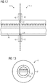
- Figure 13 shows a cross sectional view of a toroidal segment which is filled with a liquid 30 and where the size, in particular the diameter of the assembly flange 42, and the flow obstacle 21 can be well seen. Note that due to the flow obstacle 21 a flow of the liquid 30 is still possible, i.e. a flow through the toroidal segment 41 is still possible; however, the flow is hampered, i.e. obstructed.
Landscapes
- Engineering & Computer Science (AREA)
- Life Sciences & Earth Sciences (AREA)
- Sustainable Development (AREA)
- Sustainable Energy (AREA)
- Chemical & Material Sciences (AREA)
- Combustion & Propulsion (AREA)
- Mechanical Engineering (AREA)
- General Engineering & Computer Science (AREA)
- Vibration Prevention Devices (AREA)
- Wind Motors (AREA)
Description
- The invention relates to a damper of a wind turbine which is suited for damping a movement of the wind turbine.
- Wind turbines usually comprise a tall and slender tower. At the top of the tower the nacelle, which is housing the generator and the rotor, is located. Additionally, the hub with the rotor blades is located at the top of the tower. Thus, the center of mass of the wind turbine is positioned relatively high above the ground. Consequently, the wind turbine is prone to movements, for instance due to wind loads or earthquakes. Wind loads comprise continuous wind flow as well as extreme wind gusts. These movements of the wind turbine are normally undesired as they add structural damages to the wind turbine.
- Thus, the development of a system to damp these undesired movement of the wind turbine is an active field of research. A commonly used design of a damper for a wind turbine tower is a flat circular disc which, for instance, has a hole in the middle. The flat circular disc may have a liquid inside which damps linear motion of the wind turbine tower by providing the liquid sloshing from side to side. The damping of a circular or elliptical movement of the wind turbine tower is provided by a liquid wave moving along the rim of the damper.
- In the state of the art, the flat circular disc is manufactured in one piece and is usually made of plastic.
- Such a liquid damper, however, has several disadvantages. First, it cannot be disassembled easily. As a consequence, transport of the damper from the production site to the installation site as well as the installation of the damper itself is complex and costly. Furthermore, a replacement or a repair of the damper is difficult, if not impossible at all.
- Another disadvantage of a damper which is manufactured in one single piece is that redesigning the damper is complex and costly as it has to be carried out for each new wind turbine type. In other words, an adaption of the design of the damper is costly as no standard elements can be used. As an example, new manufacturing moulds have to be created for each new design of a damper.
- These disadvantages and problems have been solved up to now by, for instance, using several small dampers. Small dampers are easier to transport and to install in the wind turbine. The problem of a difficult replacement and repair of a damper according to the state of the art has been solved up to now by accepting certain leakage of dampers, particularly of large dampers which can hardly be replaced.
- However, these solutions are not satisfying as they actually do not overcome the existing problems and disadvantages.
- Thus, it is an aim of the invention to provide a damper that is easy to integrate in a wind turbine, and, if once incorporated to the wind turbine, is easy to disassemble again, e.g. for repair.
-
- The object of the invention is achieved by the independent claim 1. Further features of the invention are disclosed in the dependent claims.
- In accordance with the invention there is provided a damper of a wind turbine, wherein the damper is suited for damping a movement of the wind turbine. The damper comprises a container and a liquid, wherein the liquid is located inside the container. The damper comprises substantially the shape of a toroid. The container comprises a first toroidal segment and at least a second toroidal segment. Both toroidal segments are attached together such that a closed toroid is generated and the liquid is retained inside the container.
- A key point of the invention is that, by means of the segmented design of the container, transportation, assembling and disassembling, wholly or partly, is significantly facilitated. As a consequence, common factual restrictions regarding the size of the damper are overcome. Additionally, by possibly using standard elements as toroidal segments an adaption to new design requirements is facilitated, too. Finally, a strong and simple geometry of the damper is provided.
- In the context of this application, a wind turbine refers to a device that converts mechanical energy, in particular rotational energy, from the wind into electric energy. A wind turbine may also be denoted as a wind power plant.
- The described damper is well-suited to damp a movement of the wind turbine. This includes a linear movement, which is substantially perpendicular to the tower of the wind turbine. This also includes circular or elliptical movement of the wind turbine. Furthermore, this includes movement in a vertical direction, i.e. in the direction of the tower, as well as any combination of movements. A toroid is informally also denoted as a donut-shaped object. An example of a toroid is an O-ring. A toroid has an annular shape and is generated by revolving a plane geometrical figure about an axis of rotation which is external to that figure and which is parallel to the plane of the figure and which does not intersect the figure. Note that in general this plane geometrical figure can have any shape. As a first example, if that geometrical figure is a rectangle and if that rectangle is rotated about the axis of rotation, then a hollow cylinder is produced. As a second example, if a circle is rotated about the common axis of rotation, then the toroid is also referred to as a torus.
- The container comprises a plurality of toroidal segments which are attached together. If the container only comprises two toroidal segments, namely the first toroidal segment and the second toroidal segment, then both ends of the first toroidal segment are attached to both ends of the second toroidal segment, respectively. If, as another example, the container comprises the first toroidal segment, the second toroidal segment and a third toroidal segment, then the first toroidal segment is attached to the second toroidal segment, the second toroidal segment is attached to the third toroidal segment, and the third toroidal segment is attached to the first toroidal segment, such that at the end a closed toroid is generated by the three attached toroidal segments.
- The notion of a substantially toroidal shape of the damper has to be understood such that small deviations of the shape of the damper with regard to an ideal toroid are also comprised by this description.
- In an advantageous embodiment, the toroid is symmetric about an axis of symmetry. The shape of the toroid is generated by revolving an ellipse, in particular a circle, about the axis of symmetry.
- A toroid with an elliptical, in particular circular cross section benefits from a particularly high structural strength. In other words, a toroid with such a shape can particularly well withstand mechanical forces acting on it. Additionally, such a shape is advantageous if implemented to a circular tower or other element of the wind turbine.
- In contrast to that, a toroid wherein the shape of the toroid is generated by revolving a rectangle is, for instance, advantageous if the damper is placed inside the nacelle of the wind turbine.
- In another advantageous embodiment, the wind turbine comprises a tower, and the damper is located at the tower.
- In order to harvest the most energy out of the wind it is advantageous to place the rotor with the rotor blades elevated from the ground. In other words, it is advantageous if the rotor is placed upon a tower. State of the art wind turbines commonly have a tower with a circular cross section, the cross section being taken in a horizontal plane, i.e. substantially parallel to the ground where the wind turbine is erected.
- In an advantageous embodiment, the damper comprises an aperture at its center which is large enough to give space to an elevator of the tower, wherein the elevator connects the base of the tower with the top of the tower. The damper is located inside the tower.
- In other words, it is advantageous if the container has an aperture around the axis of symmetry with a certain size. It is particularly advantageous if the elevator, which connects the ground and the top of the tower, fits into the aperture. Likewise, if the wind turbine comprises stairs or a ladder instead of an elevator, it is advantageous if the aperture is large enough to give space to the stairs or the ladder, respectively.
- It is further advantageous if the damper is located at the top of the tower or close to the top of the tower. This is advantageous as oscillations of the tower are usually the largest at the top of the tower. Thus, a system for damping is most efficient at the top of the tower.
- In another advantageous embodiment, the damper extends to inner walls of the tower.
- As the tower walls always have a certain thickness, an inner surface of the walls, also denoted as inner walls, as well as an outer surface of the walls, which is also referred to as outer walls, can be assigned to the tower. It may be advantageous to extend the damper as much as possible to the inner walls of the tower. Note that due to the segmented design more design possibilities are feasible and thus large liquid dampers which extend until the inner walls of the tower are also feasible.
- As an example, if the diameter of the inner walls of the tower is 8 meters, the damper may have an outer diameter of 8 meters and an inner diameter of 2 meters. This means that an aperture of 2 meters is present at the center and the remaining space in the tower is filled with the damper, at least within the chosen plane where the damper is placed.
- In another advantageous embodiment, the damper is located outside of the tower.
- This may be advantageous if, for instance, not enough space inside the tower is available. An external damper may also be advantageous if the damper is only installed temporarily. A temporary damper is e.g. advantageous if the damper is only required during installation of the wind turbine. In that case, for example, an external damper might be used during building up the tower and removed as soon as the wind turbine has been entirely assembled and built up.
- In another advantageous embodiment, the wind turbine comprises a nacelle, and the damper is placed at the nacelle.
- The nacelle houses the generator, the rotor and may in addition house or accommodate further devices for the functioning of the wind turbine. It may be beneficial to place the damper within the nacelle.
- In another advantageous embodiment, the liquid is mixed with clay and/or silt.
- In other words, the container comprises the liquid and clay and/or silt. The advantage of having the liquid mixed with the clay and/or the silt is an increase in the mass which may change the damping properties of the damper in an advantageous manner. In particular, this relates to an increase of the mass of the liquid.
- In general, it may be advantageous to have a heavy liquid in the damper.
- In another advantageous embodiment, the liquid comprises a coolant, such as glycol, in order to prevent the liquid from freezing.
- In another advantageous embodiment, the filling level of the liquid inside the container is between 20% and 80%, in particular between 30% and 70%.
- The filling level is defined by the height of the liquid in relation to the total vertical diameter of the container. The filling level is determined during non-movement of the wind turbine. The filling level has a direct impact of the frequency of the damper. In other words, the filling level has a direct impact of the frequency with which the liquid reacts if set in motion by the movement of the wind turbine. A high filling level implicates a high frequency, while a low filling level results in a low frequency. If the filling level is very small, the impact and damping ability of the damper may be small, too. However, if the filling level is too high, the damping impact of the damper may be reduced, too, due to sloshing of the liquid to the vertical or top limitation of the container.
- In another advantageous embodiment, the first toroidal segment and the second toroidal segment are attached together by means of an assembly flange, which is in particular made of steel.
- For instance, the toroidal segments might be made of plastic, while the assembly flange might be a bolted steel assembly flange. In order to ensure a tight and solid connection, gaskets may be introduced between two adjacent parts of the assembly flange. Note that assembly flanges and gaskets are readily available standard objects. This makes the container easy to manufacture and inexpensive. In contrast to the state of the art no individual design and manufacturing is necessary.
- In another advantageous embodiment, the damper comprises at least one flow obstacle inside the container.
- It has been found that flow obstacles, which are also referred to as valves or baffles, might increase the damping capacity of the damper. The flow obstacle might have the shape or design of just a plate that decreases the diameter of the toroidal segment, thus preventing a flow of the liquid from one part of the damper to another part. The flow obstacle may also have the shape and the design of a membrane.
- Advantageously, the flow obstacle is placed at the assembly flange.
- If the container comprises a plurality of assembly flanges, it may be beneficial to add a flow obstacle to each of the assembly flanges.
- In another advantageous embodiment, the container comprises toroidal segments which are shaped as bent toroidal segments. The bent toroidal segments are also referred to as bent pipe sections or turn pipes. Depending on the size of the liquid damper and the size of the industrially available bent toroidal segments, the container may comprise only a few bent toroidal segments or it may comprise a large number of bent toroidal segments.
- In another advantageous embodiment, the container comprises toroidal segments which are shaped as bent toroidal segments and further toroidal segments which are shaped as straight toroidal segments.
- Straight toroidal segments are also referred to as straight pieces of pipe. Note again, that the complete number of used toroidal segments, bent ones as well as straight ones, depend on the design and the size of the damper as well as the availability of industrially available toroidal segments.
- In another advantageous embodiment, the number of bent toroidal segments equals the number of straight toroidal segments. Each bent toroidal segment is directly neighbored by a straight toroidal segment.
- In other words, the toroidal segments are arranged such that each bent toroidal segment is adjacent to a straight toroidal segment and vice versa.
- In another advantageous embodiment, the container comprises a hole for evacuating the liquid from the container.
- An evacuation of the container might be necessary if leakage of the liquid out of the container is noticed. Then, it is advantageous if a possibility of a controlled evacuation of the remaining liquid inside the container is possible. After having evacuated the container one or more toroidal segments may be removed and replaced by new toroidal segments such that the leakage is repaired. Finally a refill of the liquid may be possible by the same hole by which the evacuation has taken place.
-
- Figure 1
- shows a wind turbine with a damper;
- Figure 2
- shows a toroid with a shape of a hollow cylinder;
- Figure 3
- shows a donut-shaped toroid;
- Figure 4
- shows a damper with a hole;
- Figure 5
- shows a damper comprising a first toroidal segment and a second toroidal segment which are attached together;
- Figure 6
- shows a damper with eight toroidal segments;
- Figure 7
- shows a damper with a plurality of straight toroidal segments and a plurality of bent toroidal segments;
- Figure 8
- shows two large liquid dampers installed inside a tower of a wind turbine;
- Figure 9
- shows three double liquid dampers installed inside a tower of a wind turbine;
- Figure 10
- shows a damper which extends to the inner walls of a tower of a wind turbine;
- Figure 11
- shows a damper which is placed at the outer walls of a tower of a wind turbine;
- Figure 12
- shows two toroidal segments which are attached together by means of an assembly flange and with a flow obstacle; and
- Figure 13
- shows a toroidal segment with a flow obstacle in a cross sectional view.
- The illustration in the drawings is in schematic form. It is noted that in different figures, similar or identical elements are provided with the same reference signs.
-
Figure 1 shows awind turbine 10 comprising atower 11 with abase 113 and a top 114. At the top 114 of the tower 10 anacelle 12 is placed. Thenacelle 12 accommodates a generator (not shown) and a rotor (not shown) of thewind turbine 10. At one side of thenacelle 12, ahub 14 is mounted. Thehub 14 is mounted rotatable with regard to thenacelle 12. Thehub 14 is provided with threerotor blades 15, of which two are shown inFigure 1 . Thewind turbine 10 might be a direct drive wind turbine without a gear box or might be a geared wind turbine with a gear box. - The height of the
tower 11 might exceed 70 meters. Thus, it is convenient to incorporate anelevator 13 which connects thebase 113 of thetower 10 with the top 114 of thetower 10. Theelevator 13 is basically used for the service personal which needs to access thenacelle 12, thehub 14 or therotor blades 15. Alternatively, stairs or a ladder may also be installed inside of thetower 11. The space which is needed and occupied by theelevator 13 is referred to asspace 16 for theelevator 13. Close to the top 114 of the tower 11 adamper 20 with a shape of a toroid is located. Thedamper 20 comprises acontainer 40 which is filled with a liquid 30. Thedamper 20 is placed close to thespace 16 for theelevator 13. - An objective of the
damper 20 is to damp or reduce movements of thetower 11. These movements may be linear movements in a plane perpendicular to thetower 11 or circular or elliptical movements. Also vertical movements in a direction in parallel to thetower 11, as they might be induced by an earthquake, might be damped by thedamper 20. The movements may be oscillating movements. Due to the mass of the liquid 30, a force which is acting against the movement of thetower 11 is damping this movement. -
Figures 2 and 3 show two embodiments of a toroid as it might advantageously be used by the present invention. -
Figure 2 shows a toroid that is generated by revolving a rectangle about an axis ofsymmetry 44. The resulting object or body may also be denoted as a hollow cylinder. -
Figure 3 shows a toroid that results from revolving a circle about an axis ofsymmetry 44. The body that is generated by the revolving circle is also denoted as an O-ring or as a donut. - The embodiments shown in
Figure 2 and 3 represent two embodiments of a toroid which are particularly strong and simple at the same time and which thus are well-suited to act as the shape of acontainer 40 of adamper 20. -
Figure 4 shows a cross sectional view of adamper 20 comprising acontainer 40 with a shape of a toroid, in particular a toroid which comprises two circles in a cross sectional view. Thecontainer 40 may be characterized by three basic quantities: adiameter 45, anouter diameter 46, and aheight 47. Note that in the case that thecontainer 40 does not have a circular shape in the cross sectional view as shown inFigure 4 but a random geometrical shape, thediameter 45 might be substituted by an inner diameter. - In the example shown in
Figure 4 , thecontainer 40 is filled with a liquid 30. The fillinglevel 31 is determined by the relative size with regard to theheight 47 of thecontainer 40. In the example ofFigure 4 , the filling level is about 70%. - It is advantageous to incorporate a
hole 43 at thecontainer 40 in order to facilitate evacuation of thecontainer 40 or refill of thecontainer 40. Finally,Figure 4 also shows the axis ofsymmetry 44 of thedamper 20 and thecontainer 40. -
Figures 5 and 6 show two embodiments of acontainer 40 in a top view. -
Figure 5 shows acontainer 40 comprising a firsttoroidal segment 411 and a secondtoroidal segment 412. Bothtoroidal segments toroidal segment 411 and the secondtoroidal segment 412 are attached with each other by means of twoassembly flanges 42. - While the
toroidal segments Figure 5 comprise the shape of a half annulus, thetoroidal segments 41 depicted inFigure 6 comprise the shape of one-eighth of an annulus. All eighttoroidal segments 41 are similar in size and shape. They are linked or attached together byassembly flanges 42. Thus, thecircular container 40 inFigure 6 comprises eighttoroidal segments 41 and eightassembly flanges 42. In addition to the fact that thetoroidal segments 41 are readily available they are also easy to transport to the site of the installation of the wind turbine and are beneficially just assembled together at or during installation of the wind turbine. This is a considerable advantage compared to the state of the art of a damper manufactured in one single piece. -
Figure 7 shows another embodiment of acontainer 40, shown in a top view. In contrast to theFigures 5 and 6 ,Figure 7 shows acontainer 40 which comprises not only benttoroidal segments 413 but also straighttoroidal segments 414. As a result and after connecting the bent and the straighttoroidal segments 413, 414 acontainer 40 with a polygonal shape is obtained. -
Figures 8 and 9 show a part of atower 11 of awind turbine 10. Thetower 11 is delimited by tower walls and comprises aspace 16 which is suited for an elevator or guiding cables from the base of thetower 11 to the top of thetower 11. -
Figure 8 shows twodampers 20 stacked upon each other. -
Figure 9 shows threedampers 20 stacked upon each other, wherein eachdamper 20 comprises two toroidal containers, thus resulting in a double damper. The design and in particular the size of thedamper 20 directly influences the damping characteristics, for instance the damping frequency of the system. -
Figure 10 shows adamper 20 with an elliptical shape shown in a cross sectional view. The size of the damper is chosen such that it extends from thespace 16 suited for the elevator until theinner walls 111 of thetower 11. Such a design allows for a maximum exploitation of the space available inside thetower 11. -
Figure 11 shows an example of anexternal damper 20 that is attached toouter walls 112 of thetower 11. Anexternal damper 20 is advantageous if, for instance, not enough space inside thetower 11 is available or, for instance, if the damper only has to be installed provisionally and is meant to be disassembled shortly after being mounted to thetower 11. -
Figure 12 shows a firsttoroidal segment 411 which is connected with a secondtoroidal segment 412 by means of anassembly flange 42. Note that between the first part of theassembly flange 42 belonging to the firsttoroidal segment 411 and the second part of theassembly flange 42 belonging to the secondtoroidal segment 412, aflow obstacle 21 is incorporated. Theflow obstacle 21 decreases the diameter of the twotoroidal segments flow obstacle 21 is also called a baffle. TheFigure 12 also shows a liquid 30 that is filled into thetoroidal segments - Finally,
Figure 13 shows a cross sectional view of a toroidal segment which is filled with a liquid 30 and where the size, in particular the diameter of theassembly flange 42, and theflow obstacle 21 can be well seen. Note that due to the flow obstacle 21 a flow of the liquid 30 is still possible, i.e. a flow through thetoroidal segment 41 is still possible; however, the flow is hampered, i.e. obstructed.
Claims (17)
- Damper (20) of a wind turbine (10),
wherein- the damper (20) is arranged and prepared for damping a movement of the wind turbine (10),- the damper (20) comprises a container (40) and a liquid (30), the liquid (30) being located inside the container (40),- the damper (20) comprises substantially the shape of a toroid,characterized in that- the container (40) comprises a first toroidal segment (411) and at least a second toroidal segment (412), and- the toroidal segments (41) are attached together such that a closed toroid is generated and the liquid (30) is retained inside the container (40). - Damper (20) according to claim 1,
characterized in that- the toroid is symmetric about an axis of symmetry (44), and- the shape of the toroid, is generated by revolving an ellipse, in particular a circle, about the axis of symmetry (44). - Damper (20) according to one of the preceding claims, characterized in that the liquid (30) is mixed with clay and/or silt.
- Damper (20) according to one of the preceding claims, characterized in that the filling level (31) of the liquid (30) inside the container (40) is between 20% and 80%, in particular between 30% and 70%.
- Damper (20) according to one of the preceding claims,
characterized in that the first toroidal segment (411) and the second toroidal segment (412) are attached together by means of an assembly flange (42), which is in particular made of steel. - Damper (20) according to claim 5,
characterized in that the damper (20) comprises at least one flow obstacle (21) inside the container (40). - Damper (20) according to claim 6,
characterized in that the flow obstacle (21) is placed at the assembly flange (42). - Damper (20) according to one of the preceding claims, characterized in that the container (40) comprises toroidal segments (41) which are shaped as bent toroidal segments (413).
- Damper (20) according to one of the preceding claims, characterized in that the container (40) comprises toroidal segments (41) which are shaped as bent toroidal segments (413), and further toroidal segments (41) which are shaped as straight toroidal segments (414).
- Damper (20) according to claim 9,
characterized in that- the number of bent toroidal segments (413) equals the number of straight toroidal segments (414), and- each bent toroidal segment (413) is directly neighbored by a straight toroidal segment (414). - Damper (20) according to one of the preceding claims,
characterized in that the container (40) comprises a hole (43) for evacuating the liquid (30) from the container (40). - Wind turbine (10) comprising a damper according to one of the claims 1 or 2.
- Wind turbine (10) according to claim 12,
characterized in that- the wind turbine (10) comprises a tower (11), and- the damper (20) is located at the tower (11). - Wind turbine (10) according to one of the claims 12 and 13,
characterized in that- the damper (20) comprises an aperture at its center which is large enough to give space (16) to an elevator (13) of the tower (11) connecting the base of the tower (113) with the top of the tower (114), and- the damper (20) is located inside the tower (11). - Wind turbine (10) according to one of the claims 12 to 14,
characterized in that the damper (20) extends to inner walls (111) of the tower (11). - Wind turbine (10) according to one of the claims 12 to 15,
characterized in that the damper (20) is located outside of the tower (11). - Wind turbine (10) according to one of the claims 12 to 16,
characterized in that- the wind turbine (10) comprises a nacelle (12), and- the damper (20) is placed at the nacelle (12).
Priority Applications (4)
| Application Number | Priority Date | Filing Date | Title |
|---|---|---|---|
| EP14152887.7A EP2899397B1 (en) | 2014-01-28 | 2014-01-28 | Damper of a wind turbine |
| DK14152887.7T DK2899397T3 (en) | 2014-01-28 | 2014-01-28 | Attenuator of a wind turbine |
| US14/560,027 US10161387B2 (en) | 2014-01-28 | 2014-12-04 | Damper of a wind turbine |
| CN201510042608.5A CN104806449B (en) | 2014-01-28 | 2015-01-28 | Damper for a wind turbine |
Applications Claiming Priority (1)
| Application Number | Priority Date | Filing Date | Title |
|---|---|---|---|
| EP14152887.7A EP2899397B1 (en) | 2014-01-28 | 2014-01-28 | Damper of a wind turbine |
Publications (2)
| Publication Number | Publication Date |
|---|---|
| EP2899397A1 EP2899397A1 (en) | 2015-07-29 |
| EP2899397B1 true EP2899397B1 (en) | 2017-01-25 |
Family
ID=50000885
Family Applications (1)
| Application Number | Title | Priority Date | Filing Date |
|---|---|---|---|
| EP14152887.7A Active EP2899397B1 (en) | 2014-01-28 | 2014-01-28 | Damper of a wind turbine |
Country Status (4)
| Country | Link |
|---|---|
| US (1) | US10161387B2 (en) |
| EP (1) | EP2899397B1 (en) |
| CN (1) | CN104806449B (en) |
| DK (1) | DK2899397T3 (en) |
Cited By (2)
| Publication number | Priority date | Publication date | Assignee | Title |
|---|---|---|---|---|
| US11585405B2 (en) | 2019-03-07 | 2023-02-21 | Siemens Gamesa Renewable Energy A/S | Assembly of a tower section of a wind turbine tower |
| US12253060B2 (en) | 2022-06-15 | 2025-03-18 | Siemens Gamesa Renewable Energy A/S | Liquid damper |
Families Citing this family (22)
| Publication number | Priority date | Publication date | Assignee | Title |
|---|---|---|---|---|
| CN105308315B (en) * | 2013-06-11 | 2018-09-11 | 维斯塔斯风力系统有限公司 | Wind turbine tower with damper |
| EP2884095B1 (en) * | 2013-12-12 | 2016-08-24 | Siemens Aktiengesellschaft | Tuned liquid damper of a wind turbine |
| US10655605B2 (en) * | 2015-09-09 | 2020-05-19 | Noel Richard Potter | Balancing a wind turbine |
| US20170067442A1 (en) * | 2015-09-09 | 2017-03-09 | Noel R. Potter | Apparatuses and methods for balancing a wind turbine assembly |
| WO2018059638A1 (en) * | 2016-09-27 | 2018-04-05 | Vestas Wind Systems A/S | Tower vibration damper |
| CN106567803A (en) * | 2016-10-28 | 2017-04-19 | 同济大学 | Round pipe liquid damper used for weakening edge vibration of wind turbine blades |
| US20200378466A1 (en) * | 2017-02-21 | 2020-12-03 | Vestas Wind Systems A/S | Tower vibration damper |
| ES2856923T3 (en) | 2017-11-02 | 2021-09-28 | Soletanche Freyssinet | Device for damping vibrations in a structure and use of the device |
| DK3514374T3 (en) * | 2018-01-17 | 2021-09-27 | Siemens Gamesa Renewable Energy As | Windmill |
| CN110630076B (en) * | 2018-06-28 | 2020-11-24 | 北京金风科创风电设备有限公司 | Damper and load-bearing enclosure having the same |
| CN116857120A (en) | 2018-06-29 | 2023-10-10 | 维斯塔斯风力系统有限公司 | Method of erecting a wind turbine |
| US11754050B2 (en) | 2018-12-20 | 2023-09-12 | Vestas Wind Systems A/S | Modular tower damper system |
| ES2902989T3 (en) * | 2019-01-02 | 2022-03-30 | Siemens Gamesa Renewable Energy As | System, set of tests and method for fatigue tests of a wind turbine blade |
| EP3966450B1 (en) * | 2019-05-06 | 2024-04-03 | Vestas Wind Systems A/S | Vibration damping of a structure |
| ES2825223A1 (en) * | 2019-11-14 | 2021-05-14 | Siemens Gamesa Renewable Energy As | Formulation to increase the density of liquids for industrial uses (Machine-translation by Google Translate, not legally binding) |
| JP7392142B2 (en) * | 2019-11-14 | 2023-12-05 | シーメンス ガメサ リニューアブル エナジー エー/エス | damper for wind turbines |
| CN111173683A (en) * | 2020-01-03 | 2020-05-19 | 国电联合动力技术有限公司 | Flexible tower wind damper control device and method for wind turbine generator and wind turbine generator |
| CN112962809A (en) * | 2021-02-22 | 2021-06-15 | 三一重能股份有限公司 | Liquid damper, liquid damper system and vibration damping method |
| CN113738587A (en) * | 2021-09-23 | 2021-12-03 | 国电联合动力技术有限公司 | Tower barrel assembly and wind generating set |
| CN114809765B (en) * | 2022-04-18 | 2023-01-31 | 清华大学 | Tuned liquid column damper and tower with adjustable liquid level |
| DK4293220T3 (en) * | 2022-06-15 | 2025-04-07 | Siemens Gamesa Renewable Energy As | Leak containment arrangement |
| CN116292127B (en) * | 2023-04-26 | 2024-11-12 | 中国长江三峡集团有限公司 | An adaptive tuning vibration reduction system for offshore wind power generation system |
Family Cites Families (10)
| Publication number | Priority date | Publication date | Assignee | Title |
|---|---|---|---|---|
| SU992683A1 (en) * | 1980-02-29 | 1983-01-30 | Проектно-технологический трест "Оргтехстрой" | Oscillation damper for high-rise structures |
| NL8603259A (en) * | 1986-12-22 | 1988-07-18 | Lenten Hendrik | LIQUID BUFFER TO PROTECT BUILDINGS FROM EARTHQUAKES. |
| US4953330A (en) * | 1987-12-01 | 1990-09-04 | Mitsui Kensetsu Kabushiki Kaisha | Damping device in a structure and damping construction and damping method using those devices |
| EP0686733B2 (en) * | 1994-05-31 | 2003-02-26 | Multicon Schwingungsdämpfer und Planung GmbH | Vibration absorber for vibration-endangered structural parts and structures |
| US7220104B2 (en) * | 2004-12-30 | 2007-05-22 | General Electric Company | Vibration reduction system for a wind turbine |
| EP1855000A1 (en) * | 2006-05-12 | 2007-11-14 | Siemens Aktiengesellschaft | Liquid sloshing damper |
| BRPI0817375A2 (en) * | 2007-11-28 | 2015-03-31 | Vestas Wind Sys As | "method for damping wind turbine oscillations" |
| US20090148289A1 (en) | 2007-12-06 | 2009-06-11 | Thomas Edenfeld | Active damper against generator base frame vibrations |
| EP2434154A1 (en) | 2010-09-28 | 2012-03-28 | Siemens Aktiengesellschaft | Wind turbine active damping arrangement |
| US8123484B2 (en) * | 2011-02-04 | 2012-02-28 | Vestas Wind Systems A/S | Torsional dynamic damper for a wind turbine and method of using same |
-
2014
- 2014-01-28 DK DK14152887.7T patent/DK2899397T3/en active
- 2014-01-28 EP EP14152887.7A patent/EP2899397B1/en active Active
- 2014-12-04 US US14/560,027 patent/US10161387B2/en active Active
-
2015
- 2015-01-28 CN CN201510042608.5A patent/CN104806449B/en active Active
Non-Patent Citations (1)
| Title |
|---|
| None * |
Cited By (2)
| Publication number | Priority date | Publication date | Assignee | Title |
|---|---|---|---|---|
| US11585405B2 (en) | 2019-03-07 | 2023-02-21 | Siemens Gamesa Renewable Energy A/S | Assembly of a tower section of a wind turbine tower |
| US12253060B2 (en) | 2022-06-15 | 2025-03-18 | Siemens Gamesa Renewable Energy A/S | Liquid damper |
Also Published As
| Publication number | Publication date |
|---|---|
| CN104806449B (en) | 2021-04-30 |
| CN104806449A (en) | 2015-07-29 |
| EP2899397A1 (en) | 2015-07-29 |
| US10161387B2 (en) | 2018-12-25 |
| DK2899397T3 (en) | 2017-04-10 |
| US20150211496A1 (en) | 2015-07-30 |
Similar Documents
| Publication | Publication Date | Title |
|---|---|---|
| EP2899397B1 (en) | Damper of a wind turbine | |
| EP2570555B1 (en) | A tower base section of a wind turbine, a wind turbine and a system for mounting a tower | |
| US20130180199A1 (en) | Flange connection for a wind turbine and method of connecting parts of a wind turbine | |
| EP2952655B1 (en) | Lattice tower | |
| EP2481927B1 (en) | Modular tower and methods of assembling same | |
| CA2524931C (en) | Foundation for a wind energy plant | |
| US8186966B2 (en) | Offshore wind turbine generator | |
| EP2375057B1 (en) | Wind turbine installation | |
| EP2837820B1 (en) | Segmented wind turbine hub | |
| CN102374114B (en) | For the wheel hub of wind turbine and the method for mounting wind | |
| US20140069046A1 (en) | Wind turbine tower base assembly with detachable tower base rings | |
| US20120131876A1 (en) | Hoisting nacelle and tower | |
| US9644386B2 (en) | Connection between lattice tower and nacelle | |
| EP2372144B1 (en) | Wind turbine, tower and method for fabricating the same | |
| WO2009126696A1 (en) | Wind-driven generation of power | |
| US20090317256A1 (en) | Rotor hub of a wind energy plant | |
| JP2010285992A (en) | Wind turbine tower that can be transported by rail | |
| KR20110134933A (en) | In-house hydraulic system and turbine | |
| KR101318111B1 (en) | Substructure of hybrid offshore wind turbine with multi-pile for reducing wave forces, and constructing method for the same | |
| EP2574772B1 (en) | Wind turbine tower | |
| CN102052263A (en) | Transportable wind turbine tower | |
| CN105822509A (en) | Vibration damper for a wind turbine, method for installing a vibration damper in a tower of a wind energy system and wind energy system | |
| US12297886B2 (en) | Oscillation damping | |
| US20150167643A1 (en) | Tuned liquid damper of a wind turbine | |
| US20160265514A1 (en) | Support device and methods for improving and constructing a support device |
Legal Events
| Date | Code | Title | Description |
|---|---|---|---|
| PUAI | Public reference made under article 153(3) epc to a published international application that has entered the european phase |
Free format text: ORIGINAL CODE: 0009012 |
|
| 17P | Request for examination filed |
Effective date: 20141106 |
|
| AK | Designated contracting states |
Kind code of ref document: A1 Designated state(s): AL AT BE BG CH CY CZ DE DK EE ES FI FR GB GR HR HU IE IS IT LI LT LU LV MC MK MT NL NO PL PT RO RS SE SI SK SM TR |
|
| AX | Request for extension of the european patent |
Extension state: BA ME |
|
| REG | Reference to a national code |
Ref country code: DE Ref legal event code: R079 Ref document number: 602014006288 Country of ref document: DE Free format text: PREVIOUS MAIN CLASS: F03D0011000000 Ipc: F03D0080000000 |
|
| RIC1 | Information provided on ipc code assigned before grant |
Ipc: F03D 80/00 20160101AFI20160630BHEP Ipc: F03D 13/20 20160101ALI20160630BHEP Ipc: E04B 1/98 20060101ALI20160630BHEP |
|
| GRAP | Despatch of communication of intention to grant a patent |
Free format text: ORIGINAL CODE: EPIDOSNIGR1 |
|
| INTG | Intention to grant announced |
Effective date: 20160810 |
|
| GRAS | Grant fee paid |
Free format text: ORIGINAL CODE: EPIDOSNIGR3 |
|
| GRAA | (expected) grant |
Free format text: ORIGINAL CODE: 0009210 |
|
| AK | Designated contracting states |
Kind code of ref document: B1 Designated state(s): AL AT BE BG CH CY CZ DE DK EE ES FI FR GB GR HR HU IE IS IT LI LT LU LV MC MK MT NL NO PL PT RO RS SE SI SK SM TR |
|
| REG | Reference to a national code |
Ref country code: GB Ref legal event code: FG4D |
|
| REG | Reference to a national code |
Ref country code: CH Ref legal event code: EP |
|
| REG | Reference to a national code |
Ref country code: AT Ref legal event code: REF Ref document number: 864317 Country of ref document: AT Kind code of ref document: T Effective date: 20170215 |
|
| REG | Reference to a national code |
Ref country code: IE Ref legal event code: FG4D Ref country code: FR Ref legal event code: PLFP Year of fee payment: 4 |
|
| REG | Reference to a national code |
Ref country code: DE Ref legal event code: R096 Ref document number: 602014006288 Country of ref document: DE |
|
| REG | Reference to a national code |
Ref country code: DK Ref legal event code: T3 Effective date: 20170404 |
|
| REG | Reference to a national code |
Ref country code: LT Ref legal event code: MG4D |
|
| PG25 | Lapsed in a contracting state [announced via postgrant information from national office to epo] |
Ref country code: BE Free format text: LAPSE BECAUSE OF NON-PAYMENT OF DUE FEES Effective date: 20170131 |
|
| REG | Reference to a national code |
Ref country code: NL Ref legal event code: MP Effective date: 20170125 |
|
| REG | Reference to a national code |
Ref country code: AT Ref legal event code: MK05 Ref document number: 864317 Country of ref document: AT Kind code of ref document: T Effective date: 20170125 |
|
| PG25 | Lapsed in a contracting state [announced via postgrant information from national office to epo] |
Ref country code: NL Free format text: LAPSE BECAUSE OF FAILURE TO SUBMIT A TRANSLATION OF THE DESCRIPTION OR TO PAY THE FEE WITHIN THE PRESCRIBED TIME-LIMIT Effective date: 20170125 |
|
| PG25 | Lapsed in a contracting state [announced via postgrant information from national office to epo] |
Ref country code: IS Free format text: LAPSE BECAUSE OF FAILURE TO SUBMIT A TRANSLATION OF THE DESCRIPTION OR TO PAY THE FEE WITHIN THE PRESCRIBED TIME-LIMIT Effective date: 20170525 Ref country code: LT Free format text: LAPSE BECAUSE OF FAILURE TO SUBMIT A TRANSLATION OF THE DESCRIPTION OR TO PAY THE FEE WITHIN THE PRESCRIBED TIME-LIMIT Effective date: 20170125 Ref country code: FI Free format text: LAPSE BECAUSE OF FAILURE TO SUBMIT A TRANSLATION OF THE DESCRIPTION OR TO PAY THE FEE WITHIN THE PRESCRIBED TIME-LIMIT Effective date: 20170125 Ref country code: HR Free format text: LAPSE BECAUSE OF FAILURE TO SUBMIT A TRANSLATION OF THE DESCRIPTION OR TO PAY THE FEE WITHIN THE PRESCRIBED TIME-LIMIT Effective date: 20170125 Ref country code: NO Free format text: LAPSE BECAUSE OF FAILURE TO SUBMIT A TRANSLATION OF THE DESCRIPTION OR TO PAY THE FEE WITHIN THE PRESCRIBED TIME-LIMIT Effective date: 20170425 Ref country code: GR Free format text: LAPSE BECAUSE OF FAILURE TO SUBMIT A TRANSLATION OF THE DESCRIPTION OR TO PAY THE FEE WITHIN THE PRESCRIBED TIME-LIMIT Effective date: 20170426 |
|
| RAP2 | Party data changed (patent owner data changed or rights of a patent transferred) |
Owner name: SIEMENS AKTIENGESELLSCHAFT |
|
| PG25 | Lapsed in a contracting state [announced via postgrant information from national office to epo] |
Ref country code: SE Free format text: LAPSE BECAUSE OF FAILURE TO SUBMIT A TRANSLATION OF THE DESCRIPTION OR TO PAY THE FEE WITHIN THE PRESCRIBED TIME-LIMIT Effective date: 20170125 Ref country code: PT Free format text: LAPSE BECAUSE OF FAILURE TO SUBMIT A TRANSLATION OF THE DESCRIPTION OR TO PAY THE FEE WITHIN THE PRESCRIBED TIME-LIMIT Effective date: 20170525 Ref country code: ES Free format text: LAPSE BECAUSE OF FAILURE TO SUBMIT A TRANSLATION OF THE DESCRIPTION OR TO PAY THE FEE WITHIN THE PRESCRIBED TIME-LIMIT Effective date: 20170125 Ref country code: PL Free format text: LAPSE BECAUSE OF FAILURE TO SUBMIT A TRANSLATION OF THE DESCRIPTION OR TO PAY THE FEE WITHIN THE PRESCRIBED TIME-LIMIT Effective date: 20170125 Ref country code: BG Free format text: LAPSE BECAUSE OF FAILURE TO SUBMIT A TRANSLATION OF THE DESCRIPTION OR TO PAY THE FEE WITHIN THE PRESCRIBED TIME-LIMIT Effective date: 20170425 Ref country code: AT Free format text: LAPSE BECAUSE OF FAILURE TO SUBMIT A TRANSLATION OF THE DESCRIPTION OR TO PAY THE FEE WITHIN THE PRESCRIBED TIME-LIMIT Effective date: 20170125 Ref country code: LV Free format text: LAPSE BECAUSE OF FAILURE TO SUBMIT A TRANSLATION OF THE DESCRIPTION OR TO PAY THE FEE WITHIN THE PRESCRIBED TIME-LIMIT Effective date: 20170125 Ref country code: RS Free format text: LAPSE BECAUSE OF FAILURE TO SUBMIT A TRANSLATION OF THE DESCRIPTION OR TO PAY THE FEE WITHIN THE PRESCRIBED TIME-LIMIT Effective date: 20170125 |
|
| REG | Reference to a national code |
Ref country code: CH Ref legal event code: PL |
|
| REG | Reference to a national code |
Ref country code: DE Ref legal event code: R097 Ref document number: 602014006288 Country of ref document: DE |
|
| PG25 | Lapsed in a contracting state [announced via postgrant information from national office to epo] |
Ref country code: IT Free format text: LAPSE BECAUSE OF FAILURE TO SUBMIT A TRANSLATION OF THE DESCRIPTION OR TO PAY THE FEE WITHIN THE PRESCRIBED TIME-LIMIT Effective date: 20170125 Ref country code: SK Free format text: LAPSE BECAUSE OF FAILURE TO SUBMIT A TRANSLATION OF THE DESCRIPTION OR TO PAY THE FEE WITHIN THE PRESCRIBED TIME-LIMIT Effective date: 20170125 Ref country code: LI Free format text: LAPSE BECAUSE OF NON-PAYMENT OF DUE FEES Effective date: 20170131 Ref country code: RO Free format text: LAPSE BECAUSE OF FAILURE TO SUBMIT A TRANSLATION OF THE DESCRIPTION OR TO PAY THE FEE WITHIN THE PRESCRIBED TIME-LIMIT Effective date: 20170125 Ref country code: CZ Free format text: LAPSE BECAUSE OF FAILURE TO SUBMIT A TRANSLATION OF THE DESCRIPTION OR TO PAY THE FEE WITHIN THE PRESCRIBED TIME-LIMIT Effective date: 20170125 Ref country code: EE Free format text: LAPSE BECAUSE OF FAILURE TO SUBMIT A TRANSLATION OF THE DESCRIPTION OR TO PAY THE FEE WITHIN THE PRESCRIBED TIME-LIMIT Effective date: 20170125 Ref country code: CH Free format text: LAPSE BECAUSE OF NON-PAYMENT OF DUE FEES Effective date: 20170131 |
|
| REG | Reference to a national code |
Ref country code: IE Ref legal event code: MM4A |
|
| PG25 | Lapsed in a contracting state [announced via postgrant information from national office to epo] |
Ref country code: LU Free format text: LAPSE BECAUSE OF NON-PAYMENT OF DUE FEES Effective date: 20170128 Ref country code: MC Free format text: LAPSE BECAUSE OF FAILURE TO SUBMIT A TRANSLATION OF THE DESCRIPTION OR TO PAY THE FEE WITHIN THE PRESCRIBED TIME-LIMIT Effective date: 20170125 Ref country code: SM Free format text: LAPSE BECAUSE OF FAILURE TO SUBMIT A TRANSLATION OF THE DESCRIPTION OR TO PAY THE FEE WITHIN THE PRESCRIBED TIME-LIMIT Effective date: 20170125 |
|
| PLBE | No opposition filed within time limit |
Free format text: ORIGINAL CODE: 0009261 |
|
| STAA | Information on the status of an ep patent application or granted ep patent |
Free format text: STATUS: NO OPPOSITION FILED WITHIN TIME LIMIT |
|
| 26N | No opposition filed |
Effective date: 20171026 |
|
| REG | Reference to a national code |
Ref country code: FR Ref legal event code: PLFP Year of fee payment: 5 |
|
| REG | Reference to a national code |
Ref country code: BE Ref legal event code: MM Effective date: 20170131 |
|
| PG25 | Lapsed in a contracting state [announced via postgrant information from national office to epo] |
Ref country code: SI Free format text: LAPSE BECAUSE OF FAILURE TO SUBMIT A TRANSLATION OF THE DESCRIPTION OR TO PAY THE FEE WITHIN THE PRESCRIBED TIME-LIMIT Effective date: 20170125 Ref country code: IE Free format text: LAPSE BECAUSE OF NON-PAYMENT OF DUE FEES Effective date: 20170128 |
|
| PG25 | Lapsed in a contracting state [announced via postgrant information from national office to epo] |
Ref country code: MT Free format text: LAPSE BECAUSE OF NON-PAYMENT OF DUE FEES Effective date: 20170128 |
|
| PG25 | Lapsed in a contracting state [announced via postgrant information from national office to epo] |
Ref country code: HU Free format text: LAPSE BECAUSE OF FAILURE TO SUBMIT A TRANSLATION OF THE DESCRIPTION OR TO PAY THE FEE WITHIN THE PRESCRIBED TIME-LIMIT; INVALID AB INITIO Effective date: 20140128 |
|
| REG | Reference to a national code |
Ref country code: DE Ref legal event code: R081 Ref document number: 602014006288 Country of ref document: DE Owner name: SIEMENS GAMESA RENEWABLE ENERGY A/S, DK Free format text: FORMER OWNER: SIEMENS AKTIENGESELLSCHAFT, 80333 MUENCHEN, DE |
|
| PG25 | Lapsed in a contracting state [announced via postgrant information from national office to epo] |
Ref country code: CY Free format text: LAPSE BECAUSE OF FAILURE TO SUBMIT A TRANSLATION OF THE DESCRIPTION OR TO PAY THE FEE WITHIN THE PRESCRIBED TIME-LIMIT Effective date: 20170125 |
|
| PG25 | Lapsed in a contracting state [announced via postgrant information from national office to epo] |
Ref country code: MK Free format text: LAPSE BECAUSE OF FAILURE TO SUBMIT A TRANSLATION OF THE DESCRIPTION OR TO PAY THE FEE WITHIN THE PRESCRIBED TIME-LIMIT Effective date: 20170125 |
|
| REG | Reference to a national code |
Ref country code: GB Ref legal event code: 732E Free format text: REGISTERED BETWEEN 20191128 AND 20191204 |
|
| PG25 | Lapsed in a contracting state [announced via postgrant information from national office to epo] |
Ref country code: TR Free format text: LAPSE BECAUSE OF FAILURE TO SUBMIT A TRANSLATION OF THE DESCRIPTION OR TO PAY THE FEE WITHIN THE PRESCRIBED TIME-LIMIT Effective date: 20170125 |
|
| PG25 | Lapsed in a contracting state [announced via postgrant information from national office to epo] |
Ref country code: AL Free format text: LAPSE BECAUSE OF FAILURE TO SUBMIT A TRANSLATION OF THE DESCRIPTION OR TO PAY THE FEE WITHIN THE PRESCRIBED TIME-LIMIT Effective date: 20170125 |
|
| PGFP | Annual fee paid to national office [announced via postgrant information from national office to epo] |
Ref country code: DE Payment date: 20250129 Year of fee payment: 12 |
|
| PGFP | Annual fee paid to national office [announced via postgrant information from national office to epo] |
Ref country code: DK Payment date: 20250127 Year of fee payment: 12 |
|
| PGFP | Annual fee paid to national office [announced via postgrant information from national office to epo] |
Ref country code: FR Payment date: 20250127 Year of fee payment: 12 |
|
| PGFP | Annual fee paid to national office [announced via postgrant information from national office to epo] |
Ref country code: GB Payment date: 20250121 Year of fee payment: 12 |