US10655605B2 - Balancing a wind turbine - Google Patents
Balancing a wind turbine Download PDFInfo
- Publication number
- US10655605B2 US10655605B2 US16/130,329 US201816130329A US10655605B2 US 10655605 B2 US10655605 B2 US 10655605B2 US 201816130329 A US201816130329 A US 201816130329A US 10655605 B2 US10655605 B2 US 10655605B2
- Authority
- US
- United States
- Prior art keywords
- shaft
- wind turbine
- turbine
- support structure
- balancing
- Prior art date
- Legal status (The legal status is an assumption and is not a legal conclusion. Google has not performed a legal analysis and makes no representation as to the accuracy of the status listed.)
- Expired - Fee Related
Links
- 238000000034 method Methods 0.000 claims abstract description 28
- 239000011324 bead Substances 0.000 claims description 8
- 230000008878 coupling Effects 0.000 claims description 2
- 238000010168 coupling process Methods 0.000 claims description 2
- 238000005859 coupling reaction Methods 0.000 claims description 2
- 238000010586 diagram Methods 0.000 description 14
- 238000009987 spinning Methods 0.000 description 6
- 238000012986 modification Methods 0.000 description 4
- 230000004048 modification Effects 0.000 description 4
- 230000010355 oscillation Effects 0.000 description 4
- 230000008901 benefit Effects 0.000 description 3
- 239000002245 particle Substances 0.000 description 3
- 238000013016 damping Methods 0.000 description 2
- 230000002093 peripheral effect Effects 0.000 description 2
- 239000004033 plastic Substances 0.000 description 2
- 239000004576 sand Substances 0.000 description 2
- 235000017166 Bambusa arundinacea Nutrition 0.000 description 1
- 235000017491 Bambusa tulda Nutrition 0.000 description 1
- 241001330002 Bambuseae Species 0.000 description 1
- 229920000049 Carbon (fiber) Polymers 0.000 description 1
- 235000015334 Phyllostachys viridis Nutrition 0.000 description 1
- 230000002411 adverse Effects 0.000 description 1
- 239000011425 bamboo Substances 0.000 description 1
- 239000004917 carbon fiber Substances 0.000 description 1
- 230000006378 damage Effects 0.000 description 1
- 230000000694 effects Effects 0.000 description 1
- 239000011152 fibreglass Substances 0.000 description 1
- 229910052500 inorganic mineral Inorganic materials 0.000 description 1
- 239000002184 metal Substances 0.000 description 1
- VNWKTOKETHGBQD-UHFFFAOYSA-N methane Chemical compound C VNWKTOKETHGBQD-UHFFFAOYSA-N 0.000 description 1
- 239000011707 mineral Substances 0.000 description 1
- 239000011435 rock Substances 0.000 description 1
- 230000002459 sustained effect Effects 0.000 description 1
Images


Classifications
-
- F—MECHANICAL ENGINEERING; LIGHTING; HEATING; WEAPONS; BLASTING
- F03—MACHINES OR ENGINES FOR LIQUIDS; WIND, SPRING, OR WEIGHT MOTORS; PRODUCING MECHANICAL POWER OR A REACTIVE PROPULSIVE THRUST, NOT OTHERWISE PROVIDED FOR
- F03D—WIND MOTORS
- F03D13/00—Assembly, mounting or commissioning of wind motors; Arrangements specially adapted for transporting wind motor components
- F03D13/30—Commissioning, e.g. inspection, testing or final adjustment before releasing for production
- F03D13/35—Balancing static or dynamic imbalances
-
- F—MECHANICAL ENGINEERING; LIGHTING; HEATING; WEAPONS; BLASTING
- F03—MACHINES OR ENGINES FOR LIQUIDS; WIND, SPRING, OR WEIGHT MOTORS; PRODUCING MECHANICAL POWER OR A REACTIVE PROPULSIVE THRUST, NOT OTHERWISE PROVIDED FOR
- F03D—WIND MOTORS
- F03D3/00—Wind motors with rotation axis substantially perpendicular to the air flow entering the rotor
- F03D3/005—Wind motors with rotation axis substantially perpendicular to the air flow entering the rotor the axis being vertical
-
- F—MECHANICAL ENGINEERING; LIGHTING; HEATING; WEAPONS; BLASTING
- F03—MACHINES OR ENGINES FOR LIQUIDS; WIND, SPRING, OR WEIGHT MOTORS; PRODUCING MECHANICAL POWER OR A REACTIVE PROPULSIVE THRUST, NOT OTHERWISE PROVIDED FOR
- F03D—WIND MOTORS
- F03D3/00—Wind motors with rotation axis substantially perpendicular to the air flow entering the rotor
- F03D3/06—Rotors
- F03D3/062—Rotors characterised by their construction elements
-
- F—MECHANICAL ENGINEERING; LIGHTING; HEATING; WEAPONS; BLASTING
- F03—MACHINES OR ENGINES FOR LIQUIDS; WIND, SPRING, OR WEIGHT MOTORS; PRODUCING MECHANICAL POWER OR A REACTIVE PROPULSIVE THRUST, NOT OTHERWISE PROVIDED FOR
- F03D—WIND MOTORS
- F03D7/00—Controlling wind motors
- F03D7/06—Controlling wind motors the wind motors having rotation axis substantially perpendicular to the air flow entering the rotor
-
- F—MECHANICAL ENGINEERING; LIGHTING; HEATING; WEAPONS; BLASTING
- F05—INDEXING SCHEMES RELATING TO ENGINES OR PUMPS IN VARIOUS SUBCLASSES OF CLASSES F01-F04
- F05B—INDEXING SCHEME RELATING TO WIND, SPRING, WEIGHT, INERTIA OR LIKE MOTORS, TO MACHINES OR ENGINES FOR LIQUIDS COVERED BY SUBCLASSES F03B, F03D AND F03G
- F05B2240/00—Components
- F05B2240/20—Rotors
- F05B2240/21—Rotors for wind turbines
- F05B2240/211—Rotors for wind turbines with vertical axis
-
- F—MECHANICAL ENGINEERING; LIGHTING; HEATING; WEAPONS; BLASTING
- F05—INDEXING SCHEMES RELATING TO ENGINES OR PUMPS IN VARIOUS SUBCLASSES OF CLASSES F01-F04
- F05B—INDEXING SCHEME RELATING TO WIND, SPRING, WEIGHT, INERTIA OR LIKE MOTORS, TO MACHINES OR ENGINES FOR LIQUIDS COVERED BY SUBCLASSES F03B, F03D AND F03G
- F05B2260/00—Function
- F05B2260/96—Preventing, counteracting or reducing vibration or noise
- F05B2260/964—Preventing, counteracting or reducing vibration or noise by damping means
-
- F—MECHANICAL ENGINEERING; LIGHTING; HEATING; WEAPONS; BLASTING
- F05—INDEXING SCHEMES RELATING TO ENGINES OR PUMPS IN VARIOUS SUBCLASSES OF CLASSES F01-F04
- F05B—INDEXING SCHEME RELATING TO WIND, SPRING, WEIGHT, INERTIA OR LIKE MOTORS, TO MACHINES OR ENGINES FOR LIQUIDS COVERED BY SUBCLASSES F03B, F03D AND F03G
- F05B2260/00—Function
- F05B2260/96—Preventing, counteracting or reducing vibration or noise
- F05B2260/966—Preventing, counteracting or reducing vibration or noise by correcting static or dynamic imbalance
-
- Y—GENERAL TAGGING OF NEW TECHNOLOGICAL DEVELOPMENTS; GENERAL TAGGING OF CROSS-SECTIONAL TECHNOLOGIES SPANNING OVER SEVERAL SECTIONS OF THE IPC; TECHNICAL SUBJECTS COVERED BY FORMER USPC CROSS-REFERENCE ART COLLECTIONS [XRACs] AND DIGESTS
- Y02—TECHNOLOGIES OR APPLICATIONS FOR MITIGATION OR ADAPTATION AGAINST CLIMATE CHANGE
- Y02E—REDUCTION OF GREENHOUSE GAS [GHG] EMISSIONS, RELATED TO ENERGY GENERATION, TRANSMISSION OR DISTRIBUTION
- Y02E10/00—Energy generation through renewable energy sources
- Y02E10/70—Wind energy
- Y02E10/74—Wind turbines with rotation axis perpendicular to the wind direction
Definitions
- the present disclosure relates generally to a wind turbine balancing channel (e.g., enclosed balancing channel) or balancing tube, and more particularly, to techniques for balancing a wind turbine device.
- a wind turbine balancing channel e.g., enclosed balancing channel
- balancing tube e.g., balancing tube
- a wind turbine may transmit mechanical power generated by the wind turbine into electrical power. Wind incident on an airfoil may cause the wind turbine to spin. The mechanical power of the turbine shaft spinning may be converted into electrical power.
- the force of the wind may cause the wind turbine to spin at relatively high speeds.
- the wind turbine may experience adverse effects from an imbalance within the wind turbine that may result in structural vibrations, resonance, speed wobbles, oscillations, vortex shedding, dynamic aero-elasticity, etc.
- a sustained and/or increasing amplitude of oscillation among the pieces of the wind turbine may result in destruction of the wind turbine.
- benefits may be realized by techniques for balancing a wind turbine.
- wind turbine may include a balancing system configured to balance the wind turbine.
- a turbine shaft may be configured to transmit mechanical power.
- the turbine shaft may transmit mechanical power to an electrical generator and/or alternator.
- the wind turbine may include a support structure.
- a portion of the support structure may couple to the turbine shaft.
- a portion of the support structure may couple to a vane shaft of the wind turbine.
- the wind turbine may include one or more vane shafts.
- a balancing channel e.g., enclosed balancing channel
- balancing tube may be coupled to the vane shaft.
- the balancing channel may include a hollow chamber. In one example, multiple freely moving objects may be placed within the hollow chamber of the balancing channel.
- the freely moving objects may include at least one spherical bead.
- a diameter of the at least one spherical bead may be less than half an inner diameter of the balancing channel, or less than half an inner diameter of the hollow chamber of the balancing channel.
- At least a portion of a cross section of the balancing channel may include a circular shape, an oval shape, a rectangular shape, or a square shape, or any combination thereof.
- the shape of the cross section of the balancing channel may be any mechanically feasible polygon.
- the support structure may include one or more support arms. In some cases, at least one of the one or more support arms may extend from the vane shaft to the balancing channel. In some cases, at least one of the one or more support arms extends from the vane shaft to the turbine shaft. In one example, the vane shaft may be coupled to at least one of the one or more support arms.
- the vane shaft may be configured to rotate about an axis running vertically down a center of the vane shaft.
- the vane shaft may be connected to an airfoil.
- the airfoil may be configured to rotate freely about the vertical axis of the vane shaft.
- the wind turbine may include one or more airfoils, where each airfoil connects to its own vane shaft.
- the support structure may include an upper support structure attached to a top of the vane shaft above the airfoil. In some cases, the balancing channel may be attached to the upper support structure. In one example, the support structure may include a lower support structure attached to a bottom of the vane shaft below the airfoil. In one example, the balancing channel may be attached to the lower support structure. In some cases, the wind turbine may include at least two balancing channels. For example, the wind turbine may include at least a first or upper balancing channel placed above the airfoil and a second or lower balancing channel placed below the airfoil.
- a radius from the turbine shaft to an edge of the balancing channel is below or equal to a radius from the turbine shaft to the vane shaft. In some cases, a radius from the turbine shaft to an edge of the balancing channel is greater than a radius from the turbine shaft to the vane shaft. In some cases, at least a portion of the support structure extends beyond an outer edge of the balancing channel.
- a turbine shaft may be configured to transmit mechanical power.
- a support structure may be coupled to the turbine shaft.
- the support structure may include one or more support arms.
- a balancing channel (e.g., enclosed balancing channel) or balancing tube may be coupled to at least a portion of the support structure.
- the balancing channel may include a hollow chamber. Multiple freely moving objects may be placed within the hollow chamber of the balancing channel.
- At least one of the freely moving objects may include a spherical object.
- at least a portion of the balancing channel may connect to the support structure toward a top portion of the wind turbine. Additionally, or alternatively, at least a portion of the balancing channel may connect to the support structure toward a bottom portion of the wind turbine.
- at least a portion of a cross section of the balancing channel comprises a circular portion, an oval portion, a rectangular portion, a triangular portion, a hexagonal portion, an octagonal portion, a square portion, etc.
- at least a portion of a cross section of the balancing channel comprises a top portion, a bottom portion, an inner wall portion toward the turbine shaft, and an outer wall portion toward the peripheral portion of the support structure.
- the support structure may include one or more support arms radiating outward away from the turbine shaft.
- the balancing channel may connect to at least one of the one or more of the support arms.
- the wind turbine may include a vane shaft connected to at least one of the one or more support arms.
- the vane shaft may support one or more airfoils.
- the vane shaft may allow the airfoil to rotate freely about the vane shaft.
- the balancing channel may connect to the vane shaft.
- a method for balancing a wind turbine having a vertical axis may include transmitting, via a turbine shaft, mechanical power to an alternator or generator; supporting, via a support structure, a vane shaft and the turbine shaft; and balancing the wind turbine based at least in part on freely moving objects within a hollow chamber of a balancing channel.
- the support structure may couple the vane shaft to the turbine shaft.
- the balancing channel may be coupled to the vane shaft.
- a turbine shaft to transmit mechanical power may be provided as part of the wind turbine.
- a balancing channel or balancing channel may be provided that is coupled to a support structure of the wind turbine.
- the balancing channel may include a hollow chamber.
- the support structure may be coupled to the turbine shaft.
- Multiple freely moving objects may be placed within the hollow chamber of the balancing channel.
- a turbine shaft to transmit mechanical power may be provided as part of the wind turbine.
- a balancing channel may be provided that is coupled to a support structure of the wind turbine.
- the balancing channel may include a hollow chamber.
- the support structure may be coupled to the turbine shaft.
- Multiple freely moving objects may be placed within the hollow chamber of the balancing channel.
- FIG. 1 a depicts an exemplary schematic diagram of a wind turbine in which the present techniques may be implemented
- FIG. 1 b depicts an exemplary schematic diagram of a wind turbine in which the present techniques may be implemented
- FIG. 1 c depicts an exemplary schematic diagram of a wind turbine in which the present techniques may be implemented
- FIG. 2 depicts another exemplary schematic diagram of a wind turbine
- FIG. 3 depicts another exemplary schematic diagram of a wind turbine
- FIG. 4 depicts a cross section of an oval balancing channel
- FIG. 5 depicts a cross section of a rectangular balancing channel
- FIG. 6 is a flow diagram illustrating one example of a method for balancing a wind turbine
- FIG. 7 a depicts a side view of a vane shaft in an airfoil
- FIG. 7 b depicts a top view of a vane shaft in an airfoil
- FIG. 8 depicts a side view of a vane shaft in an airfoil.
- the techniques described herein relate to balancing a wind turbine. More specifically, the techniques described herein relate to providing a balancing channel (e.g., enclosed balancing channel) on a wind turbine to provide damping forces on the structure of the wind turbine in order to dampen oscillations and/or vibrations in the operation of the wind turbine.
- a balancing channel e.g., enclosed balancing channel
- FIG. 1 a depicts an exemplary schematic diagram of a wind turbine 100 a in which the present techniques may be implemented.
- the wind turbine 100 a may include a balancing channel 102 a , one or more airfoils 104 a , lower support structure 106 a , one or more vane shafts including vane shaft 108 a , upper support structure 110 a , a turbine shaft 112 a , and a generator 114 a .
- the generator 114 a may include an electrical generator and/or alternator. As shown, generator 114 a may be positioned below lower support structure 106 a .
- turbine shaft 112 a may be coupled to generator 114 a , and turbine shaft 112 a may run from generator 114 a to lower support structure 106 a .
- lower support structure 106 a may include at least one support arm that extends outward from turbine shaft 112 a .
- at least a portion of lower support structure 106 a may extend from turbine shaft 112 a outward beyond airfoil 104 a.
- wind turbine 100 a may include three airfoils including airfoil 104 a , and three vane shafts that include vane shaft 108 a .
- vane shaft 108 a may include an upper vane shaft 108 a - 1 and lower vane shaft 108 a - 2 .
- vane shaft 108 a includes a single shaft that runs through an entirety of airfoil 104 a , enclosed within airfoil 104 a that runs from upper vane shaft 108 a - 1 to lower vane shaft 108 a - 2 , where the single shaft includes upper vane shaft 108 a - 1 and lower vane shaft 108 a - 2 .
- vane shaft 108 a may include a first shaft (e.g., upper vane shaft 108 a - 1 ) that extends out from and into a top portion of airfoil 104 a , and a second shaft (e.g., lower vane shaft 108 a - 2 ) that extends out from and into a bottom portion of airfoil 104 .
- vane shaft 108 a may support one or more airfoils including airfoil 104 .
- vane shaft 108 a may allow an airfoil 104 to rotate freely about the vane shaft 108 .
- vane shaft 108 a may include at least one of a metal rod, a plastic rod, a wooden rod, a bamboo rod, a fiberglass rod, a carbon fiber rod, or any combination thereof.
- lower support structure 106 a may include one or more support arms that extend outward from turbine shaft 112 a .
- lower support structure 106 a may include a support arm that extends from turbine shaft 112 - a to lower vane shaft 108 a - 2 , as well as additional support arms that extend from turbine shaft 112 a to other vane shafts of wind turbine 100 a.
- turbine shaft 112 a is located at a vertical center or relatively near a vertical center of wind turbine 100 a .
- upper support structure 110 a may connect to upper vane shaft 108 a - 1 and extend from upper vane shaft 108 a - 1 to balancing channel 102 a .
- wind turbine 100 a may include three upper support structures that include upper support structure 110 a .
- the balancing channel 102 a may be configured to provide damping forces on at least a portion of the depicted structure of the wind turbine 100 a in order to dampen oscillations and/or vibrations in the operation of the wind turbine 100 a.
- balancing channel 102 a may be sized to fit within the circumference of the path of vane shaft 108 a when the wind turbine 100 a is spinning. As shown, a radius from turbine shaft 112 a to lower vane shaft 108 a - 2 may be greater than a radius from turbine shaft 112 a to an edge of balancing channel 102 a . For example, with a turbine shaft extending up to or relatively near balancing channel 102 a (e.g., see turbine shaft 212 of FIG. 2 ), a radius from such a turbine shaft to an edge of balancing channel 102 a is less than a radius from the turbine shaft to lower vane shaft 108 a - 2 .
- the turbine shaft 112 may be configured to transmit mechanical power.
- the mechanical power may be transmitted by the turbine shaft 112 to generator 114 a (e.g., electrical generator and/or alternator) configured to convert the transmitted mechanical power into electrical power.
- generator 114 a e.g., electrical generator and/or alternator
- the balancing channel 102 a may include a hollow chamber.
- freely moving objects may be situated within the hollow chamber of the balancing channel 102 a .
- at least one of the freely moving objects may include one or more spherical objects such as spherical or semi-spherical beads.
- FIG. 1 b depicts an exemplary schematic diagram of a wind turbine 100 b in which the present techniques may be implemented.
- the wind turbine 100 b may include balancing channel 102 b , airfoil 104 b 1 , airfoil 104 b 2 , airfoil 104 b 3 , lower support structure (e.g., lower support arm 106 b 1 , lower support arm 106 b 2 , and lower support arm 106 b 3 ), vane shafts 108 b (e.g., vane shaft 108 b 1 , vane shaft 108 b 2 , and vane shaft 108 b 3 ), upper support structure (e.g., upper support arm 110 b 1 , upper support arm 110 b 2 , and upper support arm 110 b 3 ), and turbine shaft 112 b .
- lower support structure e.g., lower support arm 106 b 1 , lower support arm 106 b 2 , and lower support arm 106 b 3
- an upper support structure of wind turbine 100 b may include at least upper support arm 110 b 1 , upper support arm 110 b 2 , and upper support arm 110 b 3 .
- a lower support structure of wind turbine 100 b may include at least lower support arm 106 b 1 , lower support arm 106 b 2 , and lower support arm 106 b 3 .
- vane shaft 108 b 1 may be placed at the quarter chord point or relatively near the quarter chord point of airfoil 104 b 1 .
- balancing channel 102 b may be sized to fit beyond the circumference of the path of vane shafts 108 b when the wind turbine 100 b is spinning, extending outward from the center of the wind turbine 100 b beyond the distance from the vertical center of the wind turbine 100 b to the vane shafts 108 b , the vertical center of the wind turbine 100 b being in relation to the position of the turbine shaft 112 b corresponding to a vertical center or relatively near a vertical center of the balancing channel 102 b .
- balancing channel 102 b may be sized beyond the circumference of the path of vane shafts 108 b when the wind turbine 100 b is spinning.
- a radius from turbine shaft 112 b to vane shaft 108 b 1 may be less than a radius from turbine shaft 112 b to an edge of balancing channel 102 b .
- a radius from such a turbine shaft to an edge of balancing channel 102 b is more than a radius from the turbine shaft to vane shaft 108 b 1 .
- at least a portion of balancing channel 102 b may extend outward from a vertical center of wind turbine 100 b , beyond airfoil 104 b 1 and vane shaft 108 b 1 .
- a portion of balancing channel 102 b may extend outward from a vertical center of wind turbine 100 b , beyond upper support arm 110 b 1 .
- FIG. 1 c depicts an exemplary schematic diagram of a wind turbine 100 c in which the present techniques may be implemented.
- the wind turbine 100 c may include balancing tube 102 c , one or more airfoils that include airfoil 104 c , a lower support structure 106 c , and a turbine shaft 112 c .
- wind turbine 100 c may include an upper support structure between airfoil 104 c and balancing tube 102 c .
- each airfoil of wind turbine 100 c (e.g., airfoil 104 c ) may include a vane shaft that runs from the upper support structure to lower support structure 106 c.
- balancing channel 102 c may be sized to fit at or relatively at the circumferential path of airfoil 104 c when the wind turbine 100 c is spinning, extending outward from the center of the wind turbine 100 c to the distance from the vertical center of the wind turbine 100 b to the airfoil 104 c , where the vertical center of the wind turbine 100 c is in relation to the position of the turbine shaft 112 c corresponding to a vertical center or relatively near a vertical center of the balancing channel 102 c and/or wind turbine 100 c .
- balancing channel 102 c may be sized at or relatively at the circumference of the path of airfoil 104 c when the wind turbine 100 c is spinning.
- a radius from turbine shaft 112 c to airfoil 104 c may be at or relatively at the radius from turbine shaft 112 c to an edge of balancing channel 102 c .
- a radius from such a turbine shaft to an edge of balancing channel 102 c is at or relatively at a radius from the turbine shaft to airfoil 104 c.
- FIG. 2 depicts another exemplary schematic diagram of a wind turbine 200 in which the present techniques may be implemented.
- the wind turbine 200 may be one example of the wind turbine 100 depicted in FIG. 1 a , FIG. 1 b , and/or FIG. 1 c .
- wind turbine 200 may include balancing channel 202 , airfoils 204 (e.g., airfoil 204 - 1 , airfoil 204 - 2 , and airfoil 204 - 3 ), lower support structure 206 (e.g., lower support arm 206 - 1 , lower support arm 206 - 2 , and lower support arm 206 - 3 ), vane shafts 208 (e.g., vane shaft 208 - 1 , vane shaft 208 - 2 , and vane shaft 208 - 3 ), upper support structure 210 (e.g., upper support arm 210 - 1 , upper support arm 210 - 2 , and upper support arm 210 - 3 ), and turbine shaft 212 .
- airfoils 204 e.g., airfoil 204 - 1 , airfoil 204 - 2 , and airfoil 204 - 3
- lower support structure 206 e.g., lower support
- balancing channel 202 may include an outward surface 216 and an inward surface 218 .
- balancing channel 202 may be an example of balancing channel 102 from FIGS. 1 a , 1 b , and/or 1 c.
- the turbine shaft 212 of the wind turbine 200 may extend from a bottom portion of the wind turbine 200 to an upper portion of the wind turbine 200 .
- turbine shaft 212 may be coupled to lower support structure 206 and/or upper support structure 210 .
- lower support structure 206 may extend from turbine shaft 212 to one or more vane shafts 208 .
- lower support arm 206 - 1 may extend from turbine shaft 212 to vane shaft 208 - 1 .
- lower support arm 206 - 1 may be coupled to vane shaft 208 - 1 in a manner that allows vane shaft 208 - 1 to rotate about its own vertical axis.
- airfoil 204 - 1 may be coupled to vane shaft 208 - 1 to enable airfoil 204 - 1 to rotate with vane shaft 208 - 1 .
- upper support structure 210 may extend from turbine shaft 212 to one or more vane shafts 208 .
- upper support arm 210 - 2 may extend from turbine shaft 212 to vane shaft 208 - 2 .
- balancing channel 202 may connect to upper support structure 210 .
- at least a first portion of balancing channel 202 may connect to upper support arm 210 - 1 , a second portion to upper support arm 210 - 2 , and/or a third portion to upper support arm 210 - 3 .
- upper support structure 210 may be positioned above airfoils 204 , and balancing channel 202 positioned above upper support structure 210 .
- a radius from turbine shaft 212 to vane shaft 208 - 1 is greater than a radius from turbine shaft 212 to an edge of balancing channel 202 .
- an edge of or any portion of balancing channel 202 may be configured to sit directly above or relatively near vane shaft 208 - 1 , where a radius from turbine shaft 212 to vane shaft 208 - 1 is the same or relatively the same as a radius from turbine shaft 212 to a portion of balancing channel 202 . In some cases, a radius from turbine shaft 212 to vane shaft 208 - 1 is less than a radius from turbine shaft 212 to an edge of balancing channel 202 .
- FIG. 3 depicts another exemplary schematic diagram of a wind turbine 300 in which the present techniques may be implemented.
- the wind turbine 300 may be one example of the wind turbine depicted in FIGS. 1 and/or 2 .
- the wind turbine 300 may include an upper balancing channel 302 and a lower balancing channel 320 .
- wind turbine 300 may include at least one airfoil 304 , at least one lower support arm 306 , at least one vane shaft 308 , and/or at least one upper support arm 310 .
- upper balancing channel 302 may be an example of balancing channel 102 from FIGS. 1 a , 1 b , and/or 1 c .
- upper balancing channel 302 may be an example of balancing channel 202 from FIG. 2 .
- lower balancing channel 320 may be an example of balancing channel 102 from FIGS. 1 a , 1 b , and/or 1 c .
- lower balancing channel 320 may be an example of balancing channel 202 from FIG. 2 .
- upper balancing channel 302 may be positioned above upper support arm 310 , and upper support arm 310 may be positioned above airfoil 304 .
- lower balancing channel 320 may be positioned below lower support arm 306 , and lower support arm 306 may be positioned below airfoil 304 .
- upper balancing channel 302 may be relatively the same size and/or shape as lower balancing channel 320 .
- upper balancing channel 302 may be a different size and/or different shape then lower balancing channel 320 .
- upper balancing channel 302 may have a circular cross-section, while lower balancing channel 320 may have a rectangular cross-section, or vice-versa.
- an edge of upper balancing channel 302 may be further from the vertical center of wind turbine 300 than an edge of lower balancing channel 320 .
- an edge of upper balancing channel 302 may be further away from the vertical center of wind turbine 300 than the corresponding edge of lower balancing channel 320 .
- an edge (e.g., most-outward edge) of lower balancing channel 320 may be further away from the vertical center of wind turbine 300 than an edge (e.g., most-outward edge) of upper balancing channel 302 .
- FIG. 4 depicts a cross section 400 of a balancing channel 402 .
- the cross section 400 may include the balancing channel 402 , freely moving objects 404 , a hollow chamber 406 , and an inner diameter 408 .
- the freely moving objects 404 may include one or more spherical objects or spherules (e.g., low-friction beads, etc.). As shown, the freely moving objects 404 may be placed within the hollow chamber 406 of the balancing channel 402 .
- a diameter of at least one of the freely moving objects 404 may be less than half inner diameter 408 .
- the inner diameter 408 may measure to be 2 inches. Thus, half of inner diameter 408 at 2 inches would be 1 inch.
- a diameter of at least one of the freely moving objects may be less than 1 inch when inner diameter 408 is 2 inches. In some examples, a diameter of at least one of the freely moving objects may be significantly less than half of inner diameter 408 . In one example, a diameter of at least one of the freely moving objects may be 0.03125 inches (0.8 mm), 0.01 inches (0.25 mm), or 0.0025 inches (0.06 mm), etc. In one example, a diameter of the freely moving objects may be down to 0.00078 inches (0.02 mm). In some cases, the diameter of each of the freely moving objects 404 may vary within a range from less than half the inner diameter 408 down to 0.00078 inches (0.02 mm). In some cases, inner diameter 408 may be any value in the range from 12 inches (304.8 mm) down to 0.1 inches (2.54 mm).
- the freely moving objects 404 may include particles of sand (e.g., granular, finely-divided rock and/or mineral particles).
- the freely moving objects 404 may include manufactured particles (e.g., artificial sand, plastic beads, etc.).
- the freely moving objects 404 may include at least one of a smooth object, a jagged object, a rounded object, a non-rounded object, an elongated tube-like object, or flat disc-like object, or any combination thereof.
- the freely moving objects 404 may include a first moving object and a second moving object, where the first moving object may move in the hollow chamber 406 independent from the second moving object.
- the first moving object may be of a size that enables the first moving object to move past the second moving object within the hollow chamber 406 .
- At least a portion of the cross section 400 of the balancing channel 402 may include a circular portion.
- at least a portion of the cross section 400 may be in the shape of a circle with a uniform radius, or a closed plane curve every point of which is equidistant from a fixed point within the curve.
- at least a portion of cross section 400 may include an oval or elliptical portion.
- At least a portion of the cross section 400 may be in the shape of an oval, an elongated circle, or ellipse, with a non-uniform radius relative to a center of the at least portion of the cross section 400 (e.g., center of inner diameter 408 , where a volume of hollow chamber 406 above inner diameter 408 is equal to a volume of hollow chamber 406 below inner diameter 408 ).
- at least a portion of the cross section 400 may be a closed plane curve generated by a point so moving that its distance from a fixed point divided by its distance from a fixed line is a positive constant less than 1.
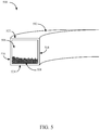
- FIG. 5 depicts a cross section 500 of a balancing channel 502 .
- the balancing channel 502 may be a four-sided rectangle with at least two sides being the same length or a four-sided square where all four sides are the same length.
- the balancing channel 502 may include freely moving objects 504 .
- the freely moving objects 504 may include one or more spherical objects (e.g., low-friction beads, etc.).
- At least a portion of a cross section 500 of the balancing channel 502 may include an outward surface 516 (e.g., a surface located on a far side, at a peripheral or outer portion of a wind turbine in relation to a vertical center of the wind turbine), an inward surface 518 facing a turbine shaft of the wind turbine, an upper surface 522 , and a lower surface 524 .
- an outward surface 516 e.g., a surface located on a far side, at a peripheral or outer portion of a wind turbine in relation to a vertical center of the wind turbine
- an inward surface 518 facing a turbine shaft of the wind turbine
- an upper surface 522 e.g., a lower surface 524
- FIG. 6 is a flow diagram illustrating one example of a method 600 for balancing a wind turbine.
- the method 600 may be implemented by the balancing channel illustrated in FIGS. 4 and/or 5 .
- method 600 may include transmitting, via a turbine shaft of a wind turbine, mechanical power to an alternator or generator as the wind turbine rotates.
- the wind turbine may be oriented as a vertical wind turbine, where the turbine shaft is oriented vertically.
- method 600 may include supporting, via a support structure, a vane shaft and the turbine shaft, the support structure coupling the vane shaft to the turbine shaft
- method 600 may include balancing the wind turbine based at least in part on a plurality of freely moving objects within a hollow chamber of a balancing tube.
- the balancing tube may be coupled to a vane shaft of the wind turbine.
- FIG. 7A depicts a side view 700 a of a vane shaft 708 in an airfoil 704 .
- vane shaft 708 may be a single rod running through a length of airfoil 704 .
- airfoil 704 may include a leading edge 726 and a trailing edge 728 .
- FIG. 7B depicts a top view 700 b of vane shaft 708 in airfoil 704 .
- vane shaft 708 may be positioned at a quarter chord point in airfoil 704 (e.g., one-fourth the distance from leading edge 726 to trailing edge 728 ).
- FIG. 8 depicts a side view 800 of upper vane shaft 808 - 1 and lower vane shaft 808 - 2 in airfoil 804 .
- vane shaft 808 - 1 may be separate from vane shaft 808 - 2 .
- a first portion of vane shaft 808 - 1 may insert into a top of airfoil 804 and a second portion of vane shaft 808 - 1 may extend out from the top of airfoil 804 .
- a first portion of vane shaft 808 - 2 may insert into a bottom of airfoil 804 and a second portion of vane shaft 808 - 2 may extend out from the bottom of airfoil 804 .
- vane shaft 808 - 1 and vane shaft 808 - 2 may be placed at a quarter chord point of airfoil 804 (e.g., one-fourth the distance from a leading edge of airfoil 804 and a trailing edge of airfoil 804 ).
- the terms “a” or “an,” as used in the specification and claims, are to be construed as meaning “at least one of.”
- the words “including” and “having,” as used in the specification and claims are interchangeable with and have the same meaning as the word “comprising.”
- the term “based on” as used in the specification and the claims is to be construed as meaning “based at least upon.”
Landscapes
- Engineering & Computer Science (AREA)
- Life Sciences & Earth Sciences (AREA)
- Sustainable Development (AREA)
- Sustainable Energy (AREA)
- Chemical & Material Sciences (AREA)
- Combustion & Propulsion (AREA)
- Mechanical Engineering (AREA)
- General Engineering & Computer Science (AREA)
- Wind Motors (AREA)
Abstract
Description
Claims (15)
Priority Applications (1)
| Application Number | Priority Date | Filing Date | Title |
|---|---|---|---|
| US16/130,329 US10655605B2 (en) | 2015-09-09 | 2018-09-13 | Balancing a wind turbine |
Applications Claiming Priority (2)
| Application Number | Priority Date | Filing Date | Title |
|---|---|---|---|
| US14/848,579 US20170067442A1 (en) | 2015-09-09 | 2015-09-09 | Apparatuses and methods for balancing a wind turbine assembly |
| US16/130,329 US10655605B2 (en) | 2015-09-09 | 2018-09-13 | Balancing a wind turbine |
Related Parent Applications (1)
| Application Number | Title | Priority Date | Filing Date |
|---|---|---|---|
| US14/848,579 Continuation-In-Part US20170067442A1 (en) | 2015-09-09 | 2015-09-09 | Apparatuses and methods for balancing a wind turbine assembly |
Publications (2)
| Publication Number | Publication Date |
|---|---|
| US20190040845A1 US20190040845A1 (en) | 2019-02-07 |
| US10655605B2 true US10655605B2 (en) | 2020-05-19 |
Family
ID=65229280
Family Applications (1)
| Application Number | Title | Priority Date | Filing Date |
|---|---|---|---|
| US16/130,329 Expired - Fee Related US10655605B2 (en) | 2015-09-09 | 2018-09-13 | Balancing a wind turbine |
Country Status (1)
| Country | Link |
|---|---|
| US (1) | US10655605B2 (en) |
Families Citing this family (3)
| Publication number | Priority date | Publication date | Assignee | Title |
|---|---|---|---|---|
| US10975839B2 (en) * | 2018-05-23 | 2021-04-13 | William Olen Fortner | Vertical axis wind turbines with V-cup shaped vanes, multi-turbine assemblies and related methods and systems |
| US10920751B2 (en) * | 2018-12-12 | 2021-02-16 | Ziaur Rahman | Orthogonal turbine having a speed adjusting member |
| CN117570935B (en) * | 2024-01-17 | 2024-03-15 | 水利部牧区水利科学研究所 | River and lake channel depth measuring equipment and measuring method |
Citations (15)
| Publication number | Priority date | Publication date | Assignee | Title |
|---|---|---|---|---|
| US3799619A (en) * | 1972-05-18 | 1974-03-26 | Wagner K | Vibration dampening assembly |
| US3970409A (en) * | 1975-03-26 | 1976-07-20 | Lawrence Peska Associates, Inc. | Wind power and flywheel apparatus |
| US4075909A (en) * | 1976-01-29 | 1978-02-28 | Deakin James E | Automatic shaft balancer |
| US5380156A (en) * | 1993-04-12 | 1995-01-10 | Iacovino; Robert | Ceiling fan balance apparatus |
| US5593281A (en) * | 1995-10-02 | 1997-01-14 | Jen-Lung D. Tai | Dynamic balancing apparatus for ceiling fans |
| US6213717B1 (en) * | 1999-10-08 | 2001-04-10 | San-Chi Wu | Balancing ring for a ceiling fan |
| US6827551B1 (en) * | 2000-02-01 | 2004-12-07 | The United States Of America As Represented By The Administrator Of The National Aeronautics And Space Administration | Self-tuning impact damper for rotating blades |
| US7220104B2 (en) * | 2004-12-30 | 2007-05-22 | General Electric Company | Vibration reduction system for a wind turbine |
| GB2437595A (en) * | 2006-04-25 | 2007-10-31 | Richard Cotton | Vertical axis wind turbine |
| US20090317251A1 (en) * | 2008-06-24 | 2009-12-24 | Kuei-Sheng Tsou | Stabilizing Apparatus For Vertical Axis Wind Turbine |
| US20100009835A1 (en) * | 2008-07-09 | 2010-01-14 | Hanlab Corporation | Automatic balancing centrifuge using balancer |
| US20100021303A1 (en) * | 2007-03-30 | 2010-01-28 | Thomas Steiniche Bjertrup Nielsen | Wind Turbine Comprising One Or More Oscillation Dampers |
| US20100310370A1 (en) * | 2009-06-03 | 2010-12-09 | Thomas Mellus Fenaughty | Turbine with vanes and tethers that adjust to the wind |
| US8984940B2 (en) * | 2012-04-04 | 2015-03-24 | Elliot Company | Passive dynamic inertial rotor balance system for turbomachinery |
| US20150211496A1 (en) * | 2014-01-28 | 2015-07-30 | Siemens Aktiengesellschaft | Damper of a wind turbine |
-
2018
- 2018-09-13 US US16/130,329 patent/US10655605B2/en not_active Expired - Fee Related
Patent Citations (15)
| Publication number | Priority date | Publication date | Assignee | Title |
|---|---|---|---|---|
| US3799619A (en) * | 1972-05-18 | 1974-03-26 | Wagner K | Vibration dampening assembly |
| US3970409A (en) * | 1975-03-26 | 1976-07-20 | Lawrence Peska Associates, Inc. | Wind power and flywheel apparatus |
| US4075909A (en) * | 1976-01-29 | 1978-02-28 | Deakin James E | Automatic shaft balancer |
| US5380156A (en) * | 1993-04-12 | 1995-01-10 | Iacovino; Robert | Ceiling fan balance apparatus |
| US5593281A (en) * | 1995-10-02 | 1997-01-14 | Jen-Lung D. Tai | Dynamic balancing apparatus for ceiling fans |
| US6213717B1 (en) * | 1999-10-08 | 2001-04-10 | San-Chi Wu | Balancing ring for a ceiling fan |
| US6827551B1 (en) * | 2000-02-01 | 2004-12-07 | The United States Of America As Represented By The Administrator Of The National Aeronautics And Space Administration | Self-tuning impact damper for rotating blades |
| US7220104B2 (en) * | 2004-12-30 | 2007-05-22 | General Electric Company | Vibration reduction system for a wind turbine |
| GB2437595A (en) * | 2006-04-25 | 2007-10-31 | Richard Cotton | Vertical axis wind turbine |
| US20100021303A1 (en) * | 2007-03-30 | 2010-01-28 | Thomas Steiniche Bjertrup Nielsen | Wind Turbine Comprising One Or More Oscillation Dampers |
| US20090317251A1 (en) * | 2008-06-24 | 2009-12-24 | Kuei-Sheng Tsou | Stabilizing Apparatus For Vertical Axis Wind Turbine |
| US20100009835A1 (en) * | 2008-07-09 | 2010-01-14 | Hanlab Corporation | Automatic balancing centrifuge using balancer |
| US20100310370A1 (en) * | 2009-06-03 | 2010-12-09 | Thomas Mellus Fenaughty | Turbine with vanes and tethers that adjust to the wind |
| US8984940B2 (en) * | 2012-04-04 | 2015-03-24 | Elliot Company | Passive dynamic inertial rotor balance system for turbomachinery |
| US20150211496A1 (en) * | 2014-01-28 | 2015-07-30 | Siemens Aktiengesellschaft | Damper of a wind turbine |
Also Published As
| Publication number | Publication date |
|---|---|
| US20190040845A1 (en) | 2019-02-07 |
Similar Documents
| Publication | Publication Date | Title |
|---|---|---|
| US10655605B2 (en) | Balancing a wind turbine | |
| US8322975B2 (en) | Vibration control apparatus of wind turbine generator and wind turbine generator | |
| CN107606054A (en) | A kind of self-adapting type torsional vibration damper and diesel engine | |
| RU2475415C2 (en) | Helicopter rotor with vibrations killer | |
| RU71386U1 (en) | WIND POWER PLANT WITH VERTICAL ROTOR | |
| US20170067442A1 (en) | Apparatuses and methods for balancing a wind turbine assembly | |
| CN204458789U (en) | The angled type reciprocating-piston compressor that a kind of balance of shaking force is optimized | |
| CN204255625U (en) | A kind of wheel rim centrifugal load model configuration for wheel disc test | |
| CN203894039U (en) | Resistance absorber for fatigue test of aerogenerator blade | |
| US8702396B2 (en) | Separative tidal current rotor blade | |
| RU2011149188A (en) | WIND TURBINE INSTALLATION | |
| CN108443412A (en) | A kind of dynamic self compensation balanced structure | |
| CN108212562A (en) | A kind of link-suspended basket centrifuge | |
| CN208185065U (en) | Fan frame base and its fan | |
| CN209521486U (en) | A kind of wheel rim with angle pore structure | |
| CN107882689B (en) | Wind power tower with middle supporting piece | |
| RU2552017C1 (en) | Wind engine | |
| DK3085956T3 (en) | Tower for a wind power plant as well as methods for erecting a wind power plant | |
| CN104617536A (en) | Power line wheel disk shock absorber | |
| RU2607449C2 (en) | Wind motor | |
| KR101042906B1 (en) | Rotor for wind turbine | |
| RU87767U1 (en) | SUSPENSION OF WIND STRIP STRIPPING | |
| US20170211549A1 (en) | Stabilizing a wind turbine assembly | |
| CN106100224B (en) | One kind consolidates, mute motor | |
| CN201934255U (en) | Spindle combination structure of vertical spindle windmill |
Legal Events
| Date | Code | Title | Description |
|---|---|---|---|
| FEPP | Fee payment procedure |
Free format text: ENTITY STATUS SET TO UNDISCOUNTED (ORIGINAL EVENT CODE: BIG.); ENTITY STATUS OF PATENT OWNER: SMALL ENTITY |
|
| FEPP | Fee payment procedure |
Free format text: ENTITY STATUS SET TO SMALL (ORIGINAL EVENT CODE: SMAL); ENTITY STATUS OF PATENT OWNER: SMALL ENTITY |
|
| STPP | Information on status: patent application and granting procedure in general |
Free format text: APPLICATION DISPATCHED FROM PREEXAM, NOT YET DOCKETED |
|
| STPP | Information on status: patent application and granting procedure in general |
Free format text: DOCKETED NEW CASE - READY FOR EXAMINATION |
|
| STPP | Information on status: patent application and granting procedure in general |
Free format text: NON FINAL ACTION MAILED |
|
| STPP | Information on status: patent application and granting procedure in general |
Free format text: RESPONSE TO NON-FINAL OFFICE ACTION ENTERED AND FORWARDED TO EXAMINER |
|
| ZAAA | Notice of allowance and fees due |
Free format text: ORIGINAL CODE: NOA |
|
| ZAAB | Notice of allowance mailed |
Free format text: ORIGINAL CODE: MN/=. |
|
| STPP | Information on status: patent application and granting procedure in general |
Free format text: PUBLICATIONS -- ISSUE FEE PAYMENT VERIFIED |
|
| STCF | Information on status: patent grant |
Free format text: PATENTED CASE |
|
| FEPP | Fee payment procedure |
Free format text: MAINTENANCE FEE REMINDER MAILED (ORIGINAL EVENT CODE: REM.); ENTITY STATUS OF PATENT OWNER: SMALL ENTITY |
|
| LAPS | Lapse for failure to pay maintenance fees |
Free format text: PATENT EXPIRED FOR FAILURE TO PAY MAINTENANCE FEES (ORIGINAL EVENT CODE: EXP.); ENTITY STATUS OF PATENT OWNER: SMALL ENTITY |
|
| STCH | Information on status: patent discontinuation |
Free format text: PATENT EXPIRED DUE TO NONPAYMENT OF MAINTENANCE FEES UNDER 37 CFR 1.362 |
|
| FP | Lapsed due to failure to pay maintenance fee |
Effective date: 20240519 |