EP2899284A1 - Metal recovery method - Google Patents
Metal recovery method Download PDFInfo
- Publication number
- EP2899284A1 EP2899284A1 EP13838170.2A EP13838170A EP2899284A1 EP 2899284 A1 EP2899284 A1 EP 2899284A1 EP 13838170 A EP13838170 A EP 13838170A EP 2899284 A1 EP2899284 A1 EP 2899284A1
- Authority
- EP
- European Patent Office
- Prior art keywords
- ladle
- metal
- molten metal
- refining
- area
- Prior art date
- Legal status (The legal status is an assumption and is not a legal conclusion. Google has not performed a legal analysis and makes no representation as to the accuracy of the status listed.)
- Granted
Links
Images


Classifications
-
- C—CHEMISTRY; METALLURGY
- C21—METALLURGY OF IRON
- C21C—PROCESSING OF PIG-IRON, e.g. REFINING, MANUFACTURE OF WROUGHT-IRON OR STEEL; TREATMENT IN MOLTEN STATE OF FERROUS ALLOYS
- C21C7/00—Treating molten ferrous alloys, e.g. steel, not covered by groups C21C1/00 - C21C5/00
- C21C7/0075—Treating in a ladle furnace, e.g. up-/reheating of molten steel within the ladle
-
- B—PERFORMING OPERATIONS; TRANSPORTING
- B22—CASTING; POWDER METALLURGY
- B22D—CASTING OF METALS; CASTING OF OTHER SUBSTANCES BY THE SAME PROCESSES OR DEVICES
- B22D41/00—Casting melt-holding vessels, e.g. ladles, tundishes, cups or the like
-
- B—PERFORMING OPERATIONS; TRANSPORTING
- B22—CASTING; POWDER METALLURGY
- B22D—CASTING OF METALS; CASTING OF OTHER SUBSTANCES BY THE SAME PROCESSES OR DEVICES
- B22D41/00—Casting melt-holding vessels, e.g. ladles, tundishes, cups or the like
- B22D41/001—Casting melt-holding vessels, e.g. ladles, tundishes, cups or the like devices for cleaning ladles
-
- B—PERFORMING OPERATIONS; TRANSPORTING
- B22—CASTING; POWDER METALLURGY
- B22D—CASTING OF METALS; CASTING OF OTHER SUBSTANCES BY THE SAME PROCESSES OR DEVICES
- B22D43/00—Mechanical cleaning, e.g. skimming of molten metals
-
- C—CHEMISTRY; METALLURGY
- C21—METALLURGY OF IRON
- C21C—PROCESSING OF PIG-IRON, e.g. REFINING, MANUFACTURE OF WROUGHT-IRON OR STEEL; TREATMENT IN MOLTEN STATE OF FERROUS ALLOYS
- C21C5/00—Manufacture of carbon-steel, e.g. plain mild steel, medium carbon steel or cast steel or stainless steel
- C21C5/005—Manufacture of stainless steel
-
- C—CHEMISTRY; METALLURGY
- C22—METALLURGY; FERROUS OR NON-FERROUS ALLOYS; TREATMENT OF ALLOYS OR NON-FERROUS METALS
- C22C—ALLOYS
- C22C38/00—Ferrous alloys, e.g. steel alloys
- C22C38/18—Ferrous alloys, e.g. steel alloys containing chromium
-
- F—MECHANICAL ENGINEERING; LIGHTING; HEATING; WEAPONS; BLASTING
- F27—FURNACES; KILNS; OVENS; RETORTS
- F27D—DETAILS OR ACCESSORIES OF FURNACES, KILNS, OVENS OR RETORTS, IN SO FAR AS THEY ARE OF KINDS OCCURRING IN MORE THAN ONE KIND OF FURNACE
- F27D25/00—Devices or methods for removing incrustations, e.g. slag, metal deposits, dust; Devices or methods for preventing the adherence of slag
-
- F—MECHANICAL ENGINEERING; LIGHTING; HEATING; WEAPONS; BLASTING
- F27—FURNACES; KILNS; OVENS; RETORTS
- F27D—DETAILS OR ACCESSORIES OF FURNACES, KILNS, OVENS OR RETORTS, IN SO FAR AS THEY ARE OF KINDS OCCURRING IN MORE THAN ONE KIND OF FURNACE
- F27D25/00—Devices or methods for removing incrustations, e.g. slag, metal deposits, dust; Devices or methods for preventing the adherence of slag
- F27D25/001—Devices or methods for removing incrustations, e.g. slag, metal deposits, dust; Devices or methods for preventing the adherence of slag comprising breaking tools, e.g. hammers, drills, scrapers
-
- C—CHEMISTRY; METALLURGY
- C21—METALLURGY OF IRON
- C21C—PROCESSING OF PIG-IRON, e.g. REFINING, MANUFACTURE OF WROUGHT-IRON OR STEEL; TREATMENT IN MOLTEN STATE OF FERROUS ALLOYS
- C21C1/00—Refining of pig-iron; Cast iron
- C21C1/06—Constructional features of mixers for pig-iron
-
- C—CHEMISTRY; METALLURGY
- C21—METALLURGY OF IRON
- C21C—PROCESSING OF PIG-IRON, e.g. REFINING, MANUFACTURE OF WROUGHT-IRON OR STEEL; TREATMENT IN MOLTEN STATE OF FERROUS ALLOYS
- C21C2200/00—Recycling of waste material
-
- C—CHEMISTRY; METALLURGY
- C21—METALLURGY OF IRON
- C21C—PROCESSING OF PIG-IRON, e.g. REFINING, MANUFACTURE OF WROUGHT-IRON OR STEEL; TREATMENT IN MOLTEN STATE OF FERROUS ALLOYS
- C21C5/00—Manufacture of carbon-steel, e.g. plain mild steel, medium carbon steel or cast steel or stainless steel
- C21C5/52—Manufacture of steel in electric furnaces
- C21C5/5294—General arrangement or layout of the electric melt shop
-
- Y—GENERAL TAGGING OF NEW TECHNOLOGICAL DEVELOPMENTS; GENERAL TAGGING OF CROSS-SECTIONAL TECHNOLOGIES SPANNING OVER SEVERAL SECTIONS OF THE IPC; TECHNICAL SUBJECTS COVERED BY FORMER USPC CROSS-REFERENCE ART COLLECTIONS [XRACs] AND DIGESTS
- Y02—TECHNOLOGIES OR APPLICATIONS FOR MITIGATION OR ADAPTATION AGAINST CLIMATE CHANGE
- Y02P—CLIMATE CHANGE MITIGATION TECHNOLOGIES IN THE PRODUCTION OR PROCESSING OF GOODS
- Y02P10/00—Technologies related to metal processing
- Y02P10/20—Recycling
Definitions
- the present invention relates to a metal recovery method for recovering, as a material, metal that adheres to a ladle.
- Patent literature 1 proposes a feature of transporting a ladle, in a state where no molten metal is held therein, to a ladle maintenance plant (off-line), where the metal adhering to the ladle is made to fall by using heavy machinery, and is removed from the ladle.
- the ladle maintenance plant the ladle is serviced in terms of, for instance, re-lining of refractory material, and spraying of monolithic refractory material.
- a ladle that has been transported to the ladle maintenance plant becomes a stand by ladle (resting ladle) until another ladle is transported to the ladle maintenance plant.
- the metal removed from the ladle is charged into a melting furnace, and as a result, the metal is melted and recovered as a material.
- Patent literature 1 Japanese Patent Application Publication No. H08-193210
- the molten metal in the ladle may in some instances be subjected to stir refining.
- Stir refining involves substantial flow of molten metal, and accordingly an even greater amount of metal adheres to the ladle. That is, metal may in some instances adhere in amounts that interfere with the operation of the ladle, even if the remaining life of the refractory material in the ladle is sufficient.
- metal removal is performed in the ladle maintenance plant, serving also the purpose of ladle maintenance.
- the ladle is repeatedly transported unnecessarily, which detracts from operational efficiency.
- heat from the ladle and the metal cannot be utilized effectively in operations.
- the metal recovery method according to the present invention is a metal recovery method for recovering, as a material, metal that adheres to a ladle in a series of processes in which molten metal is poured from a melting furnace into the ladle, the molten metal is subjected to stir refining inside the ladle, and the molten metal inside the ladle is poured into a refining furnace, the method comprising the step of, after pouring of the molten metal from the ladle into the refining furnace, having the metal adhering to the ladle fall into the ladle on-line, and pouring the molten metal from the melting furnace into the ladle into which the metal has fallen, to melt the metal and recover the metal as a material.
- metal adhering to the ladle is made to fall into the ladle on-line, and the molten metal is poured from a melting furnace into the ladle into which the metal has fallen; as a result, the metal is melted and recovered as a material.
- Fig. 1 is an explanatory diagram illustrating a steel mill to which the metal recovery method according to Embodiment 1 of the present invention is applied.
- the steel mill is provided with an electric furnace tapping area 1, a KR desulfurization area 2, a converter pouring area 3, a metal fall area 4 and a ladle maintenance area 5.
- a ladle 6 that transfers molten metal 6a within the steel mill is ordinarily transported in the order electric furnace tapping area 1, KR desulfurization area 2, converter pouring area 3 and metal fall area 4.
- the ladle 6 that is transported up to the metal fall area 4 is returned to the electric furnace tapping area 1.
- Fig. 1 illustrates one ladle 6, a plurality of ladles 6 may also be made to circulate in the order electric furnace tapping area 1, KR desulfurization area 2, converter pouring area 3 and metal fall area 4.
- the ladle 6 is transported to the ladle maintenance area 5 (off-line) when maintenance, for instance the exchange of refractory material, is required.
- a ladle 6 that has been transported to the ladle maintenance area 5 becomes a stand by ladle (resting ladle) until another ladle 6 is transported to the ladle maintenance area 5.
- Fig. 2 is an explanatory diagram illustrating an electric furnace tapping process that is performed in the electric furnace tapping area 1 of Fig. 1 .
- the electric furnace 10 is a melting furnace in which molten metal 6a is generated through melting of a material.
- the molten metal 6a that is generated in the electric furnace 10 is poured into the ladle 6.
- the molten metal 6a in the present embodiment is stainless-steel molten metal comprising 9 to 30 mass% of Cr and 1 to 4 mass% of C.
- Metal 6b has been already been fallen, into the ladle 6, by the time the molten metal 6a is poured into the ladle 6 from the electric furnace 10. As described in detail further on (see Fig. 5 ), the metal 6b is fallen into the ladle 6 as a result of a metal drop process that is performed in the metal fall area 4 (see Fig. 1 ). As a result of pouring of the molten metal 6a from the electric furnace 10 into the ladle 6 into which the metal 6b has been dropped, the metal 6b is melted and is recovered as a material.
- Fig. 3 is an explanatory diagram illustrating a KR desulfurization process that is performed in the KR desulfurization area 2 of Fig. 1 .
- KR desulfurization is performed in the KR desulfurization area 2.
- KR desulfurization denotes mechanical stir refining (in-ladle refining) in which a desulfurizing agent such as quicklime, soda ash, carbide, caustic soda, slaked lime or the like is supplied into the ladle 6 in which the molten metal 6a is held, followed by agitation by an impeller 20 that is immersed in the molten metal 6a.
- the desulfurization reaction in the molten metal 6a is promoted, and the sulfur concentration in the molten metal 6a is accordingly reduced, through agitation by the impeller 20.
- the liquid level of the molten metal 6a on the inner wall side in the ladle 6 rises during agitation by the impeller 20. Accordingly, the molten metal 6a comes in contact with the upper inner wall of the ladle 6, which is not touched by the molten metal 6a in the absence of agitation, and that is at a low temperature.
- the molten metal 6a that comes in contact with the upper inner wall is cooled by the upper inner wall, and adheres to the upper inner wall in the form of metal 6b.
- splash 21 is generated through rotation of the impeller 20 during agitation by the impeller 20. This splash 21 also becomes cooled at the upper inner wall, and adheres to the upper inner wall in the form of metal 6b.
- Fig. 4 is an explanatory diagram illustrating a converter pouring process that is performed in the converter pouring area 3 of Fig. 1 .
- a converter 30 is a refining furnace for further refining the molten metal 6a.
- the molten metal 6a inside the ladle 6 is poured into the converter 30 in the converter pouring area 3.
- the metal 6b constitutes a dam upon pouring of the molten metal 6a inside the ladle 6 into the converter 30, so that outpouring of the molten metal 6a from the ladle 6 is accordingly hindered.
- a large amount of metal 6b translates into increased overall weight of the ladle 6, and thus into a greater load on the crane that hoists the ladle 6.
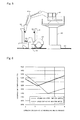
- Fig. 5 is an explanatory diagram illustrating a metal fall process that is performed in the metal fall area 4 of Fig. 1 .
- the metal fall area 4 is an area provided between the converter pouring area 3 and the electric furnace tapping area 1, in the transport route of the ladle 6 in the steel mill.
- a gate-type overdeck 40 is provided in the metal fall area 4.
- An articulated arm device 41 is provided on the gate-type overdeck 40.
- a metal faller 42 is attached to the leading end of a movable arm 41a of the articulated arm device 41. For instance, a crusher or the like that hits an object with a sharp bit is used herein as the metal faller 42.
- the ladle 6 out of which the molten metal 6a is poured into the converter 30 in the converter pouring area 3 described above is placed on a dolly 43, and is carried to the vicinity of the gate-type overdeck 40 along rails 44.
- the dolly 43 is fixed by a stopper 45 when the dolly 43 is at a position in the vicinity of the gate-type overdeck 40; thereupon, operation by an operator drives the metal faller 42, along with pivoting the movable arm 41a, and the metal 6b is fallen as a result into the ladle 6.
- the ladle 6 into which the metal 6b has been dropped is not herein a stand by ladle, and is returned to the electric furnace tapping area 1. In the present embodiment, thus, the molten metal 6a is poured from the ladle 6 into the converter 30, and thereafter, the metal 6b that adheres to the ladle 6 is thus dropped into the ladle 6 on-line (metal fall area 4).
- the feature wherein the metal 6b that adheres to the ladle 6 is dropped into the ladle 6 on-line denotes herein a feature wherein the metal 6b is dropped into the ladle 6 on the route along which the ladle 6 is transported from the converter 30 (refining furnace) to the electric furnace 10 (melting furnace), such that the ladle 6 is used continuously without being in a stand by state.
- the on-line falling of the metal 6b adhering to the ladle 6 makes it possible to avoid conveyance, into the ladle maintenance area 5 (off-line), of a ladle 6 that requires no maintenance, and to thus avoid loss of operational efficiency.
- the ladle 6 can return, to the electric furnace tapping area 1, in a state where the ladle 6 and the metal 6b are at a high temperature, and thus the heat of the ladle 6 and the metal 6b can be utilized even more effectively.
- the ladle 6 is transported to the ladle maintenance area 5, the ladle 6 and the metal 6b are cooled down to normal temperature, although in a case where the metal 6b is dropped into the ladle 6 on-line, as in the present embodiment, the temperature of the metal 6b at the time of pouring of the molten metal 6a from the electric furnace 10 into the ladle 6 ranges from about 500 to 700°C.
- the metal 6b adhering to the ladle 6 as a result of in-ladle stir refining characteristically has a higher proportion of valuable metals than that of a metal that adheres to the ladle 6 without undergoing in-ladle stir refining. Accordingly, the components of the molten metal 6a exhibit little turbulence even upon recovery of the metal 6b, in the form of a material, through melting by the molten metal 6a from the electric furnace 10, as illustrated in Fig. 2 .
- the metal 6b adheres to the ladle 6 in the KR desulfurization process, but splattered molten metal 6a adheres to the ladle 6, in the form of metal 6b, also in the electric furnace tapping process and the converter pouring process. That is, the metal 6b that is dropped in the metal fall process also encompasses metal 6b that adheres to the ladle 6 during pouring of the molten metal 6a from the electric furnace 10 into the ladle 6, and during pouring of the molten metal 6a inside the ladle 6 into the converter 30.
- Fig. 6 is a graph illustrating liquidus line temperatures of stainless-steel molten metal and ordinary-steel molten metal.
- the solid line represents a liquidus line of stainless-steel molten metal
- the dashed line represents a liquidus line of ordinary-steel molten metal.
- the carbon concentration after desulfurization is set in such a manner that the temperature denoted by the liquidus line is a lower temperature.
- the carbon concentration after desulfurization is set to range from about 1.0 mass% to 4.0 mass%, while in the case of production of ordinary steel, the carbon concentration after desulfurization is set to range from about 3.0 mass% to 5.5 mass%.
- the melting point of stainless-steel molten metal at a time where the carbon concentration after desulfurization ranges from about 1.0 mass% to 4.0 mass% is of about 1250°C, which is higher than the melting point of ordinary-steel molten metal (about 1150°C) at a time where the carbon concentration after desulfurization ranges from about 3.0 mass% to 5.5 mass%.
- the molten metal 6a adheres to the ladle 6, in the form of metal 6b, at a temperature that is higher than when ordinary steel is produced, and, accordingly, a greater amount of metal 6b adheres to the ladle 6.
- the molten metal 6a is poured from the ladle 6 into the converter 30 (refining furnace), and thereafter, the metal 6b adhering to the ladle 6 is dropped into the ladle 6 on-line, and the molten metal 6a is poured, from the electric furnace 10 (melting furnace), into the ladle 6 into which the metal 6b has been dropped.
- the metal 6b is melted and is recovered as a material. This therefore allows deterioration of operational efficiency to be avoided when stir refining is carried out, and allows more effective utilization of the heat of the ladle 6 and the metal 6b.
- the stir refining is KR desulfurization (mechanical stir refining) in which agitation is performed by the impeller 20 that is immersed in the molten metal 6a, a large amount of molten metal 6a adheres, in the form of metal 6b, to the ladle 6. Accordingly, being able to avoid a deterioration of operational efficiency through on-line dropping of the metal 6b into the ladle 6, when KR desulfurization is carried out, is extremely useful.
- KR desulfurization mechanical stir refining
- molten metal 6a that is poured from the electric furnace 10 into the ladle 6 is stainless-steel molten metal
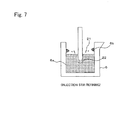
- Fig. 7 is an explanatory diagram illustrating injection stir refining in a metal recovery method according to Embodiment 2 of the present invention.
- KR desulfurization mechanical stir refining
- injection stir refining illustrated in Fig. 7 , can also be carried out.
- injection stir refining the molten metal 6a and a desulfurizing agent are agitated through blowing of gas is into the molten metal 6a through a submerged nozzle 22 that is immersed in the molten metal 6a.
- Splash 21 occurs as well in such injection stir refining, and the metal 6b adheres to the ladle 6.
- Other features are identical to those of Embodiment 1.
- the molten metal 6a was generated in the electric furnace 10, but molten metal may also be generated in another melting furnace, for instance a blast furnace or the like.
- the molten metal 6a was stainless-steel molten metal, but the molten metal may also be for instance, molten metal resulting from melting of ordinary steel, iron or the like.
Landscapes
- Engineering & Computer Science (AREA)
- Chemical & Material Sciences (AREA)
- Mechanical Engineering (AREA)
- Organic Chemistry (AREA)
- Materials Engineering (AREA)
- Metallurgy (AREA)
- General Engineering & Computer Science (AREA)
- Manufacturing & Machinery (AREA)
- Refinement Of Pig-Iron, Manufacture Of Cast Iron, And Steel Manufacture Other Than In Revolving Furnaces (AREA)
- Treatment Of Steel In Its Molten State (AREA)
- Manufacture And Refinement Of Metals (AREA)
- Processing Of Solid Wastes (AREA)
- Casting Support Devices, Ladles, And Melt Control Thereby (AREA)
Abstract
Description
- The present invention relates to a metal recovery method for recovering, as a material, metal that adheres to a ladle.
- Generally, a large amount of metal adheres to a ladle when the ladle is used over a plurality of charges, and it becomes accordingly necessary to remove the metal from the ladle.
Patent literature 1 proposes a feature of transporting a ladle, in a state where no molten metal is held therein, to a ladle maintenance plant (off-line), where the metal adhering to the ladle is made to fall by using heavy machinery, and is removed from the ladle. In the ladle maintenance plant, the ladle is serviced in terms of, for instance, re-lining of refractory material, and spraying of monolithic refractory material. A ladle that has been transported to the ladle maintenance plant becomes a stand by ladle (resting ladle) until another ladle is transported to the ladle maintenance plant. The metal removed from the ladle is charged into a melting furnace, and as a result, the metal is melted and recovered as a material. - Patent literature 1: Japanese Patent Application Publication No.
H08-193210 - In ironworks and steel mills, the molten metal in the ladle may in some instances be subjected to stir refining. Stir refining involves substantial flow of molten metal, and accordingly an even greater amount of metal adheres to the ladle. That is, metal may in some instances adhere in amounts that interfere with the operation of the ladle, even if the remaining life of the refractory material in the ladle is sufficient. In the method of
Patent literature 1, metal removal is performed in the ladle maintenance plant, serving also the purpose of ladle maintenance. When the method ofPatent literature 1 is applied directly in an instance where stir refining is carried out, the ladle is repeatedly transported unnecessarily, which detracts from operational efficiency. In a method that involves metal removal in the ladle maintenance plant, moreover, heat from the ladle and the metal cannot be utilized effectively in operations. - It is an object of the present invention, arrived at in order to solve the above problems, to provide a metal recovery method that allows avoiding deterioration of operational efficiency in a case where stir refining is carried out, and that allows utilizing the heat of a ladle and of metal more effectively.
- The metal recovery method according to the present invention is a metal recovery method for recovering, as a material, metal that adheres to a ladle in a series of processes in which molten metal is poured from a melting furnace into the ladle, the molten metal is subjected to stir refining inside the ladle, and the molten metal inside the ladle is poured into a refining furnace, the method comprising the step of, after pouring of the molten metal from the ladle into the refining furnace, having the metal adhering to the ladle fall into the ladle on-line, and pouring the molten metal from the melting furnace into the ladle into which the metal has fallen, to melt the metal and recover the metal as a material.
- In the metal recovery method of the present invention, after pouring of molten metal from a ladle into a refining furnace, metal adhering to the ladle is made to fall into the ladle on-line, and the molten metal is poured from a melting furnace into the ladle into which the metal has fallen; as a result, the metal is melted and recovered as a material. This allows, in consequence, avoiding deterioration of operational efficiency in a case where stir refining is carried out, and allows utilizing the heat of a ladle and of metal more effectively.
-
-
Fig. 1 is an explanatory diagram illustrating a steel mill to which a metal recovery method according toEmbodiment 1 of the present invention is applied; -
Fig. 2 is an explanatory diagram illustrating an electric furnace tapping process that is performed in an electric furnace tapping area ofFig. 1 ; -
Fig. 3 is an explanatory diagram illustrating a KR desulfurization process that is performed in a KR desulfurization area ofFig. 1 ; -
Fig. 4 is an explanatory diagram illustrating a converter pouring process that is performed in a converter pouring area ofFig. 1 ; -
Fig. 5 is an explanatory diagram illustrating a metal drop process that is performed in a metal fall area ofFig. 1 ; -
Fig. 6 is a graph illustrating liquidus line temperatures of stainless-steel molten metal and ordinary-steel molten metal; and -
Fig. 7 is an explanatory diagram illustrating injection stir refining in a metal recovery method according toEmbodiment 2 of the present invention. - Modes for carrying out the present invention will be explained next with reference to the accompanying drawings.
-
Fig. 1 is an explanatory diagram illustrating a steel mill to which the metal recovery method according toEmbodiment 1 of the present invention is applied. In the figure, the steel mill is provided with an electricfurnace tapping area 1, aKR desulfurization area 2, aconverter pouring area 3, ametal fall area 4 and aladle maintenance area 5. A ladle 6 that transfersmolten metal 6a within the steel mill is ordinarily transported in the order electricfurnace tapping area 1,KR desulfurization area 2,converter pouring area 3 andmetal fall area 4. The ladle 6 that is transported up to themetal fall area 4 is returned to the electricfurnace tapping area 1. AlthoughFig. 1 illustrates one ladle 6, a plurality of ladles 6 may also be made to circulate in the order electricfurnace tapping area 1,KR desulfurization area 2,converter pouring area 3 andmetal fall area 4. - The ladle 6 is transported to the ladle maintenance area 5 (off-line) when maintenance, for instance the exchange of refractory material, is required. A ladle 6 that has been transported to the
ladle maintenance area 5 becomes a stand by ladle (resting ladle) until another ladle 6 is transported to theladle maintenance area 5. - Next,
Fig. 2 is an explanatory diagram illustrating an electric furnace tapping process that is performed in the electricfurnace tapping area 1 ofFig. 1 . In the figure, theelectric furnace 10 is a melting furnace in whichmolten metal 6a is generated through melting of a material. In the electricfurnace tapping area 1, themolten metal 6a that is generated in theelectric furnace 10 is poured into the ladle 6. Themolten metal 6a in the present embodiment is stainless-steel molten metal comprising 9 to 30 mass% of Cr and 1 to 4 mass% of C. -
Metal 6b has been already been fallen, into the ladle 6, by the time themolten metal 6a is poured into the ladle 6 from theelectric furnace 10. As described in detail further on (seeFig. 5 ), themetal 6b is fallen into the ladle 6 as a result of a metal drop process that is performed in the metal fall area 4 (seeFig. 1 ). As a result of pouring of themolten metal 6a from theelectric furnace 10 into the ladle 6 into which themetal 6b has been dropped, themetal 6b is melted and is recovered as a material. - Next,
Fig. 3 is an explanatory diagram illustrating a KR desulfurization process that is performed in theKR desulfurization area 2 ofFig. 1 . In the figure, KR desulfurization is performed in theKR desulfurization area 2. Herein, KR desulfurization denotes mechanical stir refining (in-ladle refining) in which a desulfurizing agent such as quicklime, soda ash, carbide, caustic soda, slaked lime or the like is supplied into the ladle 6 in which themolten metal 6a is held, followed by agitation by animpeller 20 that is immersed in themolten metal 6a. The desulfurization reaction in themolten metal 6a is promoted, and the sulfur concentration in themolten metal 6a is accordingly reduced, through agitation by theimpeller 20. - The liquid level of the
molten metal 6a on the inner wall side in the ladle 6 rises during agitation by theimpeller 20. Accordingly, themolten metal 6a comes in contact with the upper inner wall of the ladle 6, which is not touched by themolten metal 6a in the absence of agitation, and that is at a low temperature. Themolten metal 6a that comes in contact with the upper inner wall is cooled by the upper inner wall, and adheres to the upper inner wall in the form ofmetal 6b. Further,splash 21 is generated through rotation of theimpeller 20 during agitation by theimpeller 20. Thissplash 21 also becomes cooled at the upper inner wall, and adheres to the upper inner wall in the form ofmetal 6b. - Next,
Fig. 4 is an explanatory diagram illustrating a converter pouring process that is performed in theconverter pouring area 3 ofFig. 1 . In the figure, aconverter 30 is a refining furnace for further refining themolten metal 6a. Themolten metal 6a inside the ladle 6 is poured into theconverter 30 in theconverter pouring area 3. In a case where a substantial amount ofmetal 6b adheres on the ladle 6, themetal 6b constitutes a dam upon pouring of themolten metal 6a inside the ladle 6 into theconverter 30, so that outpouring of themolten metal 6a from the ladle 6 is accordingly hindered. A large amount ofmetal 6b translates into increased overall weight of the ladle 6, and thus into a greater load on the crane that hoists the ladle 6. - Next,
Fig. 5 is an explanatory diagram illustrating a metal fall process that is performed in themetal fall area 4 ofFig. 1 . Themetal fall area 4 is an area provided between theconverter pouring area 3 and the electricfurnace tapping area 1, in the transport route of the ladle 6 in the steel mill. A gate-type overdeck 40 is provided in themetal fall area 4. An articulatedarm device 41 is provided on the gate-type overdeck 40. Ametal faller 42 is attached to the leading end of amovable arm 41a of the articulatedarm device 41. For instance, a crusher or the like that hits an object with a sharp bit is used herein as themetal faller 42. - The ladle 6 out of which the
molten metal 6a is poured into theconverter 30 in theconverter pouring area 3 described above is placed on adolly 43, and is carried to the vicinity of the gate-type overdeck 40 along rails 44. Thedolly 43 is fixed by astopper 45 when thedolly 43 is at a position in the vicinity of the gate-type overdeck 40; thereupon, operation by an operator drives themetal faller 42, along with pivoting themovable arm 41a, and themetal 6b is fallen as a result into the ladle 6. The ladle 6 into which themetal 6b has been dropped is not herein a stand by ladle, and is returned to the electricfurnace tapping area 1. In the present embodiment, thus, themolten metal 6a is poured from the ladle 6 into theconverter 30, and thereafter, themetal 6b that adheres to the ladle 6 is thus dropped into the ladle 6 on-line (metal fall area 4). - Specifically, the feature wherein the
metal 6b that adheres to the ladle 6 is dropped into the ladle 6 on-line denotes herein a feature wherein themetal 6b is dropped into the ladle 6 on the route along which the ladle 6 is transported from the converter 30 (refining furnace) to the electric furnace 10 (melting furnace), such that the ladle 6 is used continuously without being in a stand by state. As a result, the on-line falling of themetal 6b adhering to the ladle 6 makes it possible to avoid conveyance, into the ladle maintenance area 5 (off-line), of a ladle 6 that requires no maintenance, and to thus avoid loss of operational efficiency. Further, the ladle 6 can return, to the electricfurnace tapping area 1, in a state where the ladle 6 and themetal 6b are at a high temperature, and thus the heat of the ladle 6 and themetal 6b can be utilized even more effectively. When the ladle 6 is transported to theladle maintenance area 5, the ladle 6 and themetal 6b are cooled down to normal temperature, although in a case where themetal 6b is dropped into the ladle 6 on-line, as in the present embodiment, the temperature of themetal 6b at the time of pouring of themolten metal 6a from theelectric furnace 10 into the ladle 6 ranges from about 500 to 700°C. Themetal 6b adhering to the ladle 6 as a result of in-ladle stir refining characteristically has a higher proportion of valuable metals than that of a metal that adheres to the ladle 6 without undergoing in-ladle stir refining. Accordingly, the components of themolten metal 6a exhibit little turbulence even upon recovery of themetal 6b, in the form of a material, through melting by themolten metal 6a from theelectric furnace 10, as illustrated inFig. 2 . - In the explanation above, the
metal 6b adheres to the ladle 6 in the KR desulfurization process, but splatteredmolten metal 6a adheres to the ladle 6, in the form ofmetal 6b, also in the electric furnace tapping process and the converter pouring process. That is, themetal 6b that is dropped in the metal fall process also encompassesmetal 6b that adheres to the ladle 6 during pouring of themolten metal 6a from theelectric furnace 10 into the ladle 6, and during pouring of themolten metal 6a inside the ladle 6 into theconverter 30. - Next,
Fig. 6 is a graph illustrating liquidus line temperatures of stainless-steel molten metal and ordinary-steel molten metal. In the figure, the solid line represents a liquidus line of stainless-steel molten metal, and the dashed line represents a liquidus line of ordinary-steel molten metal. - Generally, the carbon concentration after desulfurization is set in such a manner that the temperature denoted by the liquidus line is a lower temperature. In the case of stainless steel production, specifically, the carbon concentration after desulfurization is set to range from about 1.0 mass% to 4.0 mass%, while in the case of production of ordinary steel, the carbon concentration after desulfurization is set to range from about 3.0 mass% to 5.5 mass%.
- As illustrated in
Fig. 6 , the melting point of stainless-steel molten metal at a time where the carbon concentration after desulfurization ranges from about 1.0 mass% to 4.0 mass% is of about 1250°C, which is higher than the melting point of ordinary-steel molten metal (about 1150°C) at a time where the carbon concentration after desulfurization ranges from about 3.0 mass% to 5.5 mass%. Upon production of stainless steel, thus, themolten metal 6a adheres to the ladle 6, in the form ofmetal 6b, at a temperature that is higher than when ordinary steel is produced, and, accordingly, a greater amount ofmetal 6b adheres to the ladle 6. In the production of stainless steel, as a result, it is necessary to remove themetal 6b at a higher frequency than is the case in the production of ordinary steel. Avoiding deterioration of operational efficiency, through on-line dropping of themetal 6b into the ladle 6, as in the method of the present embodiment, is therefore particularly advantageous in the production of stainless steel. - In such a metal recovery method, the
molten metal 6a is poured from the ladle 6 into the converter 30 (refining furnace), and thereafter, themetal 6b adhering to the ladle 6 is dropped into the ladle 6 on-line, and themolten metal 6a is poured, from the electric furnace 10 (melting furnace), into the ladle 6 into which themetal 6b has been dropped. As a result, themetal 6b is melted and is recovered as a material. This therefore allows deterioration of operational efficiency to be avoided when stir refining is carried out, and allows more effective utilization of the heat of the ladle 6 and themetal 6b. In conventional methods, it has been necessary to significantly tilt the ladle 6 in order to remove themetal 6b from the ladle 6. In the method of the present embodiment, however, such an operation can be rendered unnecessary, and operational efficiency can be accordingly improved. - Herein, as the stir refining is KR desulfurization (mechanical stir refining) in which agitation is performed by the
impeller 20 that is immersed in themolten metal 6a, a large amount ofmolten metal 6a adheres, in the form ofmetal 6b, to the ladle 6. Accordingly, being able to avoid a deterioration of operational efficiency through on-line dropping of themetal 6b into the ladle 6, when KR desulfurization is carried out, is extremely useful. - Further, as the
molten metal 6a that is poured from theelectric furnace 10 into the ladle 6 is stainless-steel molten metal, a greater amount ofmolten metal 6a adheres to the ladle 6, as themetal 6b, than is the case in the production of ordinary steel. Accordingly, being able to avoid a deterioration of operational efficiency through on-line dropping of themetal 6b into the ladle 6, in a case where themolten metal 6a is stainless-steel molten metal, is extremely useful. -
Fig. 7 is an explanatory diagram illustrating injection stir refining in a metal recovery method according toEmbodiment 2 of the present invention. In the explanation ofEmbodiment 1, KR desulfurization (mechanical stir refining) was performed as in-ladle stir refining, but injection stir refining, illustrated inFig. 7 , can also be carried out. In injection stir refining, themolten metal 6a and a desulfurizing agent are agitated through blowing of gas is into themolten metal 6a through a submergednozzle 22 that is immersed in themolten metal 6a.Splash 21 occurs as well in such injection stir refining, and themetal 6b adheres to the ladle 6. Other features are identical to those ofEmbodiment 1. - Also, cases where injection stir refining is performed as in-ladle stir refining, a large amount of
molten metal 6a adheres, in the form of themetal 6b, to the ladle 6, and accordingly, being able to avoid deterioration of operational efficiency, through on-line dropping of themetal 6b into the ladle 6, is extremely useful. - In the explanations of
Embodiments molten metal 6a was generated in theelectric furnace 10, but molten metal may also be generated in another melting furnace, for instance a blast furnace or the like. - In the explanations of
Embodiments molten metal 6a was stainless-steel molten metal, but the molten metal may also be for instance, molten metal resulting from melting of ordinary steel, iron or the like.
Claims (3)
- A metal recovery method for recovering, as a material, metal that adheres to a ladle in a series of processes in which molten metal is poured from a melting furnace into the ladle, the molten metal is subjected to stir refining inside the ladle, and the molten metal inside the ladle is poured into a refining furnace, the method comprising the steps of:after pouring of the molten metal from the ladle into the refining furnace, dropping the metal adhering to the ladle into the ladle on-line, and pouring the molten metal from the melting furnace into the ladle into which the metal has been dropped, to melt the metal and recover the metal as a material.
- The metal recovery method according to claim 1, wherein the stir refining is mechanical stir refining in which agitation is performed by an impeller that is immersed in the molten metal, or injection stir refining in which a gas is blown into the molten metal.
- The metal recovery method according to claim 1 or 2, wherein the molten metal that is poured from the melting furnace into the ladle is stainless-steel molten metal.
Applications Claiming Priority (2)
| Application Number | Priority Date | Filing Date | Title |
|---|---|---|---|
| JP2012207721A JP5723342B2 (en) | 2012-09-21 | 2012-09-21 | Bullet collection method |
| PCT/JP2013/070163 WO2014045710A1 (en) | 2012-09-21 | 2013-07-25 | Metal recovery method |
Publications (3)
| Publication Number | Publication Date |
|---|---|
| EP2899284A1 true EP2899284A1 (en) | 2015-07-29 |
| EP2899284A4 EP2899284A4 (en) | 2016-05-25 |
| EP2899284B1 EP2899284B1 (en) | 2018-02-28 |
Family
ID=50341036
Family Applications (1)
| Application Number | Title | Priority Date | Filing Date |
|---|---|---|---|
| EP13838170.2A Active EP2899284B1 (en) | 2012-09-21 | 2013-07-25 | Metal recovery method |
Country Status (11)
| Country | Link |
|---|---|
| US (1) | US9663838B2 (en) |
| EP (1) | EP2899284B1 (en) |
| JP (1) | JP5723342B2 (en) |
| KR (1) | KR102096128B1 (en) |
| CN (1) | CN104704132B (en) |
| ES (1) | ES2668862T3 (en) |
| IN (1) | IN2015KN00703A (en) |
| MY (1) | MY197137A (en) |
| TW (1) | TWI593805B (en) |
| WO (1) | WO2014045710A1 (en) |
| ZA (1) | ZA201502037B (en) |
Families Citing this family (2)
| Publication number | Priority date | Publication date | Assignee | Title |
|---|---|---|---|---|
| CN108106448B (en) * | 2017-12-18 | 2019-07-26 | 巢湖云海镁业有限公司 | A lower top slag machine for vacuum smelting reduction device |
| CN118896806A (en) * | 2024-07-12 | 2024-11-05 | 上海图灵智造机器人股份有限公司 | A molten steel sample sampling system |
Family Cites Families (18)
| Publication number | Priority date | Publication date | Assignee | Title |
|---|---|---|---|---|
| US2564037A (en) * | 1947-10-28 | 1951-08-14 | Air Reduction | Method of removing skulls from metal receptacles |
| GB934163A (en) * | 1961-07-11 | 1963-08-14 | Foseco Int | Treatment of vessels used for holding molten metal |
| JPS6164811A (en) * | 1984-09-03 | 1986-04-03 | Nippon Kokan Kk <Nkk> | Desulfurization method for molten steel |
| JP3293383B2 (en) * | 1995-01-18 | 2002-06-17 | 日本鋼管株式会社 | How to use hot metal slag |
| JPH09314316A (en) * | 1996-05-30 | 1997-12-09 | Kawasaki Steel Corp | Removal method of deposits in molten steel ladle |
| JP3365498B2 (en) * | 1999-12-24 | 2003-01-14 | 株式会社フジコー | Ingot removal equipment |
| KR20020032827A (en) * | 2000-10-27 | 2002-05-04 | 이구택 | Scale recycle apparatus of electric furnace roof |
| JP2003001414A (en) * | 2001-06-22 | 2003-01-08 | Fujikoo:Kk | Equipment for removing deposits from the hot metal holding vessel |
| JP3643553B2 (en) * | 2001-11-29 | 2005-04-27 | 新日本製鐵株式会社 | KR impeller deposit removing apparatus and method |
| KR100829959B1 (en) * | 2001-12-22 | 2008-05-16 | 주식회사 포스코 | Ladle Top Stacker Now Remover |
| KR100778734B1 (en) * | 2001-12-24 | 2007-11-23 | 주식회사 포스코 | Ladle Cover and Lance Now Remover |
| CN101389773B (en) * | 2004-10-11 | 2011-04-13 | 技术资源有限公司 | Electric arc furnace steelmaking |
| JP4936787B2 (en) * | 2006-05-12 | 2012-05-23 | 日新製鋼株式会社 | Desulfurization refining agent and desulfurization method for Cr-containing hot metal |
| JP4714655B2 (en) * | 2006-09-05 | 2011-06-29 | 新日本製鐵株式会社 | Desulfurization method for chromium-containing molten iron |
| JP4999483B2 (en) * | 2007-02-07 | 2012-08-15 | 日新製鋼株式会社 | Manufacturing method of stainless steel |
| JP5436302B2 (en) * | 2010-03-29 | 2014-03-05 | 日新製鋼株式会社 | Chromium-containing hot metal and slag treatment method |
| JP5606152B2 (en) * | 2010-05-24 | 2014-10-15 | 株式会社神戸製鋼所 | How to remove ladles from ladle |
| JP5309172B2 (en) * | 2011-03-08 | 2013-10-09 | 日新製鋼株式会社 | Impeller speed control method |
-
2012
- 2012-09-21 JP JP2012207721A patent/JP5723342B2/en active Active
-
2013
- 2013-07-25 WO PCT/JP2013/070163 patent/WO2014045710A1/en not_active Ceased
- 2013-07-25 CN CN201380049163.2A patent/CN104704132B/en active Active
- 2013-07-25 US US14/429,556 patent/US9663838B2/en active Active
- 2013-07-25 KR KR1020157008515A patent/KR102096128B1/en active Active
- 2013-07-25 MY MYPI2015700848A patent/MY197137A/en unknown
- 2013-07-25 EP EP13838170.2A patent/EP2899284B1/en active Active
- 2013-07-25 IN IN703KON2015 patent/IN2015KN00703A/en unknown
- 2013-07-25 ES ES13838170.2T patent/ES2668862T3/en active Active
- 2013-07-30 TW TW102127214A patent/TWI593805B/en active
-
2015
- 2015-03-25 ZA ZA2015/02037A patent/ZA201502037B/en unknown
Also Published As
| Publication number | Publication date |
|---|---|
| CN104704132B (en) | 2016-09-28 |
| ZA201502037B (en) | 2018-05-30 |
| WO2014045710A1 (en) | 2014-03-27 |
| EP2899284A4 (en) | 2016-05-25 |
| IN2015KN00703A (en) | 2015-07-17 |
| EP2899284B1 (en) | 2018-02-28 |
| MY197137A (en) | 2023-05-26 |
| KR102096128B1 (en) | 2020-04-01 |
| JP2014062298A (en) | 2014-04-10 |
| JP5723342B2 (en) | 2015-05-27 |
| US20150247213A1 (en) | 2015-09-03 |
| TW201413000A (en) | 2014-04-01 |
| KR20150054882A (en) | 2015-05-20 |
| US9663838B2 (en) | 2017-05-30 |
| ES2668862T3 (en) | 2018-05-22 |
| CN104704132A (en) | 2015-06-10 |
| TWI593805B (en) | 2017-08-01 |
Similar Documents
| Publication | Publication Date | Title |
|---|---|---|
| RU2734853C2 (en) | Cast iron production method, device for its production and cast iron produced by said method | |
| CN108300929A (en) | A kind of processing method of plank and its feeding mechanism of continuous casting installation for casting | |
| JP6136379B2 (en) | Molten steel manufacturing method | |
| CN103695589A (en) | Method for removing titanium in molten iron | |
| US9663838B2 (en) | Metal recovery method | |
| JP5122842B2 (en) | Method for preventing smelting top cover | |
| US20140190312A1 (en) | Method and apparatus for dephosphorising liquid hot metal such as liquid blast furnace iron | |
| JP5407186B2 (en) | Dust generation prevention method in remaining hot water return work | |
| JP4254412B2 (en) | Hot metal desulfurization method | |
| CN112176149B (en) | Liquid metal refining device, liquid metal smelting system and refining method | |
| JP4442368B2 (en) | Melting method of large cold iron source in hot metal transfer container | |
| JP5145736B2 (en) | Dephosphorization method of hot metal in converter type refining furnace | |
| JP2015160981A (en) | Preliminary treatment method for molten pig iron | |
| CN104099434A (en) | Dust suppression treatment method for molten iron desulfuration residue and device utilized for method | |
| JP4946314B2 (en) | Method for recovering bullion from CaO desulfurization slag | |
| JP4205818B2 (en) | Dephosphorization method for hot metal using decarburized slag | |
| JP6414097B2 (en) | How to reuse molten steel | |
| JP5749546B2 (en) | Method for removing bottom deposits of iron and tin-containing copper processing furnaces | |
| CA2583507C (en) | Electric arc furnace steelmaking | |
| JP2004018915A (en) | Refining method of molten metal | |
| CN118653028A (en) | A method for recycling slag from converter molten iron tank | |
| SU1027227A1 (en) | Method for making steel | |
| Hurley et al. | Improved Corrosion Resistance of Alumina Refractories | |
| Gustafson | Easing the ladle metallurgy bottleneck | |
| JP2006131959A (en) | Method for producing highly clean steel using vacuum degassing |
Legal Events
| Date | Code | Title | Description |
|---|---|---|---|
| PUAI | Public reference made under article 153(3) epc to a published international application that has entered the european phase |
Free format text: ORIGINAL CODE: 0009012 |
|
| 17P | Request for examination filed |
Effective date: 20150309 |
|
| AK | Designated contracting states |
Kind code of ref document: A1 Designated state(s): AL AT BE BG CH CY CZ DE DK EE ES FI FR GB GR HR HU IE IS IT LI LT LU LV MC MK MT NL NO PL PT RO RS SE SI SK SM TR |
|
| AX | Request for extension of the european patent |
Extension state: BA ME |
|
| DAX | Request for extension of the european patent (deleted) | ||
| RA4 | Supplementary search report drawn up and despatched (corrected) |
Effective date: 20160425 |
|
| RIC1 | Information provided on ipc code assigned before grant |
Ipc: C22C 38/18 20060101ALI20160419BHEP Ipc: B22D 43/00 20060101ALI20160419BHEP Ipc: B22D 41/00 20060101ALI20160419BHEP Ipc: C21C 5/00 20060101ALI20160419BHEP Ipc: C21C 1/06 20060101ALI20160419BHEP Ipc: C21C 5/52 20060101ALI20160419BHEP Ipc: C21C 7/00 20060101ALI20160419BHEP Ipc: F27D 25/00 20100101ALI20160419BHEP Ipc: C21C 1/02 20060101AFI20160419BHEP |
|
| GRAP | Despatch of communication of intention to grant a patent |
Free format text: ORIGINAL CODE: EPIDOSNIGR1 |
|
| INTG | Intention to grant announced |
Effective date: 20170926 |
|
| GRAS | Grant fee paid |
Free format text: ORIGINAL CODE: EPIDOSNIGR3 |
|
| GRAA | (expected) grant |
Free format text: ORIGINAL CODE: 0009210 |
|
| AK | Designated contracting states |
Kind code of ref document: B1 Designated state(s): AL AT BE BG CH CY CZ DE DK EE ES FI FR GB GR HR HU IE IS IT LI LT LU LV MC MK MT NL NO PL PT RO RS SE SI SK SM TR |
|
| REG | Reference to a national code |
Ref country code: GB Ref legal event code: FG4D Ref country code: CH Ref legal event code: EP |
|
| REG | Reference to a national code |
Ref country code: AT Ref legal event code: REF Ref document number: 974193 Country of ref document: AT Kind code of ref document: T Effective date: 20180315 |
|
| REG | Reference to a national code |
Ref country code: IE Ref legal event code: FG4D |
|
| REG | Reference to a national code |
Ref country code: DE Ref legal event code: R096 Ref document number: 602013033829 Country of ref document: DE |
|
| REG | Reference to a national code |
Ref country code: SE Ref legal event code: TRGR |
|
| REG | Reference to a national code |
Ref country code: ES Ref legal event code: FG2A Ref document number: 2668862 Country of ref document: ES Kind code of ref document: T3 Effective date: 20180522 |
|
| REG | Reference to a national code |
Ref country code: NL Ref legal event code: MP Effective date: 20180228 |
|
| REG | Reference to a national code |
Ref country code: LT Ref legal event code: MG4D |
|
| REG | Reference to a national code |
Ref country code: AT Ref legal event code: MK05 Ref document number: 974193 Country of ref document: AT Kind code of ref document: T Effective date: 20180228 |
|
| PG25 | Lapsed in a contracting state [announced via postgrant information from national office to epo] |
Ref country code: NO Free format text: LAPSE BECAUSE OF FAILURE TO SUBMIT A TRANSLATION OF THE DESCRIPTION OR TO PAY THE FEE WITHIN THE PRESCRIBED TIME-LIMIT Effective date: 20180528 Ref country code: HR Free format text: LAPSE BECAUSE OF FAILURE TO SUBMIT A TRANSLATION OF THE DESCRIPTION OR TO PAY THE FEE WITHIN THE PRESCRIBED TIME-LIMIT Effective date: 20180228 Ref country code: LT Free format text: LAPSE BECAUSE OF FAILURE TO SUBMIT A TRANSLATION OF THE DESCRIPTION OR TO PAY THE FEE WITHIN THE PRESCRIBED TIME-LIMIT Effective date: 20180228 Ref country code: NL Free format text: LAPSE BECAUSE OF FAILURE TO SUBMIT A TRANSLATION OF THE DESCRIPTION OR TO PAY THE FEE WITHIN THE PRESCRIBED TIME-LIMIT Effective date: 20180228 Ref country code: CY Free format text: LAPSE BECAUSE OF FAILURE TO SUBMIT A TRANSLATION OF THE DESCRIPTION OR TO PAY THE FEE WITHIN THE PRESCRIBED TIME-LIMIT Effective date: 20180228 |
|
| PG25 | Lapsed in a contracting state [announced via postgrant information from national office to epo] |
Ref country code: GR Free format text: LAPSE BECAUSE OF FAILURE TO SUBMIT A TRANSLATION OF THE DESCRIPTION OR TO PAY THE FEE WITHIN THE PRESCRIBED TIME-LIMIT Effective date: 20180529 Ref country code: LV Free format text: LAPSE BECAUSE OF FAILURE TO SUBMIT A TRANSLATION OF THE DESCRIPTION OR TO PAY THE FEE WITHIN THE PRESCRIBED TIME-LIMIT Effective date: 20180228 Ref country code: AT Free format text: LAPSE BECAUSE OF FAILURE TO SUBMIT A TRANSLATION OF THE DESCRIPTION OR TO PAY THE FEE WITHIN THE PRESCRIBED TIME-LIMIT Effective date: 20180228 Ref country code: RS Free format text: LAPSE BECAUSE OF FAILURE TO SUBMIT A TRANSLATION OF THE DESCRIPTION OR TO PAY THE FEE WITHIN THE PRESCRIBED TIME-LIMIT Effective date: 20180228 Ref country code: BG Free format text: LAPSE BECAUSE OF FAILURE TO SUBMIT A TRANSLATION OF THE DESCRIPTION OR TO PAY THE FEE WITHIN THE PRESCRIBED TIME-LIMIT Effective date: 20180528 |
|
| PG25 | Lapsed in a contracting state [announced via postgrant information from national office to epo] |
Ref country code: EE Free format text: LAPSE BECAUSE OF FAILURE TO SUBMIT A TRANSLATION OF THE DESCRIPTION OR TO PAY THE FEE WITHIN THE PRESCRIBED TIME-LIMIT Effective date: 20180228 Ref country code: PL Free format text: LAPSE BECAUSE OF FAILURE TO SUBMIT A TRANSLATION OF THE DESCRIPTION OR TO PAY THE FEE WITHIN THE PRESCRIBED TIME-LIMIT Effective date: 20180228 Ref country code: AL Free format text: LAPSE BECAUSE OF FAILURE TO SUBMIT A TRANSLATION OF THE DESCRIPTION OR TO PAY THE FEE WITHIN THE PRESCRIBED TIME-LIMIT Effective date: 20180228 Ref country code: RO Free format text: LAPSE BECAUSE OF FAILURE TO SUBMIT A TRANSLATION OF THE DESCRIPTION OR TO PAY THE FEE WITHIN THE PRESCRIBED TIME-LIMIT Effective date: 20180228 |
|
| REG | Reference to a national code |
Ref country code: DE Ref legal event code: R097 Ref document number: 602013033829 Country of ref document: DE |
|
| PG25 | Lapsed in a contracting state [announced via postgrant information from national office to epo] |
Ref country code: CZ Free format text: LAPSE BECAUSE OF FAILURE TO SUBMIT A TRANSLATION OF THE DESCRIPTION OR TO PAY THE FEE WITHIN THE PRESCRIBED TIME-LIMIT Effective date: 20180228 Ref country code: DK Free format text: LAPSE BECAUSE OF FAILURE TO SUBMIT A TRANSLATION OF THE DESCRIPTION OR TO PAY THE FEE WITHIN THE PRESCRIBED TIME-LIMIT Effective date: 20180228 Ref country code: SM Free format text: LAPSE BECAUSE OF FAILURE TO SUBMIT A TRANSLATION OF THE DESCRIPTION OR TO PAY THE FEE WITHIN THE PRESCRIBED TIME-LIMIT Effective date: 20180228 Ref country code: SK Free format text: LAPSE BECAUSE OF FAILURE TO SUBMIT A TRANSLATION OF THE DESCRIPTION OR TO PAY THE FEE WITHIN THE PRESCRIBED TIME-LIMIT Effective date: 20180228 |
|
| PLBE | No opposition filed within time limit |
Free format text: ORIGINAL CODE: 0009261 |
|
| STAA | Information on the status of an ep patent application or granted ep patent |
Free format text: STATUS: NO OPPOSITION FILED WITHIN TIME LIMIT |
|
| 26N | No opposition filed |
Effective date: 20181129 |
|
| PG25 | Lapsed in a contracting state [announced via postgrant information from national office to epo] |
Ref country code: SI Free format text: LAPSE BECAUSE OF FAILURE TO SUBMIT A TRANSLATION OF THE DESCRIPTION OR TO PAY THE FEE WITHIN THE PRESCRIBED TIME-LIMIT Effective date: 20180228 |
|
| REG | Reference to a national code |
Ref country code: CH Ref legal event code: PL |
|
| GBPC | Gb: european patent ceased through non-payment of renewal fee |
Effective date: 20180725 |
|
| PG25 | Lapsed in a contracting state [announced via postgrant information from national office to epo] |
Ref country code: LU Free format text: LAPSE BECAUSE OF NON-PAYMENT OF DUE FEES Effective date: 20180725 Ref country code: MC Free format text: LAPSE BECAUSE OF FAILURE TO SUBMIT A TRANSLATION OF THE DESCRIPTION OR TO PAY THE FEE WITHIN THE PRESCRIBED TIME-LIMIT Effective date: 20180228 |
|
| REG | Reference to a national code |
Ref country code: IE Ref legal event code: MM4A |
|
| PG25 | Lapsed in a contracting state [announced via postgrant information from national office to epo] |
Ref country code: FR Free format text: LAPSE BECAUSE OF NON-PAYMENT OF DUE FEES Effective date: 20180731 Ref country code: LI Free format text: LAPSE BECAUSE OF NON-PAYMENT OF DUE FEES Effective date: 20180731 Ref country code: CH Free format text: LAPSE BECAUSE OF NON-PAYMENT OF DUE FEES Effective date: 20180731 Ref country code: IE Free format text: LAPSE BECAUSE OF NON-PAYMENT OF DUE FEES Effective date: 20180725 Ref country code: GB Free format text: LAPSE BECAUSE OF NON-PAYMENT OF DUE FEES Effective date: 20180725 |
|
| PG25 | Lapsed in a contracting state [announced via postgrant information from national office to epo] |
Ref country code: MT Free format text: LAPSE BECAUSE OF NON-PAYMENT OF DUE FEES Effective date: 20180725 |
|
| PG25 | Lapsed in a contracting state [announced via postgrant information from national office to epo] |
Ref country code: TR Free format text: LAPSE BECAUSE OF FAILURE TO SUBMIT A TRANSLATION OF THE DESCRIPTION OR TO PAY THE FEE WITHIN THE PRESCRIBED TIME-LIMIT Effective date: 20180228 |
|
| PG25 | Lapsed in a contracting state [announced via postgrant information from national office to epo] |
Ref country code: PT Free format text: LAPSE BECAUSE OF FAILURE TO SUBMIT A TRANSLATION OF THE DESCRIPTION OR TO PAY THE FEE WITHIN THE PRESCRIBED TIME-LIMIT Effective date: 20180228 |
|
| PG25 | Lapsed in a contracting state [announced via postgrant information from national office to epo] |
Ref country code: MK Free format text: LAPSE BECAUSE OF NON-PAYMENT OF DUE FEES Effective date: 20180228 Ref country code: HU Free format text: LAPSE BECAUSE OF FAILURE TO SUBMIT A TRANSLATION OF THE DESCRIPTION OR TO PAY THE FEE WITHIN THE PRESCRIBED TIME-LIMIT; INVALID AB INITIO Effective date: 20130725 |
|
| PG25 | Lapsed in a contracting state [announced via postgrant information from national office to epo] |
Ref country code: IS Free format text: LAPSE BECAUSE OF FAILURE TO SUBMIT A TRANSLATION OF THE DESCRIPTION OR TO PAY THE FEE WITHIN THE PRESCRIBED TIME-LIMIT Effective date: 20180628 |
|
| REG | Reference to a national code |
Ref country code: ES Ref legal event code: PC2A Owner name: NIPPON STEEL STAINLESS STEEL CORPORATION Effective date: 20220526 |
|
| REG | Reference to a national code |
Ref country code: BE Ref legal event code: PD Owner name: NIPPON STEEL STAINLESS STEEL CORPORATION; JP Free format text: DETAILS ASSIGNMENT: CHANGE OF OWNER(S), MERGE; FORMER OWNER NAME: NIPPON STEEL CORPORATION Effective date: 20220517 Ref country code: BE Ref legal event code: HC Owner name: NIPPON STEEL NISSHIN CO., LTD.; JP Free format text: DETAILS ASSIGNMENT: CHANGE OF OWNER(S), CHANGE OF OWNER(S) NAME; FORMER OWNER NAME: NISSHIN STEEL CO., LTD. Effective date: 20220517 |
|
| REG | Reference to a national code |
Ref country code: DE Ref legal event code: R081 Ref document number: 602013033829 Country of ref document: DE Owner name: NIPPON STEEL STAINLESS STEEL CORPORATION, JP Free format text: FORMER OWNER: NISSHIN STEEL CO., LTD., TOKYO, JP |
|
| PGFP | Annual fee paid to national office [announced via postgrant information from national office to epo] |
Ref country code: FI Payment date: 20250725 Year of fee payment: 13 Ref country code: ES Payment date: 20250826 Year of fee payment: 13 |
|
| PGFP | Annual fee paid to national office [announced via postgrant information from national office to epo] |
Ref country code: DE Payment date: 20250722 Year of fee payment: 13 |
|
| PGFP | Annual fee paid to national office [announced via postgrant information from national office to epo] |
Ref country code: IT Payment date: 20250724 Year of fee payment: 13 |
|
| PGFP | Annual fee paid to national office [announced via postgrant information from national office to epo] |
Ref country code: BE Payment date: 20250718 Year of fee payment: 13 |
|
| PGFP | Annual fee paid to national office [announced via postgrant information from national office to epo] |
Ref country code: SE Payment date: 20250722 Year of fee payment: 13 |