EP2899283A1 - Bubble removal method and bubble removal device - Google Patents
Bubble removal method and bubble removal device Download PDFInfo
- Publication number
- EP2899283A1 EP2899283A1 EP13839006.7A EP13839006A EP2899283A1 EP 2899283 A1 EP2899283 A1 EP 2899283A1 EP 13839006 A EP13839006 A EP 13839006A EP 2899283 A1 EP2899283 A1 EP 2899283A1
- Authority
- EP
- European Patent Office
- Prior art keywords
- container
- bubbles
- pressing member
- observation area
- pressing
- Prior art date
- Legal status (The legal status is an assumption and is not a legal conclusion. Google has not performed a legal analysis and makes no representation as to the accuracy of the status listed.)
- Withdrawn
Links
Images





Classifications
-
- B—PERFORMING OPERATIONS; TRANSPORTING
- B65—CONVEYING; PACKING; STORING; HANDLING THIN OR FILAMENTARY MATERIAL
- B65B—MACHINES, APPARATUS OR DEVICES FOR, OR METHODS OF, PACKAGING ARTICLES OR MATERIALS; UNPACKING
- B65B9/00—Enclosing successive articles, or quantities of material, e.g. liquids or semiliquids, in flat, folded, or tubular webs of flexible sheet material; Subdividing filled flexible tubes to form packages
- B65B9/02—Enclosing successive articles, or quantities of material between opposed webs
- B65B9/04—Enclosing successive articles, or quantities of material between opposed webs one or both webs being formed with pockets for the reception of the articles, or of the quantities of material
- B65B9/042—Enclosing successive articles, or quantities of material between opposed webs one or both webs being formed with pockets for the reception of the articles, or of the quantities of material for fluent material
-
- B—PERFORMING OPERATIONS; TRANSPORTING
- B01—PHYSICAL OR CHEMICAL PROCESSES OR APPARATUS IN GENERAL
- B01L—CHEMICAL OR PHYSICAL LABORATORY APPARATUS FOR GENERAL USE
- B01L3/00—Containers or dishes for laboratory use, e.g. laboratory glassware; Droppers
- B01L3/50—Containers for the purpose of retaining a material to be analysed, e.g. test tubes
- B01L3/505—Flexible containers without fluid transport within
-
- B—PERFORMING OPERATIONS; TRANSPORTING
- B01—PHYSICAL OR CHEMICAL PROCESSES OR APPARATUS IN GENERAL
- B01L—CHEMICAL OR PHYSICAL LABORATORY APPARATUS FOR GENERAL USE
- B01L3/00—Containers or dishes for laboratory use, e.g. laboratory glassware; Droppers
- B01L3/50—Containers for the purpose of retaining a material to be analysed, e.g. test tubes
- B01L3/502—Containers for the purpose of retaining a material to be analysed, e.g. test tubes with fluid transport, e.g. in multi-compartment structures
- B01L3/5027—Containers for the purpose of retaining a material to be analysed, e.g. test tubes with fluid transport, e.g. in multi-compartment structures by integrated microfluidic structures, i.e. dimensions of channels and chambers are such that surface tension forces are important, e.g. lab-on-a-chip
- B01L3/502723—Containers for the purpose of retaining a material to be analysed, e.g. test tubes with fluid transport, e.g. in multi-compartment structures by integrated microfluidic structures, i.e. dimensions of channels and chambers are such that surface tension forces are important, e.g. lab-on-a-chip characterised by venting arrangements
-
- B—PERFORMING OPERATIONS; TRANSPORTING
- B65—CONVEYING; PACKING; STORING; HANDLING THIN OR FILAMENTARY MATERIAL
- B65B—MACHINES, APPARATUS OR DEVICES FOR, OR METHODS OF, PACKAGING ARTICLES OR MATERIALS; UNPACKING
- B65B31/00—Packaging articles or materials under special atmospheric or gaseous conditions; Adding propellants to aerosol containers
-
- C—CHEMISTRY; METALLURGY
- C12—BIOCHEMISTRY; BEER; SPIRITS; WINE; VINEGAR; MICROBIOLOGY; ENZYMOLOGY; MUTATION OR GENETIC ENGINEERING
- C12M—APPARATUS FOR ENZYMOLOGY OR MICROBIOLOGY; APPARATUS FOR CULTURING MICROORGANISMS FOR PRODUCING BIOMASS, FOR GROWING CELLS OR FOR OBTAINING FERMENTATION OR METABOLIC PRODUCTS, i.e. BIOREACTORS OR FERMENTERS
- C12M23/00—Constructional details, e.g. recesses, hinges
- C12M23/02—Form or structure of the vessel
- C12M23/14—Bags
-
- C—CHEMISTRY; METALLURGY
- C12—BIOCHEMISTRY; BEER; SPIRITS; WINE; VINEGAR; MICROBIOLOGY; ENZYMOLOGY; MUTATION OR GENETIC ENGINEERING
- C12M—APPARATUS FOR ENZYMOLOGY OR MICROBIOLOGY; APPARATUS FOR CULTURING MICROORGANISMS FOR PRODUCING BIOMASS, FOR GROWING CELLS OR FOR OBTAINING FERMENTATION OR METABOLIC PRODUCTS, i.e. BIOREACTORS OR FERMENTERS
- C12M29/00—Means for introduction, extraction or recirculation of materials, e.g. pumps
- C12M29/20—Degassing; Venting; Bubble traps
-
- C—CHEMISTRY; METALLURGY
- C12—BIOCHEMISTRY; BEER; SPIRITS; WINE; VINEGAR; MICROBIOLOGY; ENZYMOLOGY; MUTATION OR GENETIC ENGINEERING
- C12M—APPARATUS FOR ENZYMOLOGY OR MICROBIOLOGY; APPARATUS FOR CULTURING MICROORGANISMS FOR PRODUCING BIOMASS, FOR GROWING CELLS OR FOR OBTAINING FERMENTATION OR METABOLIC PRODUCTS, i.e. BIOREACTORS OR FERMENTERS
- C12M41/00—Means for regulation, monitoring, measurement or control, e.g. flow regulation
- C12M41/30—Means for regulation, monitoring, measurement or control, e.g. flow regulation of concentration
- C12M41/36—Means for regulation, monitoring, measurement or control, e.g. flow regulation of concentration of biomass, e.g. colony counters or by turbidity measurements
-
- B—PERFORMING OPERATIONS; TRANSPORTING
- B01—PHYSICAL OR CHEMICAL PROCESSES OR APPARATUS IN GENERAL
- B01L—CHEMICAL OR PHYSICAL LABORATORY APPARATUS FOR GENERAL USE
- B01L2200/00—Solutions for specific problems relating to chemical or physical laboratory apparatus
- B01L2200/06—Fluid handling related problems
- B01L2200/0684—Venting, avoiding backpressure, avoid gas bubbles
-
- B—PERFORMING OPERATIONS; TRANSPORTING
- B01—PHYSICAL OR CHEMICAL PROCESSES OR APPARATUS IN GENERAL
- B01L—CHEMICAL OR PHYSICAL LABORATORY APPARATUS FOR GENERAL USE
- B01L2300/00—Additional constructional details
- B01L2300/06—Auxiliary integrated devices, integrated components
- B01L2300/0627—Sensor or part of a sensor is integrated
- B01L2300/0654—Lenses; Optical fibres
-
- B—PERFORMING OPERATIONS; TRANSPORTING
- B01—PHYSICAL OR CHEMICAL PROCESSES OR APPARATUS IN GENERAL
- B01L—CHEMICAL OR PHYSICAL LABORATORY APPARATUS FOR GENERAL USE
- B01L2400/00—Moving or stopping fluids
- B01L2400/04—Moving fluids with specific forces or mechanical means
- B01L2400/0475—Moving fluids with specific forces or mechanical means specific mechanical means and fluid pressure
- B01L2400/0481—Moving fluids with specific forces or mechanical means specific mechanical means and fluid pressure squeezing of channels or chambers
Definitions
- the present invention relates to a method for removing bubbles in a liquid.
- the present invention relates to a method for removing bubbles from a partial area of space in a container made of a soft package material in which a bubble-containing liquid is enclosed, as well as to an apparatus for removing bubbles.
- bubbles are generated in a culture bag.
- a culture liquid in which oxygen and carbon dioxide have been dissolved in advance is enclosed in a culture bag. Therefore, when a culture liquid that has been stored in a refrigerator before use is warmed for use, these gases that have been dissolved may be generated in the form of bubbles.
- a film that forms a culture bag can pass oxygen and carbon dioxide therethrough. Accordingly, when a culture liquid in a culture bag is stirred by shaking a culture bag or by other methods in order to homogenize the culture liquid or for other purposes, the culture liquid foams by gases that have entered from outside through the film, and then bubbles are generated.
- FIG. 12 and FIG. 13 The constitution of a conventional culture bag observation apparatus, that has the above-mentioned problems, and the manner of cell observation using such a conventional culture bag are shown in FIG. 12 and FIG. 13 .
- a culture container 3' in which a culture liquid 2' containing bubbles 1' is enclosed is mounted on a mounting table 4'.
- the observation area of the culture container 3' is irradiated with light emitted from a lighting 9', and a photograph of cells in the container is taken by a photographing means 8'.
- a culture liquid in the culture bag is stirred. If such stirring is conducted, as shown in FIG. 13(b) , gases that have passed through the film forming the culture bag foam by stirring, and as a result, bubbles are generated in the container. Such bubbles are relatively large, and often they are agglomerated. If cells are automatically photographed by the photographing means 8', it was almost impossible to conduct observation of cells.
- Patent Document 1 As the method for removing bubbles from a liquid, as stated in Patent Document 1, for example, a method can be given in which a pressure difference is provided in the flow path of the liquid in the container, and move of the bubbles is controlled, thereby to remove the bubbles. Further, as stated in Patent Documents 2 and 3, a method can be given in which bubbles in the liquid is removed by imparting ultrasonic vibration. Further, Patent Document 4 discloses that, by controlling a flow-control actuator, an additional culture liquid is supplied to a cell culture chamber, whereby bubbles are removed.
- Patent Document 1 is a method in which bubbles are removed while flowing a liquid. Therefore, it is not suited to cell culture utilizing a culture bag. By this method, it is impossible to observe the cells inside the culture bag adequately. Further, when ultrasonic wave is used as in the method disclosed in Patent Documents 2 and 3, cells may be adversely affected. If bubbles are removed by using a culture liquid to be added as disclosed in Patent Document 4, cells are also removed from the observation area simultaneously. Therefore, this method cannot be applied for the observation of cells.
- the inventors of the present invention made intensive studies.
- the inventors successfully removed bubbles outside an observation area by pressing from above a part of the upper surface of a container by means of a pressing member and by moving the pressing member.
- the invention has been attained based on this finding.
- this method it becomes possible to remove bubbles automatically from an observation area without adversely affecting cells, and as a result, when cells in a culture bag are automatically photographed, an image in which no bubbles are photographed can be stably obtained. Further, such a method can be widely applied not only to cell culture but also to a case when bubbles are removed from a partial area of space in a container made of a soft package material in which a liquid is enclosed.
- the present invention is aimed at providing a method for removing bubbles in which bubbles are removed from an observation range when observing the inside of a container made of a soft package material enclosing a liquid that contains bubbles, as well as an apparatus for removing bubbles.
- the method for removing bubbles of the present invention is a method for removing bubbles, in which, when observing the inside of a container that is made of a soft package material and encloses a liquid that contains bubbles, a part of space in the container is set to be an observation area to be observed and the bubbles are removed from the observation area, wherein the bubbles are pushed outside the observation area by pressing from above a part of the upper surface of the container that is positioned above the observation area by means of a pressing member and by moving the pressing member.
- the apparatus for removing bubbles of the present invention is an apparatus for removing bubbles, wherein, when observing the inside of a container that is made of a soft package material and encloses a liquid that contains bubbles, the bubbles are removed from an observation area that is a part of space in the container, the apparatus comprises:
- the method for removing bubbles of the present invention is a method in which, when observing the inside of a container that is made of a soft package material and encloses a liquid that contains bubbles, a part of space in the container is set to be an observation area, and the bubbles are removed outside from the observation area, wherein the bubbles are pushed outside the observation area by pressing from above a part of the upper surface of the container that is positioned above the observation area by means of a pressing member and by moving the pressing member.
- the method 1 is a method in which a rod-like pressing member 6-1 is allowed to be horizontal and pressed against the upper surface of the container. Then, the rod-like pressing member 6-1 is moved in the horizontal direction to pass over an observation hole 5, i.e. over a part of the upper surface of a container 3 that is located above the observation area in the container 3, whereby bubbles are pushed outside the observation area.
- the method 2 is a method in which, by using a plate-like pressing member 6-2 is used and pressed at an angle against a part of the upper surface of the container 3 that is above the observation hole 5. By moving rotationally the plate-like pressing member 6-2 until it becomes horizontal relative to the upper surface of the container, bubbles are pushed outside the observation area.
- the method 2' is a method in which, the plate-like pressing member 6-2 is used and pressed at an angle against a part of the upper surface of the container 3 that is positioned above the observation hole 5. By swinging the plate-like pressing member 6-2 between a position where the pressing member is held at the angle and a position where the pressing member becomes horizontal with respect to the upper surface of the container, bubbles are pushed outside the observation area.
- the method 3 is a method in which a plate-like pressing member 6-3 is used horizontally, and a part of the upper surface of the container 3 positioned above the observation area, that is above the observation hole 5, is pressed by means of the pressing member 6-3, whereby bubbles are pushed outside the observation area.
- small bubbles are mainly generated. Further, when gases that enter the culture bag by passing through the film from the outside foam to cause bubbles to be generated when stirring the culture liquid, relatively large bubbles may tend to be generated.
- small bubbles mean bubbles having a diameter of about 0.1 mm or less, and large bubbles mean bubbles having a diameter of larger than about 0.1 mm.
- Small bubbles in particular, those having a diameter of about several tens ⁇ m may be stuck to the inner surface of a culture bag, and is hardly moved. Normally, observation of cells is conducted by taking a microphotograph. As mentioned above, even in the case of small bubbles, it exerts a significant effect when they are enlarged since they have a larger size as compared with that of cells.
- removal of bubbles is conducted by method 1 or method 2
- small bubbles that have not been adhered to the inner surface of a culture bag can be removed.
- small bubbles adhering to the inner surface of a culture bag are difficult to be removed.
- removal by method 2' or method 3 it is possible to remove small bubbles efficiently. Further, by using them in combination, it becomes possible to remove bubbles more efficiently from the observation area.
- the apparatus for removing bubbles of this embodiment can be preferably used when the method for removing bubbles of the above-mentioned method 1 is conducted.
- the apparatus for removing bubbles comprises, as shown in these figures, a container 3 in which a liquid 2 that contains bubbles 1 is enclosed, a mounting table 4 on which this container 3 is mounted, a rod-like pressing member 6-1 that presses the upper surface of the container 3, and a driving unit 7-1 that allows this rod-like pressing member 6-1 to move horizontally.
- the container 3 is a bag-like container made of a soft package material and is capable of enclosing a liquid. Since the container serves to remove bubbles from the observation range by moving the bubbles in the liquid, it is preferred that the container be formed of a transparent material. Further, by using a soft package material as the material of the container 3, flexibility and softness can be imparted to the container 3. Therefore, by pressing the container 3 by means of the pressing member, it is possible to move bubbles in the container 3.
- the container 3 When the container 3 is used as a container for cell culture, it is preferred that it have gas permeability that is necessary for cell culture. Further, in order to be able to confirm the contents, it is preferred that part or all of the container have transparency.
- the material that satisfies such requirements for example, polyolefin, an ethylene-vinyl acetate copolymer, a styrene-based elastomer, a polyester-based thermoplastic elastomer, a silicone-based thermoplastic elastomer, silicone rubber or the like can be mentioned.
- the liquid 2 to be enclosed in the container 3 is not particularly restricted. Any liquid is possible as long as it generates bubbles.
- a culture liquid of cells is used as the liquid 2.
- bubbles tend to be generated easily. That is, since oxygen and carbon dioxide are dissolved in a culture liquid, they tend to be generated as bubbles easily.
- one having gas permeability is used as the material of the container 3, bubbles tend to be generated easily by gases transmitted to the container 3 from outside.
- the mounting table 4 is a flat table that carries the container 3 on the upper surface thereof.
- the mounting table 4 has the observation hole 5 as an observation range, and a part of space in the container 3 positioned above the observation range is specified as an observation area.
- the observation hole 5 allows an observation of the inside of the container 3 therethrough by means of an observation unit 8 or the like.
- the observation range of the mounting table 4 may be formed of a transparent material instead of the observation hole 5.
- Various configurations for fixing the container 3 to the mounting table 4, such as a fixture for fixing the container 3 to the mounting table 4, may be provided in the mounting table 4.
- a rod-like pressing member 6-1 is a pressing member that moves on the container 3 in the horizontal direction while pressing a part of the upper surface of the container 3 from above in a configuration in which the longitudinal direction thereof becomes horizontal. No specific restrictions are imposed on the rod-like pressing member 6-1 as long as bubbles are pushed outside the observation area by such an operation. For example, as shown in FIGs. 2 and 3 , it is preferable to use a roller.
- the rod-like pressing member 6-1 is formed in the shape of a cylindrical form, and is arranged on the upper surface of the container 3 such that the axial direction thereof becomes in parallel with the width direction of the container 3. Due to such a configuration, the rod-like pressing member 6-1 can be moved by rotation horizontally along the longitudinal direction of the container 3.
- the rod-like pressing member 6-1 is configured such that the length in the axial direction thereof is longer than the width of the container 3.
- the driving unit 7-1 is a rod-like horizontal moving means that is connected to the rod-like pressing member 6-1 and allows it to move in the horizontal direction.
- the driving unit 7-1 is not particularly restricted as long as it can move the rod-like pressing member 6-1 in the horizontal direction while pressing from above the container 3.
- it can be configured such that it is provided with an electrically-operated driving part 7-1a and a supporting part 7-1 b that is connected to the rod-like pressing member 6-1 and is moved by the driving part 7-1a.
- the supporting part 7-1 b is arranged upwardly on one side of the mounting table 4, and is connected to the edge part of the rod-like pressing member 6-1 to support the rod-like pressing member 6-1.
- a configuration may be possible in which this supporting part 7-1 b is provided on the both sides of the mounting table 4.
- the supporting part 7-1 b is connected to the driving part 7-1 a.
- By moving this supporting part 7-1 b in the horizontal direction by means of the driving part 7-1a it is possible to allow the rod-like pressing member 6-1 connected to the supporting part 7-1 b to move horizontally at the horizontal position at which the container 3 is pressed from above, whereby bubbles within the container 3 can be moved.
- a driving part that moves the supporting part 7-1 b in the up-and-down direction be further provided in the driving apparatus 7-1, thereby to allow the horizontal position at which the container 3 is pressed to be changed easily.
- an electrically-operated cylinder an actuator for horizontal movement or an actuator for vertical movement
- an actuator for vertical movement can be used.
- an actuator utilizing pneumatic pressure, hydraulic pressure or electromagnetic force.
- a configuration in which a motor or a cam is used is possible.
- the pressing member is moved on the container 3.
- the container 3 is moved with the pressing member being fixed. The same can be applied to the following embodiments.
- the apparatus for removing bubbles of this embodiment When the apparatus for removing bubbles of this embodiment is used for cell culture, it is preferred that it be provided with an observation unit 8 for photographing cells in the container 3 through the observation range (an observation hole 5 or a transparent member) provided in the mounting table 4 and a lightening 9 that illuminates the observation area in the container 3.
- an observation unit 8 for photographing cells in the container 3 through the observation range (an observation hole 5 or a transparent member) provided in the mounting table 4 and a lightening 9 that illuminates the observation area in the container 3.
- the observation unit 8 is a microscope provided with a camera function, and cells in the container 3 are automatically photographed through the observation range in a fixed time period. Further, also not shown in the figure, data of images obtained by photographing are inputted into an information processing apparatus, and the number of cells in the image is counted. As for the observation unit 8, the automatic photographing method, and the method for counting cells, those commonly used at present can be used.
- the camera function may be provided separately from the microscope main body.
- the lighting 9 is provided on the side opposite to the observation unit 8 relative to the mounting table 4.
- the observation area in the container 3 that is positioned above the observation range of the mounting table 4 is irradiated with light, whereby light in an amount necessary for photographing by means of the observation unit 8 is supplied.
- the method for removing bubbles of this embodiment is a method in which bubbles in the container 3 are removed by using such apparatus for removing bubbles. That is, while pressing the upper surface of the container 3 by the rod-like pressing member 6-1, the rod-like pressing member 6-1 is allowed to move horizontally, whereby it is allowed to pass above the observation hole 5 of the mounting table 4. As a result, bubbles in the container 3 can be removed from the observation area that is positioned above the observation hole 5 of the mounting table 4, whereby the inside of the container 3 can be stably photographed by the observation unit 8.
- the apparatus for removing bubbles of this embodiment can be preferably used when the method for removing bubbles according to the method 2 is conducted.
- the apparatus for removing bubbles of this embodiment is provided with the container 3 in which the liquid 2 that contains the bubbles 1 is enclosed, the mounting table 4 on which this container 3 is mounted, a plate-like pressing member 6-2 that presses the upper surface of the container 3 and a driving unit 7-2 that rotationally moves this plate-like pressing member 6-2.
- the same container and mounting table as those in the first embodiment can be used. The same can be applied to the following embodiments.
- the plate-like pressing member 6-2 is an inclined pressing member that moves rotationally until it becomes horizontal relative to the horizontal surface while pressing the upper surface of the container 3 at an angle relative to the horizontal surface. No particular restrictions are imposed on the plate-like pressing member 6-2, as long as it can remove bubbles outside the observation area.
- members having various shapes can be used.
- FIG. 4 shows a relatively small plate-like pressing member 6-2
- FIG. 5 shows a transparent plate-like pressing member 6-2 of which the long side is longer than the width of the container 3.
- the plate-like pressing member 6-2 is pressed at an angle to a region of the upper surface of the container 3 right above the observation area on such that it covers the region in the state in which it becomes horizontal.
- the driving unit 7-2 is a plate-like member rotation movement means that is connected with the plate-like pressing member 6-2 and allows it to move by rotation. No specific restrictions are imposed on the driving unit 7-2 as long as it can press the upper surface of the container 3 obliquely by the rotational move of the plate-like pressing member 6-2.
- it can be a pressing member that is provided with an electrically-operated driving part 7-2a and a supporting part 7-2b that is connected to the plate-like pressing member 6-2 and is moved by means of the driving part 7-2a.
- the supporting part 7-2b is connected to the plate-like pressing member 6-2 at one end, and is connected to the driving part 7-2a at the other end through a rotating shaft.
- the driving part 7-2a By allowing the driving part 7-2a to rotate the supporting part 7-2b, while pressing the upper surface of the container 3 obliquely from above, the plate-like pressing member 6-2 can be rotationally moved.
- an electrically-operated actuator for rotational driving can be used.
- pneumatic pressure, hydraulic pressure, electromagnetic force or the like can be used.
- the apparatus for removing bubbles of this embodiment When the apparatus for removing bubbles of this embodiment is used for cell culture, it is preferred that the apparatus be provided with the same observation unit 8 and the lightening 9 as those of the first embodiment. The same can be applied to the following embodiments.
- the method for removing bubbles of this embodiment is a method in which bubbles in the container 3 are removed from the observation area by using such an apparatus for removing bubbles, or the like. That is, the plate-like pressing member 6-2 is pressed at an angle against a region of the upper surface of the container 3 right above the observation area, the plate-like pressing member 6-2 is allowed to move rotationally until it becomes horizontal relative to the upper surface of the container 3. As a result, it is possible to remove bubbles in the container from the observation area in the observation hole 5 in the mounting table 4, whereby photographing of the inside of the container 3 by the observation unit 8 can be conducted stably.
- bubbles can be efficiently removed from the observation area.
- the method for removing bubbles and the configuration of the apparatus for removing bubbles of the third embodiment of the invention will be explained with reference to FIG. 6 .
- the method for removing bubbles of this embodiment is the method 2' mentioned above.
- the apparatus for removing bubbles the same apparatus as that in the second embodiment can be used.
- the plate-like pressing member 6-2 is pressed at an angle against a region of the upper surface of the container 3 right above the observation area. Between a position at which the plate-like pressing member 6-2 is held at the angle and a position at which the pressing member 6-2 becomes horizontal relative to the upper surface of the container 3 as a result of rotational movement, the plate-like pressing member is subjected to a swinging movement. At this time, the swinging is conducted such that the pressing member taps the container 3 with a fine and quick operation.
- the speed for subjecting the plate-like pressing member 6-2 to a swing movement is preferably about 50 mm/sec to 500 mm/sec. If the speed is slower than 50 mm/sec, bubbles are not moved sufficiently. On the other hand, if the speed is faster than 500 mm/sec, the inside of the container 3 is vigorously stirred, and as a result, there is a concern that cells will be damaged, and a heavy load will be applied to the apparatus.
- the frequency of allowing the plate-like pressing member 6-2 to swing is not particularly restricted, and can be appropriately set in accordance with the amount of bubbles generated in the container 3. Further, it is possible to allow it to standstill for a prescribed time period every single reciprocal movement.
- the apparatus for removing bubbles of this embodiment can preferably be used when the method for removing bubbles of the above-mentioned method 3 is implemented.
- the apparatus for removing bubbles of this embodiment is provided with the container 3 in which the liquid 2 containing the bubbles 1 is enclosed, the mounting table 4 on which this container 3 is mounted, the plate-like pressing member 6-3 that is pressed against the upper surface of the container 3, and a driving unit 7-3 that moves this plate-like pressing member 6-3.
- the plate-like pressing member 6-3 is a tapping member that is pressed against a part of the upper surface of the container 3 horizontally, and presses the upper surface of the container 3 by repeatable up-and-down movement. No specific restrictions are imposed on the plate-like pressing member 6-3 as long as it can push bubbles outside the observation area by this movement. In addition to one having a rectangular horizontal surface as shown in FIG. 7 , those having various shapes can be used.
- the plate-like pressing member 6-3 is arranged above the observation hole 5 of the mounting table 4, i.e. above the observation area in the container 3, and presses a region including a region right above the observation area on the upper surface of the container 3.
- the driving unit 7-3 is connected to the plate-like pressing member 6-3, and serves to allow this plate-like pressing member 6-3 to move reciprocally in the vertical direction, and is a plate-like up-and-down movement means. No particular restrictions are imposed on the driving unit 7-3 as long as it can stir the inside of the container 3 by allowing the plate-like pressing member 6-3 to move reciprocally in the up-and-down direction.
- an electrically-operated actuator it is possible to use an actuator utilizing pneumatic pressure, hydraulic pressure or electromagnetic force. A configuration in which a motor or a cam is used is also possible.
- bubbles can be removed from the observation area by the steps shown in FIG. 8 .
- the plate-like pressing member 6-3 is moved downwardly from a position above the container 3, whereby the upper surface of the container 3 above the observation hole 5 of the mounting table 4 is pressed. Subsequently, a reciprocal movement in which the plate-like pressing member 6-3 is moved upward, and then, the plate-like pressing member 6-3 is moved downward, is repeated at least one or more times. The reciprocal movement is stopped at a position where the plate-like pressing member 6-3 is moved downward.
- the plate-like pressing member 6-3 If the plate-like pressing member 6-3 is moved downward in the state where it presses the upper surface of the container 3, the bubbles 1 are flown from a region below the plate-like pressing member 6-3 to the surrounding area together with the liquid 2 in the container 3. As a result, the bubbles 1 are removed from the observation area. Further, if the plate-like pressing member 6-3 is moved upward in the state where it presses the upper surface of the container 3, the liquid 2 in the surrounding area is drawn into the observation area, whereby the bubbles 1 adhering to the inner surface of the container 3 can be peeled off.
- the distance between the plate-like pressing member 6-3 and the bottom surface of the container 3 when the plate-like pressing member 6-3 is moved downward from a position above the container 3, or the width of the up-and-down movement of the plate-like pressing member 6-3 can be appropriately determined in accordance with the amount of the liquid 2 enclosed in the container 3 or the thickness of the container 3.
- the thickness of the liquid will be about 5 mm.
- the speed at which the plate-like pressing member 6-3 is moved reciprocally is about 50 mm/sec to 500 mm/sec. If the speed is slower than 50 mm/sec, bubbles cannot be moved sufficiently. On the other hand, if the speed is faster than 500 mm/sec, the inside of the container 3 is vigorously stirred, and as a result, there is a concern that cells will be damaged, and a heavy load will be applied to the apparatus.
- the number of reciprocal movement of the plate-like pressing member 6-3 is not particularly restricted, and can be appropriately set according to the amount of bubbles generated in the container 3. In addition, it can be brought into a standstill for a predetermined period of time at every reciprocation.
- the apparatus for removing bubbles of this embodiment has a configuration that is a combination of the first embodiment and the second embodiment. It can be preferably used when bubbles are removed by implementing both the method 1 and the method 2 mentioned above.
- the apparatus for removing bubbles of this embodiment is provided with the container 3 in which the liquid 2 that contains the bubbles 1 is enclosed, the mounting table 4 on which this container 3 is mounted, the rod-like pressing member 6-1 that presses the upper surface of the container 3, the driving unit 7-1 that moves this rod-like pressing member 6-1, the plate-like pressing member 6-2 that presses the upper surface of the container 3 and the driving unit 7-2 that allows the plate-like pressing member 6-2 to move.
- the configuration of each of these the same as those in the first embodiment and the second embodiment can be used.
- the method for removing bubbles of this embodiment is not particularly restricted as long as it can implement both of the method 1 and the method 2.
- the method can be one that comprises the following steps and uses the apparatus for removing bubbles of this embodiment.
- the driving unit 7-1 is driven, and the rod-like pressing member 6-1 is moved in the horizontal direction, and is allowed to pass a region of the upper surface of the container 3 right above the observation area while pressing this region.
- the horizontal position of the rod-like pressing member 6-1 is adjusted in advance to a position where the container 3 on the mounting table 4 is adequately pressed. By moving the rod-like pressing member 6-1 in the horizontal direction, it is possible to allow it to move while pressing the container 3 from above. As a result, bubbles can be removed outside the observation area in the container 3.
- the driving unit 7-2 is driven, and in the state where the plate-like pressing member 6-2 is held at an angle relative to the horizontal direction, a region including a region of the upper surface of the container 3 right above the observation area is pressed from above, and the plate-like pressing member 6-2 is allowed to move rotationally until it becomes horizontal.
- the plate-like pressing member 6-2 is allowed to move rotationally while pressing the container 3 from above until it becomes horizontal.
- bubbles be removed from the observation area in the container 3 by implementing both the method 1 and the method 2' mentioned above by using the apparatus for removing bubbles of this embodiment. According to this method, as compared with a case where both the method 1 and the method 2 are implemented, small bubbles can be removed more efficiently, whereby removal of bubbles can be conducted with a higher degree of accuracy.
- the apparatus for removing bubbles of this embodiment has a configuration that is a combination of the first embodiment and the fourth embodiment. It can be preferably used when bubbles are removed by implementing both the method 1 and the method 3 mentioned above.
- the apparatus for removing bubbles of this embodiment is provided with the container 3 in which the liquid 2 that contains the bubbles 1 is enclosed, the mounting table 4 on which this container 3 is mounted, the rod-like pressing member 6-1 that presses the upper surface of the container 3, the driving unit 7-1 that moves this rod-like pressing member 6-1, the plate-like pressing member 6-3 that presses the upper surface of the container 3 and the driving unit 7-3 that moves the plate-like pressing member 6-3.
- the configuration of each of these the same as those in the first embodiment or the fourth embodiment can be used.
- the method for removing bubbles of this embodiment can be one that comprises the following steps and uses the apparatus for removing bubbles of this embodiment.
- the driving unit 7-1 is driven to allow the rod-like pressing member 6-1 to move in the horizontal direction, and is allowed to pass a region of the upper surface of the container 3 right above the observation area while pressing this region.
- the driving apparatus 7-3 is driven to allow the plate-like pressing member 6-3 to move in the up-and-down direction repeatedly.
- the plate-like pressing member 6-3 is allowed to move downward to press the upper surface of the container 3.
- the plate-like pressing member 6-3 can be moved reciprocally in the up-and-down direction twice.
- the number of reciprocal movement of the plate-like pressing member 6-3 is not particularly restricted, and can be appropriately set according to the amount of bubbles generated in the container 3. It may be once or three times or more. As a result, small bubbles adhering to the inner surface of the container 3 can be moved to the outside of a region below the plate-like pressing member 6-3, and can be removed outside the observation area in the container 3.
- bubbles that can be moved relatively easily are moved in the horizontal direction while pressing the container 3 by means of the rod-like pressing member 6-1, thereby to remove them from the observation area.
- bubbles that can be moved relatively easily are moved in the horizontal direction while pressing the container 3 by means of the rod-like pressing member 6-1, thereby to remove them from the observation area.
- the plate-like pressing member 6-3 by allowing the plate-like pressing member 6-3 to move in the up-and-down direction while pressing the container 3 by the plate-like pressing member 6-3, small bubbles that adhere to the inner surface of the container 3 and cannot be moved easily can be removed from the observation area.
- a bag made of LLDPE linear low-density polyethylene with a dimension of 230 mm ⁇ 300 mm (film thickness: 0.1 mm) was used.
- LLDPE linear low-density polyethylene
- film thickness 0.1 mm
- the liquid to 250 cc of water and 1 cc of a liquid detergent for washing dishes, 10 cc of air was mixed. The resultant was put and sealed in a container, and was allowed to foam until it looked white.
- the thickness of the bag after the liquid was sealed was about 5 mm.
- the plate-like pressing member a stainless-made member having a dimension of 40 mm ⁇ 40 mm and having a glass observation window was used.
- the driving unit an air cylinder (manufactured by Koganei Corporation) was used. Then, the plate-like pressing member was pressed until the distance between the bottom thereof and the bottom of the container became 1 mm, and moved twice in the up-and-down direction with a width of 5 mm. At this time, the speed of the up-and-down movement of the plate-like pressing member was about 100 mm/sec. The results are shown in FIG. 11 . In this figure, the state of bubbles can be confirmed visually.
- FIG. 11 (b) shows the state of the observation area in the container before pressing. It can be confirmed that it was white turbid, and contained a large amount of bubbles.
- FIG. 11(c) shows the state where the plate-like pressing member is moved downward and presses the container. It can be confirmed that a part of bubbles in the observation area is removed, but bubbles are still present below (about 0.5 mm space) the plate-like pressing member.
- FIG. 11 (d) shows the state immediately after the single reciprocal up-and-down movement of the plate-like pressing member. It can be confirmed that a slight amount of bubbles remains.
- FIG. 11 (e) shows the state immediately after the twice reciprocal up-and-down movements of the plate-like pressing member. It can be confirmed that bubbles are removed from the observation area.
- the present invention has been conceived to solve the problems regarding cell culture.
- the present invention is not an invention that exhibits advantageous effects only in cell culture, and can be widely used in the case where a liquid is enclosed in a container made of a soft package material and bubbles are required to be removed from a partial region of the container.
- a container is pressed from above by a plate-like pressing member that is held at an angle relative to the horizontal direction, and the pressing member is allowed to be horizontal by rotational movement, and then this plate-like pressing member is moved up and down.
- a plate-like pressing member is subjected to a swing movement between a position at which the plate-like pressing member is held at an angle relative to the horizontal direction and a position at which the plate-like pressing member is moved by rotation until the pressing member becomes horizontal relative to the upper surface of the container, and then this plate-like pressing member is moved up and down.
- the present invention can be preferably used when an observation is conducted by automatically photographing cells when a large amount of cells is cultured by using a cell culture container.
- it can be preferably used when a liquid is enclosed in a container made of a soft package material and bubbles are required to be removed from a partial region of the container.
Landscapes
- Chemical & Material Sciences (AREA)
- Health & Medical Sciences (AREA)
- Engineering & Computer Science (AREA)
- Bioinformatics & Cheminformatics (AREA)
- Organic Chemistry (AREA)
- Zoology (AREA)
- Wood Science & Technology (AREA)
- Life Sciences & Earth Sciences (AREA)
- General Health & Medical Sciences (AREA)
- Analytical Chemistry (AREA)
- Clinical Laboratory Science (AREA)
- Biochemistry (AREA)
- Biomedical Technology (AREA)
- Biotechnology (AREA)
- Microbiology (AREA)
- Sustainable Development (AREA)
- Genetics & Genomics (AREA)
- General Engineering & Computer Science (AREA)
- Chemical Kinetics & Catalysis (AREA)
- Hematology (AREA)
- Mechanical Engineering (AREA)
- Dispersion Chemistry (AREA)
- Apparatus Associated With Microorganisms And Enzymes (AREA)
- Investigating Or Analysing Biological Materials (AREA)
- Measuring Or Testing Involving Enzymes Or Micro-Organisms (AREA)
Abstract
Description
- The present invention relates to a method for removing bubbles in a liquid. In particular, the present invention relates to a method for removing bubbles from a partial area of space in a container made of a soft package material in which a bubble-containing liquid is enclosed, as well as to an apparatus for removing bubbles.
- In recent years, in the fields of production of medicines, gene therapy, regenerative medicine, immunotherapy or the like, it is required to culture efficiently a large amount of cells, tissues, microorganisms or the like in an artificial environment.
- Under such circumstances, a large amount of cells is cultured automatically in a closed system by using a gas-permeable culture bag.
- When cells are cultured for a long period of time, it is required to take photographs of cells in a culture bag at prescribed time intervals, thereby to observe periodically the number or the state of the cells. At this time, it is of crucial importance to obtain stable photographed images without fail.
- However, there is a problem that, since some culture liquids in a culture bag foam like soapy water, bubbles are also photographed when cells are photographed, and as a result, adequate counting or observation becomes impossible.
- There are two main reasons that bubbles are generated in a culture bag. One reason is that a culture liquid in which oxygen and carbon dioxide have been dissolved in advance is enclosed in a culture bag. Therefore, when a culture liquid that has been stored in a refrigerator before use is warmed for use, these gases that have been dissolved may be generated in the form of bubbles. Another reason is that a film that forms a culture bag can pass oxygen and carbon dioxide therethrough. Accordingly, when a culture liquid in a culture bag is stirred by shaking a culture bag or by other methods in order to homogenize the culture liquid or for other purposes, the culture liquid foams by gases that have entered from outside through the film, and then bubbles are generated.
- Therefore, as long as the thus generated bubbles are removed from an observation range, the bubbles are photographed when the inside of the container is photographed. As a result, a stable image cannot be obtained, leading to erroneous observation.
- The constitution of a conventional culture bag observation apparatus, that has the above-mentioned problems, and the manner of cell observation using such a conventional culture bag are shown in
FIG. 12 andFIG. 13 . - As shown in
FIG. 12 , in a conventional culture bag observation apparatus, a culture container 3' in which a culture liquid 2' containing bubbles 1' is enclosed is mounted on a mounting table 4'. The observation area of the culture container 3' is irradiated with light emitted from a lighting 9', and a photograph of cells in the container is taken by a photographing means 8'. - As mentioned above, since oxygen or carbon dioxide is dissolved in a culture liquid in advance, as shown in
FIG. 13(a) , these gases may be generated as bubbles. Such bubbles may often be relatively small. However, when an enlarged photograph of cells is taken by means of the photographing means 8' that is provided with a microscope and a camera, even small bubbles are photographed as big bubbles, and as a result, it greatly affects the observation. Therefore, even if small bubbles are generated, observation of cells could not be conducted adequately. - In the cell culture, a culture liquid in the culture bag is stirred. If such stirring is conducted, as shown in
FIG. 13(b) , gases that have passed through the film forming the culture bag foam by stirring, and as a result, bubbles are generated in the container. Such bubbles are relatively large, and often they are agglomerated. If cells are automatically photographed by the photographing means 8', it was almost impossible to conduct observation of cells. - Here, as the method for removing bubbles from a liquid, as stated in
Patent Document 1, for example, a method can be given in which a pressure difference is provided in the flow path of the liquid in the container, and move of the bubbles is controlled, thereby to remove the bubbles. Further, as stated inPatent Documents Patent Document 4 discloses that, by controlling a flow-control actuator, an additional culture liquid is supplied to a cell culture chamber, whereby bubbles are removed. -
- Patent Document 1:
WO2007/077607 - Patent Document 2:
JP-A-2004-198356 - Patent Document 3:
JP-A-2009-31173 - Patent Document 4:
JP-A-H11-507229 - However, the method described in
Patent Document 1 is a method in which bubbles are removed while flowing a liquid. Therefore, it is not suited to cell culture utilizing a culture bag. By this method, it is impossible to observe the cells inside the culture bag adequately. Further, when ultrasonic wave is used as in the method disclosed inPatent Documents Patent Document 4, cells are also removed from the observation area simultaneously. Therefore, this method cannot be applied for the observation of cells. - As the method for removing bubbles from a liquid, in addition to the methods mentioned above, a method is conceived in which the temperature is lowered, the pressure is increased or the humidity is increased, relative to the state where bubbles are generated. Further, use of an anti-foaming agent is also conceivable.
- However, in the cell culture using a culture bag, decreasing the temperature when removing bubbles in the culture bag is not preferable since the cell proliferation efficiency is lowered. Increasing the pressure is preferable when a relatively small culture bag is used when cell culture starts, etc. However, when a large culture bag is used, increasing the pressure is not preferable since it leads to an increase in size of an apparatus. Further, in the case of increasing the humidity, small bubbles are not generated easily, and hence, the amount of gases transmitted from the outside of the culture bag can also be reduced. Accordingly, the amount of large bubbles generated by stirring a culture liquid can also be reduced. However, this method encounters a hygienic problem that molds tend to be generated easily. An anti-foaming agent may adversely affect the survival or proliferation of cells, and hence is not suited to be added to a culture liquid.
- The inventors of the present invention made intensive studies. The inventors successfully removed bubbles outside an observation area by pressing from above a part of the upper surface of a container by means of a pressing member and by moving the pressing member. The invention has been attained based on this finding. According to this method, it becomes possible to remove bubbles automatically from an observation area without adversely affecting cells, and as a result, when cells in a culture bag are automatically photographed, an image in which no bubbles are photographed can be stably obtained. Further, such a method can be widely applied not only to cell culture but also to a case when bubbles are removed from a partial area of space in a container made of a soft package material in which a liquid is enclosed.
- That is, the present invention is aimed at providing a method for removing bubbles in which bubbles are removed from an observation range when observing the inside of a container made of a soft package material enclosing a liquid that contains bubbles, as well as an apparatus for removing bubbles.
- In order to attain the above-mentioned aims, the method for removing bubbles of the present invention is a method for removing bubbles, in which, when observing the inside of a container that is made of a soft package material and encloses a liquid that contains bubbles, a part of space in the container is set to be an observation area to be observed and the bubbles are removed from the observation area, wherein the bubbles are pushed outside the observation area by pressing from above a part of the upper surface of the container that is positioned above the observation area by means of a pressing member and by moving the pressing member.
- The apparatus for removing bubbles of the present invention is an apparatus for removing bubbles, wherein, when observing the inside of a container that is made of a soft package material and encloses a liquid that contains bubbles, the bubbles are removed from an observation area that is a part of space in the container,
the apparatus comprises: - a mounting table provided with an observation range formed of a transparent member or a hole and specifies a part of space in the container positioned above the observation range as an observation area when the container is put on the mounting table;
- a pressing member that presses from above the part of the upper surface of the container positioned above the observation area; and
- a driving unit that moves the pressing member;
- According to the invention, it becomes possible to remove bubbles from the observation area when observing the inside of a container made of a soft package material in which a liquid that contains bubbles is enclosed.
- If cell culture is conducted by using a culture bag, it becomes possible to remove bubbles automatically from the observation area without adversely affecting cells. As a result, it becomes possible to photograph cells in a culture bag, thereby to obtain an image stably in which no bubbles are photographed.
-
-
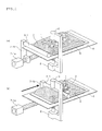
FIG. 1 is a view showing the outline of the method for removing bubbles of the present invention; -
FIG. 2 is a view showing a first embodiment of the apparatus for removing bubbles according to the present invention; -
FIG. 3 is a view showing steps ofmethod 1 in the method for removing bubbles according to the present invention; -
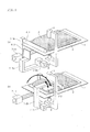
FIG. 4 is a view showing a second embodiment of the apparatus for removing bubbles according to the present invention; -
FIG. 5 is a view showing steps ofmethod 2 in the method for removing bubbles according to the present invention; -
FIG. 6 is a view showing steps of method 2' in the method for removing bubbles according to the present invention; -
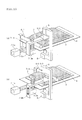
FIG. 7 is a view showing a fourth embodiment of the apparatus for removing bubbles according to the present invention; -
FIG. 8 is a view showing steps ofmethod 3 in the method for removing bubbles according to the present invention; -
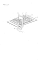
FIG. 9 is a view showing a fifth embodiment of the apparatus for removing bubbles according to the present invention; -
FIG. 10 is a view showing a sixth embodiment of the apparatus for removing bubbles according to the present invention; -
FIG. 11 is a photograph showing the results of the Examples of the present invention; -
FIG. 12 is a photograph showing a conventional culture bag observation apparatus; and -
FIG. 13 is a view showing the state in which cells are observed by means of a conventional culture bag observation apparatus. - Hereinbelow, an explanation will be made on the embodiment of the present invention.
- First, the outline of the method for removing bubbles of the present invention will be explained with reference to
FIG. 1 . - The method for removing bubbles of the present invention is a method in which, when observing the inside of a container that is made of a soft package material and encloses a liquid that contains bubbles, a part of space in the container is set to be an observation area, and the bubbles are removed outside from the observation area, wherein the bubbles are pushed outside the observation area by pressing from above a part of the upper surface of the container that is positioned above the observation area by means of a pressing member and by moving the pressing member.
- Specifically, the following three methods can be given, which may be combined.
- The
method 1 is a method in which a rod-like pressing member 6-1 is allowed to be horizontal and pressed against the upper surface of the container. Then, the rod-like pressing member 6-1 is moved in the horizontal direction to pass over an observation hole 5, i.e. over a part of the upper surface of acontainer 3 that is located above the observation area in thecontainer 3, whereby bubbles are pushed outside the observation area. - The
method 2 is a method in which, by using a plate-like pressing member 6-2 is used and pressed at an angle against a part of the upper surface of thecontainer 3 that is above the observation hole 5. By moving rotationally the plate-like pressing member 6-2 until it becomes horizontal relative to the upper surface of the container, bubbles are pushed outside the observation area. - The method 2' is a method in which, the plate-like pressing member 6-2 is used and pressed at an angle against a part of the upper surface of the
container 3 that is positioned above the observation hole 5. By swinging the plate-like pressing member 6-2 between a position where the pressing member is held at the angle and a position where the pressing member becomes horizontal with respect to the upper surface of the container, bubbles are pushed outside the observation area. - The
method 3 is a method in which a plate-like pressing member 6-3 is used horizontally, and a part of the upper surface of thecontainer 3 positioned above the observation area, that is above the observation hole 5, is pressed by means of the pressing member 6-3, whereby bubbles are pushed outside the observation area. - As mentioned above, when gases that have been dissolved in the culture liquid are generated as bubbles, small bubbles are mainly generated. Further, when gases that enter the culture bag by passing through the film from the outside foam to cause bubbles to be generated when stirring the culture liquid, relatively large bubbles may tend to be generated. In the specification of this application, small bubbles mean bubbles having a diameter of about 0.1 mm or less, and large bubbles mean bubbles having a diameter of larger than about 0.1 mm.
- Large bubbles can be efficiently removed by any of
methods - Small bubbles, in particular, those having a diameter of about several tens µm may be stuck to the inner surface of a culture bag, and is hardly moved. Normally, observation of cells is conducted by taking a microphotograph. As mentioned above, even in the case of small bubbles, it exerts a significant effect when they are enlarged since they have a larger size as compared with that of cells. When removal of bubbles is conducted by
method 1 ormethod 2, small bubbles that have not been adhered to the inner surface of a culture bag can be removed. However, small bubbles adhering to the inner surface of a culture bag are difficult to be removed. On the other hand, in the case of removal by method 2' ormethod 3, it is possible to remove small bubbles efficiently. Further, by using them in combination, it becomes possible to remove bubbles more efficiently from the observation area. - Next, the method for removing bubbles and the constitution of the apparatus for removing bubbles according to the first embodiment of the present invention will be explained with reference to
FIG. 2 andFIG. 3 . The apparatus for removing bubbles of this embodiment can be preferably used when the method for removing bubbles of the above-mentionedmethod 1 is conducted. - That is, the apparatus for removing bubbles according to this embodiment comprises, as shown in these figures, a
container 3 in which aliquid 2 that contains bubbles 1 is enclosed, a mounting table 4 on which thiscontainer 3 is mounted, a rod-like pressing member 6-1 that presses the upper surface of thecontainer 3, and a driving unit 7-1 that allows this rod-like pressing member 6-1 to move horizontally. - No specific restrictions are imposed on the
container 3 as long as it is a bag-like container made of a soft package material and is capable of enclosing a liquid. Since the container serves to remove bubbles from the observation range by moving the bubbles in the liquid, it is preferred that the container be formed of a transparent material. Further, by using a soft package material as the material of thecontainer 3, flexibility and softness can be imparted to thecontainer 3. Therefore, by pressing thecontainer 3 by means of the pressing member, it is possible to move bubbles in thecontainer 3. - When the
container 3 is used as a container for cell culture, it is preferred that it have gas permeability that is necessary for cell culture. Further, in order to be able to confirm the contents, it is preferred that part or all of the container have transparency. As the material that satisfies such requirements, for example, polyolefin, an ethylene-vinyl acetate copolymer, a styrene-based elastomer, a polyester-based thermoplastic elastomer, a silicone-based thermoplastic elastomer, silicone rubber or the like can be mentioned. - The liquid 2 to be enclosed in the
container 3 is not particularly restricted. Any liquid is possible as long as it generates bubbles. When the method for removing bubbles of this embodiment is used in cell culture, as theliquid 2, a culture liquid of cells is used. However, in the cell culture liquid, bubbles tend to be generated easily. That is, since oxygen and carbon dioxide are dissolved in a culture liquid, they tend to be generated as bubbles easily. Further, one having gas permeability is used as the material of thecontainer 3, bubbles tend to be generated easily by gases transmitted to thecontainer 3 from outside. - The mounting table 4 is a flat table that carries the
container 3 on the upper surface thereof. The mounting table 4 has the observation hole 5 as an observation range, and a part of space in thecontainer 3 positioned above the observation range is specified as an observation area. The observation hole 5 allows an observation of the inside of thecontainer 3 therethrough by means of anobservation unit 8 or the like. The observation range of the mounting table 4 may be formed of a transparent material instead of the observation hole 5. Various configurations for fixing thecontainer 3 to the mounting table 4, such as a fixture for fixing thecontainer 3 to the mounting table 4, may be provided in the mounting table 4. - A rod-like pressing member 6-1 is a pressing member that moves on the
container 3 in the horizontal direction while pressing a part of the upper surface of thecontainer 3 from above in a configuration in which the longitudinal direction thereof becomes horizontal. No specific restrictions are imposed on the rod-like pressing member 6-1 as long as bubbles are pushed outside the observation area by such an operation. For example, as shown inFIGs. 2 and3 , it is preferable to use a roller. - That is, in these figures, the rod-like pressing member 6-1 is formed in the shape of a cylindrical form, and is arranged on the upper surface of the
container 3 such that the axial direction thereof becomes in parallel with the width direction of thecontainer 3. Due to such a configuration, the rod-like pressing member 6-1 can be moved by rotation horizontally along the longitudinal direction of thecontainer 3. The rod-like pressing member 6-1 is configured such that the length in the axial direction thereof is longer than the width of thecontainer 3. - The rod-like pressing member 6-1 passes a region above the observation hole 5, i.e. a region of the
container 3 above the observation area, while pressing the upper surface of thecontainer 3. As a result, by the movement of the rod-like pressing member 6-1, bubbles can be moved within thecontainer 3, and removed outside the observation area. - The driving unit 7-1 is a rod-like horizontal moving means that is connected to the rod-like pressing member 6-1 and allows it to move in the horizontal direction. The driving unit 7-1 is not particularly restricted as long as it can move the rod-like pressing member 6-1 in the horizontal direction while pressing from above the
container 3. For example, as shown inFIG. 2 , it can be configured such that it is provided with an electrically-operated driving part 7-1a and a supporting part 7-1 b that is connected to the rod-like pressing member 6-1 and is moved by the driving part 7-1a. - In the figure, the supporting part 7-1 b is arranged upwardly on one side of the mounting table 4, and is connected to the edge part of the rod-like pressing member 6-1 to support the rod-like pressing member 6-1. A configuration may be possible in which this supporting part 7-1 b is provided on the both sides of the mounting table 4. Further, the supporting part 7-1 b is connected to the driving part 7-1 a. By moving this supporting part 7-1 b in the horizontal direction by means of the driving part 7-1a, it is possible to allow the rod-like pressing member 6-1 connected to the supporting part 7-1 b to move horizontally at the horizontal position at which the
container 3 is pressed from above, whereby bubbles within thecontainer 3 can be moved. It is preferred that a driving part that moves the supporting part 7-1 b in the up-and-down direction be further provided in the driving apparatus 7-1, thereby to allow the horizontal position at which thecontainer 3 is pressed to be changed easily. - As such driving part, an electrically-operated cylinder (an actuator for horizontal movement or an actuator for vertical movement) can be used. Instead of the electrically-operated actuator, it is possible to use an actuator utilizing pneumatic pressure, hydraulic pressure or electromagnetic force. A configuration in which a motor or a cam is used is possible.
- In the above-mentioned example, the pressing member is moved on the
container 3. However, it is possible to configure such that thecontainer 3 is moved with the pressing member being fixed. The same can be applied to the following embodiments. - When the apparatus for removing bubbles of this embodiment is used for cell culture, it is preferred that it be provided with an
observation unit 8 for photographing cells in thecontainer 3 through the observation range (an observation hole 5 or a transparent member) provided in the mounting table 4 and alightening 9 that illuminates the observation area in thecontainer 3. - The
observation unit 8 is a microscope provided with a camera function, and cells in thecontainer 3 are automatically photographed through the observation range in a fixed time period. Further, also not shown in the figure, data of images obtained by photographing are inputted into an information processing apparatus, and the number of cells in the image is counted. As for theobservation unit 8, the automatic photographing method, and the method for counting cells, those commonly used at present can be used. The camera function may be provided separately from the microscope main body. - The
lighting 9 is provided on the side opposite to theobservation unit 8 relative to the mounting table 4. The observation area in thecontainer 3 that is positioned above the observation range of the mounting table 4 is irradiated with light, whereby light in an amount necessary for photographing by means of theobservation unit 8 is supplied. - As shown in
FIG. 3 , the method for removing bubbles of this embodiment, is a method in which bubbles in thecontainer 3 are removed by using such apparatus for removing bubbles. That is, while pressing the upper surface of thecontainer 3 by the rod-like pressing member 6-1, the rod-like pressing member 6-1 is allowed to move horizontally, whereby it is allowed to pass above the observation hole 5 of the mounting table 4. As a result, bubbles in thecontainer 3 can be removed from the observation area that is positioned above the observation hole 5 of the mounting table 4, whereby the inside of thecontainer 3 can be stably photographed by theobservation unit 8. - As mentioned above, according to the method for removing bubbles and the apparatus for removing bubbles of this embodiment, it is possible to move bubbles in the
container 3 and remove them from the observation area. As a result, in particular when bubbles are relatively large, it becomes possible to remove bubbles efficiently from the observation area. - Next, an explanation will be made on the method for removing bubbles and the apparatus for removing bubbles of the second embodiment of the invention with reference to
FIGs. 4 and5 . The apparatus for removing bubbles of this embodiment can be preferably used when the method for removing bubbles according to themethod 2 is conducted. - That is, as shown in these figures, the apparatus for removing bubbles of this embodiment is provided with the
container 3 in which theliquid 2 that contains thebubbles 1 is enclosed, the mounting table 4 on which thiscontainer 3 is mounted, a plate-like pressing member 6-2 that presses the upper surface of thecontainer 3 and a driving unit 7-2 that rotationally moves this plate-like pressing member 6-2. - As for the
container 3 and the mounting table 4, the same container and mounting table as those in the first embodiment can be used. The same can be applied to the following embodiments. - The plate-like pressing member 6-2 is an inclined pressing member that moves rotationally until it becomes horizontal relative to the horizontal surface while pressing the upper surface of the
container 3 at an angle relative to the horizontal surface. No particular restrictions are imposed on the plate-like pressing member 6-2, as long as it can remove bubbles outside the observation area. For example, in addition to a member having a rectangular horizontal surface as shown inFIGs. 4 and5 , members having various shapes can be used.FIG. 4 shows a relatively small plate-like pressing member 6-2, andFIG. 5 shows a transparent plate-like pressing member 6-2 of which the long side is longer than the width of thecontainer 3. - The plate-like pressing member 6-2 is pressed at an angle to a region of the upper surface of the
container 3 right above the observation area on such that it covers the region in the state in which it becomes horizontal. - As shown in these figures, in the state where the plate-like pressing member 6-2 is inclined relative to the horizontal surface of the
container 3, by allowing the plate-like pressing member 6-2 to move by rotation until it becomes horizontal while pressing the upper surface of thecontainer 3 by means of the plate-like pressing member 6-2, bubbles are moved upwardly in thecontainer 3 along the plate-like pressing member 6-2. As a result, bubbles can be moved outside the observation area. - The driving unit 7-2 is a plate-like member rotation movement means that is connected with the plate-like pressing member 6-2 and allows it to move by rotation. No specific restrictions are imposed on the driving unit 7-2 as long as it can press the upper surface of the
container 3 obliquely by the rotational move of the plate-like pressing member 6-2. For example, as shown inFIG. 4 , it can be a pressing member that is provided with an electrically-operated driving part 7-2a and a supporting part 7-2b that is connected to the plate-like pressing member 6-2 and is moved by means of the driving part 7-2a. - In this figure, the supporting part 7-2b is connected to the plate-like pressing member 6-2 at one end, and is connected to the driving part 7-2a at the other end through a rotating shaft. By allowing the driving part 7-2a to rotate the supporting part 7-2b, while pressing the upper surface of the
container 3 obliquely from above, the plate-like pressing member 6-2 can be rotationally moved. - As the driving part 7-2a, an electrically-operated actuator for rotational driving can be used. Instead of an electrically-operated actuator, pneumatic pressure, hydraulic pressure, electromagnetic force or the like can be used.
- When the apparatus for removing bubbles of this embodiment is used for cell culture, it is preferred that the apparatus be provided with the
same observation unit 8 and the lightening 9 as those of the first embodiment. The same can be applied to the following embodiments. - As shown in
FIG. 5 , the method for removing bubbles of this embodiment is a method in which bubbles in thecontainer 3 are removed from the observation area by using such an apparatus for removing bubbles, or the like. That is, the plate-like pressing member 6-2 is pressed at an angle against a region of the upper surface of thecontainer 3 right above the observation area, the plate-like pressing member 6-2 is allowed to move rotationally until it becomes horizontal relative to the upper surface of thecontainer 3. As a result, it is possible to remove bubbles in the container from the observation area in the observation hole 5 in the mounting table 4, whereby photographing of the inside of thecontainer 3 by theobservation unit 8 can be conducted stably. - According to the method for removing bubbles and the apparatus for removing bubbles of this embodiment, in particular when bubbles are relatively large, bubbles can be efficiently removed from the observation area.
- The method for removing bubbles and the configuration of the apparatus for removing bubbles of the third embodiment of the invention will be explained with reference to
FIG. 6 . The method for removing bubbles of this embodiment is the method 2' mentioned above. As the apparatus for removing bubbles, the same apparatus as that in the second embodiment can be used. - As shown in
FIG. 6 , in the method for removing bubbles of this embodiment, the plate-like pressing member 6-2 is pressed at an angle against a region of the upper surface of thecontainer 3 right above the observation area. Between a position at which the plate-like pressing member 6-2 is held at the angle and a position at which the pressing member 6-2 becomes horizontal relative to the upper surface of thecontainer 3 as a result of rotational movement, the plate-like pressing member is subjected to a swinging movement. At this time, the swinging is conducted such that the pressing member taps thecontainer 3 with a fine and quick operation. - The speed for subjecting the plate-like pressing member 6-2 to a swing movement is preferably about 50 mm/sec to 500 mm/sec. If the speed is slower than 50 mm/sec, bubbles are not moved sufficiently. On the other hand, if the speed is faster than 500 mm/sec, the inside of the
container 3 is vigorously stirred, and as a result, there is a concern that cells will be damaged, and a heavy load will be applied to the apparatus. - The frequency of allowing the plate-like pressing member 6-2 to swing is not particularly restricted, and can be appropriately set in accordance with the amount of bubbles generated in the
container 3. Further, it is possible to allow it to standstill for a prescribed time period every single reciprocal movement. - As mentioned above, according to the method for removing bubbles and the apparatus for removing bubbles of this embodiment, by swinging the plate-like pressing member 6-2, it is possible to move bubbles below the plate-like pressing member 6-2 to the surrounding area. Therefore, according to this embodiment, even if bubbles are small, it is possible to remove them efficiently from the observation area.
- Next, an explanation will be made on the method for removing bubbles and the configuration of the apparatus for removing bubbles of the fourth embodiment with reference to
FIGs. 7 and8 . The apparatus for removing bubbles of this embodiment can preferably be used when the method for removing bubbles of the above-mentionedmethod 3 is implemented. - That is, as shown in these figures, the apparatus for removing bubbles of this embodiment is provided with the
container 3 in which theliquid 2 containing thebubbles 1 is enclosed, the mounting table 4 on which thiscontainer 3 is mounted, the plate-like pressing member 6-3 that is pressed against the upper surface of thecontainer 3, and a driving unit 7-3 that moves this plate-like pressing member 6-3. - The plate-like pressing member 6-3 is a tapping member that is pressed against a part of the upper surface of the
container 3 horizontally, and presses the upper surface of thecontainer 3 by repeatable up-and-down movement. No specific restrictions are imposed on the plate-like pressing member 6-3 as long as it can push bubbles outside the observation area by this movement. In addition to one having a rectangular horizontal surface as shown inFIG. 7 , those having various shapes can be used. - The plate-like pressing member 6-3 is arranged above the observation hole 5 of the mounting table 4, i.e. above the observation area in the
container 3, and presses a region including a region right above the observation area on the upper surface of thecontainer 3. - The driving unit 7-3 is connected to the plate-like pressing member 6-3, and serves to allow this plate-like pressing member 6-3 to move reciprocally in the vertical direction, and is a plate-like up-and-down movement means. No particular restrictions are imposed on the driving unit 7-3 as long as it can stir the inside of the
container 3 by allowing the plate-like pressing member 6-3 to move reciprocally in the up-and-down direction. However, as shown inFIG. 6 , for example, it is possible to use one that drives a supporting part 7-3b connected to the plate-like pressing member 6-3 by means of an electrically-operated cylinder (an actuator for the movement in the vertical direction). Further, instead of the electrically-operated actuator, it is possible to use an actuator utilizing pneumatic pressure, hydraulic pressure or electromagnetic force. A configuration in which a motor or a cam is used is also possible. - In the method for removing bubbles of this embodiment, by using such an apparatus for removing bubbles or the like, bubbles can be removed from the observation area by the steps shown in
FIG. 8 . - That is, at first, the plate-like pressing member 6-3 is moved downwardly from a position above the
container 3, whereby the upper surface of thecontainer 3 above the observation hole 5 of the mounting table 4 is pressed. Subsequently, a reciprocal movement in which the plate-like pressing member 6-3 is moved upward, and then, the plate-like pressing member 6-3 is moved downward, is repeated at least one or more times. The reciprocal movement is stopped at a position where the plate-like pressing member 6-3 is moved downward. - If the plate-like pressing member 6-3 is moved downward in the state where it presses the upper surface of the
container 3, thebubbles 1 are flown from a region below the plate-like pressing member 6-3 to the surrounding area together with the liquid 2 in thecontainer 3. As a result, thebubbles 1 are removed from the observation area. Further, if the plate-like pressing member 6-3 is moved upward in the state where it presses the upper surface of thecontainer 3, theliquid 2 in the surrounding area is drawn into the observation area, whereby thebubbles 1 adhering to the inner surface of thecontainer 3 can be peeled off. - As mentioned above, according to the method for removing bubbles of this embodiment, it is possible to form a flow of a liquid through which bubbles are moved in the
container 3, and as a result, it is possible to efficiently remove small bubbles adhering to the inner surface of thecontainer 3. - The distance between the plate-like pressing member 6-3 and the bottom surface of the
container 3 when the plate-like pressing member 6-3 is moved downward from a position above thecontainer 3, or the width of the up-and-down movement of the plate-like pressing member 6-3 can be appropriately determined in accordance with the amount of the liquid 2 enclosed in thecontainer 3 or the thickness of thecontainer 3. - For example, when a 230 mm × 300 mm cell culture container is filled with 250 ml of a culture liquid, the thickness of the liquid will be about 5 mm. By allowing the distance between the plate-like pressing member 6-3 and the bottom surface of the
container 3 to be 1 mm or less and the width of the up-and-down movement of the plate-like pressing member 6-3 to be 5 mm or more, bubbles can preferably be removed. - The speed at which the plate-like pressing member 6-3 is moved reciprocally is about 50 mm/sec to 500 mm/sec. If the speed is slower than 50 mm/sec, bubbles cannot be moved sufficiently. On the other hand, if the speed is faster than 500 mm/sec, the inside of the
container 3 is vigorously stirred, and as a result, there is a concern that cells will be damaged, and a heavy load will be applied to the apparatus. - Further, the number of reciprocal movement of the plate-like pressing member 6-3 is not particularly restricted, and can be appropriately set according to the amount of bubbles generated in the
container 3. In addition, it can be brought into a standstill for a predetermined period of time at every reciprocation. - As mentioned above, according to the method for removing bubbles and the apparatus for removing bubbles of this embodiment, by allowing the plate-like pressing member 6-3 to move up and down repeatedly, it is possible to move bubbles below the plate-like pressing member 6-3 to the surrounding area. As a result, according to this embodiment, even if bubbles are small, it becomes possible to remove efficiently from the observation area.
- Next, an explanation will be made on the method for removing bubbles and the configuration of the apparatus for removing bubbles of the fifth embodiment with reference to
FIG. 9 . The apparatus for removing bubbles of this embodiment has a configuration that is a combination of the first embodiment and the second embodiment. It can be preferably used when bubbles are removed by implementing both themethod 1 and themethod 2 mentioned above. - The apparatus for removing bubbles of this embodiment is provided with the
container 3 in which theliquid 2 that contains thebubbles 1 is enclosed, the mounting table 4 on which thiscontainer 3 is mounted, the rod-like pressing member 6-1 that presses the upper surface of thecontainer 3, the driving unit 7-1 that moves this rod-like pressing member 6-1, the plate-like pressing member 6-2 that presses the upper surface of thecontainer 3 and the driving unit 7-2 that allows the plate-like pressing member 6-2 to move. As for the configuration of each of these, the same as those in the first embodiment and the second embodiment can be used. - The method for removing bubbles of this embodiment is not particularly restricted as long as it can implement both of the
method 1 and themethod 2. For example, the method can be one that comprises the following steps and uses the apparatus for removing bubbles of this embodiment. - First, the driving unit 7-1 is driven, and the rod-like pressing member 6-1 is moved in the horizontal direction, and is allowed to pass a region of the upper surface of the
container 3 right above the observation area while pressing this region. InFIG. 9 , the horizontal position of the rod-like pressing member 6-1 is adjusted in advance to a position where thecontainer 3 on the mounting table 4 is adequately pressed. By moving the rod-like pressing member 6-1 in the horizontal direction, it is possible to allow it to move while pressing thecontainer 3 from above. As a result, bubbles can be removed outside the observation area in thecontainer 3. - Next, the driving unit 7-2 is driven, and in the state where the plate-like pressing member 6-2 is held at an angle relative to the horizontal direction, a region including a region of the upper surface of the
container 3 right above the observation area is pressed from above, and the plate-like pressing member 6-2 is allowed to move rotationally until it becomes horizontal. As a result, it is possible to allow bubbles to move upward in thecontainer 3 along the bottom surface of the plate-like pressing member 6-2, whereby bubbles can be expelled from the region below the plate-like pressing member 6-2, and can be removed from the observation area in thecontainer 3. - As mentioned above, according to the method for removing bubbles and the apparatus for removing bubbles of this embodiment, after bubbles are removed from the observation area by moving the rod-like pressing member 6-1 in the horizontal direction while pressing the
container 3 by the rod-like pressing member 6-1, in the state being held at an angle with respect to the horizontal direction, the plate-like pressing member 6-2 is allowed to move rotationally while pressing thecontainer 3 from above until it becomes horizontal. As a result, even if bubbles remain in the observation area after the removal of bubbles by the rod-like pressing member 6-1, removal of remaining bubbles can be conducted by the plate-like pressing member 6-2. - Therefore, according to this embodiment, as compared with a case where each of the first embodiment and the second embodiment is conducted individually, removal of bubbles can be performed with a high degree of accuracy.
- Further, it is preferred that bubbles be removed from the observation area in the
container 3 by implementing both themethod 1 and the method 2' mentioned above by using the apparatus for removing bubbles of this embodiment. According to this method, as compared with a case where both themethod 1 and themethod 2 are implemented, small bubbles can be removed more efficiently, whereby removal of bubbles can be conducted with a higher degree of accuracy. - Next, an explanation will be made on the method for removing bubbles and the configuration of the apparatus for removing bubbles of the sixth embodiment with reference to
FIG. 10 . The apparatus for removing bubbles of this embodiment has a configuration that is a combination of the first embodiment and the fourth embodiment. It can be preferably used when bubbles are removed by implementing both themethod 1 and themethod 3 mentioned above. - The apparatus for removing bubbles of this embodiment is provided with the
container 3 in which theliquid 2 that contains thebubbles 1 is enclosed, the mounting table 4 on which thiscontainer 3 is mounted, the rod-like pressing member 6-1 that presses the upper surface of thecontainer 3, the driving unit 7-1 that moves this rod-like pressing member 6-1, the plate-like pressing member 6-3 that presses the upper surface of thecontainer 3 and the driving unit 7-3 that moves the plate-like pressing member 6-3. As for the configuration of each of these, the same as those in the first embodiment or the fourth embodiment can be used. - No specific restrictions are imposed on the method for removing bubbles of this embodiment as long as it can implement both the
method 1 and themethod 3. For example, the method can be one that comprises the following steps and uses the apparatus for removing bubbles of this embodiment. - First, as in the case of the fifth embodiment, the driving unit 7-1 is driven to allow the rod-like pressing member 6-1 to move in the horizontal direction, and is allowed to pass a region of the upper surface of the
container 3 right above the observation area while pressing this region. As a result, when small bubbles and relatively large bubbles are generated in thecontainer 3, small bubbles that are not adhering to the inner surface of thecontainer 3 and relatively large bubbles can be moved and removed outside the observation area in thecontainer 3. - Subsequently, the driving apparatus 7-3 is driven to allow the plate-like pressing member 6-3 to move in the up-and-down direction repeatedly. For example, the plate-like pressing member 6-3 is allowed to move downward to press the upper surface of the
container 3. Subsequently, in the state where the upper surface of thecontainer 3 is pressed, the plate-like pressing member 6-3 can be moved reciprocally in the up-and-down direction twice. Further, the number of reciprocal movement of the plate-like pressing member 6-3 is not particularly restricted, and can be appropriately set according to the amount of bubbles generated in thecontainer 3. It may be once or three times or more. As a result, small bubbles adhering to the inner surface of thecontainer 3 can be moved to the outside of a region below the plate-like pressing member 6-3, and can be removed outside the observation area in thecontainer 3. - As mentioned above, according to the method for removing bubbles and the apparatus for removing bubbles of this embodiment, first, bubbles that can be moved relatively easily are moved in the horizontal direction while pressing the
container 3 by means of the rod-like pressing member 6-1, thereby to remove them from the observation area. Subsequently, by allowing the plate-like pressing member 6-3 to move in the up-and-down direction while pressing thecontainer 3 by the plate-like pressing member 6-3, small bubbles that adhere to the inner surface of thecontainer 3 and cannot be moved easily can be removed from the observation area. - Accordingly, even if large bubbles and small bubbles are generated in the
container 3, they can be removed efficiently. - By using the method for removing bubbles and the apparatus for removing bubbles of the fourth embodiment, an experiment was conducted for removing bubbles from the container in which a liquid that contains bubbles is enclosed.
- As the container, a bag made of LLDPE (linear low-density polyethylene) with a dimension of 230 mm × 300 mm (film thickness: 0.1 mm) was used. As for the liquid, to 250 cc of water and 1 cc of a liquid detergent for washing dishes, 10 cc of air was mixed. The resultant was put and sealed in a container, and was allowed to foam until it looked white. The thickness of the bag after the liquid was sealed was about 5 mm.
- As the plate-like pressing member, a stainless-made member having a dimension of 40 mm × 40 mm and having a glass observation window was used. As the driving unit, an air cylinder (manufactured by Koganei Corporation) was used. Then, the plate-like pressing member was pressed until the distance between the bottom thereof and the bottom of the container became 1 mm, and moved twice in the up-and-down direction with a width of 5 mm. At this time, the speed of the up-and-down movement of the plate-like pressing member was about 100 mm/sec. The results are shown in
FIG. 11 . In this figure, the state of bubbles can be confirmed visually. - First, as shown in
FIG. 11 (a) , it can be confirmed that the soapy water in the container was foaming white, showing that bubbles are present throughout the container. -
FIG. 11 (b) shows the state of the observation area in the container before pressing. It can be confirmed that it was white turbid, and contained a large amount of bubbles. -
FIG. 11(c) shows the state where the plate-like pressing member is moved downward and presses the container. It can be confirmed that a part of bubbles in the observation area is removed, but bubbles are still present below (about 0.5 mm space) the plate-like pressing member. -
FIG. 11 (d) shows the state immediately after the single reciprocal up-and-down movement of the plate-like pressing member. It can be confirmed that a slight amount of bubbles remains. -
FIG. 11 (e) shows the state immediately after the twice reciprocal up-and-down movements of the plate-like pressing member. It can be confirmed that bubbles are removed from the observation area. - From this example, it can be understood that, according to the method for removing bubbles and the apparatus for removing bubbles of the present invention, when observing the inside of a container made of a soft package material in which a liquid containing bubbles is enclosed, by allowing a pressing member to move while pressing a region of the upper surface of the container right above the observation area, it is possible to push bubbles efficiently outside the observation area.
- It is needless to say that the present invention is not limited to the above-mentioned embodiments and the example, and various modifications are possible within the scope of the present invention.
- For example, the present invention has been conceived to solve the problems regarding cell culture. However, as is apparent from the example, the present invention is not an invention that exhibits advantageous effects only in cell culture, and can be widely used in the case where a liquid is enclosed in a container made of a soft package material and bubbles are required to be removed from a partial region of the container. Further, it is possible that, by combining the second embodiment and the fourth embodiment, a container is pressed from above by a plate-like pressing member that is held at an angle relative to the horizontal direction, and the pressing member is allowed to be horizontal by rotational movement, and then this plate-like pressing member is moved up and down. Further, it is also possible that, by combining the third embodiment and the fourth embodiment, a plate-like pressing member is subjected to a swing movement between a position at which the plate-like pressing member is held at an angle relative to the horizontal direction and a position at which the plate-like pressing member is moved by rotation until the pressing member becomes horizontal relative to the upper surface of the container, and then this plate-like pressing member is moved up and down.
- The present invention can be preferably used when an observation is conducted by automatically photographing cells when a large amount of cells is cultured by using a cell culture container. In addition, it can be preferably used when a liquid is enclosed in a container made of a soft package material and bubbles are required to be removed from a partial region of the container.
-
- 1
- Bubbles
- 2
- Liquid
- 3
- Container
- 4
- Mounting table
- 5
- Observation hole
- 6-1
- Rod-like pressing member
- 6-2
- Plate-like pressing member
- 6-3
- Plate-like pressing member
- 7-1, 7-2 and 7-3
- Driving unit
- 7-1 a, 7-2a and 7-3a
- Driving part
- 7-1 b, 7-2b and 7-3b
- Supporting part
- 8
- Observation unit
- 9
- Lightening
Claims (11)
- A method for removing bubbles, in which, when observing the inside of a container that is made of a soft package material and encloses a liquid that contains bubbles, a part of space in the container is set to be an observation area to be observed and the bubbles are removed from the observation area, wherein the bubbles are pushed outside the observation area by pressing from above a part of the upper surface of the container that is positioned above the observation area by means of a pressing member and by moving the pressing member.
- The method for removing bubbles according to claim 1, wherein the pressing member is a plate-like member, and the bubbles are pushed outside the observation area by pressing the pressing member horizontally against the part of the upper surface of the container that is positioned above the observation area and by moving the pressing member up and down repeatedly.
- The method for removing bubbles according to claim 1 or 2, wherein the pressing member is a plate-like member, and the bubbles are pushed outside the observation area by pressing the pressing member at an angle against the part of the upper surface of the container that is positioned above the observation area and by moving the pressing member until it becomes horizontal relative to the upper surface of the container.
- The method for removing bubbles according to claim 1 or 2, wherein the pressing member is a plate-like member, and the bubbles are pushed outside the observation area by pressing the pressing member at an angle against the part of the upper surface of the container that is positioned above the observation area and by swinging the pressing member between a position where the pressing member is held at the angle and a position where the pressing member is moved until it becomes horizontal relative to the upper surface of the container.
- The method for removing bubbles according to any one of claims 1 to 4, wherein one or two or more of the pressing members are used, at least one of the pressing member is a rod-like member, and the bubbles are pushed outside the observation area by pressing the pressing member(s) horizontally against the upper surface of the container and by allowing it or them to pass over the part of the upper surface of the container that is positioned above the observation area by moving it in the horizontal direction.
- A method for removing bubbles from a partial area of space in a container that is made of a soft package material and encloses a liquid that contains bubbles, wherein the bubbles are pushed outside the partial area by pressing from above a part of the upper surface of the container that is positioned above the partial area and by moving the pressing member.
- An apparatus for removing bubbles, wherein, when observing the inside of a container that is made of a soft package material and encloses a liquid that contains bubbles, the bubbles are removed from an observation area that is a part of space in the container,
the apparatus comprises:a mounting table provided with an observation range formed of a transparent member or a hole and specifies a part of space in the container that is positioned above the observation range as an observation area when the container is put on the mounting table;a pressing member that presses from above the part of the upper surface of the container that is positioned above the observation area; anda driving unit that moves the pressing member;wherein the driving unit moves the pressing member to push the bubbles outside the observation area. - The apparatus for removing bubbles according to claim 7, wherein the pressing member is a plate-like member, and the driving unit presses the pressing member horizontally against the part of the upper surface of the container that is positioned above the observation area and allows it to move up and down repeatedly, whereby the bubbles are pushed outside the observation area.
- The apparatus for removing bubbles according to claim 7 or 8, wherein the pressing member is a plate-like member, and the driving unit presses the pressing member at an angle against the part of the upper surface of the container that is positioned above the observation area and moves the pressing member until it becomes horizontal relative to the upper surface of the container, whereby the bubbles are pushed outside the observation area.
- The apparatus for removing bubbles according to claim 7 or 8, wherein the pressing member is a plate-like member, and the driving unit presses the pressing member at an angle against the part of the upper surface of the container that is positioned above the observation area and allows the pressing member to swing between a position where the pressing member is held at the angle and a position where the pressing member is moved until it becomes horizontal relative to the upper surface of the container, whereby the bubbles are pushed outside the observation area.
- The apparatus for removing bubbles according to any one of claims 7 to 10, wherein the apparatus comprises one or two or more pressing members, and at least one of the pressing members is a rod-like member, and wherein the driving unit presses the pressing member(s) horizontally against the upper surface of the container and moves the pressing member(s) in the horizontal direction to allow it or them to pass over the part of the upper surface of the container that is positioned above the observation area, whereby the bubbles are pushed outside the observation area.
Applications Claiming Priority (2)
| Application Number | Priority Date | Filing Date | Title |
|---|---|---|---|
| JP2012209956A JP6051730B2 (en) | 2012-09-24 | 2012-09-24 | Bubble removing method and bubble removing apparatus |
| PCT/JP2013/005226 WO2014045532A1 (en) | 2012-09-24 | 2013-09-04 | Bubble removal method and bubble removal device |
Publications (2)
| Publication Number | Publication Date |
|---|---|
| EP2899283A1 true EP2899283A1 (en) | 2015-07-29 |
| EP2899283A4 EP2899283A4 (en) | 2016-05-04 |
Family
ID=50340874
Family Applications (1)
| Application Number | Title | Priority Date | Filing Date |
|---|---|---|---|
| EP13839006.7A Withdrawn EP2899283A4 (en) | 2012-09-24 | 2013-09-04 | BUBBLE ELIMINATING METHOD AND DEVICE THEREOF |
Country Status (6)
| Country | Link |
|---|---|
| US (1) | US10077124B2 (en) |
| EP (1) | EP2899283A4 (en) |
| JP (1) | JP6051730B2 (en) |
| KR (1) | KR101696380B1 (en) |
| CN (2) | CN104619855B (en) |
| WO (1) | WO2014045532A1 (en) |
Families Citing this family (15)
| Publication number | Priority date | Publication date | Assignee | Title |
|---|---|---|---|---|
| FR2997703B1 (en) * | 2012-11-07 | 2016-12-30 | Biomerieux Sa | PROCESS FOR TREATING AT LEAST ONE BIOLOGICAL SAMPLE |
| US11077020B2 (en) * | 2013-05-07 | 2021-08-03 | Biosafe S.A. | Fluid processing based on inflatable bags, mixing system, and method of use thereof |
| JP6524784B2 (en) * | 2015-04-27 | 2019-06-05 | 東洋製罐グループホールディングス株式会社 | Stirring apparatus for cell culture system, and stirring method for cell culture system |
| JP6806055B2 (en) * | 2015-06-22 | 2021-01-06 | 東洋製罐グループホールディングス株式会社 | Cell culture method, cell culture jig and cell culture device |
| JP2017046649A (en) * | 2015-09-02 | 2017-03-09 | 大日本印刷株式会社 | Cell cryopreservation container |
| WO2017090760A1 (en) * | 2015-11-27 | 2017-06-01 | 株式会社京都製作所 | Culture device |
| RU2747305C2 (en) | 2016-06-17 | 2021-05-04 | Калиста, Инк. | System and method (versions) for intensifying biomass production |
| CA3048060A1 (en) | 2017-01-10 | 2018-07-19 | Calysta, Inc. | Gas-fed fermentation reactors, systems and processes utilizing a vertical flow zone |
| CN111107919B (en) | 2017-08-14 | 2021-12-21 | 凯利斯塔公司 | Gas-fed fermentation reactors, systems, and methods utilizing gas/liquid separation vessels |
| WO2019123662A1 (en) * | 2017-12-22 | 2019-06-27 | オリンパス株式会社 | Bioinstrumentation device, bioinstrumentation system, and bioinstrumentation method |
| DE102018214972A1 (en) * | 2018-09-04 | 2020-03-05 | Krones Ag | Method and device for displacing air from bottles with carbonated drinks |
| CN109626322B (en) * | 2018-12-17 | 2021-09-07 | 南通大学 | A facile preparation method and SERS application of nano-spike-shaped polymer arrays |
| JP7379824B2 (en) * | 2019-02-12 | 2023-11-15 | 東洋製罐グループホールディングス株式会社 | Liquid thickness control mechanism, culture device, and liquid thickness control method |
| US20230203422A1 (en) * | 2020-05-28 | 2023-06-29 | Toyo Seikan Group Holdings, Ltd. | System for culturing cells including removing air in cell culture bag |
| CN112026118B (en) * | 2020-09-02 | 2024-09-24 | 佛山市鹏旺机械传动设备有限公司 | Synchronous belt bubble removing equipment and using method thereof |
Family Cites Families (20)
| Publication number | Priority date | Publication date | Assignee | Title |
|---|---|---|---|---|
| US6238908B1 (en) | 1995-06-07 | 2001-05-29 | Aastrom Biosciences, Inc. | Apparatus and method for maintaining and growth biological cells |
| ATE204322T1 (en) * | 1995-06-07 | 2001-09-15 | Aastrom Biosciences Inc | DEVICE AND METHOD FOR STORING AND CULTURING BIOLOGICAL CELLS |
| US6228635B1 (en) | 1995-06-07 | 2001-05-08 | Aastrom Bioscience, Inc. | Portable cell growth cassette for use in maintaining and growing biological cells |
| US6096532A (en) | 1995-06-07 | 2000-08-01 | Aastrom Biosciences, Inc. | Processor apparatus for use in a system for maintaining and growing biological cells |
| US5985653A (en) | 1995-06-07 | 1999-11-16 | Aastrom Biosciences, Inc. | Incubator apparatus for use in a system for maintaining and growing biological cells |
| JP2004198356A (en) | 2002-12-20 | 2004-07-15 | Univ Tohoku | Method for measuring sample density and method for removing bubbles from sample surface |
| JP2005034020A (en) * | 2003-07-17 | 2005-02-10 | Gunze Ltd | Method for sowing cell and roller for sowing cell |
| JP4771433B2 (en) | 2004-02-23 | 2011-09-14 | クレシー,ウッド,フランソワ,マリ ド | Continuous culture device equipped with a mobile container capable of selecting more appropriate cell variants |
| US20070037276A1 (en) | 2004-02-23 | 2007-02-15 | Eudes Francois Marie De Crecy | Continuous culture apparatus with mobile vessel, allowing selection of fitter cell variants and producing a culture in a continuous manner |
| EP1616619A1 (en) * | 2004-07-17 | 2006-01-18 | Tecan Trading AG | Device and method to influence air bubbles in a hybridizaion chamber |
| JP4508848B2 (en) * | 2004-08-30 | 2010-07-21 | 勳 佐藤 | Foreign object detection method |
| JP4706327B2 (en) * | 2005-05-13 | 2011-06-22 | 東洋製罐株式会社 | Cell culture vessel |
| EP1970110B1 (en) * | 2005-12-28 | 2016-07-20 | Shimadzu Corporation | Gas exchange system and method of controlling pressure-diference bubble transfer |
| WO2007076865A1 (en) | 2005-12-30 | 2007-07-12 | Drugmode Aps | Bioreactor for cell and tissue culture |
| JP4803362B2 (en) * | 2006-01-26 | 2011-10-26 | 東洋製罐株式会社 | Liquid content filling and sealing method for pouch with spout and apparatus therefor |
| JP2009031173A (en) * | 2007-07-30 | 2009-02-12 | Toppan Printing Co Ltd | High precision particle measurement equipment in liquid |
| CN101157277A (en) * | 2007-10-15 | 2008-04-09 | 武汉金德涞生物科技有限公司 | Blood plasma bag air blister squeezer |
| JP5659479B2 (en) * | 2009-10-21 | 2015-01-28 | 東洋製罐グループホールディングス株式会社 | Cell counting method and cell counting apparatus in culture vessel |
| JP5722329B2 (en) | 2010-08-12 | 2015-05-20 | 株式会社日立製作所 | Automatic culture equipment |
| JP5786444B2 (en) * | 2011-05-17 | 2015-09-30 | 東洋製罐グループホールディングス株式会社 | Cell culture method and cell culture system |
-
2012
- 2012-09-24 JP JP2012209956A patent/JP6051730B2/en active Active
-
2013
- 2013-09-04 CN CN201380047084.8A patent/CN104619855B/en not_active Expired - Fee Related
- 2013-09-04 CN CN201710407769.9A patent/CN107252708A/en active Pending
- 2013-09-04 KR KR1020157003864A patent/KR101696380B1/en not_active Expired - Fee Related
- 2013-09-04 EP EP13839006.7A patent/EP2899283A4/en not_active Withdrawn
- 2013-09-04 WO PCT/JP2013/005226 patent/WO2014045532A1/en not_active Ceased
-
2015
- 2015-03-24 US US14/667,179 patent/US10077124B2/en active Active
Also Published As
| Publication number | Publication date |
|---|---|
| KR20150038073A (en) | 2015-04-08 |
| CN104619855B (en) | 2018-05-25 |
| CN107252708A (en) | 2017-10-17 |
| US10077124B2 (en) | 2018-09-18 |
| CN104619855A (en) | 2015-05-13 |
| EP2899283A4 (en) | 2016-05-04 |
| KR101696380B1 (en) | 2017-01-13 |
| JP6051730B2 (en) | 2016-12-27 |
| JP2014064476A (en) | 2014-04-17 |
| WO2014045532A1 (en) | 2014-03-27 |
| US20150191262A1 (en) | 2015-07-09 |
Similar Documents
| Publication | Publication Date | Title |
|---|---|---|
| EP2899283A1 (en) | Bubble removal method and bubble removal device | |
| KR101097541B1 (en) | Reactor | |
| US9228166B2 (en) | Rockable biocontainer | |
| JP5726146B2 (en) | Gas supply structure, foam control system, foldable bag container, bioreactor bag forming method, and article | |
| CN102348794B (en) | Cell culture method, cell culture device, method for counting objects to be counted in container, and device for counting | |
| CN111511898B (en) | Cell culture method and device | |
| US20150218501A1 (en) | Disposable bottle reactor tank | |
| JP2025081590A (en) | Fluid autosampler and incubator | |
| JP6739273B2 (en) | Single-use culture apparatus and culture method | |
| KR20180042366A (en) | Peristaltic Manifold Assembly | |
| KR20120026078A (en) | Device for cultivating cells and/or microorganisms | |
| JP7643495B2 (en) | Apparatus and method for manipulating living organisms | |
| JP2018161115A (en) | Cell culture device and cell culture method | |
| JP2015000025A (en) | Culture apparatus and culture method | |
| US20070231901A1 (en) | Microfluidic cell culture media | |
| CN117660183B (en) | Embryo microfluidic dynamic culture dish and culture method thereof | |
| JP2008501365A (en) | Generation of shear force in the reactor | |
| JP2006025767A (en) | Reaction-treating device | |
| CN114341340A (en) | Cell manufacturing device and its system | |
| JP2005304479A (en) | Treating device |
Legal Events
| Date | Code | Title | Description |
|---|---|---|---|
| PUAI | Public reference made under article 153(3) epc to a published international application that has entered the european phase |
Free format text: ORIGINAL CODE: 0009012 |
|
| 17P | Request for examination filed |
Effective date: 20150311 |
|
| AK | Designated contracting states |
Kind code of ref document: A1 Designated state(s): AL AT BE BG CH CY CZ DE DK EE ES FI FR GB GR HR HU IE IS IT LI LT LU LV MC MK MT NL NO PL PT RO RS SE SI SK SM TR |
|
| AX | Request for extension of the european patent |
Extension state: BA ME |
|
| DAX | Request for extension of the european patent (deleted) | ||
| RA4 | Supplementary search report drawn up and despatched (corrected) |
Effective date: 20160404 |
|
| RIC1 | Information provided on ipc code assigned before grant |
Ipc: C12Q 1/02 20060101AFI20160329BHEP Ipc: C12M 1/34 20060101ALI20160329BHEP Ipc: C12M 1/00 20060101ALI20160329BHEP Ipc: G01N 33/48 20060101ALI20160329BHEP |
|
| STAA | Information on the status of an ep patent application or granted ep patent |
Free format text: STATUS: EXAMINATION IS IN PROGRESS |
|
| 17Q | First examination report despatched |
Effective date: 20161123 |
|
| STAA | Information on the status of an ep patent application or granted ep patent |
Free format text: STATUS: THE APPLICATION IS DEEMED TO BE WITHDRAWN |
|
| 18D | Application deemed to be withdrawn |
Effective date: 20181219 |