EP2899160A1 - Apparatus and method for producing sio - Google Patents
Apparatus and method for producing sio Download PDFInfo
- Publication number
- EP2899160A1 EP2899160A1 EP14797591.6A EP14797591A EP2899160A1 EP 2899160 A1 EP2899160 A1 EP 2899160A1 EP 14797591 A EP14797591 A EP 14797591A EP 2899160 A1 EP2899160 A1 EP 2899160A1
- Authority
- EP
- European Patent Office
- Prior art keywords
- sio
- belt
- gas
- collecting unit
- manufacturing
- Prior art date
- Legal status (The legal status is an assumption and is not a legal conclusion. Google has not performed a legal analysis and makes no representation as to the accuracy of the status listed.)
- Granted
Links
Images



Classifications
-
- C—CHEMISTRY; METALLURGY
- C01—INORGANIC CHEMISTRY
- C01B—NON-METALLIC ELEMENTS; COMPOUNDS THEREOF; METALLOIDS OR COMPOUNDS THEREOF NOT COVERED BY SUBCLASS C01C
- C01B33/00—Silicon; Compounds thereof
- C01B33/113—Silicon oxides; Hydrates thereof
-
- B—PERFORMING OPERATIONS; TRANSPORTING
- B01—PHYSICAL OR CHEMICAL PROCESSES OR APPARATUS IN GENERAL
- B01J—CHEMICAL OR PHYSICAL PROCESSES, e.g. CATALYSIS OR COLLOID CHEMISTRY; THEIR RELEVANT APPARATUS
- B01J19/00—Chemical, physical or physico-chemical processes in general; Their relevant apparatus
- B01J19/18—Stationary reactors having moving elements inside
-
- C—CHEMISTRY; METALLURGY
- C01—INORGANIC CHEMISTRY
- C01B—NON-METALLIC ELEMENTS; COMPOUNDS THEREOF; METALLOIDS OR COMPOUNDS THEREOF NOT COVERED BY SUBCLASS C01C
- C01B33/00—Silicon; Compounds thereof
- C01B33/113—Silicon oxides; Hydrates thereof
- C01B33/12—Silica; Hydrates thereof, e.g. lepidoic silicic acid
- C01B33/18—Preparation of finely divided silica neither in sol nor in gel form; After-treatment thereof
- C01B33/181—Preparation of finely divided silica neither in sol nor in gel form; After-treatment thereof by a dry process
- C01B33/182—Preparation of finely divided silica neither in sol nor in gel form; After-treatment thereof by a dry process by reduction of a siliceous material, e.g. with a carbonaceous reducing agent and subsequent oxidation of the silicon monoxide formed
-
- C—CHEMISTRY; METALLURGY
- C23—COATING METALLIC MATERIAL; COATING MATERIAL WITH METALLIC MATERIAL; CHEMICAL SURFACE TREATMENT; DIFFUSION TREATMENT OF METALLIC MATERIAL; COATING BY VACUUM EVAPORATION, BY SPUTTERING, BY ION IMPLANTATION OR BY CHEMICAL VAPOUR DEPOSITION, IN GENERAL; INHIBITING CORROSION OF METALLIC MATERIAL OR INCRUSTATION IN GENERAL
- C23C—COATING METALLIC MATERIAL; COATING MATERIAL WITH METALLIC MATERIAL; SURFACE TREATMENT OF METALLIC MATERIAL BY DIFFUSION INTO THE SURFACE, BY CHEMICAL CONVERSION OR SUBSTITUTION; COATING BY VACUUM EVAPORATION, BY SPUTTERING, BY ION IMPLANTATION OR BY CHEMICAL VAPOUR DEPOSITION, IN GENERAL
- C23C14/00—Coating by vacuum evaporation, by sputtering or by ion implantation of the coating forming material
- C23C14/22—Coating by vacuum evaporation, by sputtering or by ion implantation of the coating forming material characterised by the process of coating
- C23C14/56—Apparatus specially adapted for continuous coating; Arrangements for maintaining the vacuum, e.g. vacuum locks
-
- C—CHEMISTRY; METALLURGY
- C23—COATING METALLIC MATERIAL; COATING MATERIAL WITH METALLIC MATERIAL; CHEMICAL SURFACE TREATMENT; DIFFUSION TREATMENT OF METALLIC MATERIAL; COATING BY VACUUM EVAPORATION, BY SPUTTERING, BY ION IMPLANTATION OR BY CHEMICAL VAPOUR DEPOSITION, IN GENERAL; INHIBITING CORROSION OF METALLIC MATERIAL OR INCRUSTATION IN GENERAL
- C23C—COATING METALLIC MATERIAL; COATING MATERIAL WITH METALLIC MATERIAL; SURFACE TREATMENT OF METALLIC MATERIAL BY DIFFUSION INTO THE SURFACE, BY CHEMICAL CONVERSION OR SUBSTITUTION; COATING BY VACUUM EVAPORATION, BY SPUTTERING, BY ION IMPLANTATION OR BY CHEMICAL VAPOUR DEPOSITION, IN GENERAL
- C23C14/00—Coating by vacuum evaporation, by sputtering or by ion implantation of the coating forming material
- C23C14/58—After-treatment
- C23C14/5873—Removal of material
-
- C—CHEMISTRY; METALLURGY
- C23—COATING METALLIC MATERIAL; COATING MATERIAL WITH METALLIC MATERIAL; CHEMICAL SURFACE TREATMENT; DIFFUSION TREATMENT OF METALLIC MATERIAL; COATING BY VACUUM EVAPORATION, BY SPUTTERING, BY ION IMPLANTATION OR BY CHEMICAL VAPOUR DEPOSITION, IN GENERAL; INHIBITING CORROSION OF METALLIC MATERIAL OR INCRUSTATION IN GENERAL
- C23C—COATING METALLIC MATERIAL; COATING MATERIAL WITH METALLIC MATERIAL; SURFACE TREATMENT OF METALLIC MATERIAL BY DIFFUSION INTO THE SURFACE, BY CHEMICAL CONVERSION OR SUBSTITUTION; COATING BY VACUUM EVAPORATION, BY SPUTTERING, BY ION IMPLANTATION OR BY CHEMICAL VAPOUR DEPOSITION, IN GENERAL
- C23C14/00—Coating by vacuum evaporation, by sputtering or by ion implantation of the coating forming material
- C23C14/22—Coating by vacuum evaporation, by sputtering or by ion implantation of the coating forming material characterised by the process of coating
- C23C14/24—Vacuum evaporation
-
- C—CHEMISTRY; METALLURGY
- C23—COATING METALLIC MATERIAL; COATING MATERIAL WITH METALLIC MATERIAL; CHEMICAL SURFACE TREATMENT; DIFFUSION TREATMENT OF METALLIC MATERIAL; COATING BY VACUUM EVAPORATION, BY SPUTTERING, BY ION IMPLANTATION OR BY CHEMICAL VAPOUR DEPOSITION, IN GENERAL; INHIBITING CORROSION OF METALLIC MATERIAL OR INCRUSTATION IN GENERAL
- C23C—COATING METALLIC MATERIAL; COATING MATERIAL WITH METALLIC MATERIAL; SURFACE TREATMENT OF METALLIC MATERIAL BY DIFFUSION INTO THE SURFACE, BY CHEMICAL CONVERSION OR SUBSTITUTION; COATING BY VACUUM EVAPORATION, BY SPUTTERING, BY ION IMPLANTATION OR BY CHEMICAL VAPOUR DEPOSITION, IN GENERAL
- C23C14/00—Coating by vacuum evaporation, by sputtering or by ion implantation of the coating forming material
- C23C14/22—Coating by vacuum evaporation, by sputtering or by ion implantation of the coating forming material characterised by the process of coating
- C23C14/56—Apparatus specially adapted for continuous coating; Arrangements for maintaining the vacuum, e.g. vacuum locks
- C23C14/562—Apparatus specially adapted for continuous coating; Arrangements for maintaining the vacuum, e.g. vacuum locks for coating elongated substrates
-
- C—CHEMISTRY; METALLURGY
- C23—COATING METALLIC MATERIAL; COATING MATERIAL WITH METALLIC MATERIAL; CHEMICAL SURFACE TREATMENT; DIFFUSION TREATMENT OF METALLIC MATERIAL; COATING BY VACUUM EVAPORATION, BY SPUTTERING, BY ION IMPLANTATION OR BY CHEMICAL VAPOUR DEPOSITION, IN GENERAL; INHIBITING CORROSION OF METALLIC MATERIAL OR INCRUSTATION IN GENERAL
- C23C—COATING METALLIC MATERIAL; COATING MATERIAL WITH METALLIC MATERIAL; SURFACE TREATMENT OF METALLIC MATERIAL BY DIFFUSION INTO THE SURFACE, BY CHEMICAL CONVERSION OR SUBSTITUTION; COATING BY VACUUM EVAPORATION, BY SPUTTERING, BY ION IMPLANTATION OR BY CHEMICAL VAPOUR DEPOSITION, IN GENERAL
- C23C14/00—Coating by vacuum evaporation, by sputtering or by ion implantation of the coating forming material
- C23C14/58—After-treatment
- C23C14/5873—Removal of material
- C23C14/588—Removal of material by mechanical treatment
Definitions
- the present disclosure relates to an apparatus and method for manufacturing silicon oxide (SiO), and more particularly, to an apparatus and method for manufacturing SiO, which may lower a manufacturing cost of SiO by collecting SiO continuously.
- SiO silicon oxide
- a secondary battery refers to a rechargeable battery
- a primary battery refers to a non-rechargeable battery.
- Secondary batteries are widely used for electronic devices such as cellular phones, notebook computers, video cameras, electric vehicles, or the like.
- a lithium secondary battery recently has a higher capacity in comparison to nickel-cadmium batteries or nickel hydrogen batteries and a high energy density per unit weight. For this reason, lithium secondary batteries are being utilized more and more.
- the lithium secondary battery includes an electrode assembly in which a cathode plate coated with a cathode active material and an anode plate coated with an anode active material are disposed with a separator interposed between them, and the electrode assembly is contained and sealed in an exterior material together with an electrolyte.
- the cathode active material generally employs lithium metal oxides such as LiMn 2 O 4 or LiCoO 2
- the anode active material generally employs a carbon material.
- a lithium metal was used in an early stage, but since lithium has low reversibility and low safety, a carbon material is widely used at present.
- the carbon material has a small volume change, excellent reversibility and good price, though its capacity is small in comparison to a lithium metal.
- lithium secondary batteries are used more and more, high-capacity lithium secondary batteries are demanded more and more, and accordingly a high-capacity anode active material capable of substituting a small-capacity carbon material is also demanded.
- a metal such as Si and Sn, which exhibits a high charging/discharging capacity in comparison to a carbon material and allows electrochemical alloying, as the anode active material.
- the metallic anode active material is easily cracked or made into powder due to its serious change of volume accompanied with charging or discharging, and thus a secondary battery using such a metallic anode active material suffers from a rapidly deteriorated capacity according to charging/discharging cycles and a short cycle span.
- SiO a metal oxide such as SiO
- SiO may be used as the anode active material solely or together with another material such as a carbon material.
- the present disclosure is designed to solve the problems of the related art, and therefore the present disclosure is directed to providing an apparatus and method for manufacturing SiO, which may effectively lower a SiO manufacturing cost by allowing SiO to be continuously manufactured.
- an apparatus for manufacturing SiO which includes a reaction unit configured to receive a SiO-making material and bring the received material into reaction by heating to generate a SiO gas; and a collecting unit configured to maintain an internal temperature lower than an internal temperature of the reaction unit, the collecting unit including a rotating member in an inner space thereof, wherein the collecting unit collects a SiO deposit by introducing the SiO gas generated by the reaction unit through an inlet formed at least at one side thereof and allowing the introduced SiO gas to be deposited to a surface of the rotating member.
- the rotating member may include a rotating body which rotates based on a central axis, and the gas introduced through the inlet may be deposited to a surface of the rotating body.
- the rotating body may have a cylindrical shape and rotate in a circumferential direction.
- the rotating member may include a belt and at least one wheel, and the gas introduced through the inlet may be deposited to a surface of the belt.
- the collecting unit may rotate the wheel to move the belt while the SiO gas is being introduced.
- At least one of the wheels may have a circular shape in a front form thereof.
- At least one of the wheels may have a polygonal shape in a front form thereof.
- At least one of the wheels may have unevenness on a surface thereof which is in contact with the belt.
- the unevenness may be formed in a rotating direction of the wheel.
- the wheel may include three or more the rotating member, and the belt may have three or more bent portions.
- the inlet may be formed in an upper portion of the collecting unit, and the rotating member may be formed so that a length direction of an upper portion of the belt is a horizontal direction.
- the collecting unit may further include a removing member for separating the SiO deposit from the surface of the rotating member.
- the removing member may be configured to have a plate form so that at least one edge thereof contacts the surface of the rotating member.
- the removing member may be inclined so that an end thereof contacting the surface of the rotating member is higher than an end opposite thereto.
- the removing member may inject a gas to the surface of the rotating member.
- the collecting unit may control the internal temperature by means of the gas injected by the removing member.
- the collecting unit may cool the surface of the rotating member by means of the gas injected by the removing member.
- the removing member may vibrate the rotating member so that the SiO deposit is easily separated from the surface of the rotating member.
- the collecting unit may maintain the internal temperature in a range of 200°C to 500°C.
- the collecting unit may maintain the inner space in a decompressed state.
- At least a part of the rotating member may be located at the inlet.
- the collecting unit may include a guide tube for guiding the SiO gas introduced through the inlet to the rotating member.
- the apparatus for manufacturing SiO according to the present disclosure may further include a supplying unit configured to store a SiO-making material and automatically supply the SiO-making material to the reaction unit.
- reaction unit may heat the supplied material to a temperature of 1200°C to 1500°C.
- a method for manufacturing SiO which includes supplying a SiO-making material to a reaction unit; bring the received material into reaction in the reaction unit by heating to generate a SiO gas; introducing the generated SiO gas to a collecting unit which maintains an internal temperature lower than an internal temperature of the reaction unit and includes a rotating member; allowing the SiO gas to be deposited to a surface of the rotating member to form a SiO deposit; and collecting the formed SiO deposit.
- the rotating member may include a rotating body which rotates based on a central axis, and in the SiO deposit forming step, the gas introduced through the inlet may be deposited to a surface of the rotating body.
- the rotating body may have a cylindrical shape and rotate in a circumferential direction.
- the rotating member may include a belt and at least one wheel, and in the SiO deposit forming step, the SiO gas may be deposited to a surface of the belt.
- the SiO gas introducing step may be performed according to a rotation of the wheel while the belt is moving.
- the collecting step may include a component for separating the SiO deposit from the surface of the rotating member.
- the SiO deposit may be separated by bringing at least one edge of the removing member having a plate form into contact with the surface of the rotating member.
- the SiO deposit may be separated by injecting a gas to the surface of the rotating member.
- the SiO deposit may be separated by vibrating the rotating member.
- the SiO deposit forming step may be performed under a temperature condition of 200°C to 500°C.
- the SiO deposit forming step may be performed under a decompressed state.
- the supplied material is heated to a temperature of 1200°C to 1500°C and brought into reaction to generate a SiO gas.
- SiO may be continuously manufactured since a SiO gas is solidified while being deposited to a surface of a rotating member and SiO may be collected in this process.
- SiO may be stably used in many fields.
- SiO may be used as an anode active material of a secondary battery or the like, and in this case, it is possible to reduce a manufacturing time and cost of the secondary battery.
- SiO may be easily separated from the surface of the rotating body by means of a removing member. Therefore, a SiO manufacturing speed may be improved.
- the removing member may separate SiO from the surface of the rotating body in a fixed location. Therefore, in this case, it is possible to prevent the apparatus or process from being complicated due to any component for moving the removing member, and SiO may be separated and collected rapidly.
- SiO may be more easily separated from the surface of the belt conveyor. Therefore, in this embodiment, a SiO manufacturing speed may be improved.
- the removing member may separate SiO from the surface of the belt conveyor in a fixed location. Therefore, in this case, it is possible to prevent the apparatus or process from being complicated due to any component for moving the belt conveyor, and SiO may be separated and collected rapidly.
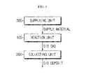
- Fig. 1 is a block diagram schematically showing a functional configuration of an apparatus for manufacturing SiO according to an embodiment of the present disclosure.
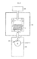
- Fig. 2 is a cross-sectional view schematically showing an apparatus for manufacturing SiO according to a first aspect of the present disclosure.
- an apparatus for manufacturing SiO according to the present disclosure includes a reaction unit 100 and a collecting unit 200.
- the reaction unit 100 has an empty space therein, and a SiO-making material is supplied to the inner space of the reaction unit 100.
- the SiO-making material S is a material used for making SiO and may include two or more substances.
- the reaction unit 100 may include silicon dioxide (SiO 2 ) serving as the SiO-making material S as well as a material for reducing the silicon dioxide into silicon oxide.
- the material for reducing silicon dioxide may include silicon-contained substances or carbon-contained substances.
- the SiO-making material S may additionally include various substances.
- the reaction unit 100 may receive the SiO-making material S in a powder form.
- the reaction unit 100 may receive silicon dioxide powder and silicon powder as the SiO-making material S.
- the present disclosure is not limited to such a specific SiO-making material S supplied to the reaction unit 100, and the SiO-making material S may also be supplied in any form other than powder.
- the reaction unit 100 brings the supplied SiO-making material S into reaction to generate a SiO (silicon oxide) gas.
- reaction unit 100 allows SiO-making materials S into reaction with each other to be chemically composed, and also allows a SiO gas to be generated through this chemical reaction.
- reaction unit 100 may give suitable conditions for the SiO-making materials to react with each other.
- the reaction unit 100 may heat materials so that the materials may actively react with each other.
- the reaction unit 100 may include a heater for heating materials.
- the reaction unit 100 may maintain a temperature of the inner space in a range of 1200°C to 1500°C by means of the heater. In this temperature range, reactivity of silicon dioxide powder and silicon powder may be particularly improved, which facilitates the generation of SiO gas.
- reaction unit 100 may maintain the inner space in an inert gas atmosphere or vacuum atmosphere for good reaction among materials.
- the reaction unit 100 may have a function of mixing the supplied materials.
- the reaction unit 100 may receive silicon dioxide powder and silicon powder, respectively, and then stir the silicon dioxide powder and the silicon powder so as to be mixed with each other.
- the reaction unit 100 may also receive a mixed powder in which the silicon dioxide powder and the silicon powder are mixed.
- the reaction unit 100 heats the mixed materials in an inert gas atmosphere or vacuum atmosphere as described above, the mixed materials may react with each other and form a SiO gas, namely SiO in a gas state.
- the formed SiO gas may move through a passage provided in the reaction unit 100 as indicated by the arrow a in Fig. 2 and be introduced to the collecting unit 200.
- the collecting unit 200 has an inner space formed therein, and an inlet I is formed at least at one side of the inner space. Therefore, the SiO gas generated in the reaction unit 100 may be introduced to the inner space of the collecting unit 200 through the inlet I. In addition, the collecting unit 200 may solidify the SiO gas introduce into the inner space to form a SiO solid.
- the collecting unit 200 includes a rotating member 210 in the inner space.
- the rotating member 210 is configured to be rotatable in the inner space of the collecting unit 200.
- the rotating member 210 may include a rotating body 211 which rotates based on a central axis O1 as shown in Fig. 2 .
- the rotating member 210 may be configured with a single rotating body 211, and in this case, the rotating body 211 may serve as the rotating member 210.
- the rotating body 210 may have a cylindrical shape.
- the rotating body 211 may be configured to rotate in a circumferential direction based on the central axis O1, as indicated by the arrow b1 in Fig. 2 .
- the collecting unit 200 includes the rotating member 210, namely the rotating body 211, in the inner space, and the SiO gas introduced into the collecting unit 200 may be deposited to a surface of the rotating body 211 and solidified, thereby changing its state into a SiO deposit.
- the collecting unit 200 may maintain its internal temperature lower than the internal temperature of the reaction unit 100.
- the collecting unit 200 may maintain the internal temperature in a range of 200°C to 500°C. In this temperature range, the SiO gas may be cooled better, and thus the SiO gas may be deposited and solidifed more effectively at the surface of the rotating body 211. In this case, the collecting unit 200 may control the inner space to have a temperature of 200°C to 500°C or control the rotating body 211 to have a surface temperature of 200°C to 500°C.
- SiO deposited to the surface of the rotating member 210, namely the rotating body 211, and solidified as described above may drop down below the rotating body 211 as the rotating body 211 rotates.
- SiO in a solid state present at the surface of the rotating body 211, namely the SiO deposit may fall down from the surface of the rotating body 211 and be collected since a gravity and a centrifugal force are applied as the rotating body 211 rotates. Therefore, the collecting unit 200 may collect the SiO deposit in this way.
- the collecting unit 200 may further include a removing member 220, as shown in Fig. 2 .
- the removing member 220 is used for separating the SiO deposit from the surface of the rotating body 211.
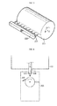
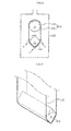
- Fig. 3 is a perspective view schematically showing the removing member 220 and the rotating body 211 according to an embodiment of the present disclosure.
- the removing member 220 may be configured to have a plate form.
- the removing member 220 having a plate form may be configured so that at least one edge thereof contacts the surface of the rotating body 211.
- the SiO deposit present at the surface of the rotating body 211 may be more easily separated from the surface of the rotating body 211 by means of the removing member 220.
- the rotating body 211 may rotate in a circumferential direction, and the removing member 220 may scrape out the SiO deposit present at or adhered to the surface of the rotating body 211 as long as the removing member 220 is fixed in contact with the surface of the rotating body 211 at a specific location.
- the edge of the removing member 220 which is in contact with the surface of the rotating body 211, may have a length capable of covering the entire width of the rotating body 211.
- the edge of the removing member 220 may have a length similar to or greater than the width of the rotating body 211.
- the removing member 220 even though the removing member 220 is fixed to a specific location, SiO deposits adhered to the entire surface of the rotating body 211 may be detached.
- the removing member 220 is configured so that its edges partially contact the surface of the rotating body 211 at a fixed location as shown in Fig. 3 , even though the removing member 220 does not move along the surface of the rotating body 211, the removing member 220 may scrape the SiO deposits adhered to the entire surface of the rotating body 211 as the rotating body 211 rotates in a circumferential direction.
- the removing member 220 may be inclined so that an end thereof contacting the surface of the rotating member 211 is higher than an end opposite thereto. For example, if a right end of the removing member 220 contacts the surface of the rotating body 211 as shown in Fig. 2 , the removing member 220 may be inclined so that its right end is located higher than the left end.
- SiO deposits scraped by the removing member 220 are not stacked on the removing member 220 but easily fall down.
- SiO deposits scraped at the right end of the removing member 220 are placed on the right end of the removing member 220, but since the top surface of the removing member 220 is inclined so that its left end is lower than the right end, the SiO deposits placed on the right end move toward the left end and eventually drop out of the removing member 220. Therefore, the SiO deposits may be automatically collected at the lower end of the collecting unit 200, and thus the SiO deposits may be more easily collected by the collecting unit 200.
- the location of the removing member 220 depicted in Figs. 2 and 3 is just an example, and the removing member 220 may be provided at various locations where SiO deposits present at the surface of the rotating body 211 may be scraped.
- Fig. 4 is a perspective view schematically showing the removing member 220 and the rotating body 211 according to another embodiment of the present disclosure.
- the removing member 220 may have a length shorter than the length of the rotating body 211 in a width direction. In this case, the removing member 220 may move in a width direction of the rotating body 211, as indicated by the arrow c. In other words, with respect to the rotating body 211 rotating in a circumferential direction (in a direction of b1), the removing member 220 may scrape SiO deposits adhered to the surface of the rotating body 211 while moving in a right and left direction (in a direction of c) in a state where its one edge contacts the surface of the rotating body 211.
- the rotating body 211 is not designed to have a great size corresponding to the width of the removing member 220, SiO deposits adhered to the entire surface of the rotating body 211 may be detached.
- Fig. 5 is a perspective view schematically showing the removing member 220 and the rotating body 211 according to another embodiment of the present disclosure.
- the removing member 220 may be implemented to inject a gas to the surface of the rotating body 211.
- the removing member 220 may include at least one injection nozzle 221 and inject a gas through the injection nozzle 221 so that the SiO deposits present at the surface of the rotating body 211 may be separated from the surface of the rotating body 211 by the pressure of the injected gas.
- the removing member 220 may inject a gas with a high pressure so that the SiO deposits adhered to the surface of the rotating body 211 may be easily detached.
- the removing member 220 may inject an inert gas so that the SiO deposit or SiO gas is not composed or converted into another form due to the injected gas.
- the removing member 220 may also be configured to be fixed at a specific location or movable in a width direction of the rotating body 211.
- the collecting unit 200 may control the internal temperature by using the gas injected by the removing member 220.
- the collecting unit 200 may inject a gas through the removing member 220 so that the SiO deposit is separated from the surface of the rotating body 211 and also the internal temperature is controlled to an appropriate temperature.
- the collecting unit 200 may maintain the internal temperature at an appropriate temperature, for example in a range of 200°C to 500°C, by injecting a cooling gas by the removing member 220. In this case, if the internal temperature drops below the appropriate temperature, the collecting unit 200 decreases the amount of an injected gas or rise the temperature of the injected gas so that the internal temperature does not drop below the appropriate temperature. On the contrary, if the internal temperature rises over the appropriate temperature, the collecting unit 200 may increase the amount of an injected gas or drop the temperature of the injected gas so that the internal temperature does not rise over the appropriate temperature.
- an appropriate temperature for example in a range of 200°C to 500°C
- the collecting unit 200 may easily separate the SiO deposit from the surface of the rotating body 211 and also maintain the internal temperature at an appropriate temperature, for example a temperature in which SiO may be easily deposited and solidified.
- the collecting unit 200 may cool the surface of the rotating body 211 by using the gas injected by the removing member 220.
- the collecting unit 200 may inject the cooling gas to the surface of the rotating body 211 so that the surface of the rotating body 211 is cooled.
- SiO since the surface temperature of the rotating body 211 is maintained low in comparison to other regions in the collecting unit 200, SiO may be deposited more easily to the surface of the rotating body 211. Therefore, in this embodiment, a SiO collection rate may be improved further.
- the removing member 220 may be configured to vibrate the rotating body 211, namely the rotating member 210.
- the rotating member 210 may be vibrated by the removing member 220, and the vibration of the rotating member 210 may detach the SiO deposit from the surface of the rotating member 210.
- the removing member 220 may further include a component for scraping the surface of the rotating member 210 as shown in Figs. 2 to 5 , in addition to the component for vibrating the rotating member 210.
- the rotating body 211 may be located at the inlet I in the collecting unit 200 through which a SiO gas is introduced.
- the SiO gas is deposited to the surface of the rotating body 211 and solidified, and thus it will be more advantageous in aspect of SiO deposition if the rotating body 211 is located at a side where the SiO gas is introduced. Therefore, the rotating body 211 may be located at the inlet of the collecting unit 200.
- the rotating body 211 is located at the inlet I of the collecting unit 200, this may mean that another article is not present between the inlet I and the rotating body 211 in the inner space of the collecting unit.
- another article may not be present in a linear path between the inlet I and the rotating body 211 in a flow direction of a fluid introduced through the inlet.
- a SiO gas introduced through the inlet may directly contact the rotating body 211 for the first time without any disturbance of another article.
- Fig. 6 is a cross-sectional view schematically showing the collecting unit 200 according to another embodiment of the present disclosure.
- the collecting unit 200 may further include a guide tube 230.
- one end of the guide tube 230 may be connected to the inlet I of the collecting unit 200, and the other end may extend near to the rotating member 210, namely the rotating body 211. Therefore, the collecting unit 200 may easily guide the SiO gas introduced through the inlet to the rotating body 211. For this reason, in this embodiment, since the SiO gas introduced to the collecting unit 200 may be directly guided to the surface of the rotating body 211 as a whole, the SiO gas may be easily deposited to the surface of the rotating body 211, which may further improve a collection rate of the SiO deposit.
- the collecting unit 200 may maintain the inner space in a decompressed state in order to facilitate deposition and solidification of the SiO gas.
- the decompressed state means a state in which the inner pressure is lower than a normal pressure, which includes a vacuum state.
- the collecting unit 200 may include at least one vacuum pump and valve.
- the apparatus for manufacturing SiO according to the present disclosure may further include a supplying unit 300, as shown in Fig. 1 .
- the supplying unit 300 stores materials required for making SiO and supplies these materials to the reaction unit 100.
- the supplying unit 300 may store silicon dioxide powder and silicon powder as the SiO-making material and supply them to the inner space of the reaction unit 100. At this time, the supplying unit 300 may mix these material powders at a suitable ratio and supply the mixed powder to the reaction unit 100.
- the SiO-making material may be automatically supplied to the reaction unit 100, which allows SiO to be made more continuously and rapidly.
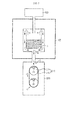
- Fig. 7 is a cross-sectional view schematically showing an apparatus for manufacturing SiO according to a second aspect of the present disclosure.
- the apparatus for manufacturing SiO according to the present disclosure includes a reaction unit 100 and a collecting unit 200.
- the reaction unit 100 has an empty space therein, and a SiO-making material S is supplied to the inner space of the reaction unit 100.
- a SiO-making material S is supplied to the inner space of the reaction unit 100.
- the description in relation to the embodiment depicted in Fig. 2 may be similarly applied, and thus the reaction unit 100 will not be described in detail here.
- the reaction unit 100 brings the supplied SiO-making material S into reaction to generate a SiO gas.
- the reaction unit 100 may give suitable conditions for the SiO-making materials to react with each other.
- the reaction unit 100 may heat materials so that the materials may actively react with each other.
- the reaction unit 100 may include a heater for heating materials.
- reaction unit 100 may maintain the inner space in an inert gas atmosphere or vacuum atmosphere for good reaction among materials.
- the reaction unit 100 may have a function of mixing the supplied materials.
- the reaction unit 100 heats the mixed materials in an inert gas atmosphere or vacuum atmosphere as described above, the mixed materials may react with each other and form a SiO gas, namely SiO in a gas state.
- the formed SiO gas may move through a passage provided in the reaction unit 100 as indicated by the arrow a in Fig. 7 and be introduced to the collecting unit 200.
- the collecting unit 200 has an inner space formed therein, and an inlet I is formed at least at one side of the inner space. Therefore, the SiO gas generated in the reaction unit 100 may be introduced to the inner space of the collecting unit 200 through the inlet I. In addition, the collecting unit 200 may solidify the SiO gas introduce into the inner space to form a SiO solid.
- the collecting unit 200 includes a rotating member 210 in the inner space, and the rotating member 210 is configured in a form of a belt conveyor in the inner space, as shown in Fig. 7 .
- the rotating member 210 includes a wheel 213 which rotates in a circumferential direction based on a central axis 02 and a belt 212 which is in contact with an outer circumference of the wheel 213 and moves in a length direction according to a rotation of the wheel 213.
- the rotating member 210 may include a plurality of wheels 213, and if the wheel 213 moves in a direction of b2, the belt 212 contacting the surface of the wheel 213 may move in a direction of c.
- the wheel 213 may be connected to a rotary shaft of a motor or the like to receive a driving force.
- the driving force may be supplied to the plurality of wheels 213 simultaneously or only to a part of the wheels 213.
- the collecting unit 200 includes the rotating member 210 in the inner space, and the SiO gas introduced into the collecting unit 200 is deposited to and solidified at the surface of the rotating member 210, particularly the surface of the belt 212, thereby changing its state into a SiO deposit.
- the collecting unit 200 may maintain its internal temperature lower than the internal temperature of the reaction unit 100.
- the collecting unit 200 may maintain the internal temperature in a range of 200°C to 500°C. In this temperature range, the SiO gas may be cooled better, and thus the SiO gas may be deposited and solidified more effectively at the surface of the belt 212. In this case, the collecting unit 200 may control the inner space to have a temperature of 200°C to 500°C or control the belt 212 to have a surface temperature of 200°C to 500°C.
- SiO deposited to the surface of the belt 212 and solidified as described above may drop down below the rotating member 210 as the rotating member 210 rotates.
- SiO in a solid state present at the surface of the belt 212 may fall down from the surface of the belt 212 due to gravity when the belt 212 is perpendicular to the ground or inclined by a predetermined angle from the ground.
- the SiO deposit present at the surface of the belt 212 may fall down from the belt 212 due to a tension applied to the belt 212, at a portion where the belt 212 comes into contact with the wheel 213 as indicated by d.
- the belt 212 moves while it partially contacts the wheel 213 when the wheel 213 rotates, and a portion of the belt 212 which is in contact with the wheel 213 may be tightly pulled.
- the SiO deposit present at the surface of the belt 212 particularly the SiO deposit solidified at the surface of the belt 212, may fall down from the belt 212 and be collected.
- the collecting unit 200 may collect the SiO deposit in this way.
- the collecting unit 200 may move the belt 212 by rotating the wheel 213 while a SiO gas is being introduced.
- the SiO gas is deposited to the surface of the belt 212 at the inlet I and is gradually solidified during its movement, and thus when reaching a location contacting the wheel 213 as indicated by d, the SiO gas may be separated from the belt 212 as a SiO deposit.
- a SiO gas may be deposited again to the surface of the belt 212 from which the SiO deposit is separated. Therefore, in this embodiment, SiO may be deposited, solidified and separated continuously and repeatedly, which facilitates continuous production of SiO and thus effectively shortens the time required for making SiO.
- the wheels 213 in the rotating member 210 may have a circular shape in its front form, as shown in Fig. 7 .
- the front side means a surface (or, a portion) not in contact with the belt 212.
- the wheel 213 may have a cylindrical shape, and in this case, the front form of the wheel 213 has a circular shape.
- the belt 212 may come into contact with a side of the wheel 213.
- the wheel 213 may come into a flat contact with the inner surface of the belt 212, and thus a tension may be regularly applied to the wheel 213. Therefore, the SiO deposit may be easily separated from the entire surface of the belt 212, and the SiO deposit does not partially remain on the surface of the belt 212 due to a portion to which a tension is not applied.
- the wheel 213 may also have another shape.
- at least one of the wheels 213 included in the rotating member 210 may have a polygonal shape in its front form.
- Fig. 8 is a front view schematically showing a collecting unit 200 according to another embodiment of the present disclosure.
- Fig. 9 is a perspective view schematically showing the wheel 213 located at a lower portion and the belt 212 contacting the wheel in the configuration of Fig. 8 .
- the belt 212 is depicted transparently in Fig. 9 .
- At least one of the wheels 213 included in the rotating member 210 may have a rectangular shape in its front form.
- the wheel 213 may have a square pillar shape.
- a greater tension is applied to the belt 212 at a portion where an edge of the wheel 213 contacts the belt 212, which may allow the belt 212 to be pulled more tightly. Therefore, in this embodiment, the SiO deposit attached to the belt 212, particularly the SiO deposit more strongly adhered to the belt 212, may be easily separated.
- the rotating member 210 may include two wheels 213, and two wheels 213 may be disposed at an upper portion and a lower portion, respectively, in the collecting unit 200.
- one of the two wheels 213 may have a cylindrical shape
- the other wheel 213 may have a square pillar shape.
- a tension is regularly applied to the entire belt 212 when the belt 212 comes in contact with the wheel 213 having a cylindrical shape, and a greater tension may be applied to a specific portion of the belt 212 when the belt 212 comes in contact with the wheel 213 having a square pillar shape. Therefore, the SiO deposit present at the surface of the belt 212 may be effectively separated from the belt 212.
- the wheel 213 having a square pillar shape may be disposed at a lower portion.
- a greater tension is applied when the belt 212 comes into contact with the wheel 213 located at a lower portion, and thus the SiO deposit present at the surface of the belt 212 may be separated from the belt 212 more when the belt 212 comes into contact with the wheel 213 located at a lower portion.
- the SiO deposit present at the surface of the belt 212 may fall down directly below the rotating member 210, the SiO deposit may be separated from the belt 212 and collected more effectively.
- Figs. 8 and 9 depicts that at least one wheel 213 has a square pillar shape
- the wheel 213 may also have various polygonal shapes in its front form, for example, a trigonal pillar, a pentagonal pillar, a hexagonal pillar or the like.
- unevenness may be formed at a surface of at least one of the wheels 213, which is in contact with the belt 212.
- Fig. 10 is a front view schematically showing a collecting unit 200 according to another embodiment of the present disclosure.
- Fig. 11 is a perspective view schematically showing a wheel 213 located at a lower portion and a belt 212 contacting the wheel in the configuration of Fig. 10 .
- the belt 212 is depicted transparently in Fig. 11 .
- unevenness may be formed at a surface of at least one of the wheels 213 in the rotating member 210, which is in contact with the belt 212.
- the belt 212 contacts a side of the wheel 213, and the unevenness may be prepared by forming a convex portion P at the side of the wheel 213.
- a stronger tension may be applied to the belt 212 at a portion where the unevenness is formed, particularly at a portion where the convex portion P is formed, and thus the SiO deposit placed on or attached to the belt 212 may effectively fall down from the belt 212.
- the unevenness may be formed in a rotating direction of the wheel 213.
- the unevenness may be prepared by disposing convex portions P at predetermined intervals along a circumferential direction of the cylindrical wheel 213.
- the convex portion P may be elongated along a side of the wheel 213.
- the convex portion P or a concave portion is identically disposed in a width direction, and thus a tension may be regularly applied over the entire width of the belt 212. Therefore, it is possible to prevent that a tension is not properly applied to a portion of the entire width of the belt 212 and thus the SiO deposit remains.
- the collecting unit 200 may further include a removing member.
- the removing member is a component capable of separating the SiO deposit from the surface of the belt 212.
- Fig. 12 is a front view schematically showing a collecting unit 200 according to another embodiment of the present disclosure.
- Fig. 13 is a perspective view schematically showing a wheel 213, a belt 212 and a removing member 220, which are located at a lower portion in the configuration of Fig. 12 .
- the removing member 220 may have a plate form.
- the removing member 220 having a plate form may be configured so that at least one edge thereof comes into contact with the surface of the belt 212.
- the SiO deposit present at the surface of the belt 212 may be more easily separated from the surface of the belt 212 by means of the removing member 220.
- the belt 212 may rotate in a length direction as indicated by an arrow, and the removing member 220 may scrape out the SiO deposit present at or adhered to the surface of the belt 212 as long as the removing member 220 is fixed in contact with the surface of the belt 212 at a specific location.
- the SiO deposit is not directly removed by the removing member 220, if a pressure is applied to the SiO deposit at the surface of the belt 212 by means of the removing member 220, the SiO deposit may be separated more easily when the belt 212 is pulled by the wheel 213.
- the edge of the removing member 220 which is in contact with the surface of the belt 212, may have a length capable of covering the entire width of the belt 212.
- the edge of the removing member 220 may have a length similar to or greater than the width of the belt 212.
- the removing member 220 even though the removing member 220 is fixed to a specific location, SiO deposits adhered to the entire surface of the belt 212 may be detached.
- the removing member 220 is configured so that its edges partially contact the surface of the belt 212 at a fixed location as shown in Figs. 12 and 13 , even though the removing member 220 does not move in a width direction, the removing member 220 may detach the SiO deposits adhered to the entire surface of the belt 212 according to the movement of the belt 212.
- the removing member 220 may have a length shorter than the length of the belt 212 in a width direction. In this case, the removing member 220 may separate SiO deposit from the entire width of the belt 212 while moving in a width direction of the belt 212.
- Fig. 14 is a perspective view schematically showing a removing member 220 according to another embodiment of the present disclosure.
- the removing member 220 may be implemented to inject a gas to the surface of the belt 212.
- the removing member 220 may include at least one injection nozzle 221 and inject a gas through the injection nozzle 221 so that the SiO deposits present at the surface of the belt 212 may be separated from the surface of the belt 212 by the pressure of the injected gas.
- the removing member 220 may inject a gas with a high pressure so that the SiO deposits adhered to the surface of the belt 212 may be easily detached.
- the removing member 220 may inject an inert gas so that the SiO deposit or SiO gas is not composed or converted into another form due to the injected gas.
- the removing member 220 may also be configured to be fixed at a specific location or movable in a width direction of the belt 212.
- the collecting unit 200 may control the internal temperature by using the gas injected by the removing member 220.
- the collecting unit 200 may inject a gas through the removing member 220 so that the SiO deposit is separated from the surface of the belt 212 and also the internal temperature is controlled to an appropriate temperature.
- the collecting unit 200 may maintain the internal temperature at an appropriate temperature, for example in a range of 200°C to 500°C, by injecting a cooling gas by the removing member 220. In this case, if the internal temperature drops below the appropriate temperature, the collecting unit 200 decreases the amount of an injected gas or rise the temperature of the injected gas so that the internal temperature does not drop below the appropriate temperature. On the contrary, if the internal temperature rises over the appropriate temperature, the collecting unit 200 may increase the amount of an injected gas or drop the temperature of the injected gas so that the internal temperature does not rise over the appropriate temperature.
- an appropriate temperature for example in a range of 200°C to 500°C
- the collecting unit 200 may easily separate the SiO deposit from the surface of the belt 212 and also maintain the internal temperature at an appropriate temperature, for example a temperature in which SiO may be easily deposited and solidified.
- the collecting unit 200 may cool the surface of the belt 212 by using the gas injected by the removing member 220.
- the collecting unit 200 may inject the cooling gas to the surface of the belt 212 so that the surface of the belt 212 is cooled.
- SiO since the surface temperature of the belt 212 is maintained low in comparison to other regions in the collecting unit 200, SiO may be deposited more easily to the surface of the belt 212. Therefore, in this embodiment, a SiO collection rate may be improved further.
- the removing member 220 may be configured to vibrate the belt 212 and/or the wheel 213.
- the rotating member 210 namely the belt 212 and/or the wheel 213, may be vibrated by the removing member 220, and the vibration of the belt 212 and/or the wheel 213 may detach the SiO deposit from the surface of the belt 212.
- the removing member 220 may further include a component for scraping the surface of the belt 212 as shown in Figs. 12 to 14 , in addition to the component for vibrating the belt 212 and/or the wheel 213.
- the rotating member 210 may be at least partially located at the inlet in the collecting unit 200.
- the SiO gas is deposited to the surface of the rotating body 211 and solidified, and thus it will be more advantageous in aspect of SiO deposition if the belt 212 is located at a side where the SiO gas is introduced. Therefore, the rotating member 210 may be at least partially located at the inlet of the collecting unit 200.
- Fig. 15 is a cross-sectional view schematically showing a collecting unit 200 according to another embodiment of the present disclosure.
- the collecting unit 200 may further include a guide tube 230.
- one end of the guide tube 230 may be connected to the inlet of the collecting unit 200, and the other end may extend near to the rotating member 210. Therefore, the collecting unit 200 may easily guide the SiO gas introduced through the inlet to the surface of the belt 212 of the rotating member 210. For this reason, in this embodiment, since the SiO gas introduced to the collecting unit 200 may be directly guided to the surface of the belt 212 as a whole, the SiO gas may be easily deposited to the surface of the belt 212, which may further improve a collection rate of the SiO deposit.
- the collecting unit 200 may maintain the inner space in a decompressed state in order to facilitate deposition and solidification of the SiO gas.
- the decompressed state means a state in which the inner pressure is lower than a normal pressure, which includes a vacuum state.
- the collecting unit 200 may include at least one vacuum pump and valve.
- the rotating member 210 may also include three or more wheels 213.
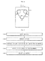
- Fig. 16 is a cross-sectional view schematically showing a collecting unit 200 according to another embodiment of the present disclosure.
- the collecting unit 200 may include a belt conveyor, namely a rotating member 210, including three or more wheel 213.
- the wheels 213 may be disposed at predetermined intervals in a length direction of the belt 212.
- the belt 212 may have a bent portion formed by each wheel 213.
- the rotating member 210 includes three wheels 213 as shown in Fig. 16
- the belt 212 may have three bent portions which configure a triangle in a length direction.
- the SiO deposit since many bent portions are formed at the belt 212, the SiO deposit may be separated more easily by means of these bent portions, which allows the SiO deposit to be collected more easily.
- the belt 212 may be disposed horizontally at the inlet I of the collecting unit 200.
- the inlet I may be located at an upper portion of the collecting unit 200 so that the SiO gas introduced into the collecting unit 200 moves downwards from the upper portion.
- the rotating member 210 may be provided so that a length direction of the upper portion of the belt 212, namely a length direction of the belt 212 with respect to a portion located at the inlet I, is a horizontal direction.
- the belt 212 and the wheel 213 may be disposed so that the length direction of the belt 212 has an inverted triangle, and in this case, a side (a line) of the triangle located in an upper portion may be disposed horizontally at the inlet I.
- the SiO gas may be introduced at the inlet I in a direction perpendicular to the length direction of the belt 212.
- the SiO gas introduced through the inlet I moves downwards and is deposited to the belt 212 placed horizontally, the SiO gas may be more easily deposited to the belt 212.
- the wheels 213 may be disposed in various patterns, without being limited to the above.
- at least a part of the wheels 213 may have a circular or polygonal front shape, and unevenness may be formed at a surface thereof which is in contact with the belt 212.
- the collecting unit 200 may further include a removing member 220.
- the apparatus for manufacturing SiO according to the present disclosure may further include a supplying unit 300, as shown in Fig. 1 .
- the supplying unit 300 stores materials required for making SiO and supplies these materials to the reaction unit 100.
- the supplying unit 300 may store silicon dioxide powder and silicon powder as the SiO-making material and supply them to the inner space of the reaction unit 100. At this time, the supplying unit 300 may mix these material powders at a suitable ratio and supply the mixed powder to the reaction unit 100.
- the SiO-making material may be automatically supplied to the reaction unit 100, which allows SiO to be made more continuously and rapidly.
- Fig. 17 is a schematic flowchart for illustrating a method for manufacturing SiO according to an embodiment of the present disclosure.
- each operation may be performed by each component of the apparatus for manufacturing SiO, described above.
- a SiO-making material is supplied to the reaction unit 100 (S110).
- the SiO-making material supplied to the reaction unit 100 may include silicon dioxide powder and silicon powder, but the present disclosure is not limited to such kinds or forms.
- the reaction unit 100 heats the supplied material and brings the material into reaction to generate a SiO gas (S120).
- Step S120 may be performed in a temperature condition of 1200°C to 1500°C.
- the generated SiO gas is introduced to the collecting unit 200 (S130).
- the collecting unit 200 maintains its internal temperature lower than the internal temperature of the reaction unit 100 and includes the rotating member 210, namely the rotating body 211 rotating based on a central axis, and/or a belt conveyor composed of the belt 212 and the wheel 213, in its inner space.
- the SiO gas is deposited to the surface of the rotating member 210, namely to the surface of the rotating body 211 or the surface of the belt 212, to form SiO deposit (S140).
- the SiO deposit formed as above is collected (S150).
- Step S130 may be performed in operation of the rotating member 210, for example while the rotating body 211 is rotating or the belt 212 is moving by the wheel 213.
- the rotating body 211 may have a cylindrical shape and rotate in a circumferential direction.
- Step S150 may include a component for separating the SiO deposit from the surface of the rotating body 211 or the belt 212.
- the SiO deposit may be separated by bringing at least an edge of the removing member 220 having a plate form into contact with the surface of the rotating body 211 or the belt 212.
- the SiO deposit may also be separated by injecting a gas to the surface of the rotating body 211 or the belt 212.
- the SiO deposit may be detached from the surface of the rotating body 211 or the belt 212 by vibrating the rotating member 210.
- Step S140 may be performed under a temperature condition where the collecting unit 200 has an internal temperature of 200°C to 500°C.
Landscapes
- Chemical & Material Sciences (AREA)
- Organic Chemistry (AREA)
- Inorganic Chemistry (AREA)
- Chemical Kinetics & Catalysis (AREA)
- Engineering & Computer Science (AREA)
- Materials Engineering (AREA)
- Mechanical Engineering (AREA)
- Metallurgy (AREA)
- Silicon Compounds (AREA)
Abstract
Description
- The present disclosure relates to an apparatus and method for manufacturing silicon oxide (SiO), and more particularly, to an apparatus and method for manufacturing SiO, which may lower a manufacturing cost of SiO by collecting SiO continuously.
- The present application claims priority to Korean Patent Application Nos.
10-2013-0055884 10-2013-0055894 filed on May 16, 2013 - Generally, a secondary battery refers to a rechargeable battery, while a primary battery refers to a non-rechargeable battery. Secondary batteries are widely used for electronic devices such as cellular phones, notebook computers, video cameras, electric vehicles, or the like. In particular, a lithium secondary battery recently has a higher capacity in comparison to nickel-cadmium batteries or nickel hydrogen batteries and a high energy density per unit weight. For this reason, lithium secondary batteries are being utilized more and more.
- The lithium secondary battery includes an electrode assembly in which a cathode plate coated with a cathode active material and an anode plate coated with an anode active material are disposed with a separator interposed between them, and the electrode assembly is contained and sealed in an exterior material together with an electrolyte.
- The cathode active material generally employs lithium metal oxides such as LiMn2O4 or LiCoO2, and the anode active material generally employs a carbon material.
- In particular, in case of the anode active material, a lithium metal was used in an early stage, but since lithium has low reversibility and low safety, a carbon material is widely used at present. The carbon material has a small volume change, excellent reversibility and good price, though its capacity is small in comparison to a lithium metal.
- However, as lithium secondary batteries are used more and more, high-capacity lithium secondary batteries are demanded more and more, and accordingly a high-capacity anode active material capable of substituting a small-capacity carbon material is also demanded. To meet such demands, there are many attempts to use a metal such as Si and Sn, which exhibits a high charging/discharging capacity in comparison to a carbon material and allows electrochemical alloying, as the anode active material.
- However, the metallic anode active material is easily cracked or made into powder due to its serious change of volume accompanied with charging or discharging, and thus a secondary battery using such a metallic anode active material suffers from a rapidly deteriorated capacity according to charging/discharging cycles and a short cycle span.
- Therefore, to prevent such problems, there have been recently made many endeavors to use a metal oxide such as SiO as the anode active material. In particular, SiO may be used as the anode active material solely or together with another material such as a carbon material.
- However, in order to utilize SiO as the anode active material, several problems should be solved. Representatively, a manufacturing cost should be lowered by shortening a manufacturing time of SiO and allowing mass production. However, SiO manufacturing techniques proposed until now have a limit in mass-producing SiO.
- Therefore, there is needed to develop a new SiO manufacturing technique.
- The present disclosure is designed to solve the problems of the related art, and therefore the present disclosure is directed to providing an apparatus and method for manufacturing SiO, which may effectively lower a SiO manufacturing cost by allowing SiO to be continuously manufactured.
- Other objects and advantages of the present disclosure will be understood from the following descriptions and become apparent by the embodiments of the present disclosure. In addition, it is understood that the objects and advantages of the present disclosure may be implemented by components defined in the appended claims or their combinations.
- In one aspect of the present disclosure, there is provided an apparatus for manufacturing SiO, which includes a reaction unit configured to receive a SiO-making material and bring the received material into reaction by heating to generate a SiO gas; and a collecting unit configured to maintain an internal temperature lower than an internal temperature of the reaction unit, the collecting unit including a rotating member in an inner space thereof, wherein the collecting unit collects a SiO deposit by introducing the SiO gas generated by the reaction unit through an inlet formed at least at one side thereof and allowing the introduced SiO gas to be deposited to a surface of the rotating member.
- Preferably, the rotating member may include a rotating body which rotates based on a central axis, and the gas introduced through the inlet may be deposited to a surface of the rotating body.
- Also preferably, the rotating body may have a cylindrical shape and rotate in a circumferential direction.
- Also preferably, the rotating member may include a belt and at least one wheel, and the gas introduced through the inlet may be deposited to a surface of the belt.
- Preferably, the collecting unit may rotate the wheel to move the belt while the SiO gas is being introduced.
- Also preferably, at least one of the wheels may have a circular shape in a front form thereof.
- Also preferably, at least one of the wheels may have a polygonal shape in a front form thereof.
- Also preferably, at least one of the wheels may have unevenness on a surface thereof which is in contact with the belt.
- More preferably, the unevenness may be formed in a rotating direction of the wheel.
- Also preferably, the wheel may include three or more the rotating member, and the belt may have three or more bent portions.
- More preferably, the inlet may be formed in an upper portion of the collecting unit, and the rotating member may be formed so that a length direction of an upper portion of the belt is a horizontal direction.
- Also preferably, the collecting unit may further include a removing member for separating the SiO deposit from the surface of the rotating member.
- Also preferably, the removing member may be configured to have a plate form so that at least one edge thereof contacts the surface of the rotating member.
- Also preferably, the removing member may be inclined so that an end thereof contacting the surface of the rotating member is higher than an end opposite thereto.
- Also preferably, the removing member may inject a gas to the surface of the rotating member.
- Also preferably, the collecting unit may control the internal temperature by means of the gas injected by the removing member.
- Also preferably, the collecting unit may cool the surface of the rotating member by means of the gas injected by the removing member.
- Also preferably, the removing member may vibrate the rotating member so that the SiO deposit is easily separated from the surface of the rotating member.
- Also preferably, the collecting unit may maintain the internal temperature in a range of 200°C to 500°C.
- Also preferably, the collecting unit may maintain the inner space in a decompressed state.
- Also preferably, at least a part of the rotating member may be located at the inlet.
- Also preferably, the collecting unit may include a guide tube for guiding the SiO gas introduced through the inlet to the rotating member.
- Also preferably, the apparatus for manufacturing SiO according to the present disclosure may further include a supplying unit configured to store a SiO-making material and automatically supply the SiO-making material to the reaction unit.
- Also preferably, the reaction unit may heat the supplied material to a temperature of 1200°C to 1500°C.
- In another aspect of the present disclosure, there is also provided a method for manufacturing SiO, which includes supplying a SiO-making material to a reaction unit; bring the received material into reaction in the reaction unit by heating to generate a SiO gas; introducing the generated SiO gas to a collecting unit which maintains an internal temperature lower than an internal temperature of the reaction unit and includes a rotating member; allowing the SiO gas to be deposited to a surface of the rotating member to form a SiO deposit; and collecting the formed SiO deposit.
- Preferably, the rotating member may include a rotating body which rotates based on a central axis, and in the SiO deposit forming step, the gas introduced through the inlet may be deposited to a surface of the rotating body.
- Also preferably, the rotating body may have a cylindrical shape and rotate in a circumferential direction.
- Also preferably, the rotating member may include a belt and at least one wheel, and in the SiO deposit forming step, the SiO gas may be deposited to a surface of the belt.
- Also preferably, the SiO gas introducing step may be performed according to a rotation of the wheel while the belt is moving.
- Also preferably, the collecting step may include a component for separating the SiO deposit from the surface of the rotating member.
- Also preferably, the SiO deposit may be separated by bringing at least one edge of the removing member having a plate form into contact with the surface of the rotating member.
- Also preferably, the SiO deposit may be separated by injecting a gas to the surface of the rotating member.
- Also preferably, the SiO deposit may be separated by vibrating the rotating member.
- Also preferably, the SiO deposit forming step may be performed under a temperature condition of 200°C to 500°C.
- Also preferably, the SiO deposit forming step may be performed under a decompressed state.
- Also preferably, in the SiO gas generating step, the supplied material is heated to a temperature of 1200°C to 1500°C and brought into reaction to generate a SiO gas.
- According to the present disclosure, SiO may be continuously manufactured since a SiO gas is solidified while being deposited to a surface of a rotating member and SiO may be collected in this process.
- Therefore, according to the present disclosure, it is possible to shorten a SiO manufacturing time, reduce a SiO manufacturing cost and allow mass production of SiO. Therefore, since a unit price of SiO is lowered and SiO may be sufficiently supplied, SiO may be stably used in many fields. In particular, SiO may be used as an anode active material of a secondary battery or the like, and in this case, it is possible to reduce a manufacturing time and cost of the secondary battery.
- In addition, in an aspect of the present disclosure, SiO may be easily separated from the surface of the rotating body by means of a removing member. Therefore, a SiO manufacturing speed may be improved.
- Further, in this aspect, the removing member may separate SiO from the surface of the rotating body in a fixed location. Therefore, in this case, it is possible to prevent the apparatus or process from being complicated due to any component for moving the removing member, and SiO may be separated and collected rapidly.
- In addition, in an aspect of the present disclosure, since a tension is applied to a belt at a portion where the belt is bent by a wheel, SiO adhered to the belt may be easily separated.
- Moreover, if the removing member is further provided, SiO may be more easily separated from the surface of the belt conveyor. Therefore, in this embodiment, a SiO manufacturing speed may be improved.
- Further, in this embodiment, the the removing member may separate SiO from the surface of the belt conveyor in a fixed location. Therefore, in this case, it is possible to prevent the apparatus or process from being complicated due to any component for moving the belt conveyor, and SiO may be separated and collected rapidly.
- The accompanying drawings illustrate preferred embodiments of the present disclosure and, together with the foregoing disclosure, serve to provide further understanding of the technical spirit of the present disclosure. However, the present disclosure is not to be construed as being limited to the drawings.
-
Fig. 1 is a block diagram schematically showing a functional configuration of an apparatus for manufacturing SiO according to an embodiment of the present disclosure. -
Fig. 2 is a cross-sectional view schematically showing an apparatus for manufacturing SiO according to a first aspect of the present disclosure. -
Fig. 3 is a perspective view schematically showing a removing member and a rotating member according to an embodiment of the present disclosure. -
Fig. 4 is a perspective view schematically showing a removing member and a rotating member according to another embodiment of the present disclosure. -
Fig. 5 is a perspective view schematically showing a removing member and a rotating member according to another embodiment of the present disclosure. -
Fig. 6 is a cross-sectional view schematically showing a collecting unit according to another embodiment of the present disclosure. -
Fig. 7 is a cross-sectional view schematically showing an apparatus for manufacturing SiO according to a second aspect of the present disclosure. -
Fig. 8 is a front view schematically showing a collecting unit according to another embodiment of the present disclosure. -
Fig. 9 is a perspective view schematically showing a wheel located at a lower portion and a belt contacting the wheel in the configuration ofFig. 8 . -
Fig. 10 is a front view schematically showing a collecting unit according to another embodiment of the present disclosure. -
Fig. 11 is a perspective view schematically showing a wheel located at a lower portion and a belt contacting the wheel in the configuration ofFig. 10 . -
Fig. 12 is a front view schematically showing a collecting unit according to another embodiment of the present disclosure. -
Fig. 13 is a perspective view schematically showing a wheel, a belt and a removing member, which are located at a lower portion in the configuration ofFig. 12 . -
Fig. 14 is a perspective view schematically showing a removing member according to another embodiment of the present disclosure. -
Fig. 15 is a cross-sectional view schematically showing a collecting unit according to another embodiment of the present disclosure. -
Fig. 16 is a cross-sectional view schematically showing a collecting unit according to another embodiment of the present disclosure. -
Fig. 17 is a schematic flowchart for illustrating a method for manufacturing SiO according to an embodiment of the present disclosure. - Hereinafter, preferred embodiments of the present disclosure will be described in detail with reference to the accompanying drawings. Prior to the description, it should be understood that the terms used in the specification and the appended claims should not be construed as limited to general and dictionary meanings, but interpreted based on the meanings and concepts corresponding to technical aspects of the present disclosure on the basis of the principle that the inventor is allowed to define terms appropriately for the best explanation.
- Therefore, the description proposed herein is just a preferable example for the purpose of illustrations only, not intended to limit the scope of the disclosure, so it should be understood that other equivalents and modifications could be made thereto without departing from the spirit and scope of the disclosure.
-
Fig. 1 is a block diagram schematically showing a functional configuration of an apparatus for manufacturing SiO according to an embodiment of the present disclosure. In addition,Fig. 2 is a cross-sectional view schematically showing an apparatus for manufacturing SiO according to a first aspect of the present disclosure. - Referring to
Figs. 1 and2 , an apparatus for manufacturing SiO according to the present disclosure includes areaction unit 100 and acollecting unit 200. - The
reaction unit 100 has an empty space therein, and a SiO-making material is supplied to the inner space of thereaction unit 100. Here, the SiO-making material S is a material used for making SiO and may include two or more substances. For example, thereaction unit 100 may include silicon dioxide (SiO2) serving as the SiO-making material S as well as a material for reducing the silicon dioxide into silicon oxide. Here, the material for reducing silicon dioxide may include silicon-contained substances or carbon-contained substances. However, in the present disclosure, the SiO-making material S may additionally include various substances. - Meanwhile, the
reaction unit 100 may receive the SiO-making material S in a powder form. For example, thereaction unit 100 may receive silicon dioxide powder and silicon powder as the SiO-making material S. However, the present disclosure is not limited to such a specific SiO-making material S supplied to thereaction unit 100, and the SiO-making material S may also be supplied in any form other than powder. - The
reaction unit 100 brings the supplied SiO-making material S into reaction to generate a SiO (silicon oxide) gas. In other words,reaction unit 100 allows SiO-making materials S into reaction with each other to be chemically composed, and also allows a SiO gas to be generated through this chemical reaction. - For this, the
reaction unit 100 may give suitable conditions for the SiO-making materials to react with each other. - In particular, the
reaction unit 100 may heat materials so that the materials may actively react with each other. For this, thereaction unit 100 may include a heater for heating materials. Preferably, thereaction unit 100 may maintain a temperature of the inner space in a range of 1200°C to 1500°C by means of the heater. In this temperature range, reactivity of silicon dioxide powder and silicon powder may be particularly improved, which facilitates the generation of SiO gas. - In addition, the
reaction unit 100 may maintain the inner space in an inert gas atmosphere or vacuum atmosphere for good reaction among materials. - Moreover, for enhancing reactivity among materials, the
reaction unit 100 may have a function of mixing the supplied materials. For example, thereaction unit 100 may receive silicon dioxide powder and silicon powder, respectively, and then stir the silicon dioxide powder and the silicon powder so as to be mixed with each other. In addition, thereaction unit 100 may also receive a mixed powder in which the silicon dioxide powder and the silicon powder are mixed. - If the
reaction unit 100 heats the mixed materials in an inert gas atmosphere or vacuum atmosphere as described above, the mixed materials may react with each other and form a SiO gas, namely SiO in a gas state. In addition, the formed SiO gas may move through a passage provided in thereaction unit 100 as indicated by the arrow a inFig. 2 and be introduced to thecollecting unit 200. - The collecting
unit 200 has an inner space formed therein, and an inlet I is formed at least at one side of the inner space. Therefore, the SiO gas generated in thereaction unit 100 may be introduced to the inner space of the collectingunit 200 through the inlet I. In addition, the collectingunit 200 may solidify the SiO gas introduce into the inner space to form a SiO solid. - In particular, in the present disclosure, the collecting
unit 200 includes a rotatingmember 210 in the inner space. The rotatingmember 210 is configured to be rotatable in the inner space of the collectingunit 200. - Preferably, the rotating
member 210 may include arotating body 211 which rotates based on a central axis O1 as shown inFig. 2 . In particular, the rotatingmember 210 may be configured with a singlerotating body 211, and in this case, therotating body 211 may serve as the rotatingmember 210. - Preferably, the
rotating body 210 may have a cylindrical shape. In this case, therotating body 211 may be configured to rotate in a circumferential direction based on the central axis O1, as indicated by the arrow b1 inFig. 2 . - As described above, the collecting
unit 200 includes the rotatingmember 210, namely therotating body 211, in the inner space, and the SiO gas introduced into the collectingunit 200 may be deposited to a surface of therotating body 211 and solidified, thereby changing its state into a SiO deposit. - In order to allow the SiO gas to be easily deposited to the surface of the
rotating body 211 and solidified, the collectingunit 200 may maintain its internal temperature lower than the internal temperature of thereaction unit 100. - For example, the collecting
unit 200 may maintain the internal temperature in a range of 200°C to 500°C. In this temperature range, the SiO gas may be cooled better, and thus the SiO gas may be deposited and solidifed more effectively at the surface of therotating body 211. In this case, the collectingunit 200 may control the inner space to have a temperature of 200°C to 500°C or control therotating body 211 to have a surface temperature of 200°C to 500°C. - SiO deposited to the surface of the rotating
member 210, namely therotating body 211, and solidified as described above may drop down below therotating body 211 as therotating body 211 rotates. In other words, SiO in a solid state present at the surface of therotating body 211, namely the SiO deposit, may fall down from the surface of therotating body 211 and be collected since a gravity and a centrifugal force are applied as therotating body 211 rotates. Therefore, the collectingunit 200 may collect the SiO deposit in this way. - Preferably, the collecting
unit 200 may further include a removingmember 220, as shown inFig. 2 . - The removing
member 220 is used for separating the SiO deposit from the surface of therotating body 211. -
Fig. 3 is a perspective view schematically showing the removingmember 220 and therotating body 211 according to an embodiment of the present disclosure. - As shown in
Fig. 3 , the removingmember 220 may be configured to have a plate form. In addition, the removingmember 220 having a plate form may be configured so that at least one edge thereof contacts the surface of therotating body 211. - In this embodiment, the SiO deposit present at the surface of the
rotating body 211 may be more easily separated from the surface of therotating body 211 by means of the removingmember 220. In particular, therotating body 211 may rotate in a circumferential direction, and the removingmember 220 may scrape out the SiO deposit present at or adhered to the surface of therotating body 211 as long as the removingmember 220 is fixed in contact with the surface of therotating body 211 at a specific location. - In this case, the edge of the removing
member 220, which is in contact with the surface of therotating body 211, may have a length capable of covering the entire width of therotating body 211. In other words, the edge of the removingmember 220 may have a length similar to or greater than the width of therotating body 211. - In this embodiment, even though the removing
member 220 is fixed to a specific location, SiO deposits adhered to the entire surface of therotating body 211 may be detached. In other words, if the removingmember 220 is configured so that its edges partially contact the surface of therotating body 211 at a fixed location as shown inFig. 3 , even though the removingmember 220 does not move along the surface of therotating body 211, the removingmember 220 may scrape the SiO deposits adhered to the entire surface of therotating body 211 as therotating body 211 rotates in a circumferential direction. - More preferably, the removing
member 220 may be inclined so that an end thereof contacting the surface of the rotatingmember 211 is higher than an end opposite thereto. For example, if a right end of the removingmember 220 contacts the surface of therotating body 211 as shown inFig. 2 , the removingmember 220 may be inclined so that its right end is located higher than the left end. - In this embodiment, SiO deposits scraped by the removing
member 220 are not stacked on the removingmember 220 but easily fall down. In other words, in the configuration ofFig. 2 , SiO deposits scraped at the right end of the removingmember 220 are placed on the right end of the removingmember 220, but since the top surface of the removingmember 220 is inclined so that its left end is lower than the right end, the SiO deposits placed on the right end move toward the left end and eventually drop out of the removingmember 220. Therefore, the SiO deposits may be automatically collected at the lower end of the collectingunit 200, and thus the SiO deposits may be more easily collected by the collectingunit 200. - Meanwhile, the location of the removing
member 220 depicted inFigs. 2 and3 is just an example, and the removingmember 220 may be provided at various locations where SiO deposits present at the surface of therotating body 211 may be scraped. -
Fig. 4 is a perspective view schematically showing the removingmember 220 and therotating body 211 according to another embodiment of the present disclosure. - Referring to
Fig. 4 , the removingmember 220 may have a length shorter than the length of therotating body 211 in a width direction. In this case, the removingmember 220 may move in a width direction of therotating body 211, as indicated by the arrow c. In other words, with respect to therotating body 211 rotating in a circumferential direction (in a direction of b1), the removingmember 220 may scrape SiO deposits adhered to the surface of therotating body 211 while moving in a right and left direction (in a direction of c) in a state where its one edge contacts the surface of therotating body 211. - In this embodiment, even though the
rotating body 211 is not designed to have a great size corresponding to the width of the removingmember 220, SiO deposits adhered to the entire surface of therotating body 211 may be detached. -
Fig. 5 is a perspective view schematically showing the removingmember 220 and therotating body 211 according to another embodiment of the present disclosure. - Referring to
Fig. 5 , the removingmember 220 may be implemented to inject a gas to the surface of therotating body 211. In other words, the removingmember 220 may include at least oneinjection nozzle 221 and inject a gas through theinjection nozzle 221 so that the SiO deposits present at the surface of therotating body 211 may be separated from the surface of therotating body 211 by the pressure of the injected gas. - Therefore, the removing
member 220 may inject a gas with a high pressure so that the SiO deposits adhered to the surface of therotating body 211 may be easily detached. - Here, the removing
member 220 may inject an inert gas so that the SiO deposit or SiO gas is not composed or converted into another form due to the injected gas. - Meanwhile, regarding a gas injection pattern, the removing
member 220 may also be configured to be fixed at a specific location or movable in a width direction of therotating body 211. - Also preferably, the collecting
unit 200 may control the internal temperature by using the gas injected by the removingmember 220. In other words, the collectingunit 200 may inject a gas through the removingmember 220 so that the SiO deposit is separated from the surface of therotating body 211 and also the internal temperature is controlled to an appropriate temperature. - For example, the collecting
unit 200 may maintain the internal temperature at an appropriate temperature, for example in a range of 200°C to 500°C, by injecting a cooling gas by the removingmember 220. In this case, if the internal temperature drops below the appropriate temperature, the collectingunit 200 decreases the amount of an injected gas or rise the temperature of the injected gas so that the internal temperature does not drop below the appropriate temperature. On the contrary, if the internal temperature rises over the appropriate temperature, the collectingunit 200 may increase the amount of an injected gas or drop the temperature of the injected gas so that the internal temperature does not rise over the appropriate temperature. - In this embodiment, by injecting the cooling gas by means of the removing
member 220, the collectingunit 200 may easily separate the SiO deposit from the surface of therotating body 211 and also maintain the internal temperature at an appropriate temperature, for example a temperature in which SiO may be easily deposited and solidified. - More preferably, the collecting
unit 200 may cool the surface of therotating body 211 by using the gas injected by the removingmember 220. In other words, the collectingunit 200 may inject the cooling gas to the surface of therotating body 211 so that the surface of therotating body 211 is cooled. In this case, since the surface temperature of therotating body 211 is maintained low in comparison to other regions in thecollecting unit 200, SiO may be deposited more easily to the surface of therotating body 211. Therefore, in this embodiment, a SiO collection rate may be improved further. - Also preferably, the removing
member 220 may be configured to vibrate therotating body 211, namely the rotatingmember 210. - In this embodiment of the present disclosure, the rotating
member 210 may be vibrated by the removingmember 220, and the vibration of the rotatingmember 210 may detach the SiO deposit from the surface of the rotatingmember 210. - In this case, in order to facilitate the separation of the SiO deposit and improve a separation speed, the removing
member 220 may further include a component for scraping the surface of the rotatingmember 210 as shown inFigs. 2 to 5 , in addition to the component for vibrating the rotatingmember 210. - Meanwhile, as shown in
Fig. 2 , therotating body 211 may be located at the inlet I in thecollecting unit 200 through which a SiO gas is introduced. In the present disclosure, the SiO gas is deposited to the surface of therotating body 211 and solidified, and thus it will be more advantageous in aspect of SiO deposition if therotating body 211 is located at a side where the SiO gas is introduced. Therefore, therotating body 211 may be located at the inlet of the collectingunit 200. Here, if therotating body 211 is located at the inlet I of the collectingunit 200, this may mean that another article is not present between the inlet I and therotating body 211 in the inner space of the collecting unit. In particular, another article may not be present in a linear path between the inlet I and therotating body 211 in a flow direction of a fluid introduced through the inlet. In this case, a SiO gas introduced through the inlet may directly contact therotating body 211 for the first time without any disturbance of another article. -
Fig. 6 is a cross-sectional view schematically showing the collectingunit 200 according to another embodiment of the present disclosure. - Referring to
Fig. 6 , the collectingunit 200 may further include aguide tube 230. - Here, one end of the
guide tube 230 may be connected to the inlet I of the collectingunit 200, and the other end may extend near to the rotatingmember 210, namely therotating body 211. Therefore, the collectingunit 200 may easily guide the SiO gas introduced through the inlet to therotating body 211. For this reason, in this embodiment, since the SiO gas introduced to thecollecting unit 200 may be directly guided to the surface of therotating body 211 as a whole, the SiO gas may be easily deposited to the surface of therotating body 211, which may further improve a collection rate of the SiO deposit. - Preferably, the collecting
unit 200 may maintain the inner space in a decompressed state in order to facilitate deposition and solidification of the SiO gas. Here, the decompressed state means a state in which the inner pressure is lower than a normal pressure, which includes a vacuum state. For this, the collectingunit 200 may include at least one vacuum pump and valve. - Meanwhile, the apparatus for manufacturing SiO according to the present disclosure may further include a supplying
unit 300, as shown inFig. 1 . - The supplying
unit 300 stores materials required for making SiO and supplies these materials to thereaction unit 100. For example, the supplyingunit 300 may store silicon dioxide powder and silicon powder as the SiO-making material and supply them to the inner space of thereaction unit 100. At this time, the supplyingunit 300 may mix these material powders at a suitable ratio and supply the mixed powder to thereaction unit 100. - If the apparatus for manufacturing SiO includes the supplying
unit 300 as described above, the SiO-making material may be automatically supplied to thereaction unit 100, which allows SiO to be made more continuously and rapidly. -
Fig. 7 is a cross-sectional view schematically showing an apparatus for manufacturing SiO according to a second aspect of the present disclosure. - Referring to
Figs. 1 and7 , the apparatus for manufacturing SiO according to the present disclosure includes areaction unit 100 and acollecting unit 200. - The
reaction unit 100 has an empty space therein, and a SiO-making material S is supplied to the inner space of thereaction unit 100. Regarding thereaction unit 100, the description in relation to the embodiment depicted inFig. 2 may be similarly applied, and thus thereaction unit 100 will not be described in detail here. - The
reaction unit 100 brings the supplied SiO-making material S into reaction to generate a SiO gas. For this, thereaction unit 100 may give suitable conditions for the SiO-making materials to react with each other. In particular, thereaction unit 100 may heat materials so that the materials may actively react with each other. For this, thereaction unit 100 may include a heater for heating materials. - In addition, the
reaction unit 100 may maintain the inner space in an inert gas atmosphere or vacuum atmosphere for good reaction among materials. - Moreover, for enhancing reactivity among materials, the
reaction unit 100 may have a function of mixing the supplied materials. - If the
reaction unit 100 heats the mixed materials in an inert gas atmosphere or vacuum atmosphere as described above, the mixed materials may react with each other and form a SiO gas, namely SiO in a gas state. In addition, the formed SiO gas may move through a passage provided in thereaction unit 100 as indicated by the arrow a inFig. 7 and be introduced to thecollecting unit 200. - The collecting
unit 200 has an inner space formed therein, and an inlet I is formed at least at one side of the inner space. Therefore, the SiO gas generated in thereaction unit 100 may be introduced to the inner space of the collectingunit 200 through the inlet I. In addition, the collectingunit 200 may solidify the SiO gas introduce into the inner space to form a SiO solid. - In particular, in an embodiment of the present disclosure, the collecting
unit 200 includes a rotatingmember 210 in the inner space, and the rotatingmember 210 is configured in a form of a belt conveyor in the inner space, as shown inFig. 7 . - Here, the rotating
member 210 includes awheel 213 which rotates in a circumferential direction based on acentral axis 02 and abelt 212 which is in contact with an outer circumference of thewheel 213 and moves in a length direction according to a rotation of thewheel 213. For example, referring toFig. 7 , the rotatingmember 210 may include a plurality ofwheels 213, and if thewheel 213 moves in a direction of b2, thebelt 212 contacting the surface of thewheel 213 may move in a direction of c. At this time, thewheel 213 may be connected to a rotary shaft of a motor or the like to receive a driving force. The driving force may be supplied to the plurality ofwheels 213 simultaneously or only to a part of thewheels 213. - As described above, the collecting
unit 200 includes the rotatingmember 210 in the inner space, and the SiO gas introduced into the collectingunit 200 is deposited to and solidified at the surface of the rotatingmember 210, particularly the surface of thebelt 212, thereby changing its state into a SiO deposit. - In order to allow the SiO gas to be easily deposited to the surface of the
belt 212 and solidified, the collectingunit 200 may maintain its internal temperature lower than the internal temperature of thereaction unit 100. - For example, the collecting
unit 200 may maintain the internal temperature in a range of 200°C to 500°C. In this temperature range, the SiO gas may be cooled better, and thus the SiO gas may be deposited and solidified more effectively at the surface of thebelt 212. In this case, the collectingunit 200 may control the inner space to have a temperature of 200°C to 500°C or control thebelt 212 to have a surface temperature of 200°C to 500°C. - SiO deposited to the surface of the
belt 212 and solidified as described above may drop down below the rotatingmember 210 as the rotatingmember 210 rotates. - First, SiO in a solid state present at the surface of the
belt 212, namely the SiO deposit, may fall down from the surface of thebelt 212 due to gravity when thebelt 212 is perpendicular to the ground or inclined by a predetermined angle from the ground. - Moreover, the SiO deposit present at the surface of the
belt 212 may fall down from thebelt 212 due to a tension applied to thebelt 212, at a portion where thebelt 212 comes into contact with thewheel 213 as indicated by d. In other words, thebelt 212 moves while it partially contacts thewheel 213 when thewheel 213 rotates, and a portion of thebelt 212 which is in contact with thewheel 213 may be tightly pulled. In addition, when thebelt 212 is pulled as described above, the SiO deposit present at the surface of thebelt 212, particularly the SiO deposit solidified at the surface of thebelt 212, may fall down from thebelt 212 and be collected. - Therefore, the collecting
unit 200 may collect the SiO deposit in this way. - Preferably, the collecting
unit 200 may move thebelt 212 by rotating thewheel 213 while a SiO gas is being introduced. In this case, the SiO gas is deposited to the surface of thebelt 212 at the inlet I and is gradually solidified during its movement, and thus when reaching a location contacting thewheel 213 as indicated by d, the SiO gas may be separated from thebelt 212 as a SiO deposit. In addition, a SiO gas may be deposited again to the surface of thebelt 212 from which the SiO deposit is separated. Therefore, in this embodiment, SiO may be deposited, solidified and separated continuously and repeatedly, which facilitates continuous production of SiO and thus effectively shortens the time required for making SiO. - Meanwhile, at least one of the
wheels 213 in the rotatingmember 210 may have a circular shape in its front form, as shown inFig. 7 . Here, the front side means a surface (or, a portion) not in contact with thebelt 212. For example, thewheel 213 may have a cylindrical shape, and in this case, the front form of thewheel 213 has a circular shape. In addition, thebelt 212 may come into contact with a side of thewheel 213. In this embodiment, thewheel 213 may come into a flat contact with the inner surface of thebelt 212, and thus a tension may be regularly applied to thewheel 213. Therefore, the SiO deposit may be easily separated from the entire surface of thebelt 212, and the SiO deposit does not partially remain on the surface of thebelt 212 due to a portion to which a tension is not applied. - However, the present disclosure is not limited to this embodiment, and the
wheel 213 may also have another shape. In particular, at least one of thewheels 213 included in the rotatingmember 210 may have a polygonal shape in its front form. -
Fig. 8 is a front view schematically showing acollecting unit 200 according to another embodiment of the present disclosure. In addition,Fig. 9 is a perspective view schematically showing thewheel 213 located at a lower portion and thebelt 212 contacting the wheel in the configuration ofFig. 8 . However, for convenience, thebelt 212 is depicted transparently inFig. 9 . - Referring to
Figs. 8 and 9 , at least one of thewheels 213 included in the rotatingmember 210 may have a rectangular shape in its front form. In other words, thewheel 213 may have a square pillar shape. In this configuration, as indicated by e in the figures, a greater tension is applied to thebelt 212 at a portion where an edge of thewheel 213 contacts thebelt 212, which may allow thebelt 212 to be pulled more tightly. Therefore, in this embodiment, the SiO deposit attached to thebelt 212, particularly the SiO deposit more strongly adhered to thebelt 212, may be easily separated. - Further, the rotating
member 210 may include twowheels 213, and twowheels 213 may be disposed at an upper portion and a lower portion, respectively, in thecollecting unit 200. In this case, as shown inFig. 8 , one of the twowheels 213 may have a cylindrical shape, and theother wheel 213 may have a square pillar shape. In this embodiment, since the twowheels 213 have different shapes, a tension is regularly applied to theentire belt 212 when thebelt 212 comes in contact with thewheel 213 having a cylindrical shape, and a greater tension may be applied to a specific portion of thebelt 212 when thebelt 212 comes in contact with thewheel 213 having a square pillar shape. Therefore, the SiO deposit present at the surface of thebelt 212 may be effectively separated from thebelt 212. - In particular, if one
wheel 213 has a square pillar shape as described above, thewheel 213 having a square pillar shape may be disposed at a lower portion. In this case, a greater tension is applied when thebelt 212 comes into contact with thewheel 213 located at a lower portion, and thus the SiO deposit present at the surface of thebelt 212 may be separated from thebelt 212 more when thebelt 212 comes into contact with thewheel 213 located at a lower portion. In this embodiment, since the SiO deposit present at the surface of thebelt 212 may fall down directly below the rotatingmember 210, the SiO deposit may be separated from thebelt 212 and collected more effectively. - Meanwhile, even though
Figs. 8 and 9 depicts that at least onewheel 213 has a square pillar shape, thewheel 213 may also have various polygonal shapes in its front form, for example, a trigonal pillar, a pentagonal pillar, a hexagonal pillar or the like. - Also preferably, unevenness may be formed at a surface of at least one of the
wheels 213, which is in contact with thebelt 212. -
Fig. 10 is a front view schematically showing acollecting unit 200 according to another embodiment of the present disclosure. In addition,Fig. 11 is a perspective view schematically showing awheel 213 located at a lower portion and abelt 212 contacting the wheel in the configuration ofFig. 10 . However, for convenience, thebelt 212 is depicted transparently inFig. 11 . - Referring to
Figs. 10 and 11 , unevenness may be formed at a surface of at least one of thewheels 213 in the rotatingmember 210, which is in contact with thebelt 212. For example, as shown in the figures, when thewheel 213 has a cylindrical shape in which a front surface and a rear surface are circular, thebelt 212 contacts a side of thewheel 213, and the unevenness may be prepared by forming a convex portion P at the side of thewheel 213. - In this embodiment, a stronger tension may be applied to the
belt 212 at a portion where the unevenness is formed, particularly at a portion where the convex portion P is formed, and thus the SiO deposit placed on or attached to thebelt 212 may effectively fall down from thebelt 212. - More preferably, the unevenness may be formed in a rotating direction of the
wheel 213. For example, as shown inFig. 11 , the unevenness may be prepared by disposing convex portions P at predetermined intervals along a circumferential direction of thecylindrical wheel 213. In addition, the convex portion P may be elongated along a side of thewheel 213. In this embodiment, when thebelt 212 moves in a length direction, the convex portion P or a concave portion is identically disposed in a width direction, and thus a tension may be regularly applied over the entire width of thebelt 212. Therefore, it is possible to prevent that a tension is not properly applied to a portion of the entire width of thebelt 212 and thus the SiO deposit remains. - Also preferably, the collecting
unit 200 may further include a removing member. The removing member is a component capable of separating the SiO deposit from the surface of thebelt 212. -
Fig. 12 is a front view schematically showing acollecting unit 200 according to another embodiment of the present disclosure. In addition,Fig. 13 is a perspective view schematically showing awheel 213, abelt 212 and a removingmember 220, which are located at a lower portion in the configuration ofFig. 12 . - Referring to
Figs. 12 and 13 , the removingmember 220 may have a plate form. In addition, the removingmember 220 having a plate form may be configured so that at least one edge thereof comes into contact with the surface of thebelt 212. - In this embodiment, the SiO deposit present at the surface of the
belt 212 may be more easily separated from the surface of thebelt 212 by means of the removingmember 220. In particular, thebelt 212 may rotate in a length direction as indicated by an arrow, and the removingmember 220 may scrape out the SiO deposit present at or adhered to the surface of thebelt 212 as long as the removingmember 220 is fixed in contact with the surface of thebelt 212 at a specific location. Moreover, even though the SiO deposit is not directly removed by the removingmember 220, if a pressure is applied to the SiO deposit at the surface of thebelt 212 by means of the removingmember 220, the SiO deposit may be separated more easily when thebelt 212 is pulled by thewheel 213. - More preferably, the edge of the removing
member 220, which is in contact with the surface of thebelt 212, may have a length capable of covering the entire width of thebelt 212. In other words, the edge of the removingmember 220 may have a length similar to or greater than the width of thebelt 212. - In this embodiment, even though the removing
member 220 is fixed to a specific location, SiO deposits adhered to the entire surface of thebelt 212 may be detached. In other words, if the removingmember 220 is configured so that its edges partially contact the surface of thebelt 212 at a fixed location as shown inFigs. 12 and 13 , even though the removingmember 220 does not move in a width direction, the removingmember 220 may detach the SiO deposits adhered to the entire surface of thebelt 212 according to the movement of thebelt 212. - Meanwhile, the removing
member 220 may have a length shorter than the length of thebelt 212 in a width direction. In this case, the removingmember 220 may separate SiO deposit from the entire width of thebelt 212 while moving in a width direction of thebelt 212. -
Fig. 14 is a perspective view schematically showing a removingmember 220 according to another embodiment of the present disclosure. - Referring to
Fig. 14 , the removingmember 220 may be implemented to inject a gas to the surface of thebelt 212. In this case, the removingmember 220 may include at least oneinjection nozzle 221 and inject a gas through theinjection nozzle 221 so that the SiO deposits present at the surface of thebelt 212 may be separated from the surface of thebelt 212 by the pressure of the injected gas. - Therefore, the removing
member 220 may inject a gas with a high pressure so that the SiO deposits adhered to the surface of thebelt 212 may be easily detached. - Here, the removing
member 220 may inject an inert gas so that the SiO deposit or SiO gas is not composed or converted into another form due to the injected gas. - Meanwhile, regarding a gas injection pattern, the removing
member 220 may also be configured to be fixed at a specific location or movable in a width direction of thebelt 212. - Also preferably, the collecting
unit 200 may control the internal temperature by using the gas injected by the removingmember 220. In other words, the collectingunit 200 may inject a gas through the removingmember 220 so that the SiO deposit is separated from the surface of thebelt 212 and also the internal temperature is controlled to an appropriate temperature. - For example, the collecting
unit 200 may maintain the internal temperature at an appropriate temperature, for example in a range of 200°C to 500°C, by injecting a cooling gas by the removingmember 220. In this case, if the internal temperature drops below the appropriate temperature, the collectingunit 200 decreases the amount of an injected gas or rise the temperature of the injected gas so that the internal temperature does not drop below the appropriate temperature. On the contrary, if the internal temperature rises over the appropriate temperature, the collectingunit 200 may increase the amount of an injected gas or drop the temperature of the injected gas so that the internal temperature does not rise over the appropriate temperature. - In this embodiment, by injecting the cooling gas by means of the removing
member 220, the collectingunit 200 may easily separate the SiO deposit from the surface of thebelt 212 and also maintain the internal temperature at an appropriate temperature, for example a temperature in which SiO may be easily deposited and solidified. - More preferably, the collecting
unit 200 may cool the surface of thebelt 212 by using the gas injected by the removingmember 220. In other words, the collectingunit 200 may inject the cooling gas to the surface of thebelt 212 so that the surface of thebelt 212 is cooled. In this case, since the surface temperature of thebelt 212 is maintained low in comparison to other regions in thecollecting unit 200, SiO may be deposited more easily to the surface of thebelt 212. Therefore, in this embodiment, a SiO collection rate may be improved further. - Also preferably, the removing
member 220 may be configured to vibrate thebelt 212 and/or thewheel 213. - In this embodiment of the present disclosure, the rotating
member 210, namely thebelt 212 and/or thewheel 213, may be vibrated by the removingmember 220, and the vibration of thebelt 212 and/or thewheel 213 may detach the SiO deposit from the surface of thebelt 212. - In this case, in order to facilitate the separation of the SiO deposit and improve a separation speed, the removing
member 220 may further include a component for scraping the surface of thebelt 212 as shown inFigs. 12 to 14 , in addition to the component for vibrating thebelt 212 and/or thewheel 213. - Meanwhile, as shown in various figures, the rotating
member 210 may be at least partially located at the inlet in thecollecting unit 200. In the present disclosure, the SiO gas is deposited to the surface of therotating body 211 and solidified, and thus it will be more advantageous in aspect of SiO deposition if thebelt 212 is located at a side where the SiO gas is introduced. Therefore, the rotatingmember 210 may be at least partially located at the inlet of the collectingunit 200. -
Fig. 15 is a cross-sectional view schematically showing acollecting unit 200 according to another embodiment of the present disclosure. - Referring to
Fig. 15 , the collectingunit 200 may further include aguide tube 230. - Here, one end of the
guide tube 230 may be connected to the inlet of the collectingunit 200, and the other end may extend near to the rotatingmember 210. Therefore, the collectingunit 200 may easily guide the SiO gas introduced through the inlet to the surface of thebelt 212 of the rotatingmember 210. For this reason, in this embodiment, since the SiO gas introduced to thecollecting unit 200 may be directly guided to the surface of thebelt 212 as a whole, the SiO gas may be easily deposited to the surface of thebelt 212, which may further improve a collection rate of the SiO deposit. - Preferably, the collecting
unit 200 may maintain the inner space in a decompressed state in order to facilitate deposition and solidification of the SiO gas. Here, the decompressed state means a state in which the inner pressure is lower than a normal pressure, which includes a vacuum state. For this, the collectingunit 200 may include at least one vacuum pump and valve. - Meanwhile, even though it is depicted in various figures that the rotating
member 210 includes twowheels 213, the rotatingmember 210 may also include three ormore wheels 213. -
Fig. 16 is a cross-sectional view schematically showing acollecting unit 200 according to another embodiment of the present disclosure. - Referring to
Fig. 16 , the collectingunit 200 may include a belt conveyor, namely a rotatingmember 210, including three ormore wheel 213. In this case, thewheels 213 may be disposed at predetermined intervals in a length direction of thebelt 212. In addition, thebelt 212 may have a bent portion formed by eachwheel 213. For example, if the rotatingmember 210 includes threewheels 213 as shown inFig. 16 , thebelt 212 may have three bent portions which configure a triangle in a length direction. In this embodiment, since many bent portions are formed at thebelt 212, the SiO deposit may be separated more easily by means of these bent portions, which allows the SiO deposit to be collected more easily. - More preferably, if the
belt 212 includes three or more bent portion, thebelt 212 may be disposed horizontally at the inlet I of the collectingunit 200. In particular, as shown inFig. 16 , the inlet I may be located at an upper portion of the collectingunit 200 so that the SiO gas introduced into the collectingunit 200 moves downwards from the upper portion. At this time, the rotatingmember 210 may be provided so that a length direction of the upper portion of thebelt 212, namely a length direction of thebelt 212 with respect to a portion located at the inlet I, is a horizontal direction. In other words, if the inlet I is located in the upper portion of the collectingunit 200, thebelt 212 and thewheel 213 may be disposed so that the length direction of thebelt 212 has an inverted triangle, and in this case, a side (a line) of the triangle located in an upper portion may be disposed horizontally at the inlet I. In this case, the SiO gas may be introduced at the inlet I in a direction perpendicular to the length direction of thebelt 212. In this embodiment, since the SiO gas introduced through the inlet I moves downwards and is deposited to thebelt 212 placed horizontally, the SiO gas may be more easily deposited to thebelt 212. - Meanwhile, in an embodiment including three or
more wheels 213, thewheels 213 may be disposed in various patterns, without being limited to the above. In addition, at least a part of thewheels 213 may have a circular or polygonal front shape, and unevenness may be formed at a surface thereof which is in contact with thebelt 212. Moreover, in an embodiment in which the rotatingmember 210 includes three ormore wheel 213, the collectingunit 200 may further include a removingmember 220. - Also preferably, the apparatus for manufacturing SiO according to the present disclosure may further include a supplying
unit 300, as shown inFig. 1 . - The supplying
unit 300 stores materials required for making SiO and supplies these materials to thereaction unit 100. For example, the supplyingunit 300 may store silicon dioxide powder and silicon powder as the SiO-making material and supply them to the inner space of thereaction unit 100. At this time, the supplyingunit 300 may mix these material powders at a suitable ratio and supply the mixed powder to thereaction unit 100. - If the apparatus for manufacturing SiO includes the supplying
unit 300 as described above, the SiO-making material may be automatically supplied to thereaction unit 100, which allows SiO to be made more continuously and rapidly. - Hereinafter, a method for manufacturing SiO according to the present disclosure will be described.
-
Fig. 17 is a schematic flowchart for illustrating a method for manufacturing SiO according to an embodiment of the present disclosure. InFig. 17 , each operation may be performed by each component of the apparatus for manufacturing SiO, described above. - In the method for manufacturing SiO according to the present disclosure, first, a SiO-making material is supplied to the reaction unit 100 (S110). Here, the SiO-making material supplied to the
reaction unit 100 may include silicon dioxide powder and silicon powder, but the present disclosure is not limited to such kinds or forms. - If the SiO-making material is supplied to the
reaction unit 100 as described above, thereaction unit 100 heats the supplied material and brings the material into reaction to generate a SiO gas (S120). Here, Step S120 may be performed in a temperature condition of 1200°C to 1500°C. Next, the generated SiO gas is introduced to the collecting unit 200 (S130). At this time, the collectingunit 200 maintains its internal temperature lower than the internal temperature of thereaction unit 100 and includes the rotatingmember 210, namely therotating body 211 rotating based on a central axis, and/or a belt conveyor composed of thebelt 212 and thewheel 213, in its inner space. - In the
collecting unit 200, the SiO gas is deposited to the surface of the rotatingmember 210, namely to the surface of therotating body 211 or the surface of thebelt 212, to form SiO deposit (S140). The SiO deposit formed as above is collected (S150). - Preferably, Step S130 may be performed in operation of the rotating
member 210, for example while therotating body 211 is rotating or thebelt 212 is moving by thewheel 213. - Also preferably, in Step S130, the
rotating body 211 may have a cylindrical shape and rotate in a circumferential direction. - Also preferably, Step S150 may include a component for separating the SiO deposit from the surface of the
rotating body 211 or thebelt 212. In this case, the SiO deposit may be separated by bringing at least an edge of the removingmember 220 having a plate form into contact with the surface of therotating body 211 or thebelt 212. In other cases, the SiO deposit may also be separated by injecting a gas to the surface of therotating body 211 or thebelt 212. - Also preferably, in Step S150, the SiO deposit may be detached from the surface of the
rotating body 211 or thebelt 212 by vibrating the rotatingmember 210. - Also preferably, Step S140 may be performed under a temperature condition where the collecting
unit 200 has an internal temperature of 200°C to 500°C. - The present disclosure has been described in detail. However, it should be understood that the detailed description and specific examples, while indicating preferred embodiments of the disclosure, are given by way of illustration only, since various changes and modifications within the spirit and scope of the disclosure will become apparent to those skilled in the art from this detailed description.
- Meanwhile, even though terms representing directions such as upper, lower, right and left are used in the specification, this is just for convenience, and the terms representing directions may be changed depending on a location of an observer or an arrangement of an observed target.
Claims (24)
- An apparatus for manufacturing SiO, comprising:a reaction unit configured to receive a SiO-making material and bring the received material into reaction by heating to generate a SiO gas; anda collecting unit configured to maintain an internal temperature lower than an internal temperature of the reaction unit, the collecting unit including a rotating member in an inner space thereof,wherein the collecting unit collects a SiO deposit by introducing the SiO gas generated by the reaction unit through an inlet formed at least at one side thereof and allowing the introduced SiO gas to be deposited to a surface of the rotating member.
- The apparatus for manufacturing SiO according to claim 1,
wherein the rotating member includes a rotating body which rotates based on a central axis, and the gas introduced through the inlet is deposited to a surface of the rotating body. - The apparatus for manufacturing SiO according to claim 2,
wherein the rotating body has a cylindrical shape and rotates in a circumferential direction. - The apparatus for manufacturing SiO according to claim 1,
wherein the rotating member includes a belt and at least one wheel, and the gas introduced through the inlet is deposited to a surface of the belt. - The apparatus for manufacturing SiO according to claim 4,
wherein the collecting unit rotates the wheel to move the belt while the SiO gas is being introduced. - The apparatus for manufacturing SiO according to claim 4,
wherein at least one of the wheels has a circular or polygonal shape in a front form thereof. - The apparatus for manufacturing SiO according to claim 4,
wherein at least one of the wheels has unevenness on a surface thereof which is in contact with the belt. - The apparatus for manufacturing SiO according to claim 7,
wherein the unevenness is formed in a rotating direction of the wheel. - The apparatus for manufacturing SiO according to claim 4,
wherein the wheel includes three or more the rotating member, and the belt has three or more bent portions. - The apparatus for manufacturing SiO according to claim 9,
wherein the inlet is formed in an upper portion of the collecting unit, and
wherein the rotating member is formed so that a length direction of an upper portion of the belt is a horizontal direction. - The apparatus for manufacturing SiO according to claim 1,
wherein the collecting unit further includes a removing member for separating the SiO deposit from the surface of the rotating member. - The apparatus for manufacturing SiO according to claim 11,
wherein the removing member is configured to have a plate form so that at least one edge thereof contacts the surface of the rotating member. - The apparatus for manufacturing SiO according to claim 12,
wherein the removing member is inclined so that an end thereof contacting the surface of the rotating member is higher than an end opposite thereto. - The apparatus for manufacturing SiO according to claim 11,
wherein the removing member injects a gas to the surface of the rotating member. - The apparatus for manufacturing SiO according to claim 14,
wherein the collecting unit controls the internal temperature by means of the gas injected by the removing member. - The apparatus for manufacturing SiO according to claim 15,
wherein the collecting unit cools the surface of the rotating member by means of the gas injected by the removing member. - The apparatus for manufacturing SiO according to claim 11,
wherein the removing member vibrates the rotating member. - The apparatus for manufacturing SiO according to claim 1,
wherein the collecting unit maintains the internal temperature in a range of 200°C to 500°C. - The apparatus for manufacturing SiO according to claim 1,
wherein the collecting unit maintains the inner space in a decompressed state. - The apparatus for manufacturing SiO according to claim 1,
wherein at least a part of the rotating member is located at the inlet. - The apparatus for manufacturing SiO according to claim 1,
wherein the collecting unit includes a guide tube for guiding the SiO gas introduced through the inlet to the rotating member. - The apparatus for manufacturing SiO according to claim 1, further comprising a supplying unit configured to store a SiO-making material and automatically supply the SiO-making material to the reaction unit.
- The apparatus for manufacturing SiO according to claim 1,
wherein the reaction unit heats the supplied material to a temperature of 1200°C to 1500°C. - A method for manufacturing SiO, comprising:supplying a SiO-making material to a reaction unit;bring the received material into reaction in the reaction unit by heating to generate a SiO gas;introducing the generated SiO gas to a collecting unit which maintains an internal temperature lower than an internal temperature of the reaction unit and includes a rotating member;allowing the SiO gas to be deposited to a surface of the rotating member to form a SiO deposit; andcollecting the formed SiO deposit.
Applications Claiming Priority (3)
| Application Number | Priority Date | Filing Date | Title |
|---|---|---|---|
| KR20130055894 | 2013-05-16 | ||
| KR20130055884 | 2013-05-16 | ||
| PCT/KR2014/004410 WO2014185745A1 (en) | 2013-05-16 | 2014-05-16 | Apparatus and method for producing sio |
Publications (3)
| Publication Number | Publication Date |
|---|---|
| EP2899160A1 true EP2899160A1 (en) | 2015-07-29 |
| EP2899160A4 EP2899160A4 (en) | 2016-05-04 |
| EP2899160B1 EP2899160B1 (en) | 2020-04-15 |
Family
ID=51898642
Family Applications (1)
| Application Number | Title | Priority Date | Filing Date |
|---|---|---|---|
| EP14797591.6A Active EP2899160B1 (en) | 2013-05-16 | 2014-05-16 | Apparatus for producing sio |
Country Status (7)
| Country | Link |
|---|---|
| US (1) | US10046973B2 (en) |
| EP (1) | EP2899160B1 (en) |
| JP (1) | JP6059848B2 (en) |
| KR (1) | KR101612104B1 (en) |
| CN (1) | CN104854027B (en) |
| TW (1) | TWI558663B (en) |
| WO (1) | WO2014185745A1 (en) |
Families Citing this family (20)
| Publication number | Priority date | Publication date | Assignee | Title |
|---|---|---|---|---|
| CN107026258A (en) * | 2016-01-29 | 2017-08-08 | 中国科学院上海硅酸盐研究所 | SiO/C combination electrode materials of conductive support load and its preparation method and application |
| CN105752992A (en) * | 2016-04-08 | 2016-07-13 | 深圳市贝特瑞新能源材料股份有限公司 | Method for preparing silicon oxide and preparation equipment |
| KR101776751B1 (en) * | 2016-06-21 | 2017-09-08 | 현대자동차 주식회사 | Betterly cooling system for vehicle |
| CN108793169A (en) | 2017-03-27 | 2018-11-13 | 储晞 | A kind of square law device and system recycling Buddha's warrior attendant wire cutting silicon material by-product silicon mud |
| JP6416340B1 (en) * | 2017-07-21 | 2018-10-31 | マシン・テクノロジー株式会社 | Metal oxide flake manufacturing apparatus and metal oxide flake manufacturing method |
| CN107640774B (en) * | 2017-10-27 | 2020-03-10 | 北方民族大学 | Method for preparing SiO powder |
| CN109956477A (en) * | 2017-12-25 | 2019-07-02 | 新特能源股份有限公司 | The method that gaseous phase deposition stove and production aoxidize sub- silicon |
| JP7058333B2 (en) * | 2018-08-27 | 2022-04-21 | 株式会社大阪チタニウムテクノロジーズ | SiO powder manufacturing method and spherical particulate SiO powder |
| CN110106471B (en) * | 2019-06-18 | 2021-01-22 | 京东方科技集团股份有限公司 | Flow guide mechanism, crucible device, evaporation equipment and evaporation method |
| JP7030087B2 (en) * | 2019-09-25 | 2022-03-04 | 株式会社大阪チタニウムテクノロジーズ | Thin film deposition equipment |
| KR102137707B1 (en) | 2019-11-22 | 2020-07-27 | 주식회사 테라테크노스 | Silicon oxide nano particle manufacturing apparatus |
| KR20210072327A (en) | 2019-12-09 | 2021-06-17 | 주식회사 테라테크노스 | Apparatus for synthesis of silicon oxide nano particle |
| KR102171230B1 (en) | 2020-03-24 | 2020-10-28 | 주식회사 테라테크노스 | Metal-silicon oxide manufacturing apparatus |
| KR102299178B1 (en) * | 2020-04-16 | 2021-09-07 | 주식회사 테라테크노스 | Devices and methods for silicon oxide and anode material of silicon oxide |
| JP7260516B2 (en) * | 2020-09-16 | 2023-04-18 | 株式会社大阪チタニウムテクノロジーズ | Silicon monoxide (SiO) gas continuous generation method |
| CN114570288B (en) * | 2021-09-28 | 2022-12-30 | 常州顺钿精密科技有限公司 | Vertical continuous reaction furnace for preparing silicon oxide |
| CN114180585A (en) * | 2021-11-30 | 2022-03-15 | 长沙矿冶研究院有限责任公司 | Method and device for preparing high-purity silicon monoxide in batches |
| US12024437B2 (en) | 2021-12-28 | 2024-07-02 | Osaka Titanium Technologies Co., Ltd. | Method for continuously generating silicon monoxide gas |
| CN114436265A (en) * | 2021-12-31 | 2022-05-06 | 郑州炬煌新材料科技有限公司 | A silicon oxide production device and a method for preparing silicon oxide using the same |
| CN114405404A (en) * | 2022-01-10 | 2022-04-29 | 南京工程学院 | An improved doping reaction device |
Family Cites Families (18)
| Publication number | Priority date | Publication date | Assignee | Title |
|---|---|---|---|---|
| DE2141723B2 (en) * | 1971-08-20 | 1976-03-04 | Robert Bosch Gmbh, 7000 Stuttgart | VACUUM EVAPORATION SYSTEM FOR CONTINUOUS EVAPORATION OF STRAPS |
| JPS6256320A (en) * | 1985-09-04 | 1987-03-12 | Tatsuta Electric Wire & Cable Co Ltd | Production of optical high-purity silicon oxide powder |
| JP2852762B2 (en) * | 1989-06-06 | 1999-02-03 | コニカ株式会社 | Method and apparatus for generating and recovering ultrafine particles of organic pigment for electrophotographic photoreceptor |
| JP2911520B2 (en) * | 1990-02-14 | 1999-06-23 | コニカ株式会社 | Particle generating apparatus and particle generating method |
| US5374382A (en) * | 1990-02-14 | 1994-12-20 | Konica Corporation | Method of generation and recovery of ultra-fine particles |
| US5449063A (en) * | 1990-11-09 | 1995-09-12 | Lindberg Corporation | Modified drive system for endless belt conveyors with rollers having driving, supporting and aligning features |
| US5514350A (en) * | 1994-04-22 | 1996-05-07 | Rutgers, The State University Of New Jersey | Apparatus for making nanostructured ceramic powders and whiskers |
| JP3865033B2 (en) * | 2000-02-04 | 2007-01-10 | 信越化学工業株式会社 | Continuous production method and continuous production apparatus for silicon oxide powder |
| JP3722736B2 (en) * | 2001-10-11 | 2005-11-30 | 電気化学工業株式会社 | Method for producing lower silicon oxide powder |
| JP4476629B2 (en) * | 2002-02-18 | 2010-06-09 | チバ ホールディング インコーポレーテッド | Method for producing plane-parallel structures of silicon suboxide, silicon dioxide and / or silicon carbide, plane-parallel structures obtained by the process and use thereof |
| GB0204390D0 (en) * | 2002-02-26 | 2002-04-10 | Eastman Kodak Co | A method and system for coating |
| JP4672264B2 (en) | 2004-01-29 | 2011-04-20 | 新日鉄マテリアルズ株式会社 | Method for purifying SiO and method for producing high-purity silicon using the obtained SiO |
| JP4451671B2 (en) * | 2004-02-10 | 2010-04-14 | 新日鉄マテリアルズ株式会社 | SiO manufacturing method and manufacturing apparatus |
| JP4731818B2 (en) * | 2004-02-10 | 2011-07-27 | 新日鉄マテリアルズ株式会社 | Method and apparatus for producing high-purity SiO solid |
| US20080072794A1 (en) * | 2004-07-26 | 2008-03-27 | Holger Hoppe | Reactive Silicon Suboxide Flakes |
| JP4900573B2 (en) * | 2006-04-24 | 2012-03-21 | 信越化学工業株式会社 | Method for producing silicon oxide powder |
| JP4966151B2 (en) * | 2007-03-15 | 2012-07-04 | 新日鉄マテリアルズ株式会社 | Method and apparatus for manufacturing silicon monoxide vapor deposition material |
| JP5546359B2 (en) * | 2010-06-08 | 2014-07-09 | 合同会社 矢部学術振興会 | Reduction device and method |
-
2014
- 2014-05-16 KR KR1020140058996A patent/KR101612104B1/en active Active
- 2014-05-16 WO PCT/KR2014/004410 patent/WO2014185745A1/en not_active Ceased
- 2014-05-16 JP JP2016513880A patent/JP6059848B2/en active Active
- 2014-05-16 CN CN201480003273.XA patent/CN104854027B/en active Active
- 2014-05-16 EP EP14797591.6A patent/EP2899160B1/en active Active
- 2014-05-16 TW TW103117305A patent/TWI558663B/en active
- 2014-12-31 US US14/587,848 patent/US10046973B2/en active Active
Also Published As
| Publication number | Publication date |
|---|---|
| JP6059848B2 (en) | 2017-01-11 |
| EP2899160A4 (en) | 2016-05-04 |
| US20150110699A1 (en) | 2015-04-23 |
| CN104854027B (en) | 2017-07-18 |
| KR101612104B1 (en) | 2016-04-14 |
| US10046973B2 (en) | 2018-08-14 |
| CN104854027A (en) | 2015-08-19 |
| KR20140135657A (en) | 2014-11-26 |
| EP2899160B1 (en) | 2020-04-15 |
| JP2016519046A (en) | 2016-06-30 |
| TW201505968A (en) | 2015-02-16 |
| TWI558663B (en) | 2016-11-21 |
| WO2014185745A1 (en) | 2014-11-20 |
Similar Documents
| Publication | Publication Date | Title |
|---|---|---|
| US10046973B2 (en) | Apparatus and method for manufacturing SiO | |
| RU2595710C2 (en) | Porous, electrically active material | |
| JP4219705B2 (en) | Manufacturing method of secondary battery electrode | |
| US20130099159A1 (en) | Production of metal or metalloid nanoparticles | |
| JP4331791B2 (en) | Film forming method and film forming apparatus | |
| EP3484810B1 (en) | Manufacturing apparatus and method for making silicon nanowires on carbon based powders for use in batteries | |
| KR101400883B1 (en) | Manufacturing apparatus of high purity mox nano structure and method of manufacturing the same | |
| US20080193840A1 (en) | Non-aqueous electrolyte secondary battery | |
| JP2020513138A (en) | Encapsulated anode active material particles, lithium secondary battery containing the same, and manufacturing method | |
| JP6588631B2 (en) | Electrode for electrode and electrochemical element including the same | |
| US8876368B2 (en) | Powder treating apparatus | |
| JP2009295289A (en) | Lithium-ion secondary battery and method of manufacturing the same | |
| CN101308927B (en) | Current collector, electrode, and nonaqueous electrolyte secondary battery | |
| Yang et al. | Imaging the surface/interface morphologies evolution of silicon anodes using in situ/operando electron microscopy | |
| CN105609706A (en) | Negative electrode for non-aqueous electrolyte secondary battery, material for non-aqueous electrolyte secondary battery, method of preparing material, and lithium-ion secondary battery | |
| KR20160077388A (en) | Precursor preparation reactor used for lithium battery materials | |
| JP2015028910A (en) | Powder supply method for lithium ion battery, powder supply device for lithium ion battery, and method of manufacturing lithium ion battery | |
| JP6477456B2 (en) | Method of manufacturing negative electrode active material for rotary cylindrical furnace and non-aqueous electrolyte secondary battery | |
| JP6616443B2 (en) | Lithium ion battery heat treatment apparatus and lithium ion battery treatment method | |
| US10424776B2 (en) | Method for manufacturing electrodes using three-dimensional substrate for electrochemical applied products | |
| EP4160714B1 (en) | Apparatus and method for manufacturing film-type positive electrode, positive electrode film and lithium secondary battery | |
| KR20200133459A (en) | Method of separating lithium precursor and system for separating lithium precursor | |
| KR20130070328A (en) | Apparatus for preparing precursor of cathode material for lithium secondary battery | |
| US20250382692A1 (en) | Ultra-thin lithium foil manufacturing apparatus using molten metal droplet spraying | |
| Luyben et al. | Electrospray-assisted synthesis methods of nanostructured materials for Li-ion batteries |
Legal Events
| Date | Code | Title | Description |
|---|---|---|---|
| PUAI | Public reference made under article 153(3) epc to a published international application that has entered the european phase |
Free format text: ORIGINAL CODE: 0009012 |
|
| 17P | Request for examination filed |
Effective date: 20150401 |
|
| AK | Designated contracting states |
Kind code of ref document: A1 Designated state(s): AL AT BE BG CH CY CZ DE DK EE ES FI FR GB GR HR HU IE IS IT LI LT LU LV MC MK MT NL NO PL PT RO RS SE SI SK SM TR |
|
| AX | Request for extension of the european patent |
Extension state: BA ME |
|
| RA4 | Supplementary search report drawn up and despatched (corrected) |
Effective date: 20160404 |
|
| RIC1 | Information provided on ipc code assigned before grant |
Ipc: B01J 19/18 20060101ALI20160329BHEP Ipc: C01B 33/18 20060101ALI20160329BHEP Ipc: C01B 33/113 20060101AFI20160329BHEP |
|
| DAX | Request for extension of the european patent (deleted) | ||
| STAA | Information on the status of an ep patent application or granted ep patent |
Free format text: STATUS: EXAMINATION IS IN PROGRESS |
|
| 17Q | First examination report despatched |
Effective date: 20180911 |
|
| GRAP | Despatch of communication of intention to grant a patent |
Free format text: ORIGINAL CODE: EPIDOSNIGR1 |
|
| STAA | Information on the status of an ep patent application or granted ep patent |
Free format text: STATUS: GRANT OF PATENT IS INTENDED |
|
| RIC1 | Information provided on ipc code assigned before grant |
Ipc: C01B 33/113 20060101AFI20191218BHEP Ipc: B01J 19/18 20060101ALI20191218BHEP |
|
| INTG | Intention to grant announced |
Effective date: 20200110 |
|
| GRAS | Grant fee paid |
Free format text: ORIGINAL CODE: EPIDOSNIGR3 |
|
| GRAA | (expected) grant |
Free format text: ORIGINAL CODE: 0009210 |
|
| STAA | Information on the status of an ep patent application or granted ep patent |
Free format text: STATUS: THE PATENT HAS BEEN GRANTED |
|
| RAP1 | Party data changed (applicant data changed or rights of an application transferred) |
Owner name: LG CHEM, LTD. |
|
| AK | Designated contracting states |
Kind code of ref document: B1 Designated state(s): AL AT BE BG CH CY CZ DE DK EE ES FI FR GB GR HR HU IE IS IT LI LT LU LV MC MK MT NL NO PL PT RO RS SE SI SK SM TR |
|
| REG | Reference to a national code |
Ref country code: CH Ref legal event code: EP |
|
| REG | Reference to a national code |
Ref country code: DE Ref legal event code: R096 Ref document number: 602014063853 Country of ref document: DE |
|
| REG | Reference to a national code |
Ref country code: IE Ref legal event code: FG4D |
|
| REG | Reference to a national code |
Ref country code: AT Ref legal event code: REF Ref document number: 1257080 Country of ref document: AT Kind code of ref document: T Effective date: 20200515 |
|
| REG | Reference to a national code |
Ref country code: NL Ref legal event code: MP Effective date: 20200415 |
|
| REG | Reference to a national code |
Ref country code: LT Ref legal event code: MG4D |
|
| PG25 | Lapsed in a contracting state [announced via postgrant information from national office to epo] |
Ref country code: IS Free format text: LAPSE BECAUSE OF FAILURE TO SUBMIT A TRANSLATION OF THE DESCRIPTION OR TO PAY THE FEE WITHIN THE PRESCRIBED TIME-LIMIT Effective date: 20200815 Ref country code: FI Free format text: LAPSE BECAUSE OF FAILURE TO SUBMIT A TRANSLATION OF THE DESCRIPTION OR TO PAY THE FEE WITHIN THE PRESCRIBED TIME-LIMIT Effective date: 20200415 Ref country code: LT Free format text: LAPSE BECAUSE OF FAILURE TO SUBMIT A TRANSLATION OF THE DESCRIPTION OR TO PAY THE FEE WITHIN THE PRESCRIBED TIME-LIMIT Effective date: 20200415 Ref country code: PT Free format text: LAPSE BECAUSE OF FAILURE TO SUBMIT A TRANSLATION OF THE DESCRIPTION OR TO PAY THE FEE WITHIN THE PRESCRIBED TIME-LIMIT Effective date: 20200817 Ref country code: SE Free format text: LAPSE BECAUSE OF FAILURE TO SUBMIT A TRANSLATION OF THE DESCRIPTION OR TO PAY THE FEE WITHIN THE PRESCRIBED TIME-LIMIT Effective date: 20200415 Ref country code: NL Free format text: LAPSE BECAUSE OF FAILURE TO SUBMIT A TRANSLATION OF THE DESCRIPTION OR TO PAY THE FEE WITHIN THE PRESCRIBED TIME-LIMIT Effective date: 20200415 Ref country code: NO Free format text: LAPSE BECAUSE OF FAILURE TO SUBMIT A TRANSLATION OF THE DESCRIPTION OR TO PAY THE FEE WITHIN THE PRESCRIBED TIME-LIMIT Effective date: 20200715 Ref country code: GR Free format text: LAPSE BECAUSE OF FAILURE TO SUBMIT A TRANSLATION OF THE DESCRIPTION OR TO PAY THE FEE WITHIN THE PRESCRIBED TIME-LIMIT Effective date: 20200716 |
|
| REG | Reference to a national code |
Ref country code: AT Ref legal event code: MK05 Ref document number: 1257080 Country of ref document: AT Kind code of ref document: T Effective date: 20200415 |
|
| PG25 | Lapsed in a contracting state [announced via postgrant information from national office to epo] |
Ref country code: BG Free format text: LAPSE BECAUSE OF FAILURE TO SUBMIT A TRANSLATION OF THE DESCRIPTION OR TO PAY THE FEE WITHIN THE PRESCRIBED TIME-LIMIT Effective date: 20200715 Ref country code: LV Free format text: LAPSE BECAUSE OF FAILURE TO SUBMIT A TRANSLATION OF THE DESCRIPTION OR TO PAY THE FEE WITHIN THE PRESCRIBED TIME-LIMIT Effective date: 20200415 Ref country code: RS Free format text: LAPSE BECAUSE OF FAILURE TO SUBMIT A TRANSLATION OF THE DESCRIPTION OR TO PAY THE FEE WITHIN THE PRESCRIBED TIME-LIMIT Effective date: 20200415 Ref country code: HR Free format text: LAPSE BECAUSE OF FAILURE TO SUBMIT A TRANSLATION OF THE DESCRIPTION OR TO PAY THE FEE WITHIN THE PRESCRIBED TIME-LIMIT Effective date: 20200415 |
|
| PG25 | Lapsed in a contracting state [announced via postgrant information from national office to epo] |
Ref country code: AL Free format text: LAPSE BECAUSE OF FAILURE TO SUBMIT A TRANSLATION OF THE DESCRIPTION OR TO PAY THE FEE WITHIN THE PRESCRIBED TIME-LIMIT Effective date: 20200415 |
|
| REG | Reference to a national code |
Ref country code: DE Ref legal event code: R097 Ref document number: 602014063853 Country of ref document: DE |
|
| PG25 | Lapsed in a contracting state [announced via postgrant information from national office to epo] |
Ref country code: EE Free format text: LAPSE BECAUSE OF FAILURE TO SUBMIT A TRANSLATION OF THE DESCRIPTION OR TO PAY THE FEE WITHIN THE PRESCRIBED TIME-LIMIT Effective date: 20200415 Ref country code: LI Free format text: LAPSE BECAUSE OF NON-PAYMENT OF DUE FEES Effective date: 20200531 Ref country code: DK Free format text: LAPSE BECAUSE OF FAILURE TO SUBMIT A TRANSLATION OF THE DESCRIPTION OR TO PAY THE FEE WITHIN THE PRESCRIBED TIME-LIMIT Effective date: 20200415 Ref country code: IT Free format text: LAPSE BECAUSE OF FAILURE TO SUBMIT A TRANSLATION OF THE DESCRIPTION OR TO PAY THE FEE WITHIN THE PRESCRIBED TIME-LIMIT Effective date: 20200415 Ref country code: RO Free format text: LAPSE BECAUSE OF FAILURE TO SUBMIT A TRANSLATION OF THE DESCRIPTION OR TO PAY THE FEE WITHIN THE PRESCRIBED TIME-LIMIT Effective date: 20200415 Ref country code: AT Free format text: LAPSE BECAUSE OF FAILURE TO SUBMIT A TRANSLATION OF THE DESCRIPTION OR TO PAY THE FEE WITHIN THE PRESCRIBED TIME-LIMIT Effective date: 20200415 Ref country code: SM Free format text: LAPSE BECAUSE OF FAILURE TO SUBMIT A TRANSLATION OF THE DESCRIPTION OR TO PAY THE FEE WITHIN THE PRESCRIBED TIME-LIMIT Effective date: 20200415 Ref country code: CZ Free format text: LAPSE BECAUSE OF FAILURE TO SUBMIT A TRANSLATION OF THE DESCRIPTION OR TO PAY THE FEE WITHIN THE PRESCRIBED TIME-LIMIT Effective date: 20200415 Ref country code: ES Free format text: LAPSE BECAUSE OF FAILURE TO SUBMIT A TRANSLATION OF THE DESCRIPTION OR TO PAY THE FEE WITHIN THE PRESCRIBED TIME-LIMIT Effective date: 20200415 Ref country code: CH Free format text: LAPSE BECAUSE OF NON-PAYMENT OF DUE FEES Effective date: 20200531 Ref country code: MC Free format text: LAPSE BECAUSE OF FAILURE TO SUBMIT A TRANSLATION OF THE DESCRIPTION OR TO PAY THE FEE WITHIN THE PRESCRIBED TIME-LIMIT Effective date: 20200415 |
|
| PLBE | No opposition filed within time limit |
Free format text: ORIGINAL CODE: 0009261 |
|
| STAA | Information on the status of an ep patent application or granted ep patent |
Free format text: STATUS: NO OPPOSITION FILED WITHIN TIME LIMIT |
|
| PG25 | Lapsed in a contracting state [announced via postgrant information from national office to epo] |
Ref country code: PL Free format text: LAPSE BECAUSE OF FAILURE TO SUBMIT A TRANSLATION OF THE DESCRIPTION OR TO PAY THE FEE WITHIN THE PRESCRIBED TIME-LIMIT Effective date: 20200415 Ref country code: SK Free format text: LAPSE BECAUSE OF FAILURE TO SUBMIT A TRANSLATION OF THE DESCRIPTION OR TO PAY THE FEE WITHIN THE PRESCRIBED TIME-LIMIT Effective date: 20200415 |
|
| REG | Reference to a national code |
Ref country code: BE Ref legal event code: MM Effective date: 20200531 |
|
| 26N | No opposition filed |
Effective date: 20210118 |
|
| PG25 | Lapsed in a contracting state [announced via postgrant information from national office to epo] |
Ref country code: LU Free format text: LAPSE BECAUSE OF NON-PAYMENT OF DUE FEES Effective date: 20200516 |
|
| PG25 | Lapsed in a contracting state [announced via postgrant information from national office to epo] |
Ref country code: IE Free format text: LAPSE BECAUSE OF NON-PAYMENT OF DUE FEES Effective date: 20200516 |
|
| PG25 | Lapsed in a contracting state [announced via postgrant information from national office to epo] |
Ref country code: BE Free format text: LAPSE BECAUSE OF NON-PAYMENT OF DUE FEES Effective date: 20200531 Ref country code: SI Free format text: LAPSE BECAUSE OF FAILURE TO SUBMIT A TRANSLATION OF THE DESCRIPTION OR TO PAY THE FEE WITHIN THE PRESCRIBED TIME-LIMIT Effective date: 20200415 |
|
| PG25 | Lapsed in a contracting state [announced via postgrant information from national office to epo] |
Ref country code: TR Free format text: LAPSE BECAUSE OF FAILURE TO SUBMIT A TRANSLATION OF THE DESCRIPTION OR TO PAY THE FEE WITHIN THE PRESCRIBED TIME-LIMIT Effective date: 20200415 Ref country code: MT Free format text: LAPSE BECAUSE OF FAILURE TO SUBMIT A TRANSLATION OF THE DESCRIPTION OR TO PAY THE FEE WITHIN THE PRESCRIBED TIME-LIMIT Effective date: 20200415 Ref country code: CY Free format text: LAPSE BECAUSE OF FAILURE TO SUBMIT A TRANSLATION OF THE DESCRIPTION OR TO PAY THE FEE WITHIN THE PRESCRIBED TIME-LIMIT Effective date: 20200415 |
|
| PG25 | Lapsed in a contracting state [announced via postgrant information from national office to epo] |
Ref country code: MK Free format text: LAPSE BECAUSE OF FAILURE TO SUBMIT A TRANSLATION OF THE DESCRIPTION OR TO PAY THE FEE WITHIN THE PRESCRIBED TIME-LIMIT Effective date: 20200415 |
|
| REG | Reference to a national code |
Ref country code: DE Ref legal event code: R081 Ref document number: 602014063853 Country of ref document: DE Owner name: LG ENERGY SOLUTION, LTD., KR Free format text: FORMER OWNER: LG CHEM. LTD., SEOUL/SOUL, KR |
|
| P01 | Opt-out of the competence of the unified patent court (upc) registered |
Effective date: 20230323 |
|
| P02 | Opt-out of the competence of the unified patent court (upc) changed |
Effective date: 20230411 |
|
| REG | Reference to a national code |
Ref country code: GB Ref legal event code: 732E Free format text: REGISTERED BETWEEN 20230824 AND 20230831 |
|
| PGFP | Annual fee paid to national office [announced via postgrant information from national office to epo] |
Ref country code: DE Payment date: 20250422 Year of fee payment: 12 |
|
| PGFP | Annual fee paid to national office [announced via postgrant information from national office to epo] |
Ref country code: FR Payment date: 20250422 Year of fee payment: 12 |
|
| PGFP | Annual fee paid to national office [announced via postgrant information from national office to epo] |
Ref country code: GB Payment date: 20260324 Year of fee payment: 13 |