EP2899058A1 - Vehicle control system, vehicle information supply device, and vehicle information supply method - Google Patents
Vehicle control system, vehicle information supply device, and vehicle information supply method Download PDFInfo
- Publication number
- EP2899058A1 EP2899058A1 EP13839893.8A EP13839893A EP2899058A1 EP 2899058 A1 EP2899058 A1 EP 2899058A1 EP 13839893 A EP13839893 A EP 13839893A EP 2899058 A1 EP2899058 A1 EP 2899058A1
- Authority
- EP
- European Patent Office
- Prior art keywords
- vehicle
- battery
- power source
- external power
- control system
- Prior art date
- Legal status (The legal status is an assumption and is not a legal conclusion. Google has not performed a legal analysis and makes no representation as to the accuracy of the status listed.)
- Granted
Links
Images



Classifications
-
- B—PERFORMING OPERATIONS; TRANSPORTING
- B60—VEHICLES IN GENERAL
- B60L—PROPULSION OF ELECTRICALLY-PROPELLED VEHICLES; SUPPLYING ELECTRIC POWER FOR AUXILIARY EQUIPMENT OF ELECTRICALLY-PROPELLED VEHICLES; ELECTRODYNAMIC BRAKE SYSTEMS FOR VEHICLES IN GENERAL; MAGNETIC SUSPENSION OR LEVITATION FOR VEHICLES; MONITORING OPERATING VARIABLES OF ELECTRICALLY-PROPELLED VEHICLES; ELECTRIC SAFETY DEVICES FOR ELECTRICALLY-PROPELLED VEHICLES
- B60L1/00—Supplying electric power to auxiliary equipment of vehicles
- B60L1/003—Supplying electric power to auxiliary equipment of vehicles to auxiliary motors, e.g. for pumps, compressors
-
- B—PERFORMING OPERATIONS; TRANSPORTING
- B60—VEHICLES IN GENERAL
- B60L—PROPULSION OF ELECTRICALLY-PROPELLED VEHICLES; SUPPLYING ELECTRIC POWER FOR AUXILIARY EQUIPMENT OF ELECTRICALLY-PROPELLED VEHICLES; ELECTRODYNAMIC BRAKE SYSTEMS FOR VEHICLES IN GENERAL; MAGNETIC SUSPENSION OR LEVITATION FOR VEHICLES; MONITORING OPERATING VARIABLES OF ELECTRICALLY-PROPELLED VEHICLES; ELECTRIC SAFETY DEVICES FOR ELECTRICALLY-PROPELLED VEHICLES
- B60L3/00—Electric devices on electrically-propelled vehicles for safety purposes; Monitoring operating variables, e.g. speed, deceleration or energy consumption
- B60L3/0023—Detecting, eliminating, remedying or compensating for drive train abnormalities, e.g. failures within the drive train
-
- B—PERFORMING OPERATIONS; TRANSPORTING
- B60—VEHICLES IN GENERAL
- B60L—PROPULSION OF ELECTRICALLY-PROPELLED VEHICLES; SUPPLYING ELECTRIC POWER FOR AUXILIARY EQUIPMENT OF ELECTRICALLY-PROPELLED VEHICLES; ELECTRODYNAMIC BRAKE SYSTEMS FOR VEHICLES IN GENERAL; MAGNETIC SUSPENSION OR LEVITATION FOR VEHICLES; MONITORING OPERATING VARIABLES OF ELECTRICALLY-PROPELLED VEHICLES; ELECTRIC SAFETY DEVICES FOR ELECTRICALLY-PROPELLED VEHICLES
- B60L3/00—Electric devices on electrically-propelled vehicles for safety purposes; Monitoring operating variables, e.g. speed, deceleration or energy consumption
- B60L3/0023—Detecting, eliminating, remedying or compensating for drive train abnormalities, e.g. failures within the drive train
- B60L3/0046—Detecting, eliminating, remedying or compensating for drive train abnormalities, e.g. failures within the drive train relating to electric energy storage systems, e.g. batteries or capacitors
-
- B—PERFORMING OPERATIONS; TRANSPORTING
- B60—VEHICLES IN GENERAL
- B60L—PROPULSION OF ELECTRICALLY-PROPELLED VEHICLES; SUPPLYING ELECTRIC POWER FOR AUXILIARY EQUIPMENT OF ELECTRICALLY-PROPELLED VEHICLES; ELECTRODYNAMIC BRAKE SYSTEMS FOR VEHICLES IN GENERAL; MAGNETIC SUSPENSION OR LEVITATION FOR VEHICLES; MONITORING OPERATING VARIABLES OF ELECTRICALLY-PROPELLED VEHICLES; ELECTRIC SAFETY DEVICES FOR ELECTRICALLY-PROPELLED VEHICLES
- B60L3/00—Electric devices on electrically-propelled vehicles for safety purposes; Monitoring operating variables, e.g. speed, deceleration or energy consumption
- B60L3/0092—Electric devices on electrically-propelled vehicles for safety purposes; Monitoring operating variables, e.g. speed, deceleration or energy consumption with use of redundant elements for safety purposes
-
- B—PERFORMING OPERATIONS; TRANSPORTING
- B60—VEHICLES IN GENERAL
- B60L—PROPULSION OF ELECTRICALLY-PROPELLED VEHICLES; SUPPLYING ELECTRIC POWER FOR AUXILIARY EQUIPMENT OF ELECTRICALLY-PROPELLED VEHICLES; ELECTRODYNAMIC BRAKE SYSTEMS FOR VEHICLES IN GENERAL; MAGNETIC SUSPENSION OR LEVITATION FOR VEHICLES; MONITORING OPERATING VARIABLES OF ELECTRICALLY-PROPELLED VEHICLES; ELECTRIC SAFETY DEVICES FOR ELECTRICALLY-PROPELLED VEHICLES
- B60L58/00—Methods or circuit arrangements for monitoring or controlling batteries or fuel cells, specially adapted for electric vehicles
- B60L58/10—Methods or circuit arrangements for monitoring or controlling batteries or fuel cells, specially adapted for electric vehicles for monitoring or controlling batteries
- B60L58/12—Methods or circuit arrangements for monitoring or controlling batteries or fuel cells, specially adapted for electric vehicles for monitoring or controlling batteries responding to state of charge [SoC]
-
- B—PERFORMING OPERATIONS; TRANSPORTING
- B60—VEHICLES IN GENERAL
- B60L—PROPULSION OF ELECTRICALLY-PROPELLED VEHICLES; SUPPLYING ELECTRIC POWER FOR AUXILIARY EQUIPMENT OF ELECTRICALLY-PROPELLED VEHICLES; ELECTRODYNAMIC BRAKE SYSTEMS FOR VEHICLES IN GENERAL; MAGNETIC SUSPENSION OR LEVITATION FOR VEHICLES; MONITORING OPERATING VARIABLES OF ELECTRICALLY-PROPELLED VEHICLES; ELECTRIC SAFETY DEVICES FOR ELECTRICALLY-PROPELLED VEHICLES
- B60L58/00—Methods or circuit arrangements for monitoring or controlling batteries or fuel cells, specially adapted for electric vehicles
- B60L58/10—Methods or circuit arrangements for monitoring or controlling batteries or fuel cells, specially adapted for electric vehicles for monitoring or controlling batteries
- B60L58/24—Methods or circuit arrangements for monitoring or controlling batteries or fuel cells, specially adapted for electric vehicles for monitoring or controlling batteries for controlling the temperature of batteries
-
- B—PERFORMING OPERATIONS; TRANSPORTING
- B60—VEHICLES IN GENERAL
- B60L—PROPULSION OF ELECTRICALLY-PROPELLED VEHICLES; SUPPLYING ELECTRIC POWER FOR AUXILIARY EQUIPMENT OF ELECTRICALLY-PROPELLED VEHICLES; ELECTRODYNAMIC BRAKE SYSTEMS FOR VEHICLES IN GENERAL; MAGNETIC SUSPENSION OR LEVITATION FOR VEHICLES; MONITORING OPERATING VARIABLES OF ELECTRICALLY-PROPELLED VEHICLES; ELECTRIC SAFETY DEVICES FOR ELECTRICALLY-PROPELLED VEHICLES
- B60L58/00—Methods or circuit arrangements for monitoring or controlling batteries or fuel cells, specially adapted for electric vehicles
- B60L58/10—Methods or circuit arrangements for monitoring or controlling batteries or fuel cells, specially adapted for electric vehicles for monitoring or controlling batteries
- B60L58/24—Methods or circuit arrangements for monitoring or controlling batteries or fuel cells, specially adapted for electric vehicles for monitoring or controlling batteries for controlling the temperature of batteries
- B60L58/26—Methods or circuit arrangements for monitoring or controlling batteries or fuel cells, specially adapted for electric vehicles for monitoring or controlling batteries for controlling the temperature of batteries by cooling
-
- B—PERFORMING OPERATIONS; TRANSPORTING
- B60—VEHICLES IN GENERAL
- B60L—PROPULSION OF ELECTRICALLY-PROPELLED VEHICLES; SUPPLYING ELECTRIC POWER FOR AUXILIARY EQUIPMENT OF ELECTRICALLY-PROPELLED VEHICLES; ELECTRODYNAMIC BRAKE SYSTEMS FOR VEHICLES IN GENERAL; MAGNETIC SUSPENSION OR LEVITATION FOR VEHICLES; MONITORING OPERATING VARIABLES OF ELECTRICALLY-PROPELLED VEHICLES; ELECTRIC SAFETY DEVICES FOR ELECTRICALLY-PROPELLED VEHICLES
- B60L58/00—Methods or circuit arrangements for monitoring or controlling batteries or fuel cells, specially adapted for electric vehicles
- B60L58/10—Methods or circuit arrangements for monitoring or controlling batteries or fuel cells, specially adapted for electric vehicles for monitoring or controlling batteries
- B60L58/24—Methods or circuit arrangements for monitoring or controlling batteries or fuel cells, specially adapted for electric vehicles for monitoring or controlling batteries for controlling the temperature of batteries
- B60L58/27—Methods or circuit arrangements for monitoring or controlling batteries or fuel cells, specially adapted for electric vehicles for monitoring or controlling batteries for controlling the temperature of batteries by heating
-
- H—ELECTRICITY
- H01—ELECTRIC ELEMENTS
- H01M—PROCESSES OR MEANS, e.g. BATTERIES, FOR THE DIRECT CONVERSION OF CHEMICAL ENERGY INTO ELECTRICAL ENERGY
- H01M10/00—Secondary cells; Manufacture thereof
- H01M10/42—Methods or arrangements for servicing or maintenance of secondary cells or secondary half-cells
- H01M10/48—Accumulators combined with arrangements for measuring, testing or indicating the condition of cells, e.g. the level or density of the electrolyte
-
- H—ELECTRICITY
- H01—ELECTRIC ELEMENTS
- H01M—PROCESSES OR MEANS, e.g. BATTERIES, FOR THE DIRECT CONVERSION OF CHEMICAL ENERGY INTO ELECTRICAL ENERGY
- H01M10/00—Secondary cells; Manufacture thereof
- H01M10/42—Methods or arrangements for servicing or maintenance of secondary cells or secondary half-cells
- H01M10/48—Accumulators combined with arrangements for measuring, testing or indicating the condition of cells, e.g. the level or density of the electrolyte
- H01M10/486—Accumulators combined with arrangements for measuring, testing or indicating the condition of cells, e.g. the level or density of the electrolyte for measuring temperature
-
- H—ELECTRICITY
- H01—ELECTRIC ELEMENTS
- H01M—PROCESSES OR MEANS, e.g. BATTERIES, FOR THE DIRECT CONVERSION OF CHEMICAL ENERGY INTO ELECTRICAL ENERGY
- H01M10/00—Secondary cells; Manufacture thereof
- H01M10/60—Heating or cooling; Temperature control
- H01M10/61—Types of temperature control
- H01M10/615—Heating or keeping warm
-
- H—ELECTRICITY
- H01—ELECTRIC ELEMENTS
- H01M—PROCESSES OR MEANS, e.g. BATTERIES, FOR THE DIRECT CONVERSION OF CHEMICAL ENERGY INTO ELECTRICAL ENERGY
- H01M10/00—Secondary cells; Manufacture thereof
- H01M10/60—Heating or cooling; Temperature control
- H01M10/62—Heating or cooling; Temperature control specially adapted for specific applications
- H01M10/625—Vehicles
-
- H—ELECTRICITY
- H01—ELECTRIC ELEMENTS
- H01M—PROCESSES OR MEANS, e.g. BATTERIES, FOR THE DIRECT CONVERSION OF CHEMICAL ENERGY INTO ELECTRICAL ENERGY
- H01M10/00—Secondary cells; Manufacture thereof
- H01M10/60—Heating or cooling; Temperature control
- H01M10/65—Means for temperature control structurally associated with the cells
- H01M10/657—Means for temperature control structurally associated with the cells by electric or electromagnetic means
- H01M10/6571—Resistive heaters
-
- H—ELECTRICITY
- H01—ELECTRIC ELEMENTS
- H01M—PROCESSES OR MEANS, e.g. BATTERIES, FOR THE DIRECT CONVERSION OF CHEMICAL ENERGY INTO ELECTRICAL ENERGY
- H01M10/00—Secondary cells; Manufacture thereof
- H01M10/60—Heating or cooling; Temperature control
- H01M10/66—Heat-exchange relationships between the cells and other systems, e.g. central heating systems or fuel cells
- H01M10/663—Heat-exchange relationships between the cells and other systems, e.g. central heating systems or fuel cells the system being an air-conditioner or an engine
-
- H—ELECTRICITY
- H02—GENERATION; CONVERSION OR DISTRIBUTION OF ELECTRIC POWER
- H02J—ELECTRIC POWER NETWORKS; CIRCUIT ARRANGEMENTS OR SYSTEMS FOR SUPPLYING OR DISTRIBUTING ELECTRIC POWER; SYSTEMS FOR STORING ELECTRIC ENERGY
- H02J7/00—Circuit arrangements for charging or discharging batteries or for supplying loads from batteries
- H02J7/40—Circuit arrangements for charging or discharging batteries or for supplying loads from batteries characterised by the exchange of charge or discharge related data
- H02J7/44—Circuit arrangements for charging or discharging batteries or for supplying loads from batteries characterised by the exchange of charge or discharge related data between battery management systems and power sources
-
- H—ELECTRICITY
- H02—GENERATION; CONVERSION OR DISTRIBUTION OF ELECTRIC POWER
- H02J—ELECTRIC POWER NETWORKS; CIRCUIT ARRANGEMENTS OR SYSTEMS FOR SUPPLYING OR DISTRIBUTING ELECTRIC POWER; SYSTEMS FOR STORING ELECTRIC ENERGY
- H02J7/00—Circuit arrangements for charging or discharging batteries or for supplying loads from batteries
- H02J7/485—Circuit arrangements for charging or discharging batteries or for supplying loads from batteries with provisions for charging different types of batteries
-
- H—ELECTRICITY
- H02—GENERATION; CONVERSION OR DISTRIBUTION OF ELECTRIC POWER
- H02J—ELECTRIC POWER NETWORKS; CIRCUIT ARRANGEMENTS OR SYSTEMS FOR SUPPLYING OR DISTRIBUTING ELECTRIC POWER; SYSTEMS FOR STORING ELECTRIC ENERGY
- H02J7/00—Circuit arrangements for charging or discharging batteries or for supplying loads from batteries
- H02J7/60—Circuit arrangements for charging or discharging batteries or for supplying loads from batteries including safety or protection arrangements
-
- B—PERFORMING OPERATIONS; TRANSPORTING
- B60—VEHICLES IN GENERAL
- B60K—ARRANGEMENT OR MOUNTING OF PROPULSION UNITS OR OF TRANSMISSIONS IN VEHICLES; ARRANGEMENT OR MOUNTING OF PLURAL DIVERSE PRIME-MOVERS IN VEHICLES; AUXILIARY DRIVES FOR VEHICLES; INSTRUMENTATION OR DASHBOARDS FOR VEHICLES; ARRANGEMENTS IN CONNECTION WITH COOLING, AIR INTAKE, GAS EXHAUST OR FUEL SUPPLY OF PROPULSION UNITS IN VEHICLES
- B60K11/00—Arrangement in connection with cooling of propulsion units
- B60K11/06—Arrangement in connection with cooling of propulsion units with air cooling
-
- B—PERFORMING OPERATIONS; TRANSPORTING
- B60—VEHICLES IN GENERAL
- B60K—ARRANGEMENT OR MOUNTING OF PROPULSION UNITS OR OF TRANSMISSIONS IN VEHICLES; ARRANGEMENT OR MOUNTING OF PLURAL DIVERSE PRIME-MOVERS IN VEHICLES; AUXILIARY DRIVES FOR VEHICLES; INSTRUMENTATION OR DASHBOARDS FOR VEHICLES; ARRANGEMENTS IN CONNECTION WITH COOLING, AIR INTAKE, GAS EXHAUST OR FUEL SUPPLY OF PROPULSION UNITS IN VEHICLES
- B60K1/00—Arrangement or mounting of electrical propulsion units
- B60K2001/003—Arrangement or mounting of electrical propulsion units with means for cooling the electrical propulsion units
- B60K2001/005—Arrangement or mounting of electrical propulsion units with means for cooling the electrical propulsion units the electric storage means
-
- B—PERFORMING OPERATIONS; TRANSPORTING
- B60—VEHICLES IN GENERAL
- B60K—ARRANGEMENT OR MOUNTING OF PROPULSION UNITS OR OF TRANSMISSIONS IN VEHICLES; ARRANGEMENT OR MOUNTING OF PLURAL DIVERSE PRIME-MOVERS IN VEHICLES; AUXILIARY DRIVES FOR VEHICLES; INSTRUMENTATION OR DASHBOARDS FOR VEHICLES; ARRANGEMENTS IN CONNECTION WITH COOLING, AIR INTAKE, GAS EXHAUST OR FUEL SUPPLY OF PROPULSION UNITS IN VEHICLES
- B60K1/00—Arrangement or mounting of electrical propulsion units
- B60K2001/008—Arrangement or mounting of electrical propulsion units with means for heating the electrical propulsion units
-
- B—PERFORMING OPERATIONS; TRANSPORTING
- B60—VEHICLES IN GENERAL
- B60L—PROPULSION OF ELECTRICALLY-PROPELLED VEHICLES; SUPPLYING ELECTRIC POWER FOR AUXILIARY EQUIPMENT OF ELECTRICALLY-PROPELLED VEHICLES; ELECTRODYNAMIC BRAKE SYSTEMS FOR VEHICLES IN GENERAL; MAGNETIC SUSPENSION OR LEVITATION FOR VEHICLES; MONITORING OPERATING VARIABLES OF ELECTRICALLY-PROPELLED VEHICLES; ELECTRIC SAFETY DEVICES FOR ELECTRICALLY-PROPELLED VEHICLES
- B60L2240/00—Control parameters of input or output; Target parameters
- B60L2240/40—Drive Train control parameters
- B60L2240/54—Drive Train control parameters related to batteries
- B60L2240/545—Temperature
-
- B—PERFORMING OPERATIONS; TRANSPORTING
- B60—VEHICLES IN GENERAL
- B60L—PROPULSION OF ELECTRICALLY-PROPELLED VEHICLES; SUPPLYING ELECTRIC POWER FOR AUXILIARY EQUIPMENT OF ELECTRICALLY-PROPELLED VEHICLES; ELECTRODYNAMIC BRAKE SYSTEMS FOR VEHICLES IN GENERAL; MAGNETIC SUSPENSION OR LEVITATION FOR VEHICLES; MONITORING OPERATING VARIABLES OF ELECTRICALLY-PROPELLED VEHICLES; ELECTRIC SAFETY DEVICES FOR ELECTRICALLY-PROPELLED VEHICLES
- B60L2240/00—Control parameters of input or output; Target parameters
- B60L2240/40—Drive Train control parameters
- B60L2240/54—Drive Train control parameters related to batteries
- B60L2240/547—Voltage
-
- B—PERFORMING OPERATIONS; TRANSPORTING
- B60—VEHICLES IN GENERAL
- B60L—PROPULSION OF ELECTRICALLY-PROPELLED VEHICLES; SUPPLYING ELECTRIC POWER FOR AUXILIARY EQUIPMENT OF ELECTRICALLY-PROPELLED VEHICLES; ELECTRODYNAMIC BRAKE SYSTEMS FOR VEHICLES IN GENERAL; MAGNETIC SUSPENSION OR LEVITATION FOR VEHICLES; MONITORING OPERATING VARIABLES OF ELECTRICALLY-PROPELLED VEHICLES; ELECTRIC SAFETY DEVICES FOR ELECTRICALLY-PROPELLED VEHICLES
- B60L2250/00—Driver interactions
- B60L2250/10—Driver interactions by alarm
-
- B—PERFORMING OPERATIONS; TRANSPORTING
- B60—VEHICLES IN GENERAL
- B60L—PROPULSION OF ELECTRICALLY-PROPELLED VEHICLES; SUPPLYING ELECTRIC POWER FOR AUXILIARY EQUIPMENT OF ELECTRICALLY-PROPELLED VEHICLES; ELECTRODYNAMIC BRAKE SYSTEMS FOR VEHICLES IN GENERAL; MAGNETIC SUSPENSION OR LEVITATION FOR VEHICLES; MONITORING OPERATING VARIABLES OF ELECTRICALLY-PROPELLED VEHICLES; ELECTRIC SAFETY DEVICES FOR ELECTRICALLY-PROPELLED VEHICLES
- B60L2250/00—Driver interactions
- B60L2250/16—Driver interactions by display
-
- H—ELECTRICITY
- H01—ELECTRIC ELEMENTS
- H01M—PROCESSES OR MEANS, e.g. BATTERIES, FOR THE DIRECT CONVERSION OF CHEMICAL ENERGY INTO ELECTRICAL ENERGY
- H01M10/00—Secondary cells; Manufacture thereof
- H01M10/42—Methods or arrangements for servicing or maintenance of secondary cells or secondary half-cells
- H01M10/44—Methods for charging or discharging
- H01M10/443—Methods for charging or discharging in response to temperature
-
- H—ELECTRICITY
- H01—ELECTRIC ELEMENTS
- H01M—PROCESSES OR MEANS, e.g. BATTERIES, FOR THE DIRECT CONVERSION OF CHEMICAL ENERGY INTO ELECTRICAL ENERGY
- H01M10/00—Secondary cells; Manufacture thereof
- H01M10/42—Methods or arrangements for servicing or maintenance of secondary cells or secondary half-cells
- H01M10/425—Structural combination with electronic components, e.g. electronic circuits integrated to the outside of the casing
- H01M2010/4278—Systems for data transfer from batteries, e.g. transfer of battery parameters to a controller, data transferred between battery controller and main controller
-
- H—ELECTRICITY
- H01—ELECTRIC ELEMENTS
- H01M—PROCESSES OR MEANS, e.g. BATTERIES, FOR THE DIRECT CONVERSION OF CHEMICAL ENERGY INTO ELECTRICAL ENERGY
- H01M2220/00—Batteries for particular applications
- H01M2220/20—Batteries in motive systems, e.g. vehicle, ship, plane
-
- Y—GENERAL TAGGING OF NEW TECHNOLOGICAL DEVELOPMENTS; GENERAL TAGGING OF CROSS-SECTIONAL TECHNOLOGIES SPANNING OVER SEVERAL SECTIONS OF THE IPC; TECHNICAL SUBJECTS COVERED BY FORMER USPC CROSS-REFERENCE ART COLLECTIONS [XRACs] AND DIGESTS
- Y02—TECHNOLOGIES OR APPLICATIONS FOR MITIGATION OR ADAPTATION AGAINST CLIMATE CHANGE
- Y02E—REDUCTION OF GREENHOUSE GAS [GHG] EMISSIONS, RELATED TO ENERGY GENERATION, TRANSMISSION OR DISTRIBUTION
- Y02E60/00—Enabling technologies; Technologies with a potential or indirect contribution to GHG emissions mitigation
- Y02E60/10—Energy storage using batteries
-
- Y—GENERAL TAGGING OF NEW TECHNOLOGICAL DEVELOPMENTS; GENERAL TAGGING OF CROSS-SECTIONAL TECHNOLOGIES SPANNING OVER SEVERAL SECTIONS OF THE IPC; TECHNICAL SUBJECTS COVERED BY FORMER USPC CROSS-REFERENCE ART COLLECTIONS [XRACs] AND DIGESTS
- Y02—TECHNOLOGIES OR APPLICATIONS FOR MITIGATION OR ADAPTATION AGAINST CLIMATE CHANGE
- Y02T—CLIMATE CHANGE MITIGATION TECHNOLOGIES RELATED TO TRANSPORTATION
- Y02T10/00—Road transport of goods or passengers
- Y02T10/60—Other road transportation technologies with climate change mitigation effect
- Y02T10/70—Energy storage systems for electromobility, e.g. batteries
-
- Y—GENERAL TAGGING OF NEW TECHNOLOGICAL DEVELOPMENTS; GENERAL TAGGING OF CROSS-SECTIONAL TECHNOLOGIES SPANNING OVER SEVERAL SECTIONS OF THE IPC; TECHNICAL SUBJECTS COVERED BY FORMER USPC CROSS-REFERENCE ART COLLECTIONS [XRACs] AND DIGESTS
- Y02—TECHNOLOGIES OR APPLICATIONS FOR MITIGATION OR ADAPTATION AGAINST CLIMATE CHANGE
- Y02T—CLIMATE CHANGE MITIGATION TECHNOLOGIES RELATED TO TRANSPORTATION
- Y02T10/00—Road transport of goods or passengers
- Y02T10/60—Other road transportation technologies with climate change mitigation effect
- Y02T10/7072—Electromobility specific charging systems or methods for batteries, ultracapacitors, supercapacitors or double-layer capacitors
-
- Y—GENERAL TAGGING OF NEW TECHNOLOGICAL DEVELOPMENTS; GENERAL TAGGING OF CROSS-SECTIONAL TECHNOLOGIES SPANNING OVER SEVERAL SECTIONS OF THE IPC; TECHNICAL SUBJECTS COVERED BY FORMER USPC CROSS-REFERENCE ART COLLECTIONS [XRACs] AND DIGESTS
- Y02—TECHNOLOGIES OR APPLICATIONS FOR MITIGATION OR ADAPTATION AGAINST CLIMATE CHANGE
- Y02T—CLIMATE CHANGE MITIGATION TECHNOLOGIES RELATED TO TRANSPORTATION
- Y02T90/00—Enabling technologies or technologies with a potential or indirect contribution to GHG emissions mitigation
- Y02T90/10—Technologies relating to charging of electric vehicles
- Y02T90/14—Plug-in electric vehicles
-
- Y—GENERAL TAGGING OF NEW TECHNOLOGICAL DEVELOPMENTS; GENERAL TAGGING OF CROSS-SECTIONAL TECHNOLOGIES SPANNING OVER SEVERAL SECTIONS OF THE IPC; TECHNICAL SUBJECTS COVERED BY FORMER USPC CROSS-REFERENCE ART COLLECTIONS [XRACs] AND DIGESTS
- Y02—TECHNOLOGIES OR APPLICATIONS FOR MITIGATION OR ADAPTATION AGAINST CLIMATE CHANGE
- Y02T—CLIMATE CHANGE MITIGATION TECHNOLOGIES RELATED TO TRANSPORTATION
- Y02T90/00—Enabling technologies or technologies with a potential or indirect contribution to GHG emissions mitigation
- Y02T90/10—Technologies relating to charging of electric vehicles
- Y02T90/16—Information or communication technologies improving the operation of electric vehicles
Definitions
- the present invention relates to vehicle control systems, vehicle information providing devices, and vehicle information providing methods.
- Patent Literature 1 describes a technique for maintaining a battery installed in an electric vehicle at appropriate temperature.
- Patent Literature 1 teaches that a temperature of the battery is detected, and cooled air or heated air is introduced thereto depending on the detected temperature so as to regulate the temperature of the battery.
- Patent Literature 1 may lead to a shortage of battery power by conducting the regulation of the battery temperature described above.
- An insufficient remaining battery level may inhibit the regulation of the temperature so that the battery cannot be maintained at appropriate temperature.
- the regulation of the battery temperature cannot be carried out by use of the external power source so that a decrease of the remaining battery level may be caused since the battery of the vehicle is not connected to the external power source.
- An object of the present invention is to provide a vehicle control system, a vehicle information providing device and a vehicle information providing method capable of preventing a decrease in remaining battery level in a vehicle.
- Patent Literature 1 Japanese Unexamined Patent Application Publication No. H05-262144
- information about predetermined notice is transmitted to a user of a vehicle when predetermined conditions for activating an auxiliary device which operates by consuming electricity supplied from an external power source or a battery installed in the vehicle are fulfilled and when the external power source is not available.
- a vehicle control system 1 illustrated as the embodiment of the present invention is configured, for example, as shown in Fig. 1 .
- the vehicle control system 1 is implemented in an electric vehicle.
- the electric vehicle converts electrical energy stored in a battery 11 installed in the electric vehicle into electric power to drive.
- the solid lines connecting components each represent a transfer of electricity
- the dotted lines connecting components each represent a transfer of control signals.
- the vehicle control system 1 can be connected to an external power source 50 via an external charging cable 40.
- the external power source 50 includes a commercial power source 52 and a power source socket 51.
- the commercial power source 52 is a supply source of a commercial power supply of, for example, 50 Hz and 200 V.
- the power source socket 51 is an interface connected to the external charging cable 40.
- the external charging cable 40 includes a power source plug 43, a controller 42 and a charging plug 41.
- the power source plug 43 is connected to the power source socket 51 of the external power source 50.
- the controller 42 functions to detect a short circuit in the system during charge to break wires and functions to send current capacity signals to the vehicle.
- the charging plug 41 is connected to a charging port 24 of the vehicle control system 1.
- the vehicle control system 1 can be connected to a charger 60 via a charger charging cable 61.
- the charger 60 is a charging device located outside the vehicle for supplying charging electricity directly to the electric vehicle.
- the charger charging cable 61 includes a charging plug 61a and a connection cable 61b.
- the vehicle control system 1 thus can charge a battery device 10 with the electricity.
- the vehicle control system 1 can communicate with a user terminal 80 via a receiving center 70 by radio.
- the receiving center 70 and the user terminal 80 may be connected together through a wire.
- the receiving center 70 is a data center that communicates information with a communication device 26 in the vehicle control system 1.
- the receiving center 70 and the communication device 26 can transfer radio signals therebetween.
- the user terminal 80 communicates information with the communication device 26 via the receiving center 70.
- the user terminal 80 is, for example, a mobile phone, a smart phone, or a PC.
- the vehicle control system 1 includes the battery device 10, a vehicle ECU 21, a power supply device 22, a charging relay 23, two charging ports 24 and 25, and the communication device 26.
- the charging port 24 is a connector for connecting the electric vehicle with the external power source 50 via the external charging cable 40.
- the charging port 24 supplies AC power supplied from the external power source 50 to the power supply device 22 via the external charging cable 40.
- the charging port 25 is a connector for connecting the electric vehicle with the charger 60 via the charger charging cable 61.
- the charging port 25 supplies DC power supplied from the charger 60 to the charging relay 23 via the charger charging cable 61.
- the charging relay 23 opens or closes in accordance with the control by the power supply device 22 so as to connect or break between the charging port 25 and the battery device 10. The charging relay 23 thus connects or breaks between the charger 60 and the battery device 10.
- the power supply device 22 converts the AC power supplied from the external power source 50 into DC power and raises the voltage of the DC power so as to supply the DC power to the battery device 10.
- the power supply device 22 also controls the opening and closing operation of the charging relay 23.
- the vehicle ECU 21 is a control device that determines the conditions of the electric vehicle to perform overall control including driving control and charging control.
- the vehicle ECU 21 controls the battery 11 of the electric vehicle to keep at appropriate temperature.
- the vehicle ECU 21 keeps controlling the temperature not only when the electric vehicle is driving but also when the power of the electric vehicle is turned off.
- the vehicle ECU 21 activates a battery heater 14 to prevent a decrease in temperature of the battery 11. Accordingly, deterioration or freezing of the battery 11 can be prevented.
- the vehicle ECU 21 uses the electricity of the external power source 50 to regulate the temperature of the battery 11 when the external power source 50 is connected to the electric vehicle.
- the vehicle ECU 21 may regulate the temperature of the battery 11 by use of the DC power supplied from the charger 60.
- the vehicle ECU 21 uses the electricity of the battery 11 to regulate the temperature of the battery 11 when the electric vehicle is not connected with the external power source 50 and is thus in a plug-off state.
- the vehicle ECU 21 also determines whether predetermined conditions for activating an auxiliary device such as the battery heater 14 or an air conditioning auxiliary system 33 are fulfilled and whether the external power source 50 is available. When the external power source 50 is not available, the vehicle ECU 21 directs the communication device 26 to transmit (provide) information about predetermined notice to the user of the electric vehicle.
- the vehicle ECU 21 thus serves as a control means and as a vehicle information providing device. The operation of the vehicle ECU 21 will be explained in detail below.
- the communication device 26 serves as a communication means capable of transmitting information about the electric vehicle to the outside of the electric vehicle.
- the communication device 26 transmits predetermined information to the receiving center 70 in accordance with the control by the vehicle ECU 21.
- the information transmitted from the communication device 26 to the outside of the electric vehicle includes predetermined notice provided to the user of the electric vehicle.
- addresses such as an IP address and an email address assigned to the user terminal 80 are preliminarily entered in the communication device 26.
- the predetermined notice includes, for example, notice to urge the user to supply the electricity from the external power source 50 to the electric vehicle.
- the battery device 10 includes the battery 11, a battery ECU 12, a battery relay 13, the battery heater 14, a battery heater relay 15, and a temperature detection device 16.
- the battery 11 includes an assembled battery capable of charge and discharge of electricity.
- the battery 11 can be charged with electricity supplied from the external power source 50 located outside the electric vehicle.
- the battery device 10 serves as an electricity generation device for converting the electricity stored in the battery 11 into DC power to supply it to each component in the electric vehicle.
- the battery relay 13 is connected to the battery 11 on one side thereof.
- the battery relay 13 is connected, on the other side, to the battery heater relay 15, an inverter 32, the charging relay 23 and the like.
- the battery relay 13 functions to connect or break between the external power source 50, the charger 60 or the inverter 32 and the battery 11.
- the operation of the battery relay 13 is controlled by the battery ECU 12.
- the battery heater 14 functions to regulate the temperature of the battery 11.
- the battery heater 14 generates heat to keep the battery 11 at predetermined temperature.
- the battery heater relay 15 functions to connect or break between the external power supply 50 or the charger 60 and the battery heater 14. The operation of the battery heater relay 15 is controlled by the battery ECU 12. The heat generation of the battery heater 14 is turned on/off by the operation of the battery heater relay 15.
- the temperature detection device 16 detects the temperature of the battery 11.
- the battery temperature detected by the temperature detection device 16 is read in the battery ECU 12.
- the battery ECU 12 controls the entire battery device 10.
- the battery ECU 12 monitors the conditions of the battery 11 including the battery temperature and the remaining battery level (SOC).
- SOC battery level
- the battery ECU 12 controls the opening and closing operation of the battery relay 13 to regulate the charge and discharge of the battery 11.
- the battery ECU 12 controls the opening and closing operation of the battery heater relay 15 to control the battery heater 14.
- the battery ECU 12 outputs, to the vehicle ECU 21, a request to regulate the temperature of the battery 11 (hereinafter, referred to as "a battery temperature regulation request") depending on the battery temperature detected by the temperature detection device 16.
- the battery ECU 12 also transmits information about the remaining battery level to the vehicle ECU 21.
- the vehicle control system 1 includes a drive motor 31, the inverter 32, the air conditioning auxiliary system 33, a DC/DC converter 34, and a light electrical auxiliary system 35.
- the drive motor 31 generates drive torque of the electric vehicle.
- the drive motor 31 is activated by AC power supplied from the inverter 32.
- the inverter 32 converts DC power supplied from the battery 11 into AC power.
- the inverter 32 controls a voltage and frequency of AC power to supply the AC power to the drive motor 31.
- the air conditioning auxiliary system 33 operates in such a manner as to consume electricity supplied from the external power source 50 or the battery 11 installed in the electric vehicle.
- the air conditioning auxiliary system 33 includes a cooling device and a heating device for regulating temperature in the interior of the electric vehicle and the battery device 10.
- the air conditioning auxiliary system 33 is activated by DC power supplied from the battery 11.
- the air conditioning auxiliary system 33 supplies cooled air or heated air of which temperature is regulated to the battery device 10 via an air supply passage 33a.
- the light electrical auxiliary system 35 includes a 12V battery, head lamps, wipers, meters, a navigation system, lightings, and several types of control units.
- the light electrical auxiliary system 35 is activated by DC power supplied from the DC/DC converter 34.
- the DC/DC converter 34 lowers a voltage of DC power of the battery 11 as appropriate (for example, 12 V) to supply the DC power to the light electrical auxiliary system 35.
- the auxiliary device installed in the electric vehicle includes a component other than the temperature regulation means for the battery 11 such as the battery heater 14 or the air conditioning auxiliary system 33.
- An example of the other auxiliary device is a device for automatically charging the 12V battery with electricity of the battery 11. Such an automatic charging function is activated by the electric vehicle automatically by use of the electricity of the battery 11 regardless of intention of the user.
- step S1 the vehicle ECU 21 determines whether the power of the electric vehicle is OFF.
- the process proceeds to step S2.
- the power of the electric vehicle is ON, the vehicle ECU 21 determines that the user stays in the vehicle because the user is driving or the like and finishes the process so as not to provide any notice to the user.
- the vehicle ECU 21 determines whether the battery temperature regulation request is made. For example, the temperature detection device 16 detects the battery temperature reaching a predetermined temperature (for example,
- step S3 the vehicle ECU 21 determines whether the electricity from the external power source 50 is available. Namely, the vehicle ECU 21 determines whether the electricity from the external power source 50 can be used for the battery temperature regulation request. When the electricity from the external power source 50 is available, the process proceeds to step S4.
- step S4 the vehicle ECU 21 uses the electricity from the external power source 50 to conduct the regulation of temperature of the battery 11.
- the vehicle control system 1 activates the battery heater 14 or the air conditioning auxiliary system 33 to regulate the temperature of the battery 11.
- the vehicle control system 1 turns on the battery heater relay 15 to activate the battery heater 14 so as to increase the temperature of the battery 11.
- the vehicle control system 1 may activate the heating device of the air conditioning auxiliary system 33 so as to supply heated air to the battery 11 via the air supply passage 33a.
- the vehicle control system 1 may supply cooled air to the battery 11 from the air conditioning auxiliary system 33 via the air supply passage 33a.
- step S3 when the vehicle ECU 21 determines that the electricity from the external power source 50 is not available, the process proceeds to step S5.
- step S5 the vehicle ECU 21 determines whether the remaining battery level of the battery 11 is a predetermined value or higher. For example, the vehicle ECU 21 determines whether SOC as the remaining battery level is 30% or higher.
- step S6 When the remaining battery level is not the predetermined value or higher, the process proceeds to step S6.
- the process proceeds to step S8.
- step S6 the vehicle ECU 21 determines whether a predetermined time or more has elapsed since the point where the power of the electric vehicle is turned off. When the predetermined time or more has elapsed since the point where the power of the electric vehicle is turned off, the process proceeds to step S7. When the predetermined time or more has not passed yet, the process returns to step S3.
- step S7 the vehicle ECU 21 controls the communication device 26 installed in the electric vehicle so as to provide the user with predetermined notice.
- the vehicle ECU 21 directs the communication device 26 to transmit information notifying that the user is urged to bring the external power source 50 to a state capable of supplying electricity to the electric vehicle (temperature regulation inability notice) because the vehicle ECU 21 cannot conduct the regulation of temperature of the battery 11 in response to the battery temperature regulation request.
- This temperature regulation inability notice is transmitted from the communication device 26 to the user terminal 80 via the receiving center 70.
- the user terminal 80 for example, displays the temperature regulation inability notice so as to notify the user of the temperature regulation inability.
- the vehicle control system 1 provides the user with the temperature regulation inability notice.
- the predetermined conditions include at least the battery temperature regulation request. Namely, the predetermined conditions include the condition for activating the battery heater 14 or the air conditioning auxiliary system 33.
- step S5 When it is determined that the remaining battery level is not the predetermined value or higher (in step S5), the regulation of temperature of the battery 11 is inhibited to prevent the remaining battery level from further decreasing due to the execution of the temperature regulation so as to avoid an excessive decrease in remaining driving range of the electric vehicle or a shortage of electricity of the battery 11.
- step S6 the vehicle control system 1 provides the user with the temperature regulation inability notice under the condition that the predetermined time or more has elapsed since the point where the power of the electric vehicle is turned off. Namely, there is a time lag before providing the temperature regulation inability notice. Thus, the notice is not provided until the predetermined time has elapsed in view of the step that the user brings the electricity of the external power source 50 to an available state by, for example, connecting the external charging cable 40 to the electric vehicle after the user turns off the power of the electric vehicle and gets out thereof.
- the predetermined time is an arbitrary time, the predetermined time may be set to several tens of minutes so as not to provide the user with the temperature regulation inability notice while the user is connecting the external charging cable 40 to the electric vehicle.
- the external power source 50 is conceived to be connected to the vehicle control system 1 via the external charging cable 40 by the user. Then, the determination in step S3 is YES so that the battery temperature regulation is conducted by use of the electricity from the external power source 50 in step S4.
- step S8 to which the process proceeds in step S5 when it is determined that the remaining battery level is the predetermined value or higher the vehicle control system 1 regulates the temperature of the battery 11 by use of the electricity of the battery 11.
- the vehicle ECU 21 controls the battery ECU 12 so as to turn on the battery relay 13 and the battery heater relay 15.
- step S9 the vehicle ECU 21 determines whether the predetermined time or more has elapsed since the point where the power of the electric vehicle is turned off.
- the process proceeds to step S10.
- the process returns to step S5.
- step S10 the vehicle ECU 21 controls the communication device 26 installed in the electric vehicle so as to provide the user with predetermined notice.
- the vehicle ECU 21 directs the communication device 26 to transmit information about a decrease of the remaining battery level (remaining battery level decrease notice) because the electricity of the battery 11 is used to regulate the temperature of the battery 11.
- the remaining battery level decrease notice may include notice that the user is urged to bring the external power source 50 to a state capable of supplying the electricity to the electric vehicle in order to avoid decreasing the remaining battery level.
- This remaining battery level decrease notice is transmitted from the communication device 26 to the user terminal 80 via the receiving center 70.
- the user terminal 80 for example, displays the remaining battery level decrease notice so as to notify the user of the decrease of the remaining battery level.
- the vehicle control system 1 provides the user with the remaining battery level decrease notice.
- the predetermined conditions include the battery temperature regulation request. Namely, the predetermined conditions include the condition for activating the battery heater 14 or the air conditioning auxiliary system 33.
- step S11 the vehicle ECU 21 determines whether the remaining battery level falls below the predetermined value. For example, the vehicle ECU 21 determines whether SOC as the remaining battery level falls below 30%. When the remaining battery level falls below the predetermined value, the process proceeds to step S12. When the remaining battery level is not below the predetermined value, the vehicle ECU 21 repeats the determination of step S11.
- the external power source 50 is conceived to be connected to the vehicle control system 1 via the external charging cable 40 by the user.
- the vehicle ECU 21 may finish this process after detecting the connection of the external charging cable 40 and then conducting the regulation of temperature of the battery 11 by use of the electricity from the external power source 50.
- step S12 the vehicle ECU 21 stops regulating the temperature of the battery 11 by use of the electricity of the battery 11.
- the vehicle ECU 21 then controls the battery ECU 12 so as to turn off the battery relay 13 and the battery heater relay 15. Accordingly, an electricity shortage of the battery 11 is prevented.
- the vehicle ECU 21 directs the communication device 26 to transmit the information that the user is urged to bring the external power source 50 to a state capable of supplying the electricity to the electric vehicle (temperature regulation inability notice) because the vehicle ECU 21 cannot conduct the regulation of temperature of the battery 11 in response to the battery temperature regulation request.
- This temperature regulation inability notice is transmitted from the communication device 26 to the user terminal 80 via the receiving center 70.
- the user terminal 80 for example, displays the temperature regulation inability notice so as to notify the user of the temperature regulation inability.
- the vehicle ECU 21 determines whether the predetermined conditions including: (a) the power of the electric vehicle; (b) the battery temperature; (c) the availability of electricity of the external power source 50; and (d) the remaining battery level, for example, as shown in Fig. 3 are fulfilled.
- the vehicle ECU 21 determines in step S1 that (a) the power of the electric vehicle is turned off.
- the vehicle ECU 21 determines in step S2 that (b) the battery temperature is lower than or equal to the predetermined value Tth at which the battery temperature regulation request is made.
- the vehicle ECU 21 determines in step S3 that (c) the electricity of the external power source 50 is not available.
- the vehicle ECU 21 determines in step S5 that (d) the remaining battery level is lower than or equal to the predetermined value SOCth.
- the vehicle ECU 21 When the conditions (a), (b) and (d) are fulfilled and when the external power source 50 is not available as indicated by condition (c), the vehicle ECU 21 does not conduct the regulation of temperature of the battery 11 as indicated by condition (e). When the vehicle ECU 21 determines in step S6 that the predetermined time T has elapsed since the point where the power of the electric vehicle is turned off, the vehicle ECU 21 transmits the temperature regulation inability notice to the user terminal 80 in step S7 as indicated by condition (f).
- the vehicle ECU 21 may conduct the regulation of temperature of the battery 11 in a manner such that, after the power of the electric vehicle is turned off, the vehicle ECU 21 does not use the electricity of the external power source 50 as indicated by condition (c) but uses the electricity of the battery 11 as indicated by condition (e).
- condition (c) the electricity of the external power source 50
- condition (e) the electricity of the battery 11
- condition (d) the battery temperature increase as indicated by condition (b) but the remaining battery level gradually decreases as indicated by condition (d).
- the vehicle ECU 21 transmits, to the user terminal 80, the remaining battery level decrease notice as indicated by condition (f). Subsequently, when the remaining battery level falls to or below the predetermined value SOCth as indicated by condition (d) and when the battery temperature is the predetermined value Tth or lower as indicated by condition (b), the vehicle ECU 21 stops regulating the temperature of the battery 11 as indicated by condition (e). Further, the vehicle ECU 21 transmits, to the user terminal 80, the temperature regulation inability notice as indicated by condition (f).
- the vehicle control system illustrated as the embodiment conducts the control of transmitting the information about predetermined notice to the user of the electric vehicle when the predetermined conditions for activating the auxiliary device such as the battery heater 14 are fulfilled and when the external power source 50 is not available.
- the vehicle control system can provide the user with the notice even when the electric vehicle is not connected with the external power source 50 and is thus in a plug-off state and the battery heater 14 is activated in order to, for example, prevent a decrease in temperature of the battery 11.
- the vehicle control system can notify the user of a decrease of the remaining battery level that the user does not intend because of, for example, the regulation of temperature of the battery 11, or deterioration or the like of the battery 11 because of inability to regulate the temperature of the battery 11.
- the vehicle control system can provide the user terminal 80 with the notice that the user is urged to bring the external power source 50 to a state capable of supplying the electricity to the electric vehicle even when the user leaves the electric vehicle.
- the vehicle control system can prevent the remaining battery level from decreasing because of automatic operation which is conducted even when the power of the electric vehicle is OFF.
- the vehicle control system described above provides the notice under the predetermined condition that the request to activate the auxiliary device such as the battery heater 14 is made but the auxiliary device cannot start or continue operating. Namely, the vehicle control system provides the user with the notice when it is determined in step S5 that the remaining battery level is the predetermined value or lower at the point where the battery temperature regulation request is made, or when it is determined in step S11 that the remaining battery level falls to or below the predetermined value as a result of consumption of electricity of the battery 11.
- the vehicle control system thus can provide the user with the notice that the user is urged to take an appropriate step when the auxiliary device such as the battery heater 14 is required to operate but cannot start or continue operating because of a shortage of electricity of the battery 11 or a fault in connection of the external charging cable 40. Accordingly, the risk of causing defects derived from a decrease of the remaining battery level of the battery 11 of the electric vehicle can be reduced.
- the vehicle control system since the information notifying the user of the temperature regulation inability is transmitted when the auxiliary device cannot start or continue operating, the user can be urged to bring the external power source 50 to a state capable of supplying the electricity to the electric vehicle because the temperature of the battery 11 cannot be regulated.
- the vehicle control system described above provides the notice under the predetermined condition that the auxiliary device starts operating by use of the electricity of the battery 11.
- the auxiliary device starts operating by use of the electricity of the battery 11
- the user can be urged to take a necessary step due to the notice. Accordingly the risk that the state of charge of the battery 11 decreases while the user does not notice it, can be avoided.
- the vehicle control system transmits the information notifying the user of the decrease of the remaining battery level when the auxiliary device starts operating by use of the electricity of the battery 11.
- the vehicle control system thus can avoid the risk that the remaining battery level decreases because of the regulation of temperature of the battery 11 by use of the electricity of the battery 11.
- the vehicle control system described above determines the predetermined conditions after a lapse of predetermined time from the point where the power of the electric vehicle is turned off, so as to avoid providing the notice to the user before the user brings the external power source 50 to a state capable of supplying the electricity to the electric vehicle after the user parks the electric vehicle.
- the vehicle control system can avoid providing the notice to the user before the user finishes connecting the external charging cable 40 or the charger charging cable 60 to the electric vehicle.
- the vehicle control system described above provides no notice to the user when the electric vehicle is in a state capable of driving, for example, in a driving mode.
- the vehicle control system thus can avoid providing the user with unnecessary notice when the auxiliary device is activated by use of the electricity of the battery 11 during driving.
- the vehicle control system described above is a device in which the auxiliary device regulates the temperature of the battery 11 so as to transmit the notice to the user when the device is activated.
- the vehicle control system thus can provide the user with the notice that the user is required to bring the external power source 50 to a state capable of supplying the electricity to the electric vehicle even when the regulation of temperature of the battery 11 is automatically carried out while the electric vehicle is stopped.
- the present invention can provide a user of a vehicle with predetermined notice when predetermined conditions for activating an auxiliary device are fulfilled and when an external power source is not available so as to prevent a remaining battery level of the vehicle from decreasing.
Landscapes
- Engineering & Computer Science (AREA)
- Power Engineering (AREA)
- Mechanical Engineering (AREA)
- Transportation (AREA)
- Chemical & Material Sciences (AREA)
- Chemical Kinetics & Catalysis (AREA)
- General Chemical & Material Sciences (AREA)
- Manufacturing & Machinery (AREA)
- Electrochemistry (AREA)
- Life Sciences & Earth Sciences (AREA)
- Sustainable Energy (AREA)
- Sustainable Development (AREA)
- Physics & Mathematics (AREA)
- Electromagnetism (AREA)
- Electric Propulsion And Braking For Vehicles (AREA)
- Secondary Cells (AREA)
- Charge And Discharge Circuits For Batteries Or The Like (AREA)
- Remote Monitoring And Control Of Power-Distribution Networks (AREA)
Abstract
Description
- The present invention relates to vehicle control systems, vehicle information providing devices, and vehicle information providing methods.
- For example, Patent Literature 1 (mentioned below) describes a technique for maintaining a battery installed in an electric vehicle at appropriate temperature.
Patent Literature 1 teaches that a temperature of the battery is detected, and cooled air or heated air is introduced thereto depending on the detected temperature so as to regulate the temperature of the battery. - The technique of
Patent Literature 1, however, may lead to a shortage of battery power by conducting the regulation of the battery temperature described above. An insufficient remaining battery level may inhibit the regulation of the temperature so that the battery cannot be maintained at appropriate temperature. For example, in a case where a user fails to connect the vehicle and an external power source, the regulation of the battery temperature cannot be carried out by use of the external power source so that a decrease of the remaining battery level may be caused since the battery of the vehicle is not connected to the external power source. - The present invention has been made in view of the circumstances described above. An object of the present invention is to provide a vehicle control system, a vehicle information providing device and a vehicle information providing method capable of preventing a decrease in remaining battery level in a vehicle.
- Patent Literature 1: Japanese Unexamined Patent Application Publication No.
H05-262144 - According to the present invention, information about predetermined notice is transmitted to a user of a vehicle when predetermined conditions for activating an auxiliary device which operates by consuming electricity supplied from an external power source or a battery installed in the vehicle are fulfilled and when the external power source is not available.
-
- [
Fig. 1] Fig. 1 is a block diagram showing a vehicle control system according to the embodiment of the present invention. - [
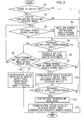
Fig. 2] Fig. 2 is a flow chart showing an operation of the vehicle control system according to the embodiment of the present invention. - [
Fig. 3] Fig. 3 is a timing chart showing an operation of the vehicle control system according to the embodiment of the present invention. - [
Fig. 4] Fig. 4 is a timing chart showing another operation of the vehicle control system according to the embodiment of the present invention. - Hereinafter, the embodiment of the present invention will be explained by reference to the drawings.
- A
vehicle control system 1 illustrated as the embodiment of the present invention is configured, for example, as shown inFig. 1 . Thevehicle control system 1 is implemented in an electric vehicle. The electric vehicle converts electrical energy stored in abattery 11 installed in the electric vehicle into electric power to drive. Note that, in the figure, the solid lines connecting components each represent a transfer of electricity, and the dotted lines connecting components each represent a transfer of control signals. - The
vehicle control system 1 can be connected to anexternal power source 50 via anexternal charging cable 40. - The
external power source 50 includes acommercial power source 52 and apower source socket 51. Thecommercial power source 52 is a supply source of a commercial power supply of, for example, 50 Hz and 200 V. Thepower source socket 51 is an interface connected to theexternal charging cable 40. - The
external charging cable 40 includes apower source plug 43, acontroller 42 and acharging plug 41. Thepower source plug 43 is connected to thepower source socket 51 of theexternal power source 50. Thecontroller 42 functions to detect a short circuit in the system during charge to break wires and functions to send current capacity signals to the vehicle. Thecharging plug 41 is connected to acharging port 24 of thevehicle control system 1. - The
vehicle control system 1 can be connected to acharger 60 via acharger charging cable 61. - The
charger 60 is a charging device located outside the vehicle for supplying charging electricity directly to the electric vehicle. Thecharger charging cable 61 includes acharging plug 61a and aconnection cable 61b. Thevehicle control system 1 thus can charge abattery device 10 with the electricity. - The
vehicle control system 1 can communicate with auser terminal 80 via a receivingcenter 70 by radio. Here, thereceiving center 70 and theuser terminal 80 may be connected together through a wire. - The
receiving center 70 is a data center that communicates information with acommunication device 26 in thevehicle control system 1. Thereceiving center 70 and thecommunication device 26 can transfer radio signals therebetween. Theuser terminal 80 communicates information with thecommunication device 26 via thereceiving center 70. Theuser terminal 80 is, for example, a mobile phone, a smart phone, or a PC. - The
vehicle control system 1 includes thebattery device 10, a vehicle ECU 21, apower supply device 22, acharging relay 23, twocharging ports communication device 26. - The
charging port 24 is a connector for connecting the electric vehicle with theexternal power source 50 via theexternal charging cable 40. Thecharging port 24 supplies AC power supplied from theexternal power source 50 to thepower supply device 22 via theexternal charging cable 40. - The
charging port 25 is a connector for connecting the electric vehicle with thecharger 60 via thecharger charging cable 61. Thecharging port 25 supplies DC power supplied from thecharger 60 to thecharging relay 23 via thecharger charging cable 61. Thecharging relay 23 opens or closes in accordance with the control by thepower supply device 22 so as to connect or break between thecharging port 25 and thebattery device 10. Thecharging relay 23 thus connects or breaks between thecharger 60 and thebattery device 10. - The
power supply device 22 converts the AC power supplied from theexternal power source 50 into DC power and raises the voltage of the DC power so as to supply the DC power to thebattery device 10. Thepower supply device 22 also controls the opening and closing operation of thecharging relay 23. - The vehicle ECU 21 is a control device that determines the conditions of the electric vehicle to perform overall control including driving control and charging control. The vehicle ECU 21 controls the
battery 11 of the electric vehicle to keep at appropriate temperature. The vehicle ECU 21 keeps controlling the temperature not only when the electric vehicle is driving but also when the power of the electric vehicle is turned off. During the control, thevehicle ECU 21 activates abattery heater 14 to prevent a decrease in temperature of thebattery 11. Accordingly, deterioration or freezing of thebattery 11 can be prevented. The vehicle ECU 21 uses the electricity of theexternal power source 50 to regulate the temperature of thebattery 11 when theexternal power source 50 is connected to the electric vehicle. The vehicle ECU 21 may regulate the temperature of thebattery 11 by use of the DC power supplied from thecharger 60. The vehicle ECU 21 uses the electricity of thebattery 11 to regulate the temperature of thebattery 11 when the electric vehicle is not connected with theexternal power source 50 and is thus in a plug-off state. - The vehicle ECU 21 also determines whether predetermined conditions for activating an auxiliary device such as the
battery heater 14 or an air conditioningauxiliary system 33 are fulfilled and whether theexternal power source 50 is available. When theexternal power source 50 is not available, the vehicle ECU 21 directs thecommunication device 26 to transmit (provide) information about predetermined notice to the user of the electric vehicle. Thevehicle ECU 21 thus serves as a control means and as a vehicle information providing device. The operation of the vehicle ECU 21 will be explained in detail below. - The
communication device 26 serves as a communication means capable of transmitting information about the electric vehicle to the outside of the electric vehicle. Thecommunication device 26 transmits predetermined information to the receivingcenter 70 in accordance with the control by thevehicle ECU 21. The information transmitted from thecommunication device 26 to the outside of the electric vehicle includes predetermined notice provided to the user of the electric vehicle. Here, addresses such as an IP address and an email address assigned to theuser terminal 80 are preliminarily entered in thecommunication device 26. The predetermined notice includes, for example, notice to urge the user to supply the electricity from theexternal power source 50 to the electric vehicle. - The
battery device 10 includes thebattery 11, abattery ECU 12, abattery relay 13, thebattery heater 14, abattery heater relay 15, and atemperature detection device 16. - The
battery 11 includes an assembled battery capable of charge and discharge of electricity. Thebattery 11 can be charged with electricity supplied from theexternal power source 50 located outside the electric vehicle. Thebattery device 10 serves as an electricity generation device for converting the electricity stored in thebattery 11 into DC power to supply it to each component in the electric vehicle. - The
battery relay 13 is connected to thebattery 11 on one side thereof. Thebattery relay 13 is connected, on the other side, to thebattery heater relay 15, aninverter 32, the chargingrelay 23 and the like. Thebattery relay 13 functions to connect or break between theexternal power source 50, thecharger 60 or theinverter 32 and thebattery 11. The operation of thebattery relay 13 is controlled by thebattery ECU 12. - The
battery heater 14 functions to regulate the temperature of thebattery 11. Thebattery heater 14 generates heat to keep thebattery 11 at predetermined temperature. Thebattery heater relay 15 functions to connect or break between theexternal power supply 50 or thecharger 60 and thebattery heater 14. The operation of thebattery heater relay 15 is controlled by thebattery ECU 12. The heat generation of thebattery heater 14 is turned on/off by the operation of thebattery heater relay 15. - The
temperature detection device 16 detects the temperature of thebattery 11. The battery temperature detected by thetemperature detection device 16 is read in thebattery ECU 12. - The
battery ECU 12 controls theentire battery device 10. Thebattery ECU 12 monitors the conditions of thebattery 11 including the battery temperature and the remaining battery level (SOC). Thebattery ECU 12 controls the opening and closing operation of thebattery relay 13 to regulate the charge and discharge of thebattery 11. Thebattery ECU 12 controls the opening and closing operation of thebattery heater relay 15 to control thebattery heater 14. - The
battery ECU 12 outputs, to thevehicle ECU 21, a request to regulate the temperature of the battery 11 (hereinafter, referred to as "a battery temperature regulation request") depending on the battery temperature detected by thetemperature detection device 16. Thebattery ECU 12 also transmits information about the remaining battery level to thevehicle ECU 21. - The
vehicle control system 1 includes adrive motor 31, theinverter 32, the air conditioningauxiliary system 33, a DC/DC converter 34, and a light electricalauxiliary system 35. - The
drive motor 31 generates drive torque of the electric vehicle. Thedrive motor 31 is activated by AC power supplied from theinverter 32. Theinverter 32 converts DC power supplied from thebattery 11 into AC power. Here, theinverter 32 controls a voltage and frequency of AC power to supply the AC power to thedrive motor 31. - The air conditioning
auxiliary system 33 operates in such a manner as to consume electricity supplied from theexternal power source 50 or thebattery 11 installed in the electric vehicle. The air conditioningauxiliary system 33 includes a cooling device and a heating device for regulating temperature in the interior of the electric vehicle and thebattery device 10. The air conditioningauxiliary system 33 is activated by DC power supplied from thebattery 11. The air conditioningauxiliary system 33 supplies cooled air or heated air of which temperature is regulated to thebattery device 10 via anair supply passage 33a. - The light electrical
auxiliary system 35 includes a 12V battery, head lamps, wipers, meters, a navigation system, lightings, and several types of control units. The light electricalauxiliary system 35 is activated by DC power supplied from the DC/DC converter 34. The DC/DC converter 34 lowers a voltage of DC power of thebattery 11 as appropriate (for example, 12 V) to supply the DC power to the light electricalauxiliary system 35. - Note that the auxiliary device installed in the electric vehicle includes a component other than the temperature regulation means for the
battery 11 such as thebattery heater 14 or the air conditioningauxiliary system 33. An example of the other auxiliary device is a device for automatically charging the 12V battery with electricity of thebattery 11. Such an automatic charging function is activated by the electric vehicle automatically by use of the electricity of thebattery 11 regardless of intention of the user. - Next, the operation of providing predetermined notice to the user of the electric vehicle in the vehicle control system when the predetermined conditions for activating the auxiliary device are fulfilled and when the
external power source 50 is not available, will be explained by reference to the flow chart shown inFig. 2 . - First, in step S1, the
vehicle ECU 21 determines whether the power of the electric vehicle is OFF. When thevehicle ECU 21 determines that a power switch or the like (not shown in the figure) has been turned off, the process proceeds to step S2. When the power of the electric vehicle is ON, thevehicle ECU 21 determines that the user stays in the vehicle because the user is driving or the like and finishes the process so as not to provide any notice to the user. - In the following step S2, the
vehicle ECU 21 determines whether the battery temperature regulation request is made. For example, thetemperature detection device 16 detects the battery temperature reaching a predetermined temperature (for example, - 17°C or lower). The
battery ECU 12 outputs the battery temperature regulation request to thevehicle ECU 21 when thebattery ECU 12 determines that the battery temperature detected by thetemperature detection device 16 is the predetermined temperature or lower. When the battery temperature regulation request is output to thevehicle ECU 21, the process proceeds to step S3. When there is no battery temperature regulation request, thevehicle ECU 21 finishes the process so as not to provide any notice to the user. - In the following step S3, the
vehicle ECU 21 determines whether the electricity from theexternal power source 50 is available. Namely, thevehicle ECU 21 determines whether the electricity from theexternal power source 50 can be used for the battery temperature regulation request. When the electricity from theexternal power source 50 is available, the process proceeds to step S4. - In step S4, the
vehicle ECU 21 uses the electricity from theexternal power source 50 to conduct the regulation of temperature of thebattery 11. According to the control by thevehicle ECU 21, thevehicle control system 1 activates thebattery heater 14 or the air conditioningauxiliary system 33 to regulate the temperature of thebattery 11. When the temperature of thebattery 11 is low, thevehicle control system 1 turns on thebattery heater relay 15 to activate thebattery heater 14 so as to increase the temperature of thebattery 11. Alternatively, when the temperature of thebattery 11 is low, thevehicle control system 1 may activate the heating device of the air conditioningauxiliary system 33 so as to supply heated air to thebattery 11 via theair supply passage 33a. When decreasing the temperature of thebattery 11, thevehicle control system 1 may supply cooled air to thebattery 11 from the air conditioningauxiliary system 33 via theair supply passage 33a. - In step S3, when the
vehicle ECU 21 determines that the electricity from theexternal power source 50 is not available, the process proceeds to step S5. In step S5, thevehicle ECU 21 determines whether the remaining battery level of thebattery 11 is a predetermined value or higher. For example, thevehicle ECU 21 determines whether SOC as the remaining battery level is 30% or higher. When the remaining battery level is not the predetermined value or higher, the process proceeds to step S6. When the remaining battery level is the predetermined value or higher, the process proceeds to step S8. - In step S6, the
vehicle ECU 21 determines whether a predetermined time or more has elapsed since the point where the power of the electric vehicle is turned off. When the predetermined time or more has elapsed since the point where the power of the electric vehicle is turned off, the process proceeds to step S7. When the predetermined time or more has not passed yet, the process returns to step S3. - In step S7, the
vehicle ECU 21 controls thecommunication device 26 installed in the electric vehicle so as to provide the user with predetermined notice. In particular, thevehicle ECU 21 directs thecommunication device 26 to transmit information notifying that the user is urged to bring theexternal power source 50 to a state capable of supplying electricity to the electric vehicle (temperature regulation inability notice) because thevehicle ECU 21 cannot conduct the regulation of temperature of thebattery 11 in response to the battery temperature regulation request. This temperature regulation inability notice is transmitted from thecommunication device 26 to theuser terminal 80 via the receivingcenter 70. Theuser terminal 80, for example, displays the temperature regulation inability notice so as to notify the user of the temperature regulation inability. - As described above, when the predetermined conditions that the battery temperature regulation request has been made, the remaining battery level is not the predetermined value or higher, and the predetermined time or more has elapsed since the point where the power of the electric vehicle is turned off, are fulfilled and when the electricity from the
external power source 50 is not available, thevehicle control system 1 provides the user with the temperature regulation inability notice. The predetermined conditions include at least the battery temperature regulation request. Namely, the predetermined conditions include the condition for activating thebattery heater 14 or the air conditioningauxiliary system 33. - When it is determined that the remaining battery level is not the predetermined value or higher (in step S5), the regulation of temperature of the
battery 11 is inhibited to prevent the remaining battery level from further decreasing due to the execution of the temperature regulation so as to avoid an excessive decrease in remaining driving range of the electric vehicle or a shortage of electricity of thebattery 11. - Further in step S6, the
vehicle control system 1 provides the user with the temperature regulation inability notice under the condition that the predetermined time or more has elapsed since the point where the power of the electric vehicle is turned off. Namely, there is a time lag before providing the temperature regulation inability notice. Thus, the notice is not provided until the predetermined time has elapsed in view of the step that the user brings the electricity of theexternal power source 50 to an available state by, for example, connecting theexternal charging cable 40 to the electric vehicle after the user turns off the power of the electric vehicle and gets out thereof. Although the predetermined time is an arbitrary time, the predetermined time may be set to several tens of minutes so as not to provide the user with the temperature regulation inability notice while the user is connecting theexternal charging cable 40 to the electric vehicle. - After the temperature regulation inability notice is provided, the
external power source 50 is conceived to be connected to thevehicle control system 1 via theexternal charging cable 40 by the user. Then, the determination in step S3 is YES so that the battery temperature regulation is conducted by use of the electricity from theexternal power source 50 in step S4. - In step S8 to which the process proceeds in step S5 when it is determined that the remaining battery level is the predetermined value or higher, the
vehicle control system 1 regulates the temperature of thebattery 11 by use of the electricity of thebattery 11. Thevehicle ECU 21 then controls thebattery ECU 12 so as to turn on thebattery relay 13 and thebattery heater relay 15. - In the following step S9, the
vehicle ECU 21 determines whether the predetermined time or more has elapsed since the point where the power of the electric vehicle is turned off. When the predetermined time or more has elapsed since the point where the power of the electric vehicle is turned off, the process proceeds to step S10. When the predetermined time or more has not passed yet, the process returns to step S5. - In step S10, the
vehicle ECU 21 controls thecommunication device 26 installed in the electric vehicle so as to provide the user with predetermined notice. In particular, thevehicle ECU 21 directs thecommunication device 26 to transmit information about a decrease of the remaining battery level (remaining battery level decrease notice) because the electricity of thebattery 11 is used to regulate the temperature of thebattery 11. The remaining battery level decrease notice may include notice that the user is urged to bring theexternal power source 50 to a state capable of supplying the electricity to the electric vehicle in order to avoid decreasing the remaining battery level. This remaining battery level decrease notice is transmitted from thecommunication device 26 to theuser terminal 80 via the receivingcenter 70. Theuser terminal 80, for example, displays the remaining battery level decrease notice so as to notify the user of the decrease of the remaining battery level. - As described above, when the predetermined conditions that the battery temperature regulation request has been made, the temperature of the
battery 11 has been regulated by use of the electricity of thebattery 11, and the predetermined time or more has elapsed since the point where the power of the electric vehicle is turned off, are fulfilled, thevehicle control system 1 provides the user with the remaining battery level decrease notice. The predetermined conditions include the battery temperature regulation request. Namely, the predetermined conditions include the condition for activating thebattery heater 14 or the air conditioningauxiliary system 33. - In the following step S11, the
vehicle ECU 21 determines whether the remaining battery level falls below the predetermined value. For example, thevehicle ECU 21 determines whether SOC as the remaining battery level falls below 30%. When the remaining battery level falls below the predetermined value, the process proceeds to step S12. When the remaining battery level is not below the predetermined value, thevehicle ECU 21 repeats the determination of step S11. - After transmitting the remaining battery level decrease notice in step S10, the
external power source 50 is conceived to be connected to thevehicle control system 1 via theexternal charging cable 40 by the user. In such a case, thevehicle ECU 21 may finish this process after detecting the connection of theexternal charging cable 40 and then conducting the regulation of temperature of thebattery 11 by use of the electricity from theexternal power source 50. - In step S12, the
vehicle ECU 21 stops regulating the temperature of thebattery 11 by use of the electricity of thebattery 11. Thevehicle ECU 21 then controls thebattery ECU 12 so as to turn off thebattery relay 13 and thebattery heater relay 15. Accordingly, an electricity shortage of thebattery 11 is prevented. - In the following step S13, the
vehicle ECU 21 directs thecommunication device 26 to transmit the information that the user is urged to bring theexternal power source 50 to a state capable of supplying the electricity to the electric vehicle (temperature regulation inability notice) because thevehicle ECU 21 cannot conduct the regulation of temperature of thebattery 11 in response to the battery temperature regulation request. This temperature regulation inability notice is transmitted from thecommunication device 26 to theuser terminal 80 via the receivingcenter 70. Theuser terminal 80, for example, displays the temperature regulation inability notice so as to notify the user of the temperature regulation inability. - As described above, the
vehicle ECU 21 determines whether the predetermined conditions including: (a) the power of the electric vehicle; (b) the battery temperature; (c) the availability of electricity of theexternal power source 50; and (d) the remaining battery level, for example, as shown inFig. 3 are fulfilled. In particular, thevehicle ECU 21 determines in step S1 that (a) the power of the electric vehicle is turned off. Thevehicle ECU 21 determines in step S2 that (b) the battery temperature is lower than or equal to the predetermined value Tth at which the battery temperature regulation request is made. Thevehicle ECU 21 determines in step S3 that (c) the electricity of theexternal power source 50 is not available. Thevehicle ECU 21 determines in step S5 that (d) the remaining battery level is lower than or equal to the predetermined value SOCth. - When the conditions (a), (b) and (d) are fulfilled and when the
external power source 50 is not available as indicated by condition (c), thevehicle ECU 21 does not conduct the regulation of temperature of thebattery 11 as indicated by condition (e). When thevehicle ECU 21 determines in step S6 that the predetermined time T has elapsed since the point where the power of the electric vehicle is turned off, thevehicle ECU 21 transmits the temperature regulation inability notice to theuser terminal 80 in step S7 as indicated by condition (f). - Alternatively, as shown in
Fig. 4 , thevehicle ECU 21 may conduct the regulation of temperature of thebattery 11 in a manner such that, after the power of the electric vehicle is turned off, thevehicle ECU 21 does not use the electricity of theexternal power source 50 as indicated by condition (c) but uses the electricity of thebattery 11 as indicated by condition (e). When the regulation of temperature of thebattery 11 is carried out as described above, the battery temperature increase as indicated by condition (b) but the remaining battery level gradually decreases as indicated by condition (d). - When the predetermined time T has elapsed since the point where the power of the electric vehicle is turned off, the
vehicle ECU 21 transmits, to theuser terminal 80, the remaining battery level decrease notice as indicated by condition (f). Subsequently, when the remaining battery level falls to or below the predetermined value SOCth as indicated by condition (d) and when the battery temperature is the predetermined value Tth or lower as indicated by condition (b), thevehicle ECU 21 stops regulating the temperature of thebattery 11 as indicated by condition (e). Further, thevehicle ECU 21 transmits, to theuser terminal 80, the temperature regulation inability notice as indicated by condition (f). - As explained in detail above, the vehicle control system illustrated as the embodiment conducts the control of transmitting the information about predetermined notice to the user of the electric vehicle when the predetermined conditions for activating the auxiliary device such as the
battery heater 14 are fulfilled and when theexternal power source 50 is not available. Thus, the vehicle control system can provide the user with the notice even when the electric vehicle is not connected with theexternal power source 50 and is thus in a plug-off state and thebattery heater 14 is activated in order to, for example, prevent a decrease in temperature of thebattery 11. - Accordingly, the vehicle control system can notify the user of a decrease of the remaining battery level that the user does not intend because of, for example, the regulation of temperature of the
battery 11, or deterioration or the like of thebattery 11 because of inability to regulate the temperature of thebattery 11. - In addition, the vehicle control system can provide the
user terminal 80 with the notice that the user is urged to bring theexternal power source 50 to a state capable of supplying the electricity to the electric vehicle even when the user leaves the electric vehicle. - In addition, the vehicle control system can prevent the remaining battery level from decreasing because of automatic operation which is conducted even when the power of the electric vehicle is OFF.
- The vehicle control system described above provides the notice under the predetermined condition that the request to activate the auxiliary device such as the
battery heater 14 is made but the auxiliary device cannot start or continue operating. Namely, the vehicle control system provides the user with the notice when it is determined in step S5 that the remaining battery level is the predetermined value or lower at the point where the battery temperature regulation request is made, or when it is determined in step S11 that the remaining battery level falls to or below the predetermined value as a result of consumption of electricity of thebattery 11. - The vehicle control system thus can provide the user with the notice that the user is urged to take an appropriate step when the auxiliary device such as the
battery heater 14 is required to operate but cannot start or continue operating because of a shortage of electricity of thebattery 11 or a fault in connection of theexternal charging cable 40. Accordingly, the risk of causing defects derived from a decrease of the remaining battery level of thebattery 11 of the electric vehicle can be reduced. - According to the vehicle control system, since the information notifying the user of the temperature regulation inability is transmitted when the auxiliary device cannot start or continue operating, the user can be urged to bring the
external power source 50 to a state capable of supplying the electricity to the electric vehicle because the temperature of thebattery 11 cannot be regulated. - The vehicle control system described above provides the notice under the predetermined condition that the auxiliary device starts operating by use of the electricity of the
battery 11. When the auxiliary device starts operating by use of the electricity of thebattery 11, the user can be urged to take a necessary step due to the notice. Accordingly the risk that the state of charge of thebattery 11 decreases while the user does not notice it, can be avoided. - The vehicle control system transmits the information notifying the user of the decrease of the remaining battery level when the auxiliary device starts operating by use of the electricity of the
battery 11. The vehicle control system thus can avoid the risk that the remaining battery level decreases because of the regulation of temperature of thebattery 11 by use of the electricity of thebattery 11. - The vehicle control system described above determines the predetermined conditions after a lapse of predetermined time from the point where the power of the electric vehicle is turned off, so as to avoid providing the notice to the user before the user brings the
external power source 50 to a state capable of supplying the electricity to the electric vehicle after the user parks the electric vehicle. For example, the vehicle control system can avoid providing the notice to the user before the user finishes connecting theexternal charging cable 40 or thecharger charging cable 60 to the electric vehicle. - The vehicle control system described above provides no notice to the user when the electric vehicle is in a state capable of driving, for example, in a driving mode. The vehicle control system thus can avoid providing the user with unnecessary notice when the auxiliary device is activated by use of the electricity of the
battery 11 during driving. - The vehicle control system described above is a device in which the auxiliary device regulates the temperature of the
battery 11 so as to transmit the notice to the user when the device is activated. The vehicle control system thus can provide the user with the notice that the user is required to bring theexternal power source 50 to a state capable of supplying the electricity to the electric vehicle even when the regulation of temperature of thebattery 11 is automatically carried out while the electric vehicle is stopped. - It should be noted that the embodiment described above is an example of the present invention. Thus, the present invention is not limited to the embodiment described above, and various modifications can, of course, be made depending on design or the like according to other embodiments without departing from the scope of claims.
- The entire content of Japanese Patent Application No.
P2012-205253 (filed on September 19, 2012 - The present invention can provide a user of a vehicle with predetermined notice when predetermined conditions for activating an auxiliary device are fulfilled and when an external power source is not available so as to prevent a remaining battery level of the vehicle from decreasing.
-
- 1
- BATTERY
- 14
- BATTERY HEATER
- 33
- AIR CONDITIONING AUXILIARY SYSTEM
- 35
- LIGHT ELECTRICAL AUXILIARY SYSTEM
- 26
- COMMUNICATION DEVICE
- 50
- EXTERNAL POWER SOURCE
- 12
- VEHICLE ECU
Claims (10)
- A vehicle control system comprising:a battery capable of being charged with electricity supplied from an external power source outside a vehicle;an auxiliary device configured to operate by consuming the electricity supplied from the external power source or the battery installed in the vehicle;a communication unit capable of transmitting information about the vehicle outward from the vehicle; anda control unit configured to direct the communication unit to transmit information about predetermined notice to a user of the vehicle when a predetermined condition for activating the auxiliary device is fulfilled and when the external power source is not available.
- The vehicle control system according to claim 1, wherein the predetermined condition is that a request for activating the auxiliary device is made but the auxiliary device cannot start or continue operating.
- The vehicle control system according to claim 2, wherein, when the predetermined condition is fulfilled, the control unit directs the communication unit to transmit information about temperature regulation inability to notify that the user is urged to bring the external power source to a state capable of supply the electricity to the vehicle because a temperature of the battery cannot be regulated.
- The vehicle control system according to claim 1, wherein the predetermined condition is that the auxiliary device starts operating by use of the electricity of the battery.
- The vehicle control system according to claim 4, wherein, when the predetermined condition is fulfilled, the control unit directs the communication unit to transmit information about a decrease in remaining battery level to notify that the remaining battery level decreases because a temperature of the battery is regulated by use of the electricity of the battery.
- The vehicle control system according to any one of claims 1 to 5, wherein the control unit determines the predetermined condition after a lapse of predetermined time from a point where a power of the vehicle is turned off.
- The vehicle control system according to any one of claims 1 to 5, wherein the control unit does not provide the notice when the vehicle is in a state capable of driving.
- The vehicle control system according to any one of claims 1 to 7, wherein the auxiliary device is a device for regulating the temperature of the battery.
- A vehicle information providing device for providing information about a vehicle including a battery capable of being charged with electricity supplied from an external power source outside the vehicle, an auxiliary device configured to operate by consuming the electricity supplied from the external power source or the battery installed in the vehicle, and a communication unit capable of transmitting the information about the vehicle outward from the vehicle, the vehicle information providing device comprising
a control unit configured to direct the communication unit to transmit information about predetermined notice to a user of the vehicle when a predetermined condition for activating the auxiliary device is fulfilled and when the external power source is not available. - A vehicle information providing method comprising:determining whether a predetermined condition for activating an auxiliary device is fulfilled and whether an external power source is available, the auxiliary device being configured to operate by consuming electricity supplied from the external power source outside a vehicle or a battery installed in the vehicle and charged with the electricity supplied from the external power source; anddirecting a communication unit to transmit information about predetermined notice to a user of the vehicle when the predetermined condition is fulfilled and when the external power source is not available, the communication unit being capable of transmitting information about the vehicle outward.
Applications Claiming Priority (2)
| Application Number | Priority Date | Filing Date | Title |
|---|---|---|---|
| JP2012205253 | 2012-09-19 | ||
| PCT/JP2013/072079 WO2014045776A1 (en) | 2012-09-19 | 2013-08-19 | Vehicle control system, vehicle information supply device, and vehicle information supply method |
Publications (3)
| Publication Number | Publication Date |
|---|---|
| EP2899058A1 true EP2899058A1 (en) | 2015-07-29 |
| EP2899058A4 EP2899058A4 (en) | 2015-09-02 |
| EP2899058B1 EP2899058B1 (en) | 2017-09-27 |
Family
ID=50341100
Family Applications (1)
| Application Number | Title | Priority Date | Filing Date |
|---|---|---|---|
| EP13839893.8A Active EP2899058B1 (en) | 2012-09-19 | 2013-08-19 | Vehicle control system, vehicle information supply device, and vehicle information supply method |
Country Status (6)
| Country | Link |
|---|---|
| US (1) | US9751423B2 (en) |
| EP (1) | EP2899058B1 (en) |
| JP (1) | JP6483441B2 (en) |
| CN (1) | CN104640734B (en) |
| RU (1) | RU2595168C1 (en) |
| WO (1) | WO2014045776A1 (en) |
Cited By (1)
| Publication number | Priority date | Publication date | Assignee | Title |
|---|---|---|---|---|
| DE102015205261A1 (en) * | 2015-03-24 | 2016-09-29 | Robert Bosch Gmbh | METHOD FOR OPERATING A HIGH TEMPERATURE BATTERY |
Families Citing this family (27)
| Publication number | Priority date | Publication date | Assignee | Title |
|---|---|---|---|---|
| US8367235B2 (en) | 2008-01-18 | 2013-02-05 | Mophie, Inc. | Battery pack, holster, and extendible processing and interface platform for mobile devices |
| JP6286191B2 (en) * | 2013-11-25 | 2018-02-28 | クラリオン株式会社 | In-vehicle communication device and control method thereof |
| JP6221836B2 (en) | 2014-02-28 | 2017-11-01 | トヨタ自動車株式会社 | Vehicle power management device |
| JP6036746B2 (en) * | 2014-04-25 | 2016-11-30 | トヨタ自動車株式会社 | vehicle |
| US10079496B2 (en) * | 2014-09-03 | 2018-09-18 | Mophie Inc. | Systems for managing charging devices based on battery health information |
| WO2016160113A2 (en) * | 2015-03-31 | 2016-10-06 | Crown Equipment Corporation | Method for controlling a functional system of a materials handling vehicle |
| USD861653S1 (en) | 2015-05-27 | 2019-10-01 | Mophie Inc. | Protective battery case for mobile communications device |
| JP6323615B2 (en) * | 2015-09-03 | 2018-05-16 | 日産自動車株式会社 | Vehicle management method and vehicle management apparatus |
| JP6520633B2 (en) * | 2015-10-15 | 2019-05-29 | トヨタ自動車株式会社 | Vehicle control system |
| JP6288133B2 (en) * | 2016-03-22 | 2018-03-07 | トヨタ自動車株式会社 | Automobile |
| JP6432552B2 (en) * | 2016-03-22 | 2018-12-05 | トヨタ自動車株式会社 | Automobile |
| JP6645377B2 (en) * | 2016-08-02 | 2020-02-14 | 株式会社デンソー | Air conditioning control device, air conditioning control method |
| JP6939416B2 (en) * | 2017-10-27 | 2021-09-22 | トヨタ自動車株式会社 | Delivery system and vehicle |
| US10516431B2 (en) | 2017-11-21 | 2019-12-24 | Mophie Inc. | Mobile device case for receiving wireless signals |
| US10696290B2 (en) | 2018-02-27 | 2020-06-30 | Ford Global Technologies, Llc | Hybrid vehicle and powertrain |
| JP7272772B2 (en) * | 2018-09-28 | 2023-05-12 | トヨタ自動車株式会社 | In-vehicle control device and charging system |
| EP3829948A4 (en) | 2018-12-14 | 2022-04-20 | Cummins, Inc. | End of battery state of charge (soc) vehicle system operation |
| USD940647S1 (en) | 2019-01-07 | 2022-01-11 | Mophie Inc. | Battery pack |
| JP7253952B2 (en) * | 2019-03-27 | 2023-04-07 | 株式会社Subaru | vehicle |
| JP7226124B2 (en) * | 2019-06-19 | 2023-02-21 | 株式会社デンソー | Battery condition monitor |
| KR102851396B1 (en) * | 2019-10-10 | 2025-08-26 | 주식회사 엘지에너지솔루션 | Apparatus for controlling heating pad |
| GB2598473B (en) * | 2019-10-21 | 2023-03-15 | Mcmurtry Automotive Ltd | Downforce system for a vehicle |
| GB2588394B (en) | 2019-10-21 | 2022-01-12 | Mcmurtry Automotive Ltd | Downforce system for a vehicle |
| JP7468109B2 (en) * | 2020-04-17 | 2024-04-16 | マツダ株式会社 | Vehicle Battery Control System |
| JP7528513B2 (en) * | 2020-04-20 | 2024-08-06 | マツダ株式会社 | Vehicle battery control system and vehicle battery control method |
| JP7311471B2 (en) * | 2020-08-28 | 2023-07-19 | 株式会社竹内製作所 | work vehicle |
| JP7561810B2 (en) * | 2022-11-11 | 2024-10-04 | 本田技研工業株式会社 | Battery temperature control method and control device |
Family Cites Families (43)
| Publication number | Priority date | Publication date | Assignee | Title |
|---|---|---|---|---|
| US4398081A (en) * | 1980-10-23 | 1983-08-09 | Mark H. Moad | Stand-by heating/power supply system for a motor vehicle |
| JP3125198B2 (en) | 1991-12-04 | 2001-01-15 | 本田技研工業株式会社 | Battery temperature control device for electric vehicle |
| JP3044975B2 (en) * | 1992-12-10 | 2000-05-22 | トヨタ自動車株式会社 | Battery heating device for electric vehicles |
| JP3400034B2 (en) | 1993-10-12 | 2003-04-28 | 本田技研工業株式会社 | Battery remaining capacity remote display for electric vehicles |
| JP3461394B2 (en) * | 1994-11-21 | 2003-10-27 | 本田技研工業株式会社 | Telephone control system for electric vehicles |
| JP2001063347A (en) * | 1999-08-26 | 2001-03-13 | Denso Corp | Vehicle air-conditioning control system |
| JP3711445B2 (en) * | 2001-02-21 | 2005-11-02 | 株式会社デンソー | Vehicle air conditioning charge control device and in-vehicle battery charge management device |
| US6627851B2 (en) * | 2001-12-07 | 2003-09-30 | Delphi Technologies, Inc. | Power control method for a motor vehicle electric window heater |
| JP2004142661A (en) * | 2002-10-25 | 2004-05-20 | Denso Corp | Power supply management device for vehicle |
| JP4504940B2 (en) * | 2006-04-14 | 2010-07-14 | 日立建機株式会社 | Work vehicle status display device |
| DE102006049148A1 (en) * | 2006-10-18 | 2008-04-30 | Beru Ag | Method for operating an electric heater in a motor vehicle |
| JP2008130007A (en) * | 2006-11-24 | 2008-06-05 | Denso Corp | In-vehicle emergency call device |
| JP2008211955A (en) * | 2007-02-28 | 2008-09-11 | Toyota Motor Corp | Charge control device for power storage mechanism for traveling |
| US7849944B2 (en) * | 2007-06-12 | 2010-12-14 | Ut-Battelle, Llc | Self-learning control system for plug-in hybrid vehicles |
| US8049460B2 (en) * | 2007-07-18 | 2011-11-01 | Tesla Motors, Inc. | Voltage dividing vehicle heater system and method |
| JP4228086B1 (en) * | 2007-08-09 | 2009-02-25 | トヨタ自動車株式会社 | vehicle |
| JP4591487B2 (en) * | 2007-08-24 | 2010-12-01 | トヨタ自動車株式会社 | HYBRID VEHICLE, HYBRID VEHICLE NOTIFICATION METHOD, AND COMPUTER-READABLE RECORDING MEDIUM CONTAINING PROGRAM FOR CAUSING COMPUTER TO EXECUTE THE NOTIFICATION METHOD |
| JP4341712B2 (en) * | 2007-09-10 | 2009-10-07 | トヨタ自動車株式会社 | Charge control device and charge control method for power storage mechanism |
| JP2009113674A (en) * | 2007-11-07 | 2009-05-28 | Toyota Motor Corp | Air conditioner for vehicles |
| JP4333798B2 (en) * | 2007-11-30 | 2009-09-16 | トヨタ自動車株式会社 | Charge control device and charge control method |
| JP4893653B2 (en) * | 2008-02-19 | 2012-03-07 | トヨタ自動車株式会社 | Vehicle, rechargeable battery state of charge estimation method and vehicle control method |
| JP4325728B1 (en) * | 2008-05-12 | 2009-09-02 | トヨタ自動車株式会社 | Hybrid vehicle and power control method for hybrid vehicle |
| US8154149B2 (en) * | 2009-05-01 | 2012-04-10 | General Electric Company | Method and apparatus for charging a vehicle energy storage system |
| WO2010134163A1 (en) * | 2009-05-19 | 2010-11-25 | トヨタ自動車株式会社 | Hybrid vehicle and control method of same |
| JP2011050162A (en) * | 2009-08-26 | 2011-03-10 | Toyota Motor Corp | Vehicle |
| EP2476574B1 (en) * | 2009-09-09 | 2014-10-22 | Toyota Jidosha Kabushiki Kaisha | Power supply system for vehicle and method of controlling same |
| WO2011043703A1 (en) * | 2009-10-09 | 2011-04-14 | Volvo Lastvagnar Ab | Apparatus and method for controlling the temperature of a battery in a hybrid electric vehicle |
| WO2011077980A1 (en) * | 2009-12-25 | 2011-06-30 | 株式会社ヴァレオジャパン | Safety device of battery temperature control system |
| JP5427021B2 (en) * | 2009-12-25 | 2014-02-26 | 株式会社ヴァレオジャパン | Battery temperature control device |
| JP5435721B2 (en) | 2010-01-19 | 2014-03-05 | 株式会社ヴァレオジャパン | Safety device for battery temperature control system |
| JP5263242B2 (en) * | 2010-08-24 | 2013-08-14 | 三菱自動車工業株式会社 | Air conditioning controller |
| WO2012081104A1 (en) | 2010-12-16 | 2012-06-21 | トヨタ自動車株式会社 | Vehicle control device and vehicle control method |
| US8914173B2 (en) * | 2010-12-21 | 2014-12-16 | GM Global Technology Operations LLC | Method and system for conditioning an energy storage system (ESS) for a vehicle |
| US9318909B2 (en) | 2010-12-21 | 2016-04-19 | Volvo Truck Corporation | Method for controlling a power supply system of an automotive vehicle and power supply system adapted to such a method |
| JP5375849B2 (en) | 2011-02-10 | 2013-12-25 | 株式会社デンソー | VEHICLE CHARGE CONTROL DEVICE AND VEHICLE CHARGE CONTROL SYSTEM |
| JP5736860B2 (en) * | 2011-03-11 | 2015-06-17 | 日産自動車株式会社 | Battery charge control device |
| JP6042055B2 (en) * | 2011-07-20 | 2016-12-14 | スズキ株式会社 | Air conditioner for vehicles |
| JP5772334B2 (en) * | 2011-07-20 | 2015-09-02 | スズキ株式会社 | Air conditioner for vehicles |
| JP5858260B2 (en) * | 2012-02-22 | 2016-02-10 | トヨタ自動車株式会社 | Vehicle remote control system, server, and remote control terminal |
| JP6013857B2 (en) * | 2012-09-28 | 2016-10-25 | 株式会社神戸製鋼所 | Secondary battery charge / discharge controller for construction machinery |
| JP6149575B2 (en) * | 2013-07-29 | 2017-06-21 | 三菱自動車工業株式会社 | Vehicle warm-up control device |
| JP6191042B2 (en) * | 2013-08-29 | 2017-09-06 | 三菱自動車工業株式会社 | Electric vehicle charging system |
| US9037334B1 (en) * | 2014-01-15 | 2015-05-19 | Robert L. Cole | Electric vehicle having a dual battery system |
-
2013
- 2013-08-19 WO PCT/JP2013/072079 patent/WO2014045776A1/en not_active Ceased
- 2013-08-19 US US14/429,244 patent/US9751423B2/en active Active
- 2013-08-19 RU RU2015114559/11A patent/RU2595168C1/en active
- 2013-08-19 EP EP13839893.8A patent/EP2899058B1/en active Active
- 2013-08-19 JP JP2014536692A patent/JP6483441B2/en active Active
- 2013-08-19 CN CN201380048380.XA patent/CN104640734B/en active Active
Cited By (1)
| Publication number | Priority date | Publication date | Assignee | Title |
|---|---|---|---|---|
| DE102015205261A1 (en) * | 2015-03-24 | 2016-09-29 | Robert Bosch Gmbh | METHOD FOR OPERATING A HIGH TEMPERATURE BATTERY |
Also Published As
| Publication number | Publication date |
|---|---|
| WO2014045776A1 (en) | 2014-03-27 |
| RU2595168C1 (en) | 2016-08-20 |
| CN104640734A (en) | 2015-05-20 |
| EP2899058B1 (en) | 2017-09-27 |
| US20150210181A1 (en) | 2015-07-30 |
| CN104640734B (en) | 2016-07-13 |
| US9751423B2 (en) | 2017-09-05 |
| JPWO2014045776A1 (en) | 2016-08-18 |
| EP2899058A4 (en) | 2015-09-02 |
| JP6483441B2 (en) | 2019-03-13 |
Similar Documents
| Publication | Publication Date | Title |
|---|---|---|
| EP2899058B1 (en) | Vehicle control system, vehicle information supply device, and vehicle information supply method | |
| US9073444B2 (en) | Battery charging system for vehicle and battery charge controller in the same | |
| US11046200B2 (en) | On-board control device | |
| CN105480103B (en) | The off-board charger of high-voltage battery | |
| KR101455550B1 (en) | Charge control apparatus for vehicle | |
| EP2299556B1 (en) | Battery charging and electrical energy delivery system and battery operated system | |
| CA2568875C (en) | System and method for electrical energy switching and control in a vehicle | |
| CN107323433B (en) | Fault detection and maintenance method and device for vehicle and storage medium | |
| KR20130138954A (en) | Bi-directional power supply device for smart grid electric vehicle and bi-directional power supply method using the same | |
| CN113263931A (en) | Pilot control circuit for charging a vehicle with a charging station | |
| CN111319509B (en) | Control method and system for working mode of battery replacement in battery replacement station | |
| KR102386115B1 (en) | Air conditioner without engine running for heating and cooling for truck | |
| US9789771B2 (en) | Single battery architecture for electrification vehicle | |
| WO2013054435A1 (en) | Electric vehicle charging device | |
| USRE46230E1 (en) | Inverter with network interface | |
| US10894480B2 (en) | Supplying of low-voltage on-board electrical systems of vehicles having an electric drive | |
| CN118139760A (en) | Method for charging a traction battery of an electrically drivable vehicle, vehicle and charging device | |
| CN113492702A (en) | Bidirectional vehicle-mounted charger, vehicle-mounted power supply system, charging control method and automobile | |
| KR20200134557A (en) | System and method for reserved charging battery of vehicle | |
| CN111976544B (en) | Battery thermal management system and thermal management method for vehicle | |
| KR20190100261A (en) | Methods and systems for the management of rechargeable electric or hybrid vehicles | |
| CN112895980B (en) | Low-temperature charging method and device for new energy vehicles | |
| KR20200112212A (en) | Battery charging method for eco-friendly vehicle | |
| JP2017017766A (en) | Vehicle battery system | |
| CN121716629A (en) | Power supply system, power control method and related device |
Legal Events
| Date | Code | Title | Description |
|---|---|---|---|
| PUAI | Public reference made under article 153(3) epc to a published international application that has entered the european phase |
Free format text: ORIGINAL CODE: 0009012 |
|
| 17P | Request for examination filed |
Effective date: 20150320 |
|
| AK | Designated contracting states |
Kind code of ref document: A1 Designated state(s): AL AT BE BG CH CY CZ DE DK EE ES FI FR GB GR HR HU IE IS IT LI LT LU LV MC MK MT NL NO PL PT RO RS SE SI SK SM TR |
|
| AX | Request for extension of the european patent |
Extension state: BA ME |
|
| RA4 | Supplementary search report drawn up and despatched (corrected) |
Effective date: 20150804 |
|
| RIC1 | Information provided on ipc code assigned before grant |
Ipc: B60K 1/00 20060101ALI20150729BHEP Ipc: H01M 10/60 20140101ALI20150729BHEP Ipc: H01M 10/42 20060101ALI20150729BHEP Ipc: H02J 7/00 20060101ALI20150729BHEP Ipc: B60L 11/18 20060101AFI20150729BHEP Ipc: H02J 13/00 20060101ALI20150729BHEP Ipc: B60K 1/04 20060101ALI20150729BHEP Ipc: B60K 11/06 20060101ALI20150729BHEP Ipc: H01M 10/44 20060101ALI20150729BHEP Ipc: B60L 3/00 20060101ALI20150729BHEP Ipc: H01M 10/615 20140101ALI20150729BHEP Ipc: H01M 10/625 20140101ALI20150729BHEP Ipc: B60L 1/00 20060101ALI20150729BHEP Ipc: H01M 10/48 20060101ALI20150729BHEP Ipc: H01M 10/6571 20140101ALI20150729BHEP Ipc: H01M 10/663 20140101ALI20150729BHEP |
|
| DAX | Request for extension of the european patent (deleted) | ||
| 17Q | First examination report despatched |
Effective date: 20160726 |
|
| STAA | Information on the status of an ep patent application or granted ep patent |
Free format text: STATUS: EXAMINATION IS IN PROGRESS |
|
| GRAP | Despatch of communication of intention to grant a patent |
Free format text: ORIGINAL CODE: EPIDOSNIGR1 |
|
| STAA | Information on the status of an ep patent application or granted ep patent |
Free format text: STATUS: GRANT OF PATENT IS INTENDED |
|
| INTG | Intention to grant announced |
Effective date: 20170511 |
|
| GRAS | Grant fee paid |
Free format text: ORIGINAL CODE: EPIDOSNIGR3 |
|
| GRAJ | Information related to disapproval of communication of intention to grant by the applicant or resumption of examination proceedings by the epo deleted |
Free format text: ORIGINAL CODE: EPIDOSDIGR1 |
|
| GRAL | Information related to payment of fee for publishing/printing deleted |
Free format text: ORIGINAL CODE: EPIDOSDIGR3 |
|
| STAA | Information on the status of an ep patent application or granted ep patent |
Free format text: STATUS: EXAMINATION IS IN PROGRESS |
|
| INTC | Intention to grant announced (deleted) | ||
| GRAR | Information related to intention to grant a patent recorded |
Free format text: ORIGINAL CODE: EPIDOSNIGR71 |
|
| STAA | Information on the status of an ep patent application or granted ep patent |
Free format text: STATUS: GRANT OF PATENT IS INTENDED |
|
| GRAA | (expected) grant |
Free format text: ORIGINAL CODE: 0009210 |
|
| STAA | Information on the status of an ep patent application or granted ep patent |
Free format text: STATUS: THE PATENT HAS BEEN GRANTED |
|
| INTG | Intention to grant announced |
Effective date: 20170817 |
|
| RAP1 | Party data changed (applicant data changed or rights of an application transferred) |
Owner name: NISSAN MOTOR CO., LTD. |
|
| AK | Designated contracting states |
Kind code of ref document: B1 Designated state(s): AL AT BE BG CH CY CZ DE DK EE ES FI FR GB GR HR HU IE IS IT LI LT LU LV MC MK MT NL NO PL PT RO RS SE SI SK SM TR |
|
| REG | Reference to a national code |
Ref country code: GB Ref legal event code: FG4D |
|
| REG | Reference to a national code |
Ref country code: CH Ref legal event code: EP |
|
| REG | Reference to a national code |
Ref country code: AT Ref legal event code: REF Ref document number: 931624 Country of ref document: AT Kind code of ref document: T Effective date: 20171015 |
|
| REG | Reference to a national code |
Ref country code: IE Ref legal event code: FG4D |
|
| REG | Reference to a national code |
Ref country code: DE Ref legal event code: R096 Ref document number: 602013027287 Country of ref document: DE |
|
| PG25 | Lapsed in a contracting state [announced via postgrant information from national office to epo] |
Ref country code: NO Free format text: LAPSE BECAUSE OF FAILURE TO SUBMIT A TRANSLATION OF THE DESCRIPTION OR TO PAY THE FEE WITHIN THE PRESCRIBED TIME-LIMIT Effective date: 20171227 Ref country code: FI Free format text: LAPSE BECAUSE OF FAILURE TO SUBMIT A TRANSLATION OF THE DESCRIPTION OR TO PAY THE FEE WITHIN THE PRESCRIBED TIME-LIMIT Effective date: 20170927 Ref country code: HR Free format text: LAPSE BECAUSE OF FAILURE TO SUBMIT A TRANSLATION OF THE DESCRIPTION OR TO PAY THE FEE WITHIN THE PRESCRIBED TIME-LIMIT Effective date: 20170927 Ref country code: LT Free format text: LAPSE BECAUSE OF FAILURE TO SUBMIT A TRANSLATION OF THE DESCRIPTION OR TO PAY THE FEE WITHIN THE PRESCRIBED TIME-LIMIT Effective date: 20170927 Ref country code: SE Free format text: LAPSE BECAUSE OF FAILURE TO SUBMIT A TRANSLATION OF THE DESCRIPTION OR TO PAY THE FEE WITHIN THE PRESCRIBED TIME-LIMIT Effective date: 20170927 |
|
| REG | Reference to a national code |
Ref country code: NL Ref legal event code: MP Effective date: 20170927 |
|
| REG | Reference to a national code |
Ref country code: LT Ref legal event code: MG4D |
|
| REG | Reference to a national code |
Ref country code: AT Ref legal event code: MK05 Ref document number: 931624 Country of ref document: AT Kind code of ref document: T Effective date: 20170927 |
|
| PG25 | Lapsed in a contracting state [announced via postgrant information from national office to epo] |
Ref country code: GR Free format text: LAPSE BECAUSE OF FAILURE TO SUBMIT A TRANSLATION OF THE DESCRIPTION OR TO PAY THE FEE WITHIN THE PRESCRIBED TIME-LIMIT Effective date: 20171228 Ref country code: LV Free format text: LAPSE BECAUSE OF FAILURE TO SUBMIT A TRANSLATION OF THE DESCRIPTION OR TO PAY THE FEE WITHIN THE PRESCRIBED TIME-LIMIT Effective date: 20170927 Ref country code: BG Free format text: LAPSE BECAUSE OF FAILURE TO SUBMIT A TRANSLATION OF THE DESCRIPTION OR TO PAY THE FEE WITHIN THE PRESCRIBED TIME-LIMIT Effective date: 20171227 Ref country code: RS Free format text: LAPSE BECAUSE OF FAILURE TO SUBMIT A TRANSLATION OF THE DESCRIPTION OR TO PAY THE FEE WITHIN THE PRESCRIBED TIME-LIMIT Effective date: 20170927 |
|
| PG25 | Lapsed in a contracting state [announced via postgrant information from national office to epo] |
Ref country code: NL Free format text: LAPSE BECAUSE OF FAILURE TO SUBMIT A TRANSLATION OF THE DESCRIPTION OR TO PAY THE FEE WITHIN THE PRESCRIBED TIME-LIMIT Effective date: 20170927 |
|
| PG25 | Lapsed in a contracting state [announced via postgrant information from national office to epo] |
Ref country code: CZ Free format text: LAPSE BECAUSE OF FAILURE TO SUBMIT A TRANSLATION OF THE DESCRIPTION OR TO PAY THE FEE WITHIN THE PRESCRIBED TIME-LIMIT Effective date: 20170927 Ref country code: RO Free format text: LAPSE BECAUSE OF FAILURE TO SUBMIT A TRANSLATION OF THE DESCRIPTION OR TO PAY THE FEE WITHIN THE PRESCRIBED TIME-LIMIT Effective date: 20170927 Ref country code: ES Free format text: LAPSE BECAUSE OF FAILURE TO SUBMIT A TRANSLATION OF THE DESCRIPTION OR TO PAY THE FEE WITHIN THE PRESCRIBED TIME-LIMIT Effective date: 20170927 |
|
| PG25 | Lapsed in a contracting state [announced via postgrant information from national office to epo] |
Ref country code: SM Free format text: LAPSE BECAUSE OF FAILURE TO SUBMIT A TRANSLATION OF THE DESCRIPTION OR TO PAY THE FEE WITHIN THE PRESCRIBED TIME-LIMIT Effective date: 20170927 Ref country code: IT Free format text: LAPSE BECAUSE OF FAILURE TO SUBMIT A TRANSLATION OF THE DESCRIPTION OR TO PAY THE FEE WITHIN THE PRESCRIBED TIME-LIMIT Effective date: 20170927 Ref country code: AT Free format text: LAPSE BECAUSE OF FAILURE TO SUBMIT A TRANSLATION OF THE DESCRIPTION OR TO PAY THE FEE WITHIN THE PRESCRIBED TIME-LIMIT Effective date: 20170927 Ref country code: SK Free format text: LAPSE BECAUSE OF FAILURE TO SUBMIT A TRANSLATION OF THE DESCRIPTION OR TO PAY THE FEE WITHIN THE PRESCRIBED TIME-LIMIT Effective date: 20170927 Ref country code: EE Free format text: LAPSE BECAUSE OF FAILURE TO SUBMIT A TRANSLATION OF THE DESCRIPTION OR TO PAY THE FEE WITHIN THE PRESCRIBED TIME-LIMIT Effective date: 20170927 Ref country code: IS Free format text: LAPSE BECAUSE OF FAILURE TO SUBMIT A TRANSLATION OF THE DESCRIPTION OR TO PAY THE FEE WITHIN THE PRESCRIBED TIME-LIMIT Effective date: 20180127 |
|
| REG | Reference to a national code |
Ref country code: DE Ref legal event code: R097 Ref document number: 602013027287 Country of ref document: DE |
|
| REG | Reference to a national code |
Ref country code: FR Ref legal event code: PLFP Year of fee payment: 6 |
|
| PG25 | Lapsed in a contracting state [announced via postgrant information from national office to epo] |
Ref country code: DK Free format text: LAPSE BECAUSE OF FAILURE TO SUBMIT A TRANSLATION OF THE DESCRIPTION OR TO PAY THE FEE WITHIN THE PRESCRIBED TIME-LIMIT Effective date: 20170927 |
|
| PLBE | No opposition filed within time limit |
Free format text: ORIGINAL CODE: 0009261 |
|
| STAA | Information on the status of an ep patent application or granted ep patent |
Free format text: STATUS: NO OPPOSITION FILED WITHIN TIME LIMIT |
|
| PG25 | Lapsed in a contracting state [announced via postgrant information from national office to epo] |
Ref country code: PL Free format text: LAPSE BECAUSE OF FAILURE TO SUBMIT A TRANSLATION OF THE DESCRIPTION OR TO PAY THE FEE WITHIN THE PRESCRIBED TIME-LIMIT Effective date: 20170927 |
|
| 26N | No opposition filed |
Effective date: 20180628 |
|
| PG25 | Lapsed in a contracting state [announced via postgrant information from national office to epo] |
Ref country code: SI Free format text: LAPSE BECAUSE OF FAILURE TO SUBMIT A TRANSLATION OF THE DESCRIPTION OR TO PAY THE FEE WITHIN THE PRESCRIBED TIME-LIMIT Effective date: 20170927 |
|
| REG | Reference to a national code |
Ref country code: DE Ref legal event code: R079 Ref document number: 602013027287 Country of ref document: DE Free format text: PREVIOUS MAIN CLASS: B60L0011180000 Ipc: B60L0050500000 |
|
| PG25 | Lapsed in a contracting state [announced via postgrant information from national office to epo] |
Ref country code: MC Free format text: LAPSE BECAUSE OF FAILURE TO SUBMIT A TRANSLATION OF THE DESCRIPTION OR TO PAY THE FEE WITHIN THE PRESCRIBED TIME-LIMIT Effective date: 20170927 |
|
| REG | Reference to a national code |
Ref country code: CH Ref legal event code: PL |
|
| PG25 | Lapsed in a contracting state [announced via postgrant information from national office to epo] |
Ref country code: LI Free format text: LAPSE BECAUSE OF NON-PAYMENT OF DUE FEES Effective date: 20180831 Ref country code: CH Free format text: LAPSE BECAUSE OF NON-PAYMENT OF DUE FEES Effective date: 20180831 Ref country code: LU Free format text: LAPSE BECAUSE OF NON-PAYMENT OF DUE FEES Effective date: 20180819 |
|
| REG | Reference to a national code |
Ref country code: BE Ref legal event code: MM Effective date: 20180831 |
|
| REG | Reference to a national code |
Ref country code: IE Ref legal event code: MM4A |
|
| PG25 | Lapsed in a contracting state [announced via postgrant information from national office to epo] |
Ref country code: IE Free format text: LAPSE BECAUSE OF NON-PAYMENT OF DUE FEES Effective date: 20180819 |
|
| PG25 | Lapsed in a contracting state [announced via postgrant information from national office to epo] |
Ref country code: BE Free format text: LAPSE BECAUSE OF NON-PAYMENT OF DUE FEES Effective date: 20180831 |
|
| PG25 | Lapsed in a contracting state [announced via postgrant information from national office to epo] |
Ref country code: MT Free format text: LAPSE BECAUSE OF NON-PAYMENT OF DUE FEES Effective date: 20180819 |
|
| PG25 | Lapsed in a contracting state [announced via postgrant information from national office to epo] |
Ref country code: TR Free format text: LAPSE BECAUSE OF FAILURE TO SUBMIT A TRANSLATION OF THE DESCRIPTION OR TO PAY THE FEE WITHIN THE PRESCRIBED TIME-LIMIT Effective date: 20170927 |
|
| PG25 | Lapsed in a contracting state [announced via postgrant information from national office to epo] |
Ref country code: PT Free format text: LAPSE BECAUSE OF FAILURE TO SUBMIT A TRANSLATION OF THE DESCRIPTION OR TO PAY THE FEE WITHIN THE PRESCRIBED TIME-LIMIT Effective date: 20170927 |
|
| PG25 | Lapsed in a contracting state [announced via postgrant information from national office to epo] |
Ref country code: HU Free format text: LAPSE BECAUSE OF FAILURE TO SUBMIT A TRANSLATION OF THE DESCRIPTION OR TO PAY THE FEE WITHIN THE PRESCRIBED TIME-LIMIT; INVALID AB INITIO Effective date: 20130819 Ref country code: CY Free format text: LAPSE BECAUSE OF FAILURE TO SUBMIT A TRANSLATION OF THE DESCRIPTION OR TO PAY THE FEE WITHIN THE PRESCRIBED TIME-LIMIT Effective date: 20170927 Ref country code: MK Free format text: LAPSE BECAUSE OF NON-PAYMENT OF DUE FEES Effective date: 20170927 |
|
| PG25 | Lapsed in a contracting state [announced via postgrant information from national office to epo] |
Ref country code: AL Free format text: LAPSE BECAUSE OF FAILURE TO SUBMIT A TRANSLATION OF THE DESCRIPTION OR TO PAY THE FEE WITHIN THE PRESCRIBED TIME-LIMIT Effective date: 20170927 |
|
| PGFP | Annual fee paid to national office [announced via postgrant information from national office to epo] |
Ref country code: DE Payment date: 20250724 Year of fee payment: 13 |
|
| PGFP | Annual fee paid to national office [announced via postgrant information from national office to epo] |
Ref country code: GB Payment date: 20250725 Year of fee payment: 13 |
|
| PGFP | Annual fee paid to national office [announced via postgrant information from national office to epo] |
Ref country code: FR Payment date: 20250723 Year of fee payment: 13 |