EP2898610B1 - Signalisation dans un système de communication tdd - Google Patents
Signalisation dans un système de communication tdd Download PDFInfo
- Publication number
- EP2898610B1 EP2898610B1 EP12761614.2A EP12761614A EP2898610B1 EP 2898610 B1 EP2898610 B1 EP 2898610B1 EP 12761614 A EP12761614 A EP 12761614A EP 2898610 B1 EP2898610 B1 EP 2898610B1
- Authority
- EP
- European Patent Office
- Prior art keywords
- transmission
- extended
- node
- reception
- frame structure
- Prior art date
- Legal status (The legal status is an assumption and is not a legal conclusion. Google has not performed a legal analysis and makes no representation as to the accuracy of the status listed.)
- Active
Links
- 230000011664 signaling Effects 0.000 title claims description 94
- 238000004891 communication Methods 0.000 title claims description 38
- 230000005540 biological transmission Effects 0.000 claims description 60
- 238000000034 method Methods 0.000 claims description 21
- 238000004590 computer program Methods 0.000 claims description 10
- 238000013468 resource allocation Methods 0.000 claims description 4
- 235000008694 Humulus lupulus Nutrition 0.000 claims description 3
- 230000015654 memory Effects 0.000 description 14
- 230000006870 function Effects 0.000 description 6
- 238000005516 engineering process Methods 0.000 description 4
- 238000005259 measurement Methods 0.000 description 4
- 238000012545 processing Methods 0.000 description 4
- 230000001413 cellular effect Effects 0.000 description 3
- 238000013459 approach Methods 0.000 description 2
- 230000008901 benefit Effects 0.000 description 2
- 230000001419 dependent effect Effects 0.000 description 2
- 238000013461 design Methods 0.000 description 2
- 230000008569 process Effects 0.000 description 2
- 238000001228 spectrum Methods 0.000 description 2
- WYWHKKSPHMUBEB-UHFFFAOYSA-N 6-Mercaptoguanine Natural products N1C(N)=NC(=S)C2=C1N=CN2 WYWHKKSPHMUBEB-UHFFFAOYSA-N 0.000 description 1
- 108010076504 Protein Sorting Signals Proteins 0.000 description 1
- 238000003491 array Methods 0.000 description 1
- 230000010267 cellular communication Effects 0.000 description 1
- 230000008859 change Effects 0.000 description 1
- 238000013500 data storage Methods 0.000 description 1
- 239000000835 fiber Substances 0.000 description 1
- 230000014509 gene expression Effects 0.000 description 1
- 230000000977 initiatory effect Effects 0.000 description 1
- 230000003993 interaction Effects 0.000 description 1
- 238000007726 management method Methods 0.000 description 1
- 238000010295 mobile communication Methods 0.000 description 1
- 230000003287 optical effect Effects 0.000 description 1
- 239000004065 semiconductor Substances 0.000 description 1
- 230000008054 signal transmission Effects 0.000 description 1
- 230000001360 synchronised effect Effects 0.000 description 1
- 229940095374 tabloid Drugs 0.000 description 1
Images


Classifications
-
- H—ELECTRICITY
- H04—ELECTRIC COMMUNICATION TECHNIQUE
- H04L—TRANSMISSION OF DIGITAL INFORMATION, e.g. TELEGRAPHIC COMMUNICATION
- H04L5/00—Arrangements affording multiple use of the transmission path
- H04L5/14—Two-way operation using the same type of signal, i.e. duplex
-
- H—ELECTRICITY
- H04—ELECTRIC COMMUNICATION TECHNIQUE
- H04B—TRANSMISSION
- H04B7/00—Radio transmission systems, i.e. using radiation field
- H04B7/24—Radio transmission systems, i.e. using radiation field for communication between two or more posts
- H04B7/26—Radio transmission systems, i.e. using radiation field for communication between two or more posts at least one of which is mobile
- H04B7/2643—Radio transmission systems, i.e. using radiation field for communication between two or more posts at least one of which is mobile using time-division multiple access [TDMA]
- H04B7/2656—Radio transmission systems, i.e. using radiation field for communication between two or more posts at least one of which is mobile using time-division multiple access [TDMA] for structure of frame, burst
-
- H—ELECTRICITY
- H04—ELECTRIC COMMUNICATION TECHNIQUE
- H04L—TRANSMISSION OF DIGITAL INFORMATION, e.g. TELEGRAPHIC COMMUNICATION
- H04L5/00—Arrangements affording multiple use of the transmission path
- H04L5/003—Arrangements for allocating sub-channels of the transmission path
- H04L5/0048—Allocation of pilot signals, i.e. of signals known to the receiver
Definitions
- the invention relates generally to mobile communication networks. More particularly, the invention relates to cross-node signaling performed in a time division duplex (TDD) communication scheme.
- TDD time division duplex
- Time division duplex is one possible communication scenario between two nodes, such as a base station (BS, eNB) and a user terminal (UT, UE).
- BS base station
- eNB user terminal
- UT user terminal
- UE user terminal
- an apparatus comprising processing means configured to cause the apparatus to perform any of the embodiments as described in the appended claims.
- an apparatus comprising a processing system configured to cause the apparatus to perform any of the embodiments as described in the appended claims.
- an apparatus comprising means for performing any of the embodiments as described in the appended claims.
- a first node operating under a time division duplex communication scheme applies a frame structure comprising an extended transmission part, wherein the extended transmission part at least partially overlaps in time domain with a reception part of a frame structure applied by at least one second node operating at least partially under the same transmission/reception pattern as the first node, and cause specific signaling to the at least one second node in the extended transmission part.
- a second node operating under a time division duplex communication scheme applies a frame structure comprising an extended reception part, wherein the extended reception part at least partially overlaps in time domain with a transmission part of a frame structure applied by at least one first node operating at least partially under the same transmission/reception pattern as the second node, and causes reception of a specific signaling from the at least one first node in the extended reception part.
- the overlapping transmission part of the frame structure applied by the at least one first node is a default transmission part or an extended transmission part.
- the second node may apply the frame structure comprising the extended reception part according to a predefined frequency for certain frames, and apply a default TDD frame structure for other frames.
- the second node may provide information of the frame structure applied by the second node to the first node, wherein the information indicates at least one of the following: a length of the frame, transmission-reception switching points in time domain, the number of RX parts, the number of TX parts, length of a guard period, whether or not the frame structure comprises the extended RX part, length of the default/extended RX part, number of the one or more extended RX parts.
- the second node may provide information indicating the frame structure to be applied to the first node.
- the extended reception part is located in the frame structure adjacent to a guard period, thus facilitating switching between transmission and reception.
- a duplex communication system is a point-to-point system composed of two connected nodes or devices that can communicate with one another in both directions.
- One specific type of duplex communication is a half-duplex system which provides communication in both directions, but only one direction at a time (not simultaneously, as in full duplex).
- the time allocations for communication in such a half-duplex system may be strictly predefined and controlled.
- a time division duplex (TDD) is a type of half duplex communication scheme in which the uplink (UL) is separated from the downlink (DL) by the allocation of different time slots in the same frequency band. In other words, UE and eNB are not allowed to transmit and receive at the same time.
- the local area systems may utilize a local-access-only frequency band including classical operator deployment and shared spectrum use, the license-exempt spectrum or white spaces to take advantage of the additional available bandwidth.
- the local area system may offer an efficient device-to-device (D2D) operation mode to establish ad-hoc networks. D2D operation is not discussed here in detail as the possibility to apply such D2D communication between two nodes in a wireless communication network is well-known to a person skilled in the art.
- D2D device-to-device
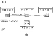
- FIG. 1 shows an example scenario of such a framed TDD based wireless backhaul relay network with a multi-hop communication topology.
- the functionality depicted in Fig. 1 can be called also as self-backhauling.
- AP access point
- the "slave" APs 102 and 104 may be fixed relays (inband) or even mobile devices functioning as APs.
- UEs (mobile devices) 106 may then be connected to at least one of the APs 100 to 104 in the system.
- the UE 106 is connected to the AP 102 as shown with a dashed line between them.
- the network nodes communicating with each other via the wireless links must have "opposite" frame structures, i.e. the neighboring connected devices/nodes are sending (TX) and receiving (RX) in turns.
- TX sending
- RX receiving
- the neighboring AP 102 is receiving, and vice versa.
- the neighboring nodes AP 100, AP 104 and UE 106
- the presence of such strict TX/RX switching times may be very important so that each of the nodes 100 to 106 are reliably able to listen and to receive data from the neighboring node(s) in turns.
- each AP 100 to 104 in the system may broadcast somewhere during its TX time a certain reference signal that may be heard and measured by the UEs 106 in the system.
- Such RS information is then used to make decisions when to switch the serving AP 100, 102 or 104 from the current one to one with better channel conditions, for example.
- the UE 106 is able to hear only the RSs which are sent during the UE 106 is in the "RX" mode, i.e. when it is listening the channel. Consequently, for example, the UE 106 in Figure 1 is not able to hear the RSs sent by the AP 100 or the AP 104 because they are sent during a time when the UE 106 is not in the "RX" mode.
- the reception of such RS signal measurements may be important because they are used not only for the initial access but also for handover scenarios. For example, LTE handover is based on the UE 106 measuring neighboring cells and reporting the measurement results to its home cell.
- the same problem is valid also for UL direction.
- there may be similar reference signal transmissions in the UL direction e.g. the UE 106 sends the RS so that the APs 100 to 104 may listen and measure the UL RS.
- This type of RS is called as sounding reference signal in LTE terminology.
- the problem described above is also valid in device-to-device (D2D) scenarios, where network nodes having the same TX/RX pattern are not able to hear one another. This problem may be a restricting factor, for example, in a D2D resource allocation signaling based on radio resource reservation requests and acknowledgements.
- the existing TDD frame structure includes a support for inter-node (a.k.a. cross-node) reference and control signaling among the network nodes following the same Tx/Rx pattern so that the signals may be listened by all UEs 106 in the network from all the APs 100 to 104 in the network substantially at the same time.
- the cross-node signals may then be used for example in determining the path loss and/or the need for communication among the neighboring nodes having the same TX/RX pattern in use (e.g. between UE 106 and AP 104 in Figure 1 ).
- a first node let us say the AP 100 as a non-limiting example, operating under the TDD communication scheme, applies, in step 300, a frame structure comprising an extended transmission (TX) part 200 (marked with vertical lines).
- the extended TX part 200 may be adjacent to the default TX part (marked with TX in Figures).
- the thick black lines in the Figures represent a TX/RX or RX/TX switch via a guard period (which is not explicitly shown in Figure 2A ).
- the extended TX part 200 may at least partially overlap in time domain with a reception (RX) part of a frame structure applied by at least one second node operating at least partially under the same TX/RX pattern as the first node 100.
- the overlapping RX part may be the default RX part or an extended RX part 202 (as illustrated later).
- the at least one second node may be, for example, the UE 106, as assumed in Figures 2A to 2D .
- the first node (AP 100) may advantageously transmit information (as shown with a dotted arrow in Figure 2A ) also to the UE 106 during the time period 204 because the UE 106 has a RX part valid at those time periods.
- the frame structures of the UE 106 and the AP 100 need not follow the same TX/RX pattern throughout the whole frame.
- the frame structure applied by the UE 106 may follow the same TX/RX pattern as the AP 100 with respect to the parts of the frames where the specific signaling is to be transmitted to the UE 106.
- the first node e.g. the AP 100
- the at least one second node e.g. the UE 106
- the UE 106 is connected to the AP 102 (as shown with the dashed line). In other words, the UE 106 may not have a direct TDD communication connection established with the AP 100. Also, as the multi-hop scenario may require that neighboring nodes have opposite TX/RX patterns, this may mean that the AP 100 and the UE 106 may apply originally the same default TX/RX pattern in their TDD communication because they are two hops away from each other.
- an alternative or an additional solution may be to extend the default RX part of the second node 106, as illustrated in Figures 2B and 4 .
- the second node 106 operating under the TDD communication scheme may, in step 400, apply a frame structure comprising an extended RX part 202 (marked with horizontal lines).
- the extended RX part 202 may be adjacent to a default RX part (marked with RX in Figures).
- the extended RX part 202 at least partially overlaps in time domain with the TX part of a frame structure applied by at least one first node (such as the AP 100 and/or AP 104) operating at least partially under the same TX/RX pattern as the UE 106.
- the overlapping TX part may be the default TX part or the extended TX part 200.
- the second node 106 may receive a specific signaling from the first node in the extended RX part 202, as shown with a dotted arrow in Figure 2B during the time period 206.
- both the extended TX part 200 and the extended RX part 202 may be used for the communication of data from the first node 100 to the second node 106.
- This embodiment allows for a longer time period 208 for the communication of the specific signaling to the second node 106, as shown with dotted arrows in Figure 2C .
- This embodiment may be advantageous for example in transmitting several types of data (such as the RS, control signaling, synchronization signaling, etc.) to the second node 106 as the time window may be longer than in the embodiments of Figures 2A and 2B .
- a possible location for the specific signaling is in relation of either one or both of TX-RX and RX-TX switching points of a frame in order to minimize the guard period (GP) overhead.
- at least one of an extended TX part 200 and an extended RX part 202 is located/placed in the frame next to the GP in order to facilitate switching between TX and RX phases.
- the switch point from TX to RX may also be referred to as the switching point from DL to UL, and vice versa.
- the proposed solution may comprise a predetermined DL and/or UL specific signal positions in the TDD frame. In this manner, the embodiments take into account the properties of the framed access of the TDD communication scheme and the applied frame structure.
- Figures 2A to 2C do not, for simplicity reasons, depict the guard periods (GPs) between the TX/RX parts.
- Figure 2D shows such GPs with blocks having diagonal lines. For example, it needs to be taken care that attached eNBs/APs do not send to each other on the backhaul links during the GP period of either one of the eNBs/APs. This may be guaranteed by including the GP as a part of cross-node specific signaling structure.
- the extended RX part 202 of the frame structure applied by the UE 106 may in an embodiment at least partially overlap in time domain with the extended TX part 200 of the frame structure applied by the AP 100, and vice versa.
- the specific signaling represented with a dotted arrow in Figure 2D may be performed during the overlap of the extended RX part 202 and the extended TX part 200 (e.g. during the time window 210).
- the specific signaling could be performed alternatively without applying any extended RX part 202.
- the specific signaling could be performed without applying any extended TX part 200.
- a common signaling position is advantageously arranged to the frame structures by extending the TX part of the node sending the signaling (such as the AP 100 in this example) and/or extending the RX part of a node receiving the signaling (such as the UE 106 in this example).
- the extended TX/RX position may be introduced at the end/beginning of either the default TX or the default RX period, depending on the phase of Tx/Rx cycle the given node operates.
- the TX part and the RX part may advantageously cause the TX part and the RX part (either the default TX/RX part or the extended TX/RX part 200/202) to overlap and thus form a field or time window which may be used for the specific signaling between these network nodes following the same TX/RX patterns.
- the specific signaling location is in relation of DL-UL or UL-DL (or both) switching point(s) of the TDD frame.
- the extended TX and/or RX part(s) locate in the protected part of the flexible TDD frame in order for it not to restrict the TX/RX flexibility of the frame.
- the embodiments do not exclude the possibility to maintain the UL-DL ratio flexibility of the underlying TDD frame structure.
- the frequency of the specific signaling (such as how many signaling positions there is in a frame and the frequency of frames containing such signaling position) may be predefined/configured on a network level.
- the nodes 100 and 106 may apply the frame structure comprising the extended TX/RX part 200/202 according to a predefined frequency for certain frames and apply the default TDD frame structure for the other frames.
- the embodiments may be dynamically reconfigured by the network according to prevailing needs. This is shown in Figure 5 where four consecutive frames are shown from the point of view of the AP 100, however, similar representation could be performed from the point of view of the UE 106 with extended RX parts being present (in case of DL signaling).
- first frame 502 there is one extended TX part 500A applied for transmission of data to the second node(s).
- second frame 504 there are two extended TX parts 500B and 500C applied.
- third frame 506 there are no extended TX parts but the default TX and RX parts are applied for the default TDD frame 506.
- fourth frame 508 there is one extended TX part 500D applied.
- the position of the extended TX/RX part may be altered from frame to frame. This information may be acquired from the network or acquired otherwise.
- the frequency of applying the frame structure comprising the one or more extended TX/RX parts may be configured by the network so that the extended TX/RX part will be applied regularly.
- the network may dynamically command the nodes to apply the frame structure with the extended TX/RX part when needed.
- the specific signaling position is common for the whole network (including all the cells of the specific network).
- An example related to this embodiment is presented in Figure 6A and 6B .
- the specific signaling comprises the broadcast of the RS in the downlink as a non-limiting example.
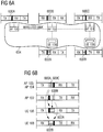
- the first node 100, 102, or 104 may cause specific signaling in the extended TX part 600A, 600B, 600C, respectively, to a plurality of second nodes 106 to 108 each associated with a certain network 604.
- This may be possible as the extended TX parts 600A, 600B, 600C at least partially overlap in time domain with the RX part of the frame structures applied by the plurality of second nodes 106 to 108, as shown in Figure 6B .
- the overlapping RX part may be either the default RX part or the extended RX part 602A, 602B (as is the case in Figure 6 ).
- the node 100 to 108 may be understood to be associated with the certain network 604 when the node belongs to the infrastructure of the network 604 or the node is connected to one of the nodes of the network 604.
- a single network 604 may naturally comprise a plurality of cells.
- Figure 6 depicts the downlink scenario for transmitting the RS, similar approach may be used for the network-specific UL reference signaling (e.g. the sounding signaling) or UL resource requests. For such a case it may be required that at some point all the eNBs/APs 100 to 104 in the network are in the RX mode while all the UEs 106 to 108 in the network are in the TX mode.
- cell-specific, UE-specific, or UE group - specific signaling positions may be determined in the TDD frames on top of the original/default frame structure.
- the first node (such as the node 100) may cause specific signaling in the extended Tx part to at least one of the following: a plurality of second nodes each associated with a certain cell (i.e. cell-specific signaling), a specific second node (i.e.
- a node-specific signaling a specific group of second nodes, wherein the extended Tx part at least partially overlaps in time domain with the RX part of the frame structures applied by the corresponding at least one second node (e.g. the UE 106) receiving the signaling.
- Similar approach may be taken from the point of views of the UE 106, in which case the extended Rx part of the UE 106 at least partially overlaps with the TX part of at least one of the following: a plurality of first nodes each associated with a certain cell, a specific first node a specific group of first nodes.
- the TX part 706 in the serving cell 102 may comprise a gap 704B related to the neighboring cell(s). I.e. during the gap 704B, the neighboring APs 100, 104 may transmit the signals to the UE 106 served by the cell 102, as shown with the dotted arrows in Figures 7A and 7B .
- the cell/UE -specific signaling is in this embodiment located in the extended TX parts 700A, 700C and in the default TX part 706 of the corresponding frame structure. I.e. the AP 102 need not necessarily apply any extended TX part for transmitting the specific signaling.
- the frame structure of the AP 104 also comprises a 704C gap in order to allow the AP 102 to transmit the specific signaling to the UE 108 served by the AP 104.
- the UE 106, 108 for which the specific signaling (such as the RS) is targeted to, may extend their RX part as shown with reference numerals 702A and 702B. As the UE 106, 108 is in the RX mode, the UE 106, 108 may not send anything during this time to the serving AP 102, 104, respectively, as illustrated with the dotted blocks 704B, 704C. This "non-used part of a frame with the attached UE" may be advantageously used by the corresponding AP 102, 104 to perform other functions, such as radio resource management.
- the UE-specific signaling may suffer from cross-link interference, it should be noted that if there were other UEs (connected to the APs 100 to 104) that are not configured to listen to the RS signals from their neighboring APs, their frame structures or interaction with the serving AP would not be affected by the RS fields targeted to other UEs.
- This embodiment may allow more dynamic and flexible configuration of specific signaling as not each node of the network is set as the target.
- the position and frequency of the signaling may be configured in a cell- or a UE-specific manner.
- the cell/UE -specific signaling position and frequency may be known by the UE 106, the AP 102 connected to the UE 106 and the APs 100, 104 sending the UE specific RS.
- An embodiment provides coordination of the specific signaling (RS, control signals, synchronization signals, etc.) position between neighboring cells. This coordination may indicate for example the position/timing of the specific signaling and resources used to transmit/receive the signaling.
- the first node (such as the AP 100) may acquire information of the frame structure applied by the at least one second node (such as another AP 102, 014 and/or the UEs 1606, 108).
- the information may indicate at least one of the following: a length of the frame, transmission-reception switching point(s) in time domain, the number of RX parts, the number of TX parts, length of a guard period, whether or not the frame structure comprises the extended RX part, length of the default/extended RX part, number of the extended RX parts.
- the first node 100 may thereafter determine the frame structure to be applied on the basis of the information.
- the first node 100 may receive such information via an X2 signaling, via the backhauls links, for example.
- the second node may acquire such information of the frame structure applied by the first node and then the second node may derive the to-be-applied frame structure.
- One decision the first node or the second node may make on the basis of the acquired information is that is any extended TX part or any extended RX part needed in the frame or not. For example, if the other node already applies an extended TX part, the second node may not need to use a frame structure with an extended RX part.
- the first node 100 may receive information indicating the frame structure to be applied from a network or from at least one second node 102 to 108.
- This embodiment provides low complexity as the first node 100 need not determine the frame structure itself but acquires it directly from the network or from another node.
- the eNBs may apply, for example, the X2 interface for exchanging such information, the relays may use the wireless backhaul channels, and the UE may receive the data via control signaling, broadcast of data or via an initial attach process, for example.
- all APs 100 to 104 in the network may listen to UL sounding signals or UL resource requests (or any other UL signaling such) from all of the UEs 106, 108 substantially simultaneously independently of the underlying TX/RX TDD pattern of the APs 100 to 104.
- the transmitted UL signals are shown with the dashed arrows in Figure 8 .
- the UL signaling frequency and position may be configured.
- the position and frequency of the extended RX/TX parts of the UL related signaling may alternatively be determined to be cell-, node group or node-specific.
- D2D/mesh communication scenarios may advantageously apply the proposed scheme.
- the first node and the second node are both user terminals, for example.
- Such D2D use case may advantageously guarantee that all UEs that are part of the D2D network are able to communicate with each other.
- the communication may include capability to receive discovery/resource request signals from all UEs without complicated allocation of Tx/Rx patterns.
- first node and the second node may both be relay stations, access point or base stations, for example.
- each node may comprise, be, or be comprised in a base station, a relay station, an access point or a user terminal.
- the reference signals are used in some examples for describing the invention, the embodiments may as well be applied for a signaling of any information, such as control signals.
- the signaling may be extended to cover also or additionally other information. Let us look at this option more closely.
- the specific signaling comprises a number of hops and/or quality of the links indicating the estimated latency in a multi-hop wireless backhaul from the serving eNB/AP 102, 104 to the master eNB/AP 100. Therefore, the specific signaling may be used by the UE 106, 108 for determining the route with best channel conditions and smallest latency when considering not only the link between UE and serving eNB/AP (such as the link from the AP 102 to the UE 106) but also the rest of the backhaul links (shown with dashed lines in Figures 1 , 6A and 7A ) in a multi-hop wireless backhaul scenario.
- the specific signaling comprises information whether or not the eNB/AP 100 to 104 may be connected by any UE 106, 108 and/or whether or not there are some restrictions, such as specific subscriber and/or UE groups (for example different operators).
- the specific signaling comprises other information about the capability of eNB/AP 100 to 104 and the related backhaul link to serve the UE 106, 108.
- the specific signaling comprises synchronization signals, such as a primary and/or secondary synchronization signals (PSS/SSS).
- the synchronization signals may allow initiating a UE-originated cell change (e.g. a hand-over).
- the specific signaling comprises system information (including e.g. information on the available random access resources).
- the specific signaling may carry also system information corresponding to the neighboring cell.
- the specific signaling comprises a radio resource allocation signaling, reservation requests and acknowledgements, such as a ready-to-send (RTS) and/or a clear-to-send (CTS) type of resource allocation signaling.
- RTS ready-to-send
- CTS clear-to-send
- the specific signaling may comprise a reference signal sequence used for the channel estimation of the link between the UE and the eNB/AP sending or receiving the RS/sounding signal.
- the reference signal may thus be a DL reference signal or an UL reference signal (e.g. a sounding signal).
- the RS signals may advantageously be used by the UEs for measurements with respect to both the serving cell and neighboring cell(s) substantially simultaneously.
- the specific signaling comprises device-to-device signaling between two D2D capable devices.
- the specific signaling may comprise transmission of inter-cell orthogonal signals. This may advantageously reduce the total signaling overhead.
- the design of the reference signal may advantageously be so that the same signal may be used in measurements related to both own and the neighboring cells.
- the reference signal is an inter-cell orthogonal reference signal.
- the reference signal may carry information indicating the channel quality information of the channel between the transmitting AP and the receiving UE. The use of such inter-cell RS may maintain the total RS overhead at a reasonable level.
- the reference signal is a node-specific reference signal targeted for a specific node (such as UE) only which may allow for more flexibility in the design of the network.
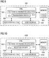
- Figures 9 and 10 provide apparatuses 900 and 1000 comprising a control circuitry (CTRL) 902, 1002, such as at least one processor, and at least one memory 904, 1004 including a computer program code (PROG), wherein the at least one memory and the computer program code (PROG), are configured, with the at least one processor, to cause the respective apparatus 900, 1000 to carry out any one of the embodiments described.
- CTRL control circuitry
- PROG computer program code
- Figures 9 and 10 show only the elements and functional entities required for understanding a processing systems of the apparatuses. Other components have been omitted for reasons of simplicity. It is apparent to a person skilled in the art that the apparatuses may also comprise other functions and structures.
- Each of the apparatuses 900, 1000 may, as said, comprise a control circuitry 902, 1002, respectively, e.g. a chip, a processor, a micro controller, or a combination of such circuitries causing the respective apparatus to perform any of the embodiments of the invention.
- Each control circuitry may be implemented with a separate digital signal processor provided with suitable software embedded on a computer readable medium, or with a separate logic circuit, such as an application specific integrated circuit (ASIC).
- ASIC application specific integrated circuit
- Each of the control circuitries may comprise an interface, such as computer port, for providing communication capabilities.
- the respective memory 904, 1004 may store software (PROG) executable by the corresponding at least one control circuitry
- the apparatuses 900, 1000 may further comprise radio interface components (TRX) 906, 1006 providing the apparatus with radio communication capabilities with the radio access network.
- TRX radio interface components
- the radio interface components may comprise standard well-known components such as amplifier, filter, frequency-converter, (de)modulator, and encoder/decoder circuitries and one or more antennas.
- the apparatuses 900, 1000 may also comprise user interfaces 908, 1008 comprising, for example, at least one keypad, a microphone, a touch display, a display, a speaker, etc. Each user interface may be used to control the respective apparatus by the user.
- the apparatuses 900, 1000 may comprise the memories 904, 1004 connected to the respective control circuitry 902, 1002.
- memory may also be integrated to the respective control circuitry and, thus, no memory may be required.
- the memory may be implemented using any suitable data storage technology, such as semiconductor based memory devices, flash memory, magnetic memory devices and systems, optical memory devices and systems, fixed memory and removable memory.
- the apparatus 900, 1000 may comprise the terminal device of a cellular communication system, e.g. a computer (PC), a laptop, a tabloid computer, a cellular phone, a communicator, a smart phone, a palm computer, or any other communication apparatus.
- the apparatus 900, 1000 is comprised in such a terminal device.
- the apparatus 900, 1000 may be or comprise a module (to be attached to the apparatus) providing connectivity, such as a plug-in unit, an "USB dongle", or any other kind of unit.
- the unit may be installed either inside the apparatus or attached to the apparatus with a connector or even wirelessly.
- the apparatus 900, 1000 may be, comprise or be comprised in an AP, such as a wireless local area network access point or a pico area network access point. In an embodiment, the apparatus 900, 1000 may be, comprise or be comprised in a base station or a relay station.
- an AP such as a wireless local area network access point or a pico area network access point.
- the apparatus 900, 1000 may be, comprise or be comprised in a base station or a relay station.
- the apparatus 900 may be the first node, i.e. the node transmitting the specific signaling (such as the AP 100, as used in the description of some of the embodiments).
- the control circuitry 902 may comprise a TDD frame determination circuitry 910 for acquiring knowledge of the TDD frame which is to be applied.
- the circuitry 910 may determine, for example, whether the frame is to comprise an extended TX period or not.
- a transmission circuitry 912 may be for transmitting the specific signaling to the target second node(s) during the extended TX part, for example.
- the apparatus 1000 may be the second node, i.e. the node receiving the specific signaling (such as the UE 106, as used in the description of some of the embodiments).
- the control circuitry 1002 may comprise a TDD frame determination circuitry 1010 for acquiring knowledge of the TDD frame which is to be applied.
- the circuitry 1010 may determine, for example, whether the frame is to comprise the extended RX period or not.
- the circuitry 1002 may also comprise a reception circuitry 1012 for receiving the specific signaling during the extended RX part from the first node(s), for example.
- circuitry refers to all of the following: (a) hardware-only circuit implementations, such as implementations in only analog and/or digital circuitry, and (b) combinations of circuits and software (and/or firmware), such as (as applicable): (i) a combination of processor(s) or (ii) portions of processor(s)/software including digital signal processor(s), software, and memory(ies) that work together to cause an apparatus to perform various functions, and (c) circuits, such as a microprocessor(s) or a portion of a microprocessor(s), that require software or firmware for operation, even if the software or firmware is not physically present.
- This definition of 'circuitry' applies to all uses of this term in this application.
- the term 'circuitry' would also cover an implementation of merely a processor (or multiple processors) or a portion of a processor and its (or their) accompanying software and/or firmware.
- the term 'circuitry' would also cover, for example and if applicable to the particular element, a baseband integrated circuit or applications processor integrated circuit for a mobile phone or a similar integrated circuit in a server, a cellular network device, or another network device.
- the techniques and methods described herein may be implemented by various means. For example, these techniques may be implemented in hardware (one or more devices), firmware (one or more devices), software (one or more modules), or combinations thereof.
- the apparatus(es) of embodiments may be implemented within one or more application-specific integrated circuits (ASICs), digital signal processors (DSPs), digital signal processing devices (DSPDs), programmable logic devices (PLDs), field programmable gate arrays (FPGAs), processors, controllers, microcontrollers, microprocessors, other electronic units designed to perform the functions described herein, or a combination thereof.
- ASICs application-specific integrated circuits
- DSPs digital signal processors
- DSPDs digital signal processing devices
- PLDs programmable logic devices
- FPGAs field programmable gate arrays
- processors controllers, microcontrollers, microprocessors, other electronic units designed to perform the functions described herein, or a combination thereof.
- the implementation can be carried out through modules of at least one chip set
- the software codes may be stored in a memory unit and executed by processors.
- the memory unit may be implemented within the processor or externally to the processor. In the latter case, it can be communicatively coupled to the processor via various means, as is known in the art.
- the components of the systems described herein may be rearranged and/or complemented by additional components in order to facilitate the achievements of the various aspects, etc., described with regard thereto, and they are not limited to the precise configurations set forth in the given figures, as will be appreciated by one skilled in the art.
- Embodiments as described may also be carried out in the form of a computer process defined by a computer program.
- the computer program may be in source code form, object code form, or in some intermediate form, and it may be stored in some sort of carrier, which may be any entity or device capable of carrying the program.
- the computer program may be stored on a computer program distribution medium readable by a computer or a processor.
- the computer program medium may be, for example but not limited to, a record medium, computer memory, read-only memory, electrical carrier signal, telecommunications signal, and software distribution package, for example.
Landscapes
- Engineering & Computer Science (AREA)
- Signal Processing (AREA)
- Computer Networks & Wireless Communication (AREA)
- Mobile Radio Communication Systems (AREA)
- Bidirectional Digital Transmission (AREA)
Claims (15)
- Procédé comprenant :l'application, par un premier nœud fonctionnant dans une séquence d'émission/réception d'un principe de communication à l'alternât par répartition dans le temps, d'une structure de trame comprenant une fraction de transmission étendue (200), la fraction de transmission étendue (200) étant une extension vers une fraction de transmission par défaut de la séquence d'émission/réception et occupant une partie de la fraction adjacente de réception par défaut de la séquence d'émission/réception, et la fraction de transmission étendue (200) chevauchant au moins partiellement dans le domaine du temps une fraction de réception (202, RX) d'une structure de trame appliquée par au moins un second nœud opérant dans la même séquence d'émission/réception que le premier nœud au moins pendant la tranche de temps de séquence d'émission/réception affectée par l'extension, etl'action provoquant une signalisation spécifique effectuée par le premier nœud auprès du ou des seconds nœuds dans la fraction de transmission étendue (200).
- Procédé selon la revendication 1, dans lequel la fraction de réception (202, RX) en chevauchement de la structure de trame appliquée par le ou les seconds nœuds est une fraction de réception par défaut (RX) ou une fraction de réception étendue (202).
- Procédé selon l'une quelconque des revendications 1 ou 2, dans lequel le premier et le ou les seconds nœuds ne présentent pas de connexion directe de communication à l'alternât par répartition dans le temps établie entre eux.
- Procédé selon l'une quelconque des revendications 1 à 3, comprenant en outre :l'application de la structure de trame comprenant la fraction de transmission étendue (200) en fonction d'une fréquence prédéfinie pour certaines trames, etl'application d'une structure de trame duplex TDD par défaut pour d'autres trames.
- Procédé selon l'une quelconque des revendications 1 à 4, comprenant en outre :
l'action provoquant une signalisation spécifique dans la fraction de transmission étendue (200) vers une pluralité de seconds nœuds, chacun étant associé à un certain réseau (604), la fraction de transmission étendue (200) chevauchant au moins partiellement dans le domaine du temps la fraction de réception (202, RX) des structures de trames appliquées par la pluralité de seconds nœuds. - Procédé selon l'une quelconque des revendications 1 à 4, comprenant en outre :
l'action provoquant la signalisation spécifique dans la fraction de transmission étendue (200) vers au moins un élément parmi les suivants : une pluralité de seconds nœuds associés chacun avec une certaine cellule, un second nœud spécifique et un groupe spécifique de seconds nœuds, la fraction de transmission étendue (200) chevauchant au moins partiellement dans le domaine du temps la fraction de réception (202, RX) des structures de trames appliquées par le ou les seconds nœuds correspondants recevant la signalisation. - Procédé selon l'une quelconque des revendications 1 à 6, comprenant en outre :l'acquisition d'informations de la structure de trame appliquée par le ou les seconds nœuds, les informations indiquant au moins l'un des éléments suivants : la longueur de la trame, les points de commutation d'émission-réception dans le domaine du temps, le nombre de fractions de réception RX, le nombre de fractions de transmission TX, la longueur d'une période de garde, le fait que la structure de trames comprend ou non la fraction de réception RX étendue, la longueur de la fraction de réception RX par défaut/étendue, le nombre de fractions de réception RX étendues, etla détermination de la structure de trame à appliquer sur la base des informations.
- Procédé selon l'une quelconque des revendications 1 à 6, comprenant en outre :
l'action impliquant la réception, en provenance d'un réseau (604) ou d'au moins un second nœud, d'informations indiquant la structure de trame à appliquer. - Procédé selon l'une quelconque des revendications 1 à 8, dans lequel la signalisation spécifique comprend la communication d'au moins un élément parmi les suivants : la diffusion d'un signal de référence, la diffusion d'un signal de sondage, une signalisation de commande, un signal de synchronisation, une signalisation d'allocation de ressources, un accusé de réception, une séquence d'émission-réception à appliquer, le nombre de sauts dans un scénario à sauts multiples, des informations système, une signalisation de dispositif à dispositif.
- Procédé selon l'une quelconque des revendications 1 à 9, dans lequel la structure de trame appliquée par le premier nœud comprend en outre un intervalle (704B) pendant lequel d'autres nœuds peuvent transmettre la signalisation spécifique à un nœud desservi par le premier nœud.
- Procédé selon l'une quelconque des revendications 1 à 10, dans lequel la fraction de transmission étendue (200) est située dans la structure de trame pour être adjacente à une période de garde ce qui facilite ainsi la commutation entre une émission et une réception.
- Procédé comprenant :l'application, par un second nœud fonctionnant dans une séquence d'émission/réception d'un principe de communication à l'alternât par répartition dans le temps, d'une structure de trame comprenant une fraction de réception étendue (202), la fraction de réception étendue (202) étant une extension vers une fraction de réception par défaut de la séquence d'émission/réception et occupant une partie de la fraction adjacente de transmission par défaut de la séquence d'émission/réception, et la fraction de réception étendue (202) chevauchant au moins partiellement dans le domaine du temps une fraction de transmission (200, TX) d'une structure de trame appliquée par au moins un premier nœud opérant dans la même séquence d'émission/réception que le second nœud au moins pendant la tranche de temps de séquence d'émission/réception affectée par l'extension, etl'action provoquant la réception d'une signalisation spécifique en provenance du ou des premiers nœuds dans la fraction de réception étendue (202).
- Appareil comprenant :un moyen permettant d'appliquer, dans un principe de communication à l'alternât par répartition dans le temps incluant une séquence d'émission/réception, une structure de trame comprenant une fraction de transmission étendue (200), la fraction de transmission étendue (200) étant une extension vers une fraction de transmission par défaut de la séquence d'émission/réception et occupant une partie de la fraction de réception par défaut adjacente de la séquence d'émission/réception, et la fraction de transmission étendue (200) chevauchant au moins partiellement dans le domaine du temps une fraction de réception (202, RX) d'une structure de trame appliquée par au moins un second nœud opérant dans la même séquence d'émission/réception que l'appareil, au moins pendant la tranche de temps de séquence d'émission/réception affectée par l'extension, etun moyen permettant de provoquer une signalisation spécifique vers le ou les seconds nœuds dans la fraction de transmission étendue (200).
- Appareil comprenant :un moyen permettant d'appliquer, dans un principe de communication à l'alternât par répartition dans le temps incluant une séquence d'émission/réception, une structure de trame comprenant une fraction de réception étendue (202), la fraction de réception étendue (202) étant une extension vers une fraction de réception par défaut de la séquence d'émission/réception et occupant une partie de la fraction de transmission par défaut adjacente de la séquence d'émission/réception, et la fraction de réception étendue (202) chevauchant au moins partiellement dans le domaine du temps une fraction de transmission (200, TX) d'une structure de trame appliquée par au moins un premier nœud opérant dans la même séquence d'émission/réception que l'appareil, au moins pendant la tranche de temps de séquence d'émission/réception affectée par l'extension, etun moyen permettant de provoquer la réception d'une signalisation spécifique en provenance du ou des premiers nœuds dans la fraction de réception étendue (202).
- Produit de programme informatique intégré sur un support de distribution pouvant être lu par un ordinateur et comprenant des instructions de programmation qui, lorsqu'elles sont chargées dans un appareil, exécutent le procédé conforme à l'une quelconque des revendications 1 à 12.
Applications Claiming Priority (1)
| Application Number | Priority Date | Filing Date | Title |
|---|---|---|---|
| PCT/EP2012/068400 WO2014056517A1 (fr) | 2012-09-19 | 2012-09-19 | Signalisation dans un système de communication tdd |
Publications (2)
| Publication Number | Publication Date |
|---|---|
| EP2898610A1 EP2898610A1 (fr) | 2015-07-29 |
| EP2898610B1 true EP2898610B1 (fr) | 2020-10-28 |
Family
ID=46880716
Family Applications (1)
| Application Number | Title | Priority Date | Filing Date |
|---|---|---|---|
| EP12761614.2A Active EP2898610B1 (fr) | 2012-09-19 | 2012-09-19 | Signalisation dans un système de communication tdd |
Country Status (7)
| Country | Link |
|---|---|
| US (1) | US9628252B2 (fr) |
| EP (1) | EP2898610B1 (fr) |
| JP (1) | JP6084693B2 (fr) |
| KR (1) | KR101644922B1 (fr) |
| CN (1) | CN104641574B (fr) |
| IN (1) | IN2015DN01892A (fr) |
| WO (1) | WO2014056517A1 (fr) |
Families Citing this family (11)
| Publication number | Priority date | Publication date | Assignee | Title |
|---|---|---|---|---|
| WO2014111154A1 (fr) | 2013-01-18 | 2014-07-24 | Nokia Solutions And Networks Oy | Découverte dans un système de communications |
| CN107005981B (zh) * | 2014-11-24 | 2021-01-22 | 瑞典爱立信有限公司 | 在所确定的第三时频资源集合中的传输和接收 |
| WO2016085383A1 (fr) | 2014-11-24 | 2016-06-02 | Telefonaktiebolaget Lm Ericsson (Publ) | Utilisation d'une technique de modulation multiporteuse précodée dans un réseau de communication sans fil |
| CN106341774B (zh) * | 2015-07-10 | 2020-03-20 | 华为技术有限公司 | 一种数据传输方法、网络设备及用户设备 |
| US10439791B2 (en) * | 2015-08-11 | 2019-10-08 | Kyocera Corporation | Time division duplex (TDD) communication configuration for unconnected base stations |
| WO2017082650A1 (fr) * | 2015-11-10 | 2017-05-18 | 엘지전자 주식회사 | Procédé et dispositif d'émission/réception de signaux associés à un changement de capacité de tx/rx dans un système fdr |
| CN107820263B (zh) * | 2016-09-13 | 2020-07-21 | 北京佰才邦技术有限公司 | 一种信息配置方法及装置 |
| JP6602813B2 (ja) * | 2017-04-24 | 2019-11-06 | 株式会社東芝 | 通信中継システム及び方法 |
| FI20185326A1 (en) * | 2018-04-06 | 2019-10-07 | Nokia Technologies Oy | Monitoring in wireless backhaul networks |
| US10700775B2 (en) | 2018-05-11 | 2020-06-30 | At&T Intellectual Property I, L.P. | Resource coordination for integrated access and backhaul |
| US20210385858A1 (en) * | 2020-06-04 | 2021-12-09 | Qualcomm Incorporated | Random access procedure selection by an integrated access and backhaul node |
Family Cites Families (14)
| Publication number | Priority date | Publication date | Assignee | Title |
|---|---|---|---|---|
| US7346103B2 (en) * | 2003-03-03 | 2008-03-18 | Interdigital Technology Corporation | Multi user detection using equalization and successive interference cancellation |
| KR100712344B1 (ko) | 2003-05-15 | 2007-05-02 | 텔레폰악티에볼라겟엘엠에릭슨(펍) | 무선 중계 네트워크에서의 간섭 소거 |
| US8411621B2 (en) * | 2005-10-27 | 2013-04-02 | Qualcomm Incorporated | Method and apparatus of processing non-sticky assignments in wireless communication systems |
| GB2440985A (en) * | 2006-08-18 | 2008-02-20 | Fujitsu Ltd | Wireless multi-hop communication system |
| CN101370160B (zh) * | 2007-08-13 | 2011-12-21 | 电信科学技术研究院 | 一种tfci信息的调制方法及装置 |
| US8310961B2 (en) * | 2007-10-08 | 2012-11-13 | Nokia Siemens Networks Oy | Techniques for link utilization for half-duplex and full-duplex stations in a wireless network |
| CN101425839B (zh) * | 2007-10-31 | 2011-09-14 | 电信科学技术研究院 | 一种确定数据发送偏移量的方法、系统和装置 |
| KR20110044892A (ko) * | 2008-08-27 | 2011-05-02 | 교세라 가부시키가이샤 | 무선중계국, 무선중계방법, 무선통신시스템, 위치관리장치, 무선단말 및 무선통신방법 |
| KR101520697B1 (ko) * | 2008-08-29 | 2015-05-21 | 엘지전자 주식회사 | 릴레이 시스템을 지원하기 위한 제어정보 전송방법 |
| KR101738162B1 (ko) * | 2009-04-10 | 2017-05-22 | 엘지전자 주식회사 | 무선 통신 시스템에서 포지셔닝 참조 신호 전송 방법 및 장치 |
| US8897235B2 (en) * | 2009-12-18 | 2014-11-25 | Qualcomm Incorporated | Protection of broadcast signals in heterogeneous networks |
| US20130272174A1 (en) * | 2010-12-20 | 2013-10-17 | Lg Electronics Inc. | Method and device for configuring frames for device cooperation in wireless communication system |
| WO2013149651A1 (fr) | 2012-04-03 | 2013-10-10 | Nokia Siemens Networks Oy | Format de trame en communications |
| US9197376B2 (en) * | 2012-08-03 | 2015-11-24 | Broadcom Corporation | Transmission time interval (TTI) bundling operation within communication systems |
-
2012
- 2012-09-19 JP JP2015532307A patent/JP6084693B2/ja active Active
- 2012-09-19 WO PCT/EP2012/068400 patent/WO2014056517A1/fr active Application Filing
- 2012-09-19 IN IN1892DEN2015 patent/IN2015DN01892A/en unknown
- 2012-09-19 EP EP12761614.2A patent/EP2898610B1/fr active Active
- 2012-09-19 CN CN201280075884.6A patent/CN104641574B/zh active Active
- 2012-09-19 US US14/427,923 patent/US9628252B2/en active Active
- 2012-09-19 KR KR1020157009763A patent/KR101644922B1/ko active IP Right Grant
Non-Patent Citations (1)
| Title |
|---|
| None * |
Also Published As
| Publication number | Publication date |
|---|---|
| JP6084693B2 (ja) | 2017-02-22 |
| CN104641574B (zh) | 2018-06-15 |
| KR20150058376A (ko) | 2015-05-28 |
| US20150256319A1 (en) | 2015-09-10 |
| EP2898610A1 (fr) | 2015-07-29 |
| KR101644922B1 (ko) | 2016-08-02 |
| IN2015DN01892A (fr) | 2015-08-07 |
| JP2015534757A (ja) | 2015-12-03 |
| US9628252B2 (en) | 2017-04-18 |
| CN104641574A (zh) | 2015-05-20 |
| WO2014056517A1 (fr) | 2014-04-17 |
Similar Documents
| Publication | Publication Date | Title |
|---|---|---|
| EP2898610B1 (fr) | Signalisation dans un système de communication tdd | |
| CN109565852B (zh) | 具有无线回程的无线网络中的动态资源分配 | |
| US10687353B2 (en) | Management of conflicting scheduling commands in wireless networks | |
| CN109845324B (zh) | 用于辅助毫米波系统中的定向同步的方法和装置 | |
| CN109479312B (zh) | 一种在无线网络中协调信令和资源分配的方法、装置和计算机可读介质 | |
| JP6472440B2 (ja) | 無線基地局、ユーザ端末および無線通信システム | |
| US10440722B2 (en) | Mobile communications network, methods, base station, relay node and communications terminal | |
| KR20170127443A (ko) | 밀리미터파 네트워크들에서의 무선 백홀과 액세스 통신들 사이의 리소스 파티셔닝 | |
| WO2020095458A1 (fr) | Terminal utilisateur et procédé de communication sans fil | |
| KR101733630B1 (ko) | 동작 모드에 대한 정보에 기초하여 스케줄링 기간들을 구성하기 위한 방법 및 장치 | |
| WO2011124015A1 (fr) | Procédé et appareil de gestion du brouillage entre cellules pour communications de dispositif à dispositif | |
| JP2020520188A (ja) | 新無線におけるページング信号と同期信号との多重化 | |
| CN110870370A (zh) | 在随机接入期间对波束对链路的配置 | |
| EP3101927A1 (fr) | Terminal d'utilisateur, station de base sans fil, procédé de communications sans fil et système de communications sans fil | |
| CN115039443B (zh) | 一种通信方法及通信装置 | |
| CN105684539B (zh) | 用户终端、无线基站以及无线通信方法 | |
| US20230224765A1 (en) | Method and device for group handover in communication system | |
| JP2021503774A (ja) | キャリア管理のための技法および装置 | |
| WO2024045304A1 (fr) | Procédé et dispositif de communication de liaison latérale | |
| US11576137B2 (en) | Synchronization signal block (SSB) configuration for power management | |
| EP3114892B1 (fr) | Configuration de terminaux sans fil sur la base de la découverte d'autres terminaux sans fil dans le voisinage à l'aide de communications à courte portée | |
| CN118104163A (zh) | 终端装置、网络装置及其方法 | |
| CN115942486A (zh) | 一种通信方法及通信装置 | |
| KR20160054396A (ko) | 비면허 대역을 통한 데이터 전송 방법 및 장치 |
Legal Events
| Date | Code | Title | Description |
|---|---|---|---|
| PUAI | Public reference made under article 153(3) epc to a published international application that has entered the european phase |
Free format text: ORIGINAL CODE: 0009012 |
|
| 17P | Request for examination filed |
Effective date: 20150420 |
|
| AK | Designated contracting states |
Kind code of ref document: A1 Designated state(s): AL AT BE BG CH CY CZ DE DK EE ES FI FR GB GR HR HU IE IS IT LI LT LU LV MC MK MT NL NO PL PT RO RS SE SI SK SM TR |
|
| AX | Request for extension of the european patent |
Extension state: BA ME |
|
| DAX | Request for extension of the european patent (deleted) | ||
| STAA | Information on the status of an ep patent application or granted ep patent |
Free format text: STATUS: EXAMINATION IS IN PROGRESS |
|
| 17Q | First examination report despatched |
Effective date: 20180514 |
|
| RAP1 | Party data changed (applicant data changed or rights of an application transferred) |
Owner name: NOKIA SOLUTIONS AND NETWORKS OY |
|
| GRAP | Despatch of communication of intention to grant a patent |
Free format text: ORIGINAL CODE: EPIDOSNIGR1 |
|
| STAA | Information on the status of an ep patent application or granted ep patent |
Free format text: STATUS: GRANT OF PATENT IS INTENDED |
|
| INTG | Intention to grant announced |
Effective date: 20200528 |
|
| GRAS | Grant fee paid |
Free format text: ORIGINAL CODE: EPIDOSNIGR3 |
|
| GRAA | (expected) grant |
Free format text: ORIGINAL CODE: 0009210 |
|
| STAA | Information on the status of an ep patent application or granted ep patent |
Free format text: STATUS: THE PATENT HAS BEEN GRANTED |
|
| AK | Designated contracting states |
Kind code of ref document: B1 Designated state(s): AL AT BE BG CH CY CZ DE DK EE ES FI FR GB GR HR HU IE IS IT LI LT LU LV MC MK MT NL NO PL PT RO RS SE SI SK SM TR |
|
| REG | Reference to a national code |
Ref country code: GB Ref legal event code: FG4D |
|
| REG | Reference to a national code |
Ref country code: CH Ref legal event code: EP |
|
| REG | Reference to a national code |
Ref country code: AT Ref legal event code: REF Ref document number: 1329299 Country of ref document: AT Kind code of ref document: T Effective date: 20201115 |
|
| REG | Reference to a national code |
Ref country code: DE Ref legal event code: R096 Ref document number: 602012072989 Country of ref document: DE |
|
| REG | Reference to a national code |
Ref country code: IE Ref legal event code: FG4D |
|
| REG | Reference to a national code |
Ref country code: AT Ref legal event code: MK05 Ref document number: 1329299 Country of ref document: AT Kind code of ref document: T Effective date: 20201028 |
|
| REG | Reference to a national code |
Ref country code: NL Ref legal event code: MP Effective date: 20201028 |
|
| PG25 | Lapsed in a contracting state [announced via postgrant information from national office to epo] |
Ref country code: NO Free format text: LAPSE BECAUSE OF FAILURE TO SUBMIT A TRANSLATION OF THE DESCRIPTION OR TO PAY THE FEE WITHIN THE PRESCRIBED TIME-LIMIT Effective date: 20210128 Ref country code: NL Free format text: LAPSE BECAUSE OF FAILURE TO SUBMIT A TRANSLATION OF THE DESCRIPTION OR TO PAY THE FEE WITHIN THE PRESCRIBED TIME-LIMIT Effective date: 20201028 Ref country code: PT Free format text: LAPSE BECAUSE OF FAILURE TO SUBMIT A TRANSLATION OF THE DESCRIPTION OR TO PAY THE FEE WITHIN THE PRESCRIBED TIME-LIMIT Effective date: 20210301 Ref country code: RS Free format text: LAPSE BECAUSE OF FAILURE TO SUBMIT A TRANSLATION OF THE DESCRIPTION OR TO PAY THE FEE WITHIN THE PRESCRIBED TIME-LIMIT Effective date: 20201028 Ref country code: FI Free format text: LAPSE BECAUSE OF FAILURE TO SUBMIT A TRANSLATION OF THE DESCRIPTION OR TO PAY THE FEE WITHIN THE PRESCRIBED TIME-LIMIT Effective date: 20201028 Ref country code: GR Free format text: LAPSE BECAUSE OF FAILURE TO SUBMIT A TRANSLATION OF THE DESCRIPTION OR TO PAY THE FEE WITHIN THE PRESCRIBED TIME-LIMIT Effective date: 20210129 |
|
| REG | Reference to a national code |
Ref country code: LT Ref legal event code: MG4D |
|
| PG25 | Lapsed in a contracting state [announced via postgrant information from national office to epo] |
Ref country code: LV Free format text: LAPSE BECAUSE OF FAILURE TO SUBMIT A TRANSLATION OF THE DESCRIPTION OR TO PAY THE FEE WITHIN THE PRESCRIBED TIME-LIMIT Effective date: 20201028 Ref country code: PL Free format text: LAPSE BECAUSE OF FAILURE TO SUBMIT A TRANSLATION OF THE DESCRIPTION OR TO PAY THE FEE WITHIN THE PRESCRIBED TIME-LIMIT Effective date: 20201028 Ref country code: SE Free format text: LAPSE BECAUSE OF FAILURE TO SUBMIT A TRANSLATION OF THE DESCRIPTION OR TO PAY THE FEE WITHIN THE PRESCRIBED TIME-LIMIT Effective date: 20201028 Ref country code: IS Free format text: LAPSE BECAUSE OF FAILURE TO SUBMIT A TRANSLATION OF THE DESCRIPTION OR TO PAY THE FEE WITHIN THE PRESCRIBED TIME-LIMIT Effective date: 20210228 Ref country code: BG Free format text: LAPSE BECAUSE OF FAILURE TO SUBMIT A TRANSLATION OF THE DESCRIPTION OR TO PAY THE FEE WITHIN THE PRESCRIBED TIME-LIMIT Effective date: 20210128 Ref country code: AT Free format text: LAPSE BECAUSE OF FAILURE TO SUBMIT A TRANSLATION OF THE DESCRIPTION OR TO PAY THE FEE WITHIN THE PRESCRIBED TIME-LIMIT Effective date: 20201028 Ref country code: ES Free format text: LAPSE BECAUSE OF FAILURE TO SUBMIT A TRANSLATION OF THE DESCRIPTION OR TO PAY THE FEE WITHIN THE PRESCRIBED TIME-LIMIT Effective date: 20201028 |
|
| PG25 | Lapsed in a contracting state [announced via postgrant information from national office to epo] |
Ref country code: HR Free format text: LAPSE BECAUSE OF FAILURE TO SUBMIT A TRANSLATION OF THE DESCRIPTION OR TO PAY THE FEE WITHIN THE PRESCRIBED TIME-LIMIT Effective date: 20201028 |
|
| REG | Reference to a national code |
Ref country code: DE Ref legal event code: R097 Ref document number: 602012072989 Country of ref document: DE |
|
| PG25 | Lapsed in a contracting state [announced via postgrant information from national office to epo] |
Ref country code: RO Free format text: LAPSE BECAUSE OF FAILURE TO SUBMIT A TRANSLATION OF THE DESCRIPTION OR TO PAY THE FEE WITHIN THE PRESCRIBED TIME-LIMIT Effective date: 20201028 Ref country code: SK Free format text: LAPSE BECAUSE OF FAILURE TO SUBMIT A TRANSLATION OF THE DESCRIPTION OR TO PAY THE FEE WITHIN THE PRESCRIBED TIME-LIMIT Effective date: 20201028 Ref country code: LT Free format text: LAPSE BECAUSE OF FAILURE TO SUBMIT A TRANSLATION OF THE DESCRIPTION OR TO PAY THE FEE WITHIN THE PRESCRIBED TIME-LIMIT Effective date: 20201028 Ref country code: CZ Free format text: LAPSE BECAUSE OF FAILURE TO SUBMIT A TRANSLATION OF THE DESCRIPTION OR TO PAY THE FEE WITHIN THE PRESCRIBED TIME-LIMIT Effective date: 20201028 Ref country code: EE Free format text: LAPSE BECAUSE OF FAILURE TO SUBMIT A TRANSLATION OF THE DESCRIPTION OR TO PAY THE FEE WITHIN THE PRESCRIBED TIME-LIMIT Effective date: 20201028 Ref country code: SM Free format text: LAPSE BECAUSE OF FAILURE TO SUBMIT A TRANSLATION OF THE DESCRIPTION OR TO PAY THE FEE WITHIN THE PRESCRIBED TIME-LIMIT Effective date: 20201028 |
|
| PG25 | Lapsed in a contracting state [announced via postgrant information from national office to epo] |
Ref country code: DK Free format text: LAPSE BECAUSE OF FAILURE TO SUBMIT A TRANSLATION OF THE DESCRIPTION OR TO PAY THE FEE WITHIN THE PRESCRIBED TIME-LIMIT Effective date: 20201028 |
|
| PLBE | No opposition filed within time limit |
Free format text: ORIGINAL CODE: 0009261 |
|
| STAA | Information on the status of an ep patent application or granted ep patent |
Free format text: STATUS: NO OPPOSITION FILED WITHIN TIME LIMIT |
|
| 26N | No opposition filed |
Effective date: 20210729 |
|
| PG25 | Lapsed in a contracting state [announced via postgrant information from national office to epo] |
Ref country code: AL Free format text: LAPSE BECAUSE OF FAILURE TO SUBMIT A TRANSLATION OF THE DESCRIPTION OR TO PAY THE FEE WITHIN THE PRESCRIBED TIME-LIMIT Effective date: 20201028 Ref country code: IT Free format text: LAPSE BECAUSE OF FAILURE TO SUBMIT A TRANSLATION OF THE DESCRIPTION OR TO PAY THE FEE WITHIN THE PRESCRIBED TIME-LIMIT Effective date: 20201028 |
|
| PG25 | Lapsed in a contracting state [announced via postgrant information from national office to epo] |
Ref country code: SI Free format text: LAPSE BECAUSE OF FAILURE TO SUBMIT A TRANSLATION OF THE DESCRIPTION OR TO PAY THE FEE WITHIN THE PRESCRIBED TIME-LIMIT Effective date: 20201028 |
|
| REG | Reference to a national code |
Ref country code: CH Ref legal event code: PL |
|
| REG | Reference to a national code |
Ref country code: BE Ref legal event code: MM Effective date: 20210930 |
|
| GBPC | Gb: european patent ceased through non-payment of renewal fee |
Effective date: 20210919 |
|
| PG25 | Lapsed in a contracting state [announced via postgrant information from national office to epo] |
Ref country code: IS Free format text: LAPSE BECAUSE OF FAILURE TO SUBMIT A TRANSLATION OF THE DESCRIPTION OR TO PAY THE FEE WITHIN THE PRESCRIBED TIME-LIMIT Effective date: 20210228 Ref country code: MC Free format text: LAPSE BECAUSE OF FAILURE TO SUBMIT A TRANSLATION OF THE DESCRIPTION OR TO PAY THE FEE WITHIN THE PRESCRIBED TIME-LIMIT Effective date: 20201028 |
|
| PG25 | Lapsed in a contracting state [announced via postgrant information from national office to epo] |
Ref country code: LU Free format text: LAPSE BECAUSE OF NON-PAYMENT OF DUE FEES Effective date: 20210919 Ref country code: IE Free format text: LAPSE BECAUSE OF NON-PAYMENT OF DUE FEES Effective date: 20210919 Ref country code: GB Free format text: LAPSE BECAUSE OF NON-PAYMENT OF DUE FEES Effective date: 20210919 Ref country code: FR Free format text: LAPSE BECAUSE OF NON-PAYMENT OF DUE FEES Effective date: 20210930 Ref country code: BE Free format text: LAPSE BECAUSE OF NON-PAYMENT OF DUE FEES Effective date: 20210930 |
|
| PG25 | Lapsed in a contracting state [announced via postgrant information from national office to epo] |
Ref country code: LI Free format text: LAPSE BECAUSE OF NON-PAYMENT OF DUE FEES Effective date: 20210930 Ref country code: CH Free format text: LAPSE BECAUSE OF NON-PAYMENT OF DUE FEES Effective date: 20210930 |
|
| PG25 | Lapsed in a contracting state [announced via postgrant information from national office to epo] |
Ref country code: HU Free format text: LAPSE BECAUSE OF FAILURE TO SUBMIT A TRANSLATION OF THE DESCRIPTION OR TO PAY THE FEE WITHIN THE PRESCRIBED TIME-LIMIT; INVALID AB INITIO Effective date: 20120919 Ref country code: CY Free format text: LAPSE BECAUSE OF FAILURE TO SUBMIT A TRANSLATION OF THE DESCRIPTION OR TO PAY THE FEE WITHIN THE PRESCRIBED TIME-LIMIT Effective date: 20201028 |
|
| PGFP | Annual fee paid to national office [announced via postgrant information from national office to epo] |
Ref country code: DE Payment date: 20230802 Year of fee payment: 12 |
|
| PG25 | Lapsed in a contracting state [announced via postgrant information from national office to epo] |
Ref country code: MK Free format text: LAPSE BECAUSE OF FAILURE TO SUBMIT A TRANSLATION OF THE DESCRIPTION OR TO PAY THE FEE WITHIN THE PRESCRIBED TIME-LIMIT Effective date: 20201028 |