EP2898560B1 - Systems and methods for bypassing fuel cells - Google Patents
Systems and methods for bypassing fuel cells Download PDFInfo
- Publication number
- EP2898560B1 EP2898560B1 EP13838378.1A EP13838378A EP2898560B1 EP 2898560 B1 EP2898560 B1 EP 2898560B1 EP 13838378 A EP13838378 A EP 13838378A EP 2898560 B1 EP2898560 B1 EP 2898560B1
- Authority
- EP
- European Patent Office
- Prior art keywords
- fuel cell
- jumper
- stack
- interconnect
- fuel
- Prior art date
- Legal status (The legal status is an assumption and is not a legal conclusion. Google has not performed a legal analysis and makes no representation as to the accuracy of the status listed.)
- Active
Links
Images




Classifications
-
- H—ELECTRICITY
- H01—ELECTRIC ELEMENTS
- H01M—PROCESSES OR MEANS, e.g. BATTERIES, FOR THE DIRECT CONVERSION OF CHEMICAL ENERGY INTO ELECTRICAL ENERGY
- H01M8/00—Fuel cells; Manufacture thereof
- H01M8/04—Auxiliary arrangements, e.g. for control of pressure or for circulation of fluids
- H01M8/04223—Auxiliary arrangements, e.g. for control of pressure or for circulation of fluids during start-up or shut-down; Depolarisation or activation, e.g. purging; Means for short-circuiting defective fuel cells
- H01M8/04246—Short circuiting means for defective fuel cells
-
- H—ELECTRICITY
- H01—ELECTRIC ELEMENTS
- H01M—PROCESSES OR MEANS, e.g. BATTERIES, FOR THE DIRECT CONVERSION OF CHEMICAL ENERGY INTO ELECTRICAL ENERGY
- H01M8/00—Fuel cells; Manufacture thereof
- H01M8/04—Auxiliary arrangements, e.g. for control of pressure or for circulation of fluids
- H01M8/04298—Processes for controlling fuel cells or fuel cell systems
- H01M8/04313—Processes for controlling fuel cells or fuel cell systems characterised by the detection or assessment of variables; characterised by the detection or assessment of failure or abnormal function
- H01M8/04664—Failure or abnormal function
- H01M8/04671—Failure or abnormal function of the individual fuel cell
-
- H—ELECTRICITY
- H01—ELECTRIC ELEMENTS
- H01M—PROCESSES OR MEANS, e.g. BATTERIES, FOR THE DIRECT CONVERSION OF CHEMICAL ENERGY INTO ELECTRICAL ENERGY
- H01M8/00—Fuel cells; Manufacture thereof
- H01M8/04—Auxiliary arrangements, e.g. for control of pressure or for circulation of fluids
- H01M8/04298—Processes for controlling fuel cells or fuel cell systems
- H01M8/04694—Processes for controlling fuel cells or fuel cell systems characterised by variables to be controlled
- H01M8/04955—Shut-off or shut-down of fuel cells
-
- H—ELECTRICITY
- H01—ELECTRIC ELEMENTS
- H01M—PROCESSES OR MEANS, e.g. BATTERIES, FOR THE DIRECT CONVERSION OF CHEMICAL ENERGY INTO ELECTRICAL ENERGY
- H01M8/00—Fuel cells; Manufacture thereof
- H01M8/24—Grouping of fuel cells, e.g. stacking of fuel cells
- H01M8/241—Grouping of fuel cells, e.g. stacking of fuel cells with solid or matrix-supported electrolytes
- H01M8/2425—High-temperature cells with solid electrolytes
- H01M8/243—Grouping of unit cells of tubular or cylindrical configuration
-
- H—ELECTRICITY
- H01—ELECTRIC ELEMENTS
- H01M—PROCESSES OR MEANS, e.g. BATTERIES, FOR THE DIRECT CONVERSION OF CHEMICAL ENERGY INTO ELECTRICAL ENERGY
- H01M8/00—Fuel cells; Manufacture thereof
- H01M8/24—Grouping of fuel cells, e.g. stacking of fuel cells
- H01M8/2465—Details of groupings of fuel cells
-
- H—ELECTRICITY
- H01—ELECTRIC ELEMENTS
- H01M—PROCESSES OR MEANS, e.g. BATTERIES, FOR THE DIRECT CONVERSION OF CHEMICAL ENERGY INTO ELECTRICAL ENERGY
- H01M8/00—Fuel cells; Manufacture thereof
- H01M8/24—Grouping of fuel cells, e.g. stacking of fuel cells
- H01M8/2465—Details of groupings of fuel cells
- H01M8/2484—Details of groupings of fuel cells characterised by external manifolds
-
- H—ELECTRICITY
- H01—ELECTRIC ELEMENTS
- H01M—PROCESSES OR MEANS, e.g. BATTERIES, FOR THE DIRECT CONVERSION OF CHEMICAL ENERGY INTO ELECTRICAL ENERGY
- H01M8/00—Fuel cells; Manufacture thereof
- H01M8/10—Fuel cells with solid electrolytes
- H01M8/12—Fuel cells with solid electrolytes operating at high temperature, e.g. with stabilised ZrO2 electrolyte
- H01M2008/1293—Fuel cells with solid oxide electrolytes
-
- Y—GENERAL TAGGING OF NEW TECHNOLOGICAL DEVELOPMENTS; GENERAL TAGGING OF CROSS-SECTIONAL TECHNOLOGIES SPANNING OVER SEVERAL SECTIONS OF THE IPC; TECHNICAL SUBJECTS COVERED BY FORMER USPC CROSS-REFERENCE ART COLLECTIONS [XRACs] AND DIGESTS
- Y02—TECHNOLOGIES OR APPLICATIONS FOR MITIGATION OR ADAPTATION AGAINST CLIMATE CHANGE
- Y02E—REDUCTION OF GREENHOUSE GAS [GHG] EMISSIONS, RELATED TO ENERGY GENERATION, TRANSMISSION OR DISTRIBUTION
- Y02E60/00—Enabling technologies; Technologies with a potential or indirect contribution to GHG emissions mitigation
- Y02E60/30—Hydrogen technology
- Y02E60/50—Fuel cells
Definitions
- Fuel cells are electrochemical devices which can convert energy stored in fuels to electrical energy with high efficiencies.
- High temperature fuel cells include solid oxide and molten carbonate fuel cells. These fuel cells may operate using hydrogen and/or hydrocarbon fuels.
- an oxidizing flow is passed through the cathode side of the fuel cell while a fuel flow is passed through the anode side of the fuel cell.
- the oxidizing flow is typically air, while the fuel flow is typically a hydrogen-rich gas created by reforming a hydrocarbon fuel source.
- the fuel cell operating at a typical temperature between 750°C and 950°C, enables the transport of negatively charged oxygen ions from the cathode flow stream to the anode flow stream, where the ion combines with either free hydrogen or hydrogen in a hydrocarbon molecule to form water vapor and/or with carbon monoxide to form carbon dioxide.
- the excess electrons from the negatively charged ion are routed back to the cathode side of the fuel cell through an electrical circuit completed between anode and cathode, resulting in an electrical current flow through the circuit.
- Fuel cell stacks may be either internally or externally manifolded for fuel and air.
- internally manifolded stacks the fuel and air is distributed to each cell using risers contained within the stack. In other words, the gas flows through openings or holes in the supporting layer of each fuel cell, such as the electrolyte layer, and gas separator of each cell.
- externally manifolded stacks the stack is open on the fuel and air inlet and outlet sides, and the fuel and air are introduced and collected independently of the stack hardware. For example, the inlet and outlet fuel and air flow in separate channels between the stack and the manifold housing in which the stack is located.
- Fuel cell stacks are frequently built from a multiplicity of cells in the form of planar elements, tubes, or other geometries. Fuel and air has to be provided to the electrochemically active surface, which can be large.
- One component of a fuel cell stack is the so called gas flow separator (referred to as a gas flow separator plate in a planar stack) that separates the individual cells in the stack.
- the gas flow separator plate separates fuel, such as hydrogen or a hydrocarbon fuel, flowing to the fuel electrode (i.e., anode) of one cell in the stack from oxidant, such as air, flowing to the air electrode (i.e., cathode) of an adjacent cell in the stack.
- the gas flow separator plate is also used as an interconnect which electrically connects the fuel electrode of one cell to the air electrode of the adjacent cell.
- the gas flow separator plate which functions as an interconnect is made of or contains an electrically conductive material.
- JPS63226884 discloses a fuel cell in which cells are sandwiched between a cathode and an anode and an oxidizing gas is supplied to the cathode side and a fuel gas is supplied to the anode side to generate electric power, wherein an instrumentation terminal plate projects from an end portion of each of the separators of the respective stages and the upper and lower instrumentation terminal plates are joined to form a bypass line.
- JP,2003-109651 ,A discloses a generating cell which placed a fuel electrode layer and an air electrode layer at both sides of a solid electrolyte layer, wherein a fuel electrode collector is arranged on the outside of the aforementioned fuel electrode layer, and an air pole charge collector is arranged on the outside of the aforementioned air electrode layer. Further disclosed is a repair method for short-circuiting a separator of damaged generating cell both sides electrically by a conductive member when damage arises in the aforementioned generating cell.
- Embodiment methods for bypassing a fuel cell in a fuel cell stack include identifying a fuel cell to bypass and connecting a conductive bypass, by welding a jumper to a side of the fuel cell stack such that the jumper is configured to electrically bypass the identified fuel cell.
- the invention refers to a method for bypassing a fuel cell in a solid oxide fuel cell stack, comprising: identifying a defective fuel cell to bypass; and welding on a side of the stack a conductive jumper to the fuel cell stack such that the jumper electrically connects a first interconnect in the fuel cell stack and a second interconnect in the fuel cell stack and electrically bypasses the identified defective fuel cell, wherein the jumper comprises a strip of metal that electrically connects the first and second interconnects and does not comprise a diode.
- the invention further refers to a solid oxide fuel cell stack device comprising: a plurality of fuel cells and a plurality of interconnects, wherein: at least one of the plurality of fuel cells comprises a defective fuel cell located between a first interconnect and a second interconnect; a jumper welded on a side of the stack and to the first and the second interconnects disposed on opposing sides of the defective fuel cell, such that the jumper electrically connects the first interconnect and the second interconnect and electrically bypasses the defective fuel cell, wherein, no jumpers are connected to the stack between each two adjacent interconnects of the plurality of the interconnects that are separated by a non-defective fuel cell of the plurality of the fuel cells, and the jumper comprises a strip of metal that electrically connects the first and second interconnects and does not comprise a diode.
- FIG. 1 illustrates a solid oxide fuel cell (SOFC) stack in which each SOFC 1 comprises a cathode electrode 3 (e.g., LSM or other conductive perovskites), a solid oxide electrolyte 5 (e.g., YSZ, ScSZ, or doped ceria), and an anode electrode 7 (e.g., a cermet such as a nickel-stabilized zirconia and/or doped ceria cermet).
- a cathode electrode 3 e.g., LSM or other conductive perovskites
- a solid oxide electrolyte 5 e.g., YSZ, ScSZ, or doped ceria
- an anode electrode 7 e.g., a cermet such as a nickel-stabilized zirconia and/or doped ceria cermet.
- the anode electrode may comprise a cermet comprising a nickel containing phase and a ceramic phase.
- the nickel containing phase may consist entirely of nickel in a reduced state. This phase may form nickel oxide when it is in an oxidized state.
- the anode electrode is preferably annealed in a reducing atmosphere prior to operation to reduce the nickel oxide to nickel.
- the nickel containing phase may include other metals in additional to nickel and/or nickel alloys.
- the ceramic phase may comprise a stabilized zirconia, such as yttria and/or scandia stabilized zirconia and/or a doped ceria, such as gadolinia, yttria and/or samaria doped ceria.
- a stabilized zirconia such as yttria and/or scandia stabilized zirconia and/or a doped ceria, such as gadolinia, yttria and/or samaria doped ceria.
- the electrolyte may comprise a stabilized zirconia, such as scandia stabilized zirconia (SSZ) or yttria stabilized zirconia (YSZ).
- SSZ scandia stabilized zirconia
- YSZ yttria stabilized zirconia
- the electrolyte may comprise another ionically conductive material, such as a doped ceria.
- the cathode electrode may comprise an electrically conductive material, such as an electrically conductive perovskite material, such as lanthanum strontium manganite (LSM). Other conductive perovskites, such as LSCo, etc., or metals, such as Pt, may also be used.
- the cathode electrode may also contain a ceramic phase similar to the anode electrode.
- the electrodes and the electrolyte may each comprise one or more sublayers of one or more of the above described materials.
- Fuel cell stacks are frequently built from a multiplicity of SOFC's 1 in the form of planar elements, tubes, or other geometries. Although the fuel cell stack in FIG. 1 is vertically oriented, fuel cell stacks may be oriented horizontally or in any other direction. Fuel and air may be provided to the electrochemically active surface, which can be large.
- the gas flow separator 9 (referred to as a gas flow separator plate when part of a planar stack), containing gas flow passages or channels 8 between ribs 10, separates the individual cells in the stack.
- the gas flow separator plate separates fuel, such as a hydrocarbon fuel, flowing to the fuel electrode (i.e. anode 7) of one cell in the stack from oxidant, such as air, flowing to the air electrode (i.e. cathode 3) of an adjacent cell in the stack.
- fuel electrode i.e. anode 7
- oxidant such as air
- the gas flow separator plate 9 is also used as an interconnect which electrically connects the anode or fuel electrode 7 of one cell to the cathode or air electrode 3 of the adjacent cell.
- the gas flow separator plate which functions as an interconnect is made of or contains electrically conductive material.
- FIG. 1 shows that the lower SOFC 1 is located between two interconnects 9.
- Interconnects may be made of or may contain electrically conductive material, such as a metal alloy (e.g., chromium-iron alloy) or an electrically conductive ceramic material, which optionally has a similar coefficient of thermal expansion to that of the solid oxide electrolyte in the cells (e.g., a difference of 0-10%).
- An electrically conductive contact layer such as a nickel contact layer, may be provided between the anode electrode and the interconnect.
- Another optional electrically conductive contact layer may be provided between the cathode electrode and the interconnect.
- the plurality of fuel cells in a fuel cell stack may share a common fuel inlet and exhaust passages or risers.
- a fuel cell stack may include a distinct electrical entity which contains two end plates on opposite ends of the stack which are connected to power conditioning equipment and the power (i.e., electricity) output of the stack.
- the electrical power output from such a distinct electrical entity may be controlled separately from other stacks.
- multiple stacks may share the same end plates.
- the stacks may jointly comprise a distinct electrical entity.
- a fuel cell stack may be part of a larger fuel cell system for generating power.
- the fuel cell stack may be located in a hot zone within such a system. During normal operation, this hot zone may operate at a high temperature, such as a temperature of about 600°C or more, e.g., 600-1000°C, such as 750-950°C.
- Fuel cells typically act as voltage sources in the system. However, fuel cells may have failure modes wherein the fuel cell becomes a defective cell and a resistive parasitic load. For example, failure of a fuel cell may occur if the fuel cell becomes cracked or otherwise damaged. Failed or underperforming fuel cells may be bypassed to avoid voltage losses.
- the various embodiments provide systems and methods for bypassing defective fuel cells in a fuel cell stack.
- FIG. 2A illustrates a cross sectional view of a fuel cell stack 200 with a defective fuel cell 1a bypassed according to an embodiment.
- the fuel cell stack 200 includes fuel cells 1 comprising cathode electrodes 3, electrolytes 5, and anode electrodes 7.
- the fuel cells 1 are connected in series by interconnects 9.
- An electrically insulating seal 102 may surround the fuel cell 1 on plural sides between the interconnects 9.
- the interconnects 9 may include cathode gas flow passages 208 that may provide air to corresponding cathode electrodes 3.
- FIG. 2A illustrates a cross sectional such that the cathode flow passages 208 may be seen above the fuel cells 1.
- Anode flow passages are not shown in FIG. 2A , but may run on opposite side of each interconnect adjacent to the anode electrode 7 and parallel (or perpendicular in alternative embodiment) to the cathode gas flow passages 208.
- the anode flow passages may be internally manifolded such that the anode flow passages do not extend through to the side of the stack 200 while the air passages may be externally manifolded.
- Jumpers 202 are attached to the fuel cell stack 200 to bypass a defective fuel cell 1. As shown in FIG. 2A , the jumpers 202 may be attached to interconnects 9a and 9b on either side of the fuel cell 1a. Jumpers 202 are attached by welding, or spot welding for electrically connecting the jumpers 202 to the interconnects 9. However, there are no jumpers (or other bypass conductors) positioned adjacent to non-defective cells in the stack, such that interconnects that sandwich a non-defective cell are not connected by a jumper or another bypass conductor.
- the jumper 202 may provide an alternate low resistance path for current and thereby bypass the fuel cell 1a between the interconnects 9a, 9b to which the jumper 202 is attached. Current would normally travel through fuel cells 1 and interconnects 9 in series. However, a jumper 202 electrically connected to two interconnects 9a, 9b places the jumper 202 in parallel with the fuel cell la between the two interconnects 9a, 9b. If the fuel cell 1a is a failed or underperforming fuel cell that is acting as a resistive parasitic load, current may travel through the low resistance jumper 202 instead of the fuel cell la and thereby avoid voltage losses.
- Fuel cell stacks may be modified with multiple jumpers 202.
- FIG. 2A illustrates two jumpers 202 on opposite sides of the fuel cell stack 200 to bypass the same fuel cell 1a. Alternate embodiments may use one or more jumpers 202 to bypass a fuel cell 1. In further embodiments, a fuel cell stack may have multiple jumpers 202 attached in order to bypass more than one fuel cell.
- FIG. 2B illustrates a fuel cell stack 250 with extended jumpers 254. Extended jumpers 254 may electrically connect nonadjacent interconnects 9c, 9d and thereby bypass fuel cells 1b and 1c in between the nonadjacent interconnects 9c, 9d.
- FIG. 3 illustrates an embodiment method 300 for bypassing a fuel cell in a fuel cell stack.
- One or more fuel cells in the fuel cell stack may be identified to be bypassed in step 302.
- a fuel cell 1 that had failed or was underperforming e.g., the fuel cell was not producing enough power, had cracked, or was not meeting any other standard
- Fuel cells and fuel cell stacks may be monitored with a variety of sensor devices, such as voltage, current or pressure probes, to determine if a fuel cell was failing or underperformed.
- a connection site for a jumper may be prepared in step 304. This step may be optional if the fuel cell stack does not need preparation. If the fuel cell stack does need preparation, a jumper connection site may be prepared, such as by removing material or coating (e.g., perovskite coating) from interconnects 9 on the side of the stack. For example, platinum, nickel, Inconel, or lanthanum strontium manganite (LSM) may be removed from the side of the fuel cell stack. Material or coating, such a perovskite coating, may be removed using a gas laser, such as a CO 2 laser in the 10,000 nm peak wavelength range using a laser ablation process. Removing material may provide better contact between the interconnects 9 and the jumper 202, 254 and facilitate welding or spot welding the jumper 202, 254 to bare metal base material.
- material or coating e.g., perovskite coating
- LSM lanthanum strontium manganite
- a jumper is welded to the fuel cell stack in step 306.
- the jumper 202, 254 may be welded to two interconnects 9, such as shown in FIG. 2A , and thereby electrically bypass a fuel cell 1 identified in step 302.
- welding the jumper 202, 254 comprises spot welding the jumper 202, 254 to a first interconnect and a second interconnect of the fuel cell stack.
- welding the jumper 202, 254 may comprise laser welding the jumper to a first interconnect and a second interconnect of the fuel cell stack.
- the jumper may be welded to the interconnects with a YbAG, NdAG, or YAG laser.
- jumpers may vary in composition.
- the jumper comprises a strip of metal.
- the jumper's material may be selected to match the coefficient of thermal expansion of other portions of the fuel cell stack to prevent uneven expansion and breakage during operation.
- the jumper may also vary in size and shape, such as being attached to multiple sides of the fuel cell stack or being attached to multiple interconnects.
- the jumper may be configured to electrically bypass multiple fuel cells.
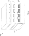
- FIG. 4 illustrates a fuel cell stack 400 with fuel cells 1 comprising cathode electrodes 3, electrolytes 5, and anode electrodes 7.
- the fuel cells 1 are connected in series by interconnects 9 with cathode gas flow passages 208 that may provide air to corresponding cathode electrodes 3.
- FIG. 4 present a front perspective view rather than a cross sectional view like FIGS. 2A and 2B so the insulating seal 102 surrounding the fuel cell 1 may be visible on all sides.
- the cathode gas flow passages 208 may extend through the front on the stack, such as if the cathode gas flow passages 208 are externally manifolded.
- the cathode gas flow passages 208 corresponding to fuel cell 1 to be bypassed may be sealed with sealing material 418.
- the sealing material 418 may comprise different materials, such as a glass or composite metal mixtures.
- the sealing material 418 may comprise lanthanum-strontium-manganate, manganese-cobalt mixtures, or alumina paste compositions.
- the sealing material may be selected to match the coefficient of thermal expansion of other portions of the fuel cell stack to prevent uneven expansion and breakage during operation.
- FIG. 5 illustrates an embodiment method 500 for sealing gas flow passages 208 and bypassing a fuel cell in a fuel cell stack.
- One or more fuel cells in the fuel cell stack may be identified to be bypassed in step 502.
- Defective fuel cells may act as large voltage drops, and therefore it may be advantageous to identify and bypass defective fuel cells. For example, a fuel cell that had failed or was underperforming (e.g., the fuel cell was not producing enough voltage, had cracked, or was not meeting any other standard) or was suspected of failing or underperforming could be identified to be bypassed.
- Fuel cells and fuel cell stacks may be monitored with a variety of sensor devices, such as voltage or pressure probes, to determine if a fuel cell was failing or underperformed.
- a connection site for a jumper may be prepared in step 504. This step may be optional if the fuel cell stack does not need preparation. If the fuel cell stack does need preparation, a jumper connection site may be prepared, such as by removing material from the side of the stack. For example, platinum, nickel, Inconel, or lanthanum strontium manganite (LSM) may be removed from the side of the fuel cell stack. Removing material may provide better contact between the interconnects 9 and the jumper 202 and facilitate welding or spot welding the jumper to bare metal base material. Preparation in step 504 may also be necessary or facilitate reaching cathode gas flow passages 208.
- LSM lanthanum strontium manganite
- the cathode gas flow passages 208 may be sealed in step 506.
- sealing material 418 may be applied to the inlets and/or outlets of the cathode gas flow passages 208 corresponding with the fuel cell identified in step 502.
- any excess sealing material from step 506 may be removed and the site may be prepared again for a jumper 202.
- a jumper 202 is welded, such as spot welded, to the fuel cell stack.
- the jumper 202 may be welded to two interconnects 9, such as shown in FIG. 4 , and thereby electrically bypass the fuel cell 1 identified in step 502.
- anode inlets and/or outlets may be sealed, or both anode and cathode inlets and/or outlets may be sealed.
- FIG. 6 illustrates a perspective cross sectional view of a fuel cell stack 600 with fuel cells 1 comprising cathode electrodes 3, electrolytes 5, and anode electrodes 7.
- the fuel cell stack 600 is shown from a different angle than in FIGS. 2A , 2B , and 4 . Instead, the cathode gas flow passages 208 run left to right and the anode gas flow passages 608 may be seen in the cross sectional view.
- the fuel cells 1 are connected in series by interconnects 9 with cathode gas flow passages 208 that may provide air to corresponding cathode electrodes 3.
- Sealing jumpers 602 may seal cathode inlets 652 and outlets 654 and also electrically connect interconnects 9g, 9h thereby bypassing fuel cell 1e.
- Systems according to further embodiments may include one or more columns, each of which may contain a plurality of fuel cell stacks (e.g., SOFC stacks).
- a fuel cell stack column may be modified with low resistance jumpers that are configured to bypass one or more entire fuel cell stack(s) in the column. Structures that may be electrically connected by such jumpers to avoid the one or more fuel cell stack(s) may vary based on the configuration of the column.
- FIG. 7A illustrates an example column 700 that contains a plurality of fuel cell stacks, such as stacks 702a, 702b, each of which may comprise a plurality of fuel cells 704 (e.g., twenty-five fuel cells).
- one or more ceramic side baffles 706 may be positioned on opposite sides of column 700 in order to direct the cathode feed into the cathode flow paths, to fill space between adjacent stacks, and to place a compressive load on the fuel cell stacks 702.
- the side baffles 706 may also electrically isolate the fuel cell stacks in column 700 from metal components in the system.
- the load on the fuel cell stacks may be provided from any one or more load sources, such as the base of the system, a block underneath the column, and/or a spring assembly above the column.
- ceramic side baffles 706 may be constructed from one or more interlocking baffle plates, which may be made from materials such as alumina or an alumina fiber/alumina matrix CMC.
- plate-shaped ceramic inserts 708 may connect baffle plate(s) to the block underneath the column, and/or the spring assembly above the column and/or to each other (if there are plural plates) to form the side baffles 706.
- the inserts 708 may fit into corresponding circular or quasi-circular cutouts in the baffle plates to increase the overall strength of the baffles 706 and/or reduce stress at the contact points between the baffle plates.
- the inserts 708 may be made of an insulator material.
- the fuel cell stacks 702 in column 700 may each contain conductive end plates 710 which function to connect the stacks 702 in series (e.g., the end plate of one stack is connected electrically to an end plate of the next stack, or one end plate is shared between adjacent stacks). Further, one or more fuel distribution manifolds 712 may be provided between adjacent fuel cell stacks. End plates can be electrically connected to one another either directly, by being placed in physical contact, or indirectly, such as through an electrically conductive fuel manifold located between the end plates.
- a jumper 714a may be formed on one side of the column 700, such as between the baffle plates that form a side baffle 706 to bypass the defective stack and is present in addition to a jumper for bypassing a defective fuel cell as defined in the claims.
- two jumpers 714a may be formed between baffle plates that form side baffles 706 on opposite sides of the column 700. In this manner, at least one jumper 714a electrically connects the end plates of non-adjacent fuel cell stacks to bypass fuel cell stack 702a.
- at least one jumper 714b may be formed in the front and/or back of column 700 to connect the exposed edges of the end plates of the fuel cell stacks located above and below fuel one or more defective cell stack(s) 702b.
- FIG. 7B illustrates another example column 750 in a fuel cell system. Similar to column 700, column 750 may contain a plurality of fuel cell stacks (e.g., stacks 702c - 702f), each of which may contain a plurality of fuel cells (e.g., 10-100, such as 25-50 fuel cells per stack). In an embodiment, one or more jumpers may be formed by electrically connecting fuel distribution manifolds 712a, 712b that exist in the column between different pairs of adjacent stacks.
- fuel cell stacks e.g., stacks 702c - 702f
- one or more jumpers may be formed by electrically connecting fuel distribution manifolds 712a, 712b that exist in the column between different pairs of adjacent stacks.
- one or more defective fuel cell stacks such as two or more underperforming or failing adjacent fuel cell stacks, such as stacks 702c, 702e
- fuel distribution manifolds 712a, 712b may have portions which protrude to the side of column 750, and one or both jumpers 714c may be formed between the protruding portions of the fuel distribution manifolds 712a, 712b on a side or opposing sides of column 750.
- At least one jumper 714d may be formed to connect the exposed edges of the electrically conductive fuel distribution manifolds 712a, 712b in the front and/or back of column 750.
- Various embodiments may implement combinations of least one jumper 714c and at least one jumper 714d.
- jumper configurations in FIGs. 7A and 7B illustrate are shown as bypassing one and two fuel cell stacks, respectively, it will be understood by those of ordinary skill in the art that any such jumpers may be implemented to bypass one or multiple adjacent fuel cell stacks based on the particular configuration of the column.
- the use of terms such as “top” and “bottom” in describing the embodiments in FIGs. 7A and 7B should be considered directional with respect to the orientation of the fuel cell stack column, as opposed to absolute direction.
- the terms “top” and “bottom” may be considered as being equivalent to the absolute directions of "left” and “right” (or vice versa).
- FIG. 8 illustrates an embodiment method 800 for sealing gas flow passages 208 and bypassing a fuel cell with the same structure.
- One or more fuel cells in the fuel cell stack may be identified to be bypassed in step 802. For example, a fuel cell that had failed or was underperforming (e.g., the fuel cell was not producing enough voltage, had cracked, or was not meeting any other standard) or was suspected of failing or underperforming could be identified to be bypassed.
- Fuel cells and fuel cell stacks may be monitored with a variety of sensor devices, such as voltage, current or pressure probes, to determine if a fuel cell was failing or underperformed.
- a site for applying a conductive sealing material to form an additional sealing jumper 602 may be prepared in step 804. This step may be optional if the fuel cell stack does not need preparation. If the fuel cell stack does need preparation, a jumper connection site may be prepared, such as by removing material from the side of the stack. For example, platinum, nickel, Inconel, or lanthanum strontium manganite (LSM) may be removed from the side of the fuel cell stack.
- LSM lanthanum strontium manganite
- a conductive sealing material may be applied to the fuel cell stack such that the conductive sealing material seals a cathode inlet or outlet of the identified fuel cell and such that the conductive sealing material electrically bypasses the identified fuel cell.
- the conductive sealing material may form a sealing jumper 602.
- Application of conductive sealing material may be performed various ways. For example, the conductive sealing material may be plasma sprayed on the fuel cell stack to connect a first interconnect and a second interconnect of the fuel cell stack.
- the conductive sealing material may include various materials.
- the conductive sealing material may include a metal alloy, an electrically conductive glass, or a composite metal mixture.
- the conductive sealing material may include lanthanum-strontium-manganate, manganese-cobalt mixtures, or alumina paste compositions.
- the conductive sealing material may be selected to match the coefficient of thermal expansion of other portions of the fuel cell stack to prevent uneven expansion and breakage during operation.
- the conductive sealing material may also be selected based on conductivity, glass transition temperature, and/or various mechanical properties to provide structural support and stability when applied to a fuel cell stack.
- anode inlets and/or outlets may be sealed, or both anode and cathode inlets and/or outlets may be sealed in step 806.
- Fuel cells 1 are electrically bypassed by one or more jumpers 202 and optionally additional conductive sealing material applied as a sealing jumper 602. These conductive bypass mechanisms may electrically bypass one or more fuel cells without need for a diode or other electrical component.
Landscapes
- Life Sciences & Earth Sciences (AREA)
- Engineering & Computer Science (AREA)
- Manufacturing & Machinery (AREA)
- Sustainable Development (AREA)
- Sustainable Energy (AREA)
- Chemical & Material Sciences (AREA)
- Chemical Kinetics & Catalysis (AREA)
- Electrochemistry (AREA)
- General Chemical & Material Sciences (AREA)
- Fuel Cell (AREA)
Description
- Fuel cells are electrochemical devices which can convert energy stored in fuels to electrical energy with high efficiencies. High temperature fuel cells include solid oxide and molten carbonate fuel cells. These fuel cells may operate using hydrogen and/or hydrocarbon fuels. There are classes of fuel cells, such as the solid oxide reversible fuel cells, that also allow reversed operation, such that water or other oxidized fuel can be reduced to unoxidized fuel using electrical energy as an input.
- In a high temperature fuel cell system, such as a solid oxide fuel cell (SOFC) system, an oxidizing flow is passed through the cathode side of the fuel cell while a fuel flow is passed through the anode side of the fuel cell. The oxidizing flow is typically air, while the fuel flow is typically a hydrogen-rich gas created by reforming a hydrocarbon fuel source. The fuel cell, operating at a typical temperature between 750°C and 950°C, enables the transport of negatively charged oxygen ions from the cathode flow stream to the anode flow stream, where the ion combines with either free hydrogen or hydrogen in a hydrocarbon molecule to form water vapor and/or with carbon monoxide to form carbon dioxide. The excess electrons from the negatively charged ion are routed back to the cathode side of the fuel cell through an electrical circuit completed between anode and cathode, resulting in an electrical current flow through the circuit.
- Fuel cell stacks may be either internally or externally manifolded for fuel and air. In internally manifolded stacks, the fuel and air is distributed to each cell using risers contained within the stack. In other words, the gas flows through openings or holes in the supporting layer of each fuel cell, such as the electrolyte layer, and gas separator of each cell. In externally manifolded stacks, the stack is open on the fuel and air inlet and outlet sides, and the fuel and air are introduced and collected independently of the stack hardware. For example, the inlet and outlet fuel and air flow in separate channels between the stack and the manifold housing in which the stack is located.
- Fuel cell stacks are frequently built from a multiplicity of cells in the form of planar elements, tubes, or other geometries. Fuel and air has to be provided to the electrochemically active surface, which can be large. One component of a fuel cell stack is the so called gas flow separator (referred to as a gas flow separator plate in a planar stack) that separates the individual cells in the stack. The gas flow separator plate separates fuel, such as hydrogen or a hydrocarbon fuel, flowing to the fuel electrode (i.e., anode) of one cell in the stack from oxidant, such as air, flowing to the air electrode (i.e., cathode) of an adjacent cell in the stack. Frequently, the gas flow separator plate is also used as an interconnect which electrically connects the fuel electrode of one cell to the air electrode of the adjacent cell. In this case, the gas flow separator plate which functions as an interconnect is made of or contains an electrically conductive material.
- When a fuel cell fails, it becomes highly resistive. In the case of a SOFC stack, operation of the stack may continue, but the voltage of the stack is increasingly consumed by the voltage drop across the resistive interface formed by the failed cell. Bypass diodes have been used in fuel cell systems to allow current to bypass the defective fuel cell, but these diodes often suffer chemical and thermal degradation inside the hot box portion of the system that operates at a temperature greater than about 600°C.
- JPS63226884 discloses a fuel cell in which cells are sandwiched between a cathode and an anode and an oxidizing gas is supplied to the cathode side and a fuel gas is supplied to the anode side to generate electric power, wherein an instrumentation terminal plate projects from an end portion of each of the separators of the respective stages and the upper and lower instrumentation terminal plates are joined to form a bypass line.
-
JP,2003-109651 - The various embodiments provide solid oxide fuel cell stack devices and methods for bypassing fuel cells in a solid oxide fuel cell stack as defined in the claims. Embodiment methods for bypassing a fuel cell in a fuel cell stack include identifying a fuel cell to bypass and connecting a conductive bypass, by welding a jumper to a side of the fuel cell stack such that the jumper is configured to electrically bypass the identified fuel cell.
- The accompanying drawings, which are incorporated herein and constitute part of this specification, illustrate example embodiments of the invention, and together with the general description given above and the detailed description given below, serve to explain the features of the invention.
-
FIG. 1 illustrates a side cross-sectional view of a SOFC stack. -
FIG. 2A illustrates a perspective cross-sectional view of a fuel cell stack with jumpers. -
FIG. 2B illustrates a perspective cross-sectional view of a fuel cell stack with extended jumpers. -
FIG. 3 is a flow diagram of an embodiment method for attaching a jumper to a fuel cell stack. -
FIG. 4 illustrates a perspective cross-sectional view of a fuel cell stack with sealed cathode gas flow passages. -
FIG. 5 is a flow diagram of an embodiment method for sealing gas flow passages and attaching a jumper to a fuel cell stack. -
FIG. 6 illustrates a front cross-sectional view of a fuel cell stack with conductive sealing material applied to seal cathode gas flow passages and bypass a fuel cell. -
FIG. 7A illustrates a perspective front view of an embodiment column of fuel cell stacks configured with jumpers connected to end plates of non-adjacent fuel cell stacks. -
FIG. 7B illustrates a side view of an embodiment column of fuel cell stacks configured with jumpers connected to two fuel distribution manifolds. -
FIG. 8 is a flow diagram of an embodiment method for applying conductive sealing material to a fuel cell stack. - The invention refers to a method for bypassing a fuel cell in a solid oxide fuel cell stack, comprising: identifying a defective fuel cell to bypass; and welding on a side of the stack a conductive jumper to the fuel cell stack such that the jumper electrically connects a first interconnect in the fuel cell stack and a second interconnect in the fuel cell stack and electrically bypasses the identified defective fuel cell, wherein the jumper comprises a strip of metal that electrically connects the first and second interconnects and does not comprise a diode. The invention further refers to a solid oxide fuel cell stack device comprising: a plurality of fuel cells and a plurality of interconnects, wherein: at least one of the plurality of fuel cells comprises a defective fuel cell located between a first interconnect and a second interconnect; a jumper welded on a side of the stack and to the first and the second interconnects disposed on opposing sides of the defective fuel cell, such that the jumper electrically connects the first interconnect and the second interconnect and electrically bypasses the defective fuel cell, wherein, no jumpers are connected to the stack between each two adjacent interconnects of the plurality of the interconnects that are separated by a non-defective fuel cell of the plurality of the fuel cells, and the jumper comprises a strip of metal that electrically connects the first and second interconnects and does not comprise a diode.
- The various embodiments will be described in detail with reference to the accompanying drawings. Wherever possible, the same reference numbers will be used throughout the drawings to refer to the same or like parts. References made to particular examples are for illustrative purposes, and are not intended to limit the scope of the invention or the claims.
-
FIG. 1 illustrates a solid oxide fuel cell (SOFC) stack in which each SOFC 1 comprises a cathode electrode 3 (e.g., LSM or other conductive perovskites), a solid oxide electrolyte 5 (e.g., YSZ, ScSZ, or doped ceria), and an anode electrode 7 (e.g., a cermet such as a nickel-stabilized zirconia and/or doped ceria cermet). - Various materials may be used for the
cathode electrode 3,electrolyte 5, andanode electrode 7. For example, the anode electrode may comprise a cermet comprising a nickel containing phase and a ceramic phase. The nickel containing phase may consist entirely of nickel in a reduced state. This phase may form nickel oxide when it is in an oxidized state. Thus, the anode electrode is preferably annealed in a reducing atmosphere prior to operation to reduce the nickel oxide to nickel. The nickel containing phase may include other metals in additional to nickel and/or nickel alloys. The ceramic phase may comprise a stabilized zirconia, such as yttria and/or scandia stabilized zirconia and/or a doped ceria, such as gadolinia, yttria and/or samaria doped ceria. - The electrolyte may comprise a stabilized zirconia, such as scandia stabilized zirconia (SSZ) or yttria stabilized zirconia (YSZ). Alternatively, the electrolyte may comprise another ionically conductive material, such as a doped ceria.
- The cathode electrode may comprise an electrically conductive material, such as an electrically conductive perovskite material, such as lanthanum strontium manganite (LSM). Other conductive perovskites, such as LSCo, etc., or metals, such as Pt, may also be used. The cathode electrode may also contain a ceramic phase similar to the anode electrode. The electrodes and the electrolyte may each comprise one or more sublayers of one or more of the above described materials.
- Fuel cell stacks are frequently built from a multiplicity of SOFC's 1 in the form of planar elements, tubes, or other geometries. Although the fuel cell stack in
FIG. 1 is vertically oriented, fuel cell stacks may be oriented horizontally or in any other direction. Fuel and air may be provided to the electrochemically active surface, which can be large. - The gas flow separator 9 (referred to as a gas flow separator plate when part of a planar stack), containing gas flow passages or
channels 8 betweenribs 10, separates the individual cells in the stack. The gas flow separator plate separates fuel, such as a hydrocarbon fuel, flowing to the fuel electrode (i.e. anode 7) of one cell in the stack from oxidant, such as air, flowing to the air electrode (i.e. cathode 3) of an adjacent cell in the stack. At either end of the stack, there may be an air end plate or fuel end plate (not shown) for providing air or fuel, respectively, to the end electrode. - Frequently, the gas
flow separator plate 9 is also used as an interconnect which electrically connects the anode orfuel electrode 7 of one cell to the cathode orair electrode 3 of the adjacent cell. In this case, the gas flow separator plate which functions as an interconnect is made of or contains electrically conductive material.FIG. 1 shows that the lower SOFC 1 is located between twointerconnects 9. - Interconnects may be made of or may contain electrically conductive material, such as a metal alloy (e.g., chromium-iron alloy) or an electrically conductive ceramic material, which optionally has a similar coefficient of thermal expansion to that of the solid oxide electrolyte in the cells (e.g., a difference of 0-10%). An electrically conductive contact layer, such as a nickel contact layer, may be provided between the anode electrode and the interconnect. Another optional electrically conductive contact layer may be provided between the cathode electrode and the interconnect.
- The plurality of fuel cells in a fuel cell stack may share a common fuel inlet and exhaust passages or risers. A fuel cell stack may include a distinct electrical entity which contains two end plates on opposite ends of the stack which are connected to power conditioning equipment and the power (i.e., electricity) output of the stack. Thus, in some configurations, the electrical power output from such a distinct electrical entity may be controlled separately from other stacks. In other embodiments, multiple stacks may share the same end plates. In this case, the stacks may jointly comprise a distinct electrical entity.
- A fuel cell stack may be part of a larger fuel cell system for generating power. The fuel cell stack may be located in a hot zone within such a system. During normal operation, this hot zone may operate at a high temperature, such as a temperature of about 600°C or more, e.g., 600-1000°C, such as 750-950°C.
- Fuel cells typically act as voltage sources in the system. However, fuel cells may have failure modes wherein the fuel cell becomes a defective cell and a resistive parasitic load. For example, failure of a fuel cell may occur if the fuel cell becomes cracked or otherwise damaged. Failed or underperforming fuel cells may be bypassed to avoid voltage losses. The various embodiments provide systems and methods for bypassing defective fuel cells in a fuel cell stack.
-
FIG. 2A illustrates a cross sectional view of afuel cell stack 200 with adefective fuel cell 1a bypassed according to an embodiment. Thefuel cell stack 200 includes fuel cells 1 comprisingcathode electrodes 3,electrolytes 5, andanode electrodes 7. The fuel cells 1 are connected in series byinterconnects 9. An electrically insulatingseal 102 may surround the fuel cell 1 on plural sides between theinterconnects 9. - The
interconnects 9 may include cathodegas flow passages 208 that may provide air tocorresponding cathode electrodes 3.FIG. 2A illustrates a cross sectional such that thecathode flow passages 208 may be seen above the fuel cells 1. Anode flow passages are not shown inFIG. 2A , but may run on opposite side of each interconnect adjacent to theanode electrode 7 and parallel (or perpendicular in alternative embodiment) to the cathodegas flow passages 208. The anode flow passages may be internally manifolded such that the anode flow passages do not extend through to the side of thestack 200 while the air passages may be externally manifolded. -
Jumpers 202 are attached to thefuel cell stack 200 to bypass a defective fuel cell 1. As shown inFIG. 2A , thejumpers 202 may be attached tointerconnects fuel cell 1a.Jumpers 202 are attached by welding, or spot welding for electrically connecting thejumpers 202 to theinterconnects 9. However, there are no jumpers (or other bypass conductors) positioned adjacent to non-defective cells in the stack, such that interconnects that sandwich a non-defective cell are not connected by a jumper or another bypass conductor. - The
jumper 202 may provide an alternate low resistance path for current and thereby bypass thefuel cell 1a between theinterconnects jumper 202 is attached. Current would normally travel through fuel cells 1 andinterconnects 9 in series. However, ajumper 202 electrically connected to twointerconnects jumper 202 in parallel with the fuel cell la between the twointerconnects fuel cell 1a is a failed or underperforming fuel cell that is acting as a resistive parasitic load, current may travel through thelow resistance jumper 202 instead of the fuel cell la and thereby avoid voltage losses. - Fuel cell stacks may be modified with
multiple jumpers 202.FIG. 2A illustrates twojumpers 202 on opposite sides of thefuel cell stack 200 to bypass thesame fuel cell 1a. Alternate embodiments may use one ormore jumpers 202 to bypass a fuel cell 1. In further embodiments, a fuel cell stack may havemultiple jumpers 202 attached in order to bypass more than one fuel cell. - In alternate embodiments, multiple fuel cells may be bypassed by a single jumper.
FIG. 2B illustrates afuel cell stack 250 withextended jumpers 254.Extended jumpers 254 may electrically connectnonadjacent interconnects fuel cells nonadjacent interconnects -
FIG. 3 illustrates anembodiment method 300 for bypassing a fuel cell in a fuel cell stack. One or more fuel cells in the fuel cell stack may be identified to be bypassed instep 302. For example, a fuel cell 1 that had failed or was underperforming (e.g., the fuel cell was not producing enough power, had cracked, or was not meeting any other standard) or was suspected of failing or underperforming could be identified as defective and to be bypassed. Fuel cells and fuel cell stacks may be monitored with a variety of sensor devices, such as voltage, current or pressure probes, to determine if a fuel cell was failing or underperformed. - A connection site for a jumper may be prepared in
step 304. This step may be optional if the fuel cell stack does not need preparation. If the fuel cell stack does need preparation, a jumper connection site may be prepared, such as by removing material or coating (e.g., perovskite coating) frominterconnects 9 on the side of the stack. For example, platinum, nickel, Inconel, or lanthanum strontium manganite (LSM) may be removed from the side of the fuel cell stack. Material or coating, such a perovskite coating, may be removed using a gas laser, such as a CO2 laser in the 10,000 nm peak wavelength range using a laser ablation process. Removing material may provide better contact between theinterconnects 9 and thejumper jumper - A jumper is welded to the fuel cell stack in
step 306. Thejumper interconnects 9, such as shown inFIG. 2A , and thereby electrically bypass a fuel cell 1 identified instep 302. In further embodiments, welding thejumper jumper jumper - In various embodiments, jumpers may vary in composition. According to the invention, the jumper comprises a strip of metal. The jumper's material may be selected to match the coefficient of thermal expansion of other portions of the fuel cell stack to prevent uneven expansion and breakage during operation. The jumper may also vary in size and shape, such as being attached to multiple sides of the fuel cell stack or being attached to multiple interconnects. In further embodiments, the jumper may be configured to electrically bypass multiple fuel cells.
- Further embodiments may include sealing a cathode inlet and/or outlet of the identified fuel cell with a sealing material.
FIG. 4 illustrates afuel cell stack 400 with fuel cells 1 comprisingcathode electrodes 3,electrolytes 5, andanode electrodes 7. The fuel cells 1 are connected in series byinterconnects 9 with cathodegas flow passages 208 that may provide air tocorresponding cathode electrodes 3.FIG. 4 present a front perspective view rather than a cross sectional view likeFIGS. 2A and2B so the insulatingseal 102 surrounding the fuel cell 1 may be visible on all sides. The cathodegas flow passages 208 may extend through the front on the stack, such as if the cathodegas flow passages 208 are externally manifolded. The cathodegas flow passages 208 corresponding to fuel cell 1 to be bypassed may be sealed with sealing material 418. - In various embodiments, the sealing material 418 may comprise different materials, such as a glass or composite metal mixtures. For example, the sealing material 418 may comprise lanthanum-strontium-manganate, manganese-cobalt mixtures, or alumina paste compositions. The sealing material may be selected to match the coefficient of thermal expansion of other portions of the fuel cell stack to prevent uneven expansion and breakage during operation.
-
FIG. 5 illustrates anembodiment method 500 for sealinggas flow passages 208 and bypassing a fuel cell in a fuel cell stack. One or more fuel cells in the fuel cell stack may be identified to be bypassed instep 502. Defective fuel cells may act as large voltage drops, and therefore it may be advantageous to identify and bypass defective fuel cells. For example, a fuel cell that had failed or was underperforming (e.g., the fuel cell was not producing enough voltage, had cracked, or was not meeting any other standard) or was suspected of failing or underperforming could be identified to be bypassed. Fuel cells and fuel cell stacks may be monitored with a variety of sensor devices, such as voltage or pressure probes, to determine if a fuel cell was failing or underperformed. - A connection site for a jumper may be prepared in
step 504. This step may be optional if the fuel cell stack does not need preparation. If the fuel cell stack does need preparation, a jumper connection site may be prepared, such as by removing material from the side of the stack. For example, platinum, nickel, Inconel, or lanthanum strontium manganite (LSM) may be removed from the side of the fuel cell stack. Removing material may provide better contact between theinterconnects 9 and thejumper 202 and facilitate welding or spot welding the jumper to bare metal base material. Preparation instep 504 may also be necessary or facilitate reaching cathodegas flow passages 208. - The cathode
gas flow passages 208 may be sealed instep 506. For example, sealing material 418 may be applied to the inlets and/or outlets of the cathodegas flow passages 208 corresponding with the fuel cell identified instep 502. Inoptional step 508, any excess sealing material fromstep 506 may be removed and the site may be prepared again for ajumper 202. - In
step 510, ajumper 202 is welded, such as spot welded, to the fuel cell stack. Thejumper 202 may be welded to twointerconnects 9, such as shown inFIG. 4 , and thereby electrically bypass the fuel cell 1 identified instep 502. In alternate embodiments, anode inlets and/or outlets may be sealed, or both anode and cathode inlets and/or outlets may be sealed. - Further embodiments may seal cathode inlets and/or outlets and bypass a fuel cell with the same structure.
FIG. 6 illustrates a perspective cross sectional view of afuel cell stack 600 with fuel cells 1 comprisingcathode electrodes 3,electrolytes 5, andanode electrodes 7. Thefuel cell stack 600 is shown from a different angle than inFIGS. 2A ,2B , and4 . Instead, the cathodegas flow passages 208 run left to right and the anodegas flow passages 608 may be seen in the cross sectional view. The fuel cells 1 are connected in series byinterconnects 9 with cathodegas flow passages 208 that may provide air tocorresponding cathode electrodes 3. Sealingjumpers 602 may sealcathode inlets 652 andoutlets 654 and also electrically connectinterconnects 9g, 9h thereby bypassing fuel cell 1e. - Systems according to further embodiments may include one or more columns, each of which may contain a plurality of fuel cell stacks (e.g., SOFC stacks). In various embodiments, a fuel cell stack column may be modified with low resistance jumpers that are configured to bypass one or more entire fuel cell stack(s) in the column. Structures that may be electrically connected by such jumpers to avoid the one or more fuel cell stack(s) may vary based on the configuration of the column.
-
FIG. 7A illustrates anexample column 700 that contains a plurality of fuel cell stacks, such asstacks column 700 in order to direct the cathode feed into the cathode flow paths, to fill space between adjacent stacks, and to place a compressive load on the fuel cell stacks 702. The side baffles 706 may also electrically isolate the fuel cell stacks incolumn 700 from metal components in the system. The load on the fuel cell stacks may be provided from any one or more load sources, such as the base of the system, a block underneath the column, and/or a spring assembly above the column. - Also in
column 700, ceramic side baffles 706 may be constructed from one or more interlocking baffle plates, which may be made from materials such as alumina or an alumina fiber/alumina matrix CMC. In some embodiments, plate-shaped ceramic inserts 708 may connect baffle plate(s) to the block underneath the column, and/or the spring assembly above the column and/or to each other (if there are plural plates) to form the side baffles 706. Theinserts 708 may fit into corresponding circular or quasi-circular cutouts in the baffle plates to increase the overall strength of thebaffles 706 and/or reduce stress at the contact points between the baffle plates. In some embodiments, theinserts 708 may be made of an insulator material. - The fuel cell stacks 702 in
column 700, for example,stacks conductive end plates 710 which function to connect the stacks 702 in series (e.g., the end plate of one stack is connected electrically to an end plate of the next stack, or one end plate is shared between adjacent stacks). Further, one or morefuel distribution manifolds 712 may be provided between adjacent fuel cell stacks. End plates can be electrically connected to one another either directly, by being placed in physical contact, or indirectly, such as through an electrically conductive fuel manifold located between the end plates. - In an embodiment, a
jumper 714a may be formed on one side of thecolumn 700, such as between the baffle plates that form aside baffle 706 to bypass the defective stack and is present in addition to a jumper for bypassing a defective fuel cell as defined in the claims. In another embodiment, twojumpers 714a may be formed between baffle plates that form side baffles 706 on opposite sides of thecolumn 700. In this manner, at least onejumper 714a electrically connects the end plates of non-adjacent fuel cell stacks to bypassfuel cell stack 702a. In another embodiment, at least onejumper 714b may be formed in the front and/or back ofcolumn 700 to connect the exposed edges of the end plates of the fuel cell stacks located above and below fuel one or more defective cell stack(s) 702b. -
FIG. 7B illustrates anotherexample column 750 in a fuel cell system. Similar tocolumn 700,column 750 may contain a plurality of fuel cell stacks (e.g., stacks 702c - 702f), each of which may contain a plurality of fuel cells (e.g., 10-100, such as 25-50 fuel cells per stack). In an embodiment, one or more jumpers may be formed by electrically connectingfuel distribution manifolds stacks fuel distribution manifold 712a (i.e., between the bottomunderperforming stack 702c andadjacent stack 702d) andfuel distribution manifold 712b (i.e., between the topunderperforming stack 702e andadjacent stack 702f) wherein said jumper is present in addition to a jumper for bypassing a defective fuel cell as defined in the claims. In an embodiment,fuel distribution manifolds column 750, and one or bothjumpers 714c may be formed between the protruding portions of thefuel distribution manifolds column 750. - In another embodiment, at least one
jumper 714d may be formed to connect the exposed edges of the electrically conductivefuel distribution manifolds column 750. Various embodiments may implement combinations of least onejumper 714c and at least onejumper 714d. - While the jumper configurations in
FIGs. 7A and7B illustrate are shown as bypassing one and two fuel cell stacks, respectively, it will be understood by those of ordinary skill in the art that any such jumpers may be implemented to bypass one or multiple adjacent fuel cell stacks based on the particular configuration of the column. Further, the use of terms such as "top" and "bottom" in describing the embodiments inFIGs. 7A and7B should be considered directional with respect to the orientation of the fuel cell stack column, as opposed to absolute direction. For example, as applied to a horizontal fuel cell stack column, the terms "top" and "bottom" may be considered as being equivalent to the absolute directions of "left" and "right" (or vice versa). -
FIG. 8 illustrates anembodiment method 800 for sealinggas flow passages 208 and bypassing a fuel cell with the same structure. One or more fuel cells in the fuel cell stack may be identified to be bypassed instep 802. For example, a fuel cell that had failed or was underperforming (e.g., the fuel cell was not producing enough voltage, had cracked, or was not meeting any other standard) or was suspected of failing or underperforming could be identified to be bypassed. Fuel cells and fuel cell stacks may be monitored with a variety of sensor devices, such as voltage, current or pressure probes, to determine if a fuel cell was failing or underperformed. - A site for applying a conductive sealing material to form an
additional sealing jumper 602 may be prepared instep 804. This step may be optional if the fuel cell stack does not need preparation. If the fuel cell stack does need preparation, a jumper connection site may be prepared, such as by removing material from the side of the stack. For example, platinum, nickel, Inconel, or lanthanum strontium manganite (LSM) may be removed from the side of the fuel cell stack. - In
step 806, a conductive sealing material may be applied to the fuel cell stack such that the conductive sealing material seals a cathode inlet or outlet of the identified fuel cell and such that the conductive sealing material electrically bypasses the identified fuel cell. The conductive sealing material may form a sealingjumper 602. Application of conductive sealing material may be performed various ways. For example, the conductive sealing material may be plasma sprayed on the fuel cell stack to connect a first interconnect and a second interconnect of the fuel cell stack. - The conductive sealing material may include various materials. For example, the conductive sealing material may include a metal alloy, an electrically conductive glass, or a composite metal mixture. In further embodiments, the conductive sealing material may include lanthanum-strontium-manganate, manganese-cobalt mixtures, or alumina paste compositions.
- The conductive sealing material may be selected to match the coefficient of thermal expansion of other portions of the fuel cell stack to prevent uneven expansion and breakage during operation. The conductive sealing material may also be selected based on conductivity, glass transition temperature, and/or various mechanical properties to provide structural support and stability when applied to a fuel cell stack. In alternate embodiments, anode inlets and/or outlets may be sealed, or both anode and cathode inlets and/or outlets may be sealed in
step 806. - Fuel cells 1 are electrically bypassed by one or
more jumpers 202 and optionally additional conductive sealing material applied as a sealingjumper 602. These conductive bypass mechanisms may electrically bypass one or more fuel cells without need for a diode or other electrical component.
Claims (8)
- A method for bypassing a fuel cell (1) in a solid oxide fuel cell stack (200/ 250/ 400/ 600/ 702a, 702b, 702c, 702d, 702e, 702f), comprising:identifying a defective fuel cell to bypass; whereinthe method is characterized bywelding on a side of the stack a conductive jumper (202/ 254/ 602) to the fuel cell stack such that the jumper electrically connects a first interconnect (9a/ 9c/ 9g) in the fuel cell stack and a second interconnect (9b/ 9d/ 9h) in the fuel cell stack and electrically bypasses the identified defective fuel cell (1), wherein the jumper comprises a strip of metal that electrically connects the first and second interconnects and does not comprise a diode.
- The method of claim 1, further comprising preparing a jumper connection site; and
wherein preparing a jumper connection site comprises using a gas laser to remove a perovskite coating from the first (9a/ 9c/ 9g) and second (9b/ 9d/ 9h) interconnect. - The method of claim 1, wherein welding the jumper (202/ 254/ 602) comprises one of:spot welding a jumper to the first interconnect (9a/ 9c/ 9g) and the second (9b/ 9d/ 9h) interconnect of the fuel cell stack; andlaser welding the jumper to the first interconnect and the second interconnect of the fuel cell stack.
- The method of claim 1, wherein the jumper (202/ 254/ 602) is configured to electrically bypass multiple fuel cells.
- The method of claim 1, further comprising at least one of:sealing a cathode inlet or outlet of the identified fuel cell with a sealing material; andsealing an anode inlet or outlet of the identified fuel cell with the sealing material.
- The method of claim 5, further comprising removing excess sealing material, wherein the sealing material comprises lanthanum-strontium-manganate, manganese-cobalt mixture, or alumina paste compositions.
- A solid oxide fuel cell stack device (200/ 250/ 400/ 600/ 702a, 702b, 702c, 702d, 702e, 702f) comprising:
a plurality of fuel cells and a plurality of interconnects (9), wherein:at least one of the plurality of fuel cells comprises a defective fuel cell (1) located between a first interconnect (9a/ 9c/ 9g) and a second interconnect; and whereinthe solid oxide fuel cell stack is characterized by
a jumper (202/ 254/ 602) welded on a side of the stack and to the first (9a/ 9c/ 9g) and the second interconnects (9b/ 9d/ 9h) disposed on opposing sides of the defective fuel cell, such that the jumper electrically connects the first interconnect and the second interconnect and electrically bypasses the defective fuel cell, wherein,no jumpers are connected to the stack between each two adjacent interconnects of the plurality of the interconnects that are separated by a non-defective fuel cell of the plurality of the fuel cells, andthe jumper comprises a strip of metal that electrically connects the first and second interconnects and does not comprise a diode. - The device of claim 7, wherein further comprising a conductive sealing material (418) that seals an inlet or outlet of a cathode or anode of the defective fuel cell while electrically connecting the first (9a/ 9c/ 9g) and the second (9b/ 9d/ 9h) interconnects.
Applications Claiming Priority (2)
| Application Number | Priority Date | Filing Date | Title |
|---|---|---|---|
| US201261703832P | 2012-09-21 | 2012-09-21 | |
| PCT/US2013/060145 WO2014047059A1 (en) | 2012-09-21 | 2013-09-17 | Systems and methods for bypassing fuel cells |
Publications (3)
| Publication Number | Publication Date |
|---|---|
| EP2898560A1 EP2898560A1 (en) | 2015-07-29 |
| EP2898560A4 EP2898560A4 (en) | 2016-05-18 |
| EP2898560B1 true EP2898560B1 (en) | 2020-04-22 |
Family
ID=50339176
Family Applications (1)
| Application Number | Title | Priority Date | Filing Date |
|---|---|---|---|
| EP13838378.1A Active EP2898560B1 (en) | 2012-09-21 | 2013-09-17 | Systems and methods for bypassing fuel cells |
Country Status (9)
| Country | Link |
|---|---|
| US (1) | US20140087286A1 (en) |
| EP (1) | EP2898560B1 (en) |
| JP (1) | JP2015534227A (en) |
| KR (1) | KR20150058260A (en) |
| CN (1) | CN104798236B (en) |
| AU (1) | AU2013318322A1 (en) |
| CA (1) | CA2885345A1 (en) |
| TW (1) | TWI595700B (en) |
| WO (1) | WO2014047059A1 (en) |
Families Citing this family (9)
| Publication number | Priority date | Publication date | Assignee | Title |
|---|---|---|---|---|
| WO2017123486A1 (en) * | 2016-01-11 | 2017-07-20 | 3M Innovative Properties Company | Computer with baffles directing and separating air flow for high cooling |
| CN108110272B (en) * | 2016-11-23 | 2021-04-30 | 中国科学院宁波材料技术与工程研究所 | High-temperature solid fuel cell pack with sealing and electron collecting integrated structure and preparation method thereof |
| US10566646B2 (en) * | 2017-08-08 | 2020-02-18 | Bloom Energy Corporation | Fuel cell stack containing external electrode for corrosion mitigation |
| CN108417875B (en) * | 2018-02-09 | 2020-07-14 | 广东国鸿氢能科技有限公司 | Distribution manifold and fuel cell stack group |
| US11271240B2 (en) * | 2019-05-28 | 2022-03-08 | Bloom Energy Corporation | Fuel cell column containing electrically insulated fuel manifold and manifold jumper |
| US11664521B2 (en) | 2020-02-18 | 2023-05-30 | Bloom Energy Corporation | Fuel cell system with electrical control of fuel utilization and method of operating thereof |
| KR20220165655A (en) | 2021-06-08 | 2022-12-15 | 블룸 에너지 코퍼레이션 | Fuel plenum and fuel cell stack including same |
| FR3128062B1 (en) * | 2021-10-11 | 2024-11-08 | Commissariat Energie Atomique | MODULE FOR ELECTROCHEMICAL DEVICE WITH INCREASED LIFE |
| SE547653C2 (en) * | 2023-07-05 | 2025-11-04 | Powercell Sweden Ab | Fuel cell stack with a malfunctioning fuel cell unit |
Citations (3)
| Publication number | Priority date | Publication date | Assignee | Title |
|---|---|---|---|---|
| JPS63226884A (en) * | 1987-03-16 | 1988-09-21 | Ishikawajima Harima Heavy Ind Co Ltd | Fuel cell |
| JP2008243751A (en) * | 2007-03-29 | 2008-10-09 | Toho Gas Co Ltd | Solid oxide fuel cell tubular single cell, solid oxide fuel cell bundle and solid oxide fuel cell module |
| WO2012170844A2 (en) * | 2011-06-09 | 2012-12-13 | Bloom Energy Corporation | Fuel cell bypass diode structures and attachment methods |
Family Cites Families (17)
| Publication number | Priority date | Publication date | Assignee | Title |
|---|---|---|---|---|
| JPS62246268A (en) * | 1986-04-18 | 1987-10-27 | Sanyo Electric Co Ltd | Method of treating defective cells in fuel cell |
| NO180176C (en) * | 1994-06-30 | 1997-02-26 | Norske Stats Oljeselskap | Power collector device for a fuel cell stack |
| DE19746616C1 (en) * | 1997-10-22 | 1999-01-21 | Forschungszentrum Juelich Gmbh | Damaged cell bridging method in fuel cell stack |
| JP3330870B2 (en) * | 1998-04-09 | 2002-09-30 | 三菱電機株式会社 | Method of treating defective cells of fuel cell |
| JP2003109651A (en) | 2001-09-28 | 2003-04-11 | Mitsubishi Materials Corp | Repair method for solid oxide fuel cell |
| US7358005B2 (en) * | 2003-09-18 | 2008-04-15 | General Electric Company | Methods and apparatus for isolating solid oxide fuel cells |
| JP2005263582A (en) * | 2004-03-19 | 2005-09-29 | Fukuoka Prefecture | Perovskite type compound thin film and method for producing the same |
| JP2006056769A (en) * | 2004-07-23 | 2006-03-02 | Nippon Sheet Glass Co Ltd | Glass composition for sealing, glass frit for sealing, and glass sheet for sealing |
| ITMI20042248A1 (en) * | 2004-11-19 | 2005-02-19 | Uhdenora Technologies Srl | BIPOLAR PLATE FOR ELECTROLYZER INCLUDING A SINGLE WALL |
| US20060246331A1 (en) * | 2005-04-29 | 2006-11-02 | Steinbroner Matthew P | Partitioned fuel cell stacks and fuel cell systems including the same |
| US8691474B2 (en) * | 2006-04-03 | 2014-04-08 | Bloom Energy Corporation | Fuel cell stack components and materials |
| US7927752B2 (en) * | 2007-03-09 | 2011-04-19 | GM Global Technology Operations LLC | Individual cell shorting during startup and shutdown using an integrated switch |
| CN100524894C (en) * | 2007-05-25 | 2009-08-05 | 中国科学院宁波材料技术与工程研究所 | Flat-plate -type solid-oxide fuel battery stack sealing method and its dedicated sealing member |
| US8617762B2 (en) * | 2007-09-28 | 2013-12-31 | General Electric Company | Method of processing a ceramic electrolyte, and related articles |
| US9059434B2 (en) * | 2008-08-06 | 2015-06-16 | Bloom Energy Corporation | Structure and method for SOFC operation with failed cell diode bypass |
| US8535836B2 (en) * | 2009-07-08 | 2013-09-17 | Bloom Energy Corporation | Method of operating a fuel cell system with bypass ports in a fuel processing assembly |
| US9120683B2 (en) * | 2010-02-08 | 2015-09-01 | Ballard Power Systems Inc. | Method and device using a ceramic bond material for bonding metallic interconnect to ceramic electrode |
-
2013
- 2013-09-17 CN CN201380060045.1A patent/CN104798236B/en not_active Expired - Fee Related
- 2013-09-17 CA CA2885345A patent/CA2885345A1/en not_active Abandoned
- 2013-09-17 EP EP13838378.1A patent/EP2898560B1/en active Active
- 2013-09-17 JP JP2015533131A patent/JP2015534227A/en active Pending
- 2013-09-17 WO PCT/US2013/060145 patent/WO2014047059A1/en not_active Ceased
- 2013-09-17 KR KR1020157007838A patent/KR20150058260A/en not_active Withdrawn
- 2013-09-17 AU AU2013318322A patent/AU2013318322A1/en not_active Abandoned
- 2013-09-17 US US14/029,178 patent/US20140087286A1/en not_active Abandoned
- 2013-09-18 TW TW102133977A patent/TWI595700B/en not_active IP Right Cessation
Patent Citations (3)
| Publication number | Priority date | Publication date | Assignee | Title |
|---|---|---|---|---|
| JPS63226884A (en) * | 1987-03-16 | 1988-09-21 | Ishikawajima Harima Heavy Ind Co Ltd | Fuel cell |
| JP2008243751A (en) * | 2007-03-29 | 2008-10-09 | Toho Gas Co Ltd | Solid oxide fuel cell tubular single cell, solid oxide fuel cell bundle and solid oxide fuel cell module |
| WO2012170844A2 (en) * | 2011-06-09 | 2012-12-13 | Bloom Energy Corporation | Fuel cell bypass diode structures and attachment methods |
Also Published As
| Publication number | Publication date |
|---|---|
| WO2014047059A1 (en) | 2014-03-27 |
| EP2898560A1 (en) | 2015-07-29 |
| TWI595700B (en) | 2017-08-11 |
| JP2015534227A (en) | 2015-11-26 |
| CA2885345A1 (en) | 2014-03-27 |
| EP2898560A4 (en) | 2016-05-18 |
| KR20150058260A (en) | 2015-05-28 |
| US20140087286A1 (en) | 2014-03-27 |
| CN104798236B (en) | 2017-03-08 |
| TW201424112A (en) | 2014-06-16 |
| CN104798236A (en) | 2015-07-22 |
| AU2013318322A1 (en) | 2015-04-09 |
Similar Documents
| Publication | Publication Date | Title |
|---|---|---|
| CN104798236B (en) | For bypassing the system and method for fuel cell | |
| US6677069B1 (en) | Sealless radial solid oxide fuel cell stack design | |
| US11271240B2 (en) | Fuel cell column containing electrically insulated fuel manifold and manifold jumper | |
| AU2001281220A1 (en) | Sealless radial solid electrolyte fuel cell stack design | |
| KR102169225B1 (en) | Electrochemical reaction single cell and electrochemical reaction cell stack | |
| JP2017010710A (en) | Electrochemical reaction unit and fuel cell stack | |
| JP7186199B2 (en) | Electrochemical reaction cell stack | |
| US9059434B2 (en) | Structure and method for SOFC operation with failed cell diode bypass | |
| US20250015314A1 (en) | Module for an electrochemical device, having a longer useful life | |
| JP2018041569A (en) | Electrochemical reaction unit and electrochemical reaction cell stack | |
| JP7213276B2 (en) | Electrochemical reaction cell stack | |
| JP2019057407A (en) | Stack connection body | |
| KR101155375B1 (en) | Combined flat-tube anode support solid oxide fuel cell and stack structure using the same | |
| JP6393714B2 (en) | Electrochemical reaction cell and electrochemical reaction cell stack | |
| JP2017010682A (en) | Interconnector fuel battery single cell composite body and fuel battery stack | |
| JP2020170631A (en) | Electrochemical reaction cell stack | |
| JP7082958B2 (en) | Electrochemical reaction cell stack | |
| JP6902511B2 (en) | Electrochemical reaction cell stack | |
| JP2018014246A (en) | Electrochemical reaction unit and electrochemical reaction cell stack | |
| JP7085314B2 (en) | Electrochemical reaction unit and electrochemical reaction cell stack | |
| JP2023045435A (en) | Electrochemical reaction cell stack | |
| KR101185379B1 (en) | Combined flat-tube anode support for solid oxide fuel cell and stack structure using the same | |
| JP2018174041A (en) | Electrochemical reaction unit and electrochemical reaction cell stack | |
| JP2017224525A (en) | Collector member-electrochemical reaction single cell composite body, and electrochemical reaction cell stack |
Legal Events
| Date | Code | Title | Description |
|---|---|---|---|
| PUAI | Public reference made under article 153(3) epc to a published international application that has entered the european phase |
Free format text: ORIGINAL CODE: 0009012 |
|
| 17P | Request for examination filed |
Effective date: 20150416 |
|
| AK | Designated contracting states |
Kind code of ref document: A1 Designated state(s): AL AT BE BG CH CY CZ DE DK EE ES FI FR GB GR HR HU IE IS IT LI LT LU LV MC MK MT NL NO PL PT RO RS SE SI SK SM TR |
|
| AX | Request for extension of the european patent |
Extension state: BA ME |
|
| DAX | Request for extension of the european patent (deleted) | ||
| RA4 | Supplementary search report drawn up and despatched (corrected) |
Effective date: 20160418 |
|
| RIC1 | Information provided on ipc code assigned before grant |
Ipc: H01M 8/124 20160101ALN20160412BHEP Ipc: H01M 8/2465 20160101ALI20160412BHEP Ipc: H01M 8/04664 20160101ALI20160412BHEP Ipc: H01M 8/04223 20160101ALI20160412BHEP Ipc: H01M 8/04955 20160101AFI20160412BHEP |
|
| STAA | Information on the status of an ep patent application or granted ep patent |
Free format text: STATUS: EXAMINATION IS IN PROGRESS |
|
| 17Q | First examination report despatched |
Effective date: 20161221 |
|
| REG | Reference to a national code |
Ref country code: DE Ref legal event code: R079 Ref document number: 602013068255 Country of ref document: DE Free format text: PREVIOUS MAIN CLASS: H01M0008040000 Ipc: H01M0008049550 |
|
| GRAP | Despatch of communication of intention to grant a patent |
Free format text: ORIGINAL CODE: EPIDOSNIGR1 |
|
| STAA | Information on the status of an ep patent application or granted ep patent |
Free format text: STATUS: GRANT OF PATENT IS INTENDED |
|
| RIC1 | Information provided on ipc code assigned before grant |
Ipc: H01M 8/2465 20160101ALI20190828BHEP Ipc: H01M 8/124 20160101ALN20190828BHEP Ipc: H01M 8/04664 20160101ALI20190828BHEP Ipc: H01M 8/04955 20160101AFI20190828BHEP Ipc: H01M 8/04223 20160101ALI20190828BHEP |
|
| RIC1 | Information provided on ipc code assigned before grant |
Ipc: H01M 8/04223 20160101ALI20190830BHEP Ipc: H01M 8/124 20160101ALN20190830BHEP Ipc: H01M 8/2465 20160101ALI20190830BHEP Ipc: H01M 8/04955 20160101AFI20190830BHEP Ipc: H01M 8/04664 20160101ALI20190830BHEP |
|
| INTG | Intention to grant announced |
Effective date: 20190916 |
|
| GRAS | Grant fee paid |
Free format text: ORIGINAL CODE: EPIDOSNIGR3 |
|
| GRAA | (expected) grant |
Free format text: ORIGINAL CODE: 0009210 |
|
| STAA | Information on the status of an ep patent application or granted ep patent |
Free format text: STATUS: THE PATENT HAS BEEN GRANTED |
|
| AK | Designated contracting states |
Kind code of ref document: B1 Designated state(s): AL AT BE BG CH CY CZ DE DK EE ES FI FR GB GR HR HU IE IS IT LI LT LU LV MC MK MT NL NO PL PT RO RS SE SI SK SM TR |
|
| REG | Reference to a national code |
Ref country code: GB Ref legal event code: FG4D |
|
| REG | Reference to a national code |
Ref country code: CH Ref legal event code: EP |
|
| REG | Reference to a national code |
Ref country code: IE Ref legal event code: FG4D |
|
| REG | Reference to a national code |
Ref country code: DE Ref legal event code: R096 Ref document number: 602013068255 Country of ref document: DE |
|
| REG | Reference to a national code |
Ref country code: AT Ref legal event code: REF Ref document number: 1261347 Country of ref document: AT Kind code of ref document: T Effective date: 20200515 |
|
| REG | Reference to a national code |
Ref country code: LT Ref legal event code: MG4D |
|
| REG | Reference to a national code |
Ref country code: NL Ref legal event code: MP Effective date: 20200422 |
|
| PG25 | Lapsed in a contracting state [announced via postgrant information from national office to epo] |
Ref country code: NO Free format text: LAPSE BECAUSE OF FAILURE TO SUBMIT A TRANSLATION OF THE DESCRIPTION OR TO PAY THE FEE WITHIN THE PRESCRIBED TIME-LIMIT Effective date: 20200722 Ref country code: GR Free format text: LAPSE BECAUSE OF FAILURE TO SUBMIT A TRANSLATION OF THE DESCRIPTION OR TO PAY THE FEE WITHIN THE PRESCRIBED TIME-LIMIT Effective date: 20200723 Ref country code: IS Free format text: LAPSE BECAUSE OF FAILURE TO SUBMIT A TRANSLATION OF THE DESCRIPTION OR TO PAY THE FEE WITHIN THE PRESCRIBED TIME-LIMIT Effective date: 20200822 Ref country code: FI Free format text: LAPSE BECAUSE OF FAILURE TO SUBMIT A TRANSLATION OF THE DESCRIPTION OR TO PAY THE FEE WITHIN THE PRESCRIBED TIME-LIMIT Effective date: 20200422 Ref country code: SE Free format text: LAPSE BECAUSE OF FAILURE TO SUBMIT A TRANSLATION OF THE DESCRIPTION OR TO PAY THE FEE WITHIN THE PRESCRIBED TIME-LIMIT Effective date: 20200422 Ref country code: NL Free format text: LAPSE BECAUSE OF FAILURE TO SUBMIT A TRANSLATION OF THE DESCRIPTION OR TO PAY THE FEE WITHIN THE PRESCRIBED TIME-LIMIT Effective date: 20200422 Ref country code: PT Free format text: LAPSE BECAUSE OF FAILURE TO SUBMIT A TRANSLATION OF THE DESCRIPTION OR TO PAY THE FEE WITHIN THE PRESCRIBED TIME-LIMIT Effective date: 20200824 Ref country code: LT Free format text: LAPSE BECAUSE OF FAILURE TO SUBMIT A TRANSLATION OF THE DESCRIPTION OR TO PAY THE FEE WITHIN THE PRESCRIBED TIME-LIMIT Effective date: 20200422 |
|
| REG | Reference to a national code |
Ref country code: AT Ref legal event code: MK05 Ref document number: 1261347 Country of ref document: AT Kind code of ref document: T Effective date: 20200422 |
|
| PG25 | Lapsed in a contracting state [announced via postgrant information from national office to epo] |
Ref country code: RS Free format text: LAPSE BECAUSE OF FAILURE TO SUBMIT A TRANSLATION OF THE DESCRIPTION OR TO PAY THE FEE WITHIN THE PRESCRIBED TIME-LIMIT Effective date: 20200422 Ref country code: BG Free format text: LAPSE BECAUSE OF FAILURE TO SUBMIT A TRANSLATION OF THE DESCRIPTION OR TO PAY THE FEE WITHIN THE PRESCRIBED TIME-LIMIT Effective date: 20200722 Ref country code: LV Free format text: LAPSE BECAUSE OF FAILURE TO SUBMIT A TRANSLATION OF THE DESCRIPTION OR TO PAY THE FEE WITHIN THE PRESCRIBED TIME-LIMIT Effective date: 20200422 Ref country code: HR Free format text: LAPSE BECAUSE OF FAILURE TO SUBMIT A TRANSLATION OF THE DESCRIPTION OR TO PAY THE FEE WITHIN THE PRESCRIBED TIME-LIMIT Effective date: 20200422 |
|
| PG25 | Lapsed in a contracting state [announced via postgrant information from national office to epo] |
Ref country code: AL Free format text: LAPSE BECAUSE OF FAILURE TO SUBMIT A TRANSLATION OF THE DESCRIPTION OR TO PAY THE FEE WITHIN THE PRESCRIBED TIME-LIMIT Effective date: 20200422 |
|
| REG | Reference to a national code |
Ref country code: DE Ref legal event code: R097 Ref document number: 602013068255 Country of ref document: DE |
|
| PG25 | Lapsed in a contracting state [announced via postgrant information from national office to epo] |
Ref country code: AT Free format text: LAPSE BECAUSE OF FAILURE TO SUBMIT A TRANSLATION OF THE DESCRIPTION OR TO PAY THE FEE WITHIN THE PRESCRIBED TIME-LIMIT Effective date: 20200422 Ref country code: EE Free format text: LAPSE BECAUSE OF FAILURE TO SUBMIT A TRANSLATION OF THE DESCRIPTION OR TO PAY THE FEE WITHIN THE PRESCRIBED TIME-LIMIT Effective date: 20200422 Ref country code: SM Free format text: LAPSE BECAUSE OF FAILURE TO SUBMIT A TRANSLATION OF THE DESCRIPTION OR TO PAY THE FEE WITHIN THE PRESCRIBED TIME-LIMIT Effective date: 20200422 Ref country code: DK Free format text: LAPSE BECAUSE OF FAILURE TO SUBMIT A TRANSLATION OF THE DESCRIPTION OR TO PAY THE FEE WITHIN THE PRESCRIBED TIME-LIMIT Effective date: 20200422 Ref country code: CZ Free format text: LAPSE BECAUSE OF FAILURE TO SUBMIT A TRANSLATION OF THE DESCRIPTION OR TO PAY THE FEE WITHIN THE PRESCRIBED TIME-LIMIT Effective date: 20200422 Ref country code: RO Free format text: LAPSE BECAUSE OF FAILURE TO SUBMIT A TRANSLATION OF THE DESCRIPTION OR TO PAY THE FEE WITHIN THE PRESCRIBED TIME-LIMIT Effective date: 20200422 Ref country code: ES Free format text: LAPSE BECAUSE OF FAILURE TO SUBMIT A TRANSLATION OF THE DESCRIPTION OR TO PAY THE FEE WITHIN THE PRESCRIBED TIME-LIMIT Effective date: 20200422 |
|
| PG25 | Lapsed in a contracting state [announced via postgrant information from national office to epo] |
Ref country code: PL Free format text: LAPSE BECAUSE OF FAILURE TO SUBMIT A TRANSLATION OF THE DESCRIPTION OR TO PAY THE FEE WITHIN THE PRESCRIBED TIME-LIMIT Effective date: 20200422 Ref country code: SK Free format text: LAPSE BECAUSE OF FAILURE TO SUBMIT A TRANSLATION OF THE DESCRIPTION OR TO PAY THE FEE WITHIN THE PRESCRIBED TIME-LIMIT Effective date: 20200422 |
|
| PLBE | No opposition filed within time limit |
Free format text: ORIGINAL CODE: 0009261 |
|
| STAA | Information on the status of an ep patent application or granted ep patent |
Free format text: STATUS: NO OPPOSITION FILED WITHIN TIME LIMIT |
|
| 26N | No opposition filed |
Effective date: 20210125 |
|
| PG25 | Lapsed in a contracting state [announced via postgrant information from national office to epo] |
Ref country code: MC Free format text: LAPSE BECAUSE OF FAILURE TO SUBMIT A TRANSLATION OF THE DESCRIPTION OR TO PAY THE FEE WITHIN THE PRESCRIBED TIME-LIMIT Effective date: 20200422 |
|
| REG | Reference to a national code |
Ref country code: CH Ref legal event code: PL |
|
| GBPC | Gb: european patent ceased through non-payment of renewal fee |
Effective date: 20200917 |
|
| PG25 | Lapsed in a contracting state [announced via postgrant information from national office to epo] |
Ref country code: SI Free format text: LAPSE BECAUSE OF FAILURE TO SUBMIT A TRANSLATION OF THE DESCRIPTION OR TO PAY THE FEE WITHIN THE PRESCRIBED TIME-LIMIT Effective date: 20200422 |
|
| REG | Reference to a national code |
Ref country code: BE Ref legal event code: MM Effective date: 20200930 |
|
| PG25 | Lapsed in a contracting state [announced via postgrant information from national office to epo] |
Ref country code: LU Free format text: LAPSE BECAUSE OF NON-PAYMENT OF DUE FEES Effective date: 20200917 |
|
| PG25 | Lapsed in a contracting state [announced via postgrant information from national office to epo] |
Ref country code: FR Free format text: LAPSE BECAUSE OF NON-PAYMENT OF DUE FEES Effective date: 20200930 |
|
| PG25 | Lapsed in a contracting state [announced via postgrant information from national office to epo] |
Ref country code: LI Free format text: LAPSE BECAUSE OF NON-PAYMENT OF DUE FEES Effective date: 20200930 Ref country code: IE Free format text: LAPSE BECAUSE OF NON-PAYMENT OF DUE FEES Effective date: 20200917 Ref country code: GB Free format text: LAPSE BECAUSE OF NON-PAYMENT OF DUE FEES Effective date: 20200917 Ref country code: BE Free format text: LAPSE BECAUSE OF NON-PAYMENT OF DUE FEES Effective date: 20200930 Ref country code: CH Free format text: LAPSE BECAUSE OF NON-PAYMENT OF DUE FEES Effective date: 20200930 |
|
| PG25 | Lapsed in a contracting state [announced via postgrant information from national office to epo] |
Ref country code: TR Free format text: LAPSE BECAUSE OF FAILURE TO SUBMIT A TRANSLATION OF THE DESCRIPTION OR TO PAY THE FEE WITHIN THE PRESCRIBED TIME-LIMIT Effective date: 20200422 Ref country code: MT Free format text: LAPSE BECAUSE OF FAILURE TO SUBMIT A TRANSLATION OF THE DESCRIPTION OR TO PAY THE FEE WITHIN THE PRESCRIBED TIME-LIMIT Effective date: 20200422 Ref country code: CY Free format text: LAPSE BECAUSE OF FAILURE TO SUBMIT A TRANSLATION OF THE DESCRIPTION OR TO PAY THE FEE WITHIN THE PRESCRIBED TIME-LIMIT Effective date: 20200422 |
|
| PG25 | Lapsed in a contracting state [announced via postgrant information from national office to epo] |
Ref country code: MK Free format text: LAPSE BECAUSE OF FAILURE TO SUBMIT A TRANSLATION OF THE DESCRIPTION OR TO PAY THE FEE WITHIN THE PRESCRIBED TIME-LIMIT Effective date: 20200422 |
|
| PGFP | Annual fee paid to national office [announced via postgrant information from national office to epo] |
Ref country code: DE Payment date: 20250929 Year of fee payment: 13 |
|
| PGFP | Annual fee paid to national office [announced via postgrant information from national office to epo] |
Ref country code: IT Payment date: 20250919 Year of fee payment: 13 |