EP2897677B1 - Contrôle d'un appareil de respiration et d'humification - Google Patents
Contrôle d'un appareil de respiration et d'humification Download PDFInfo
- Publication number
- EP2897677B1 EP2897677B1 EP13841022.0A EP13841022A EP2897677B1 EP 2897677 B1 EP2897677 B1 EP 2897677B1 EP 13841022 A EP13841022 A EP 13841022A EP 2897677 B1 EP2897677 B1 EP 2897677B1
- Authority
- EP
- European Patent Office
- Prior art keywords
- temperature
- mask
- patient
- flow
- humidity
- Prior art date
- Legal status (The legal status is an assumption and is not a legal conclusion. Google has not performed a legal analysis and makes no representation as to the accuracy of the status listed.)
- Active
Links
- 230000029058 respiratory gaseous exchange Effects 0.000 title claims description 99
- 238000000034 method Methods 0.000 claims description 21
- 230000008569 process Effects 0.000 claims description 15
- 239000000463 material Substances 0.000 claims description 2
- 239000003570 air Substances 0.000 claims 11
- 239000012080 ambient air Substances 0.000 claims 1
- XLYOFNOQVPJJNP-UHFFFAOYSA-N water Substances O XLYOFNOQVPJJNP-UHFFFAOYSA-N 0.000 description 28
- 230000006870 function Effects 0.000 description 24
- 239000007789 gas Substances 0.000 description 12
- 238000010586 diagram Methods 0.000 description 11
- 238000003062 neural network model Methods 0.000 description 11
- 230000008859 change Effects 0.000 description 7
- 239000000203 mixture Substances 0.000 description 7
- 239000012530 fluid Substances 0.000 description 5
- 238000009795 derivation Methods 0.000 description 4
- 238000004458 analytical method Methods 0.000 description 3
- 230000007423 decrease Effects 0.000 description 3
- 230000000694 effects Effects 0.000 description 3
- 238000005259 measurement Methods 0.000 description 3
- 230000007246 mechanism Effects 0.000 description 3
- 230000002093 peripheral effect Effects 0.000 description 3
- 238000002560 therapeutic procedure Methods 0.000 description 3
- 208000001705 Mouth breathing Diseases 0.000 description 2
- 238000013528 artificial neural network Methods 0.000 description 2
- 238000009792 diffusion process Methods 0.000 description 2
- 238000010438 heat treatment Methods 0.000 description 2
- 210000004072 lung Anatomy 0.000 description 2
- 238000011144 upstream manufacturing Methods 0.000 description 2
- 208000019693 Lung disease Diseases 0.000 description 1
- 230000001133 acceleration Effects 0.000 description 1
- 230000017531 blood circulation Effects 0.000 description 1
- 230000037396 body weight Effects 0.000 description 1
- 238000009833 condensation Methods 0.000 description 1
- 230000005494 condensation Effects 0.000 description 1
- 238000010276 construction Methods 0.000 description 1
- 239000013256 coordination polymer Substances 0.000 description 1
- 125000004122 cyclic group Chemical group 0.000 description 1
- 230000001419 dependent effect Effects 0.000 description 1
- 238000004836 empirical method Methods 0.000 description 1
- 230000008020 evaporation Effects 0.000 description 1
- 238000001704 evaporation Methods 0.000 description 1
- 230000036541 health Effects 0.000 description 1
- 230000036571 hydration Effects 0.000 description 1
- 238000006703 hydration reaction Methods 0.000 description 1
- 230000003993 interaction Effects 0.000 description 1
- 238000010801 machine learning Methods 0.000 description 1
- 238000013178 mathematical model Methods 0.000 description 1
- 230000003278 mimic effect Effects 0.000 description 1
- 230000001737 promoting effect Effects 0.000 description 1
- 230000036391 respiratory frequency Effects 0.000 description 1
- 210000002345 respiratory system Anatomy 0.000 description 1
- 206010039083 rhinitis Diseases 0.000 description 1
- 238000005070 sampling Methods 0.000 description 1
- 238000007789 sealing Methods 0.000 description 1
- 238000004448 titration Methods 0.000 description 1
Images


Classifications
-
- A—HUMAN NECESSITIES
- A61—MEDICAL OR VETERINARY SCIENCE; HYGIENE
- A61M—DEVICES FOR INTRODUCING MEDIA INTO, OR ONTO, THE BODY; DEVICES FOR TRANSDUCING BODY MEDIA OR FOR TAKING MEDIA FROM THE BODY; DEVICES FOR PRODUCING OR ENDING SLEEP OR STUPOR
- A61M16/00—Devices for influencing the respiratory system of patients by gas treatment, e.g. mouth-to-mouth respiration; Tracheal tubes
- A61M16/10—Preparation of respiratory gases or vapours
- A61M16/1075—Preparation of respiratory gases or vapours by influencing the temperature
- A61M16/109—Preparation of respiratory gases or vapours by influencing the temperature the humidifying liquid or the beneficial agent
-
- A—HUMAN NECESSITIES
- A61—MEDICAL OR VETERINARY SCIENCE; HYGIENE
- A61M—DEVICES FOR INTRODUCING MEDIA INTO, OR ONTO, THE BODY; DEVICES FOR TRANSDUCING BODY MEDIA OR FOR TAKING MEDIA FROM THE BODY; DEVICES FOR PRODUCING OR ENDING SLEEP OR STUPOR
- A61M16/00—Devices for influencing the respiratory system of patients by gas treatment, e.g. mouth-to-mouth respiration; Tracheal tubes
- A61M16/0003—Accessories therefor, e.g. sensors, vibrators, negative pressure
-
- A—HUMAN NECESSITIES
- A61—MEDICAL OR VETERINARY SCIENCE; HYGIENE
- A61M—DEVICES FOR INTRODUCING MEDIA INTO, OR ONTO, THE BODY; DEVICES FOR TRANSDUCING BODY MEDIA OR FOR TAKING MEDIA FROM THE BODY; DEVICES FOR PRODUCING OR ENDING SLEEP OR STUPOR
- A61M16/00—Devices for influencing the respiratory system of patients by gas treatment, e.g. mouth-to-mouth respiration; Tracheal tubes
- A61M16/06—Respiratory or anaesthetic masks
-
- A—HUMAN NECESSITIES
- A61—MEDICAL OR VETERINARY SCIENCE; HYGIENE
- A61M—DEVICES FOR INTRODUCING MEDIA INTO, OR ONTO, THE BODY; DEVICES FOR TRANSDUCING BODY MEDIA OR FOR TAKING MEDIA FROM THE BODY; DEVICES FOR PRODUCING OR ENDING SLEEP OR STUPOR
- A61M16/00—Devices for influencing the respiratory system of patients by gas treatment, e.g. mouth-to-mouth respiration; Tracheal tubes
- A61M16/10—Preparation of respiratory gases or vapours
- A61M16/14—Preparation of respiratory gases or vapours by mixing different fluids, one of them being in a liquid phase
- A61M16/16—Devices to humidify the respiration air
-
- A—HUMAN NECESSITIES
- A61—MEDICAL OR VETERINARY SCIENCE; HYGIENE
- A61M—DEVICES FOR INTRODUCING MEDIA INTO, OR ONTO, THE BODY; DEVICES FOR TRANSDUCING BODY MEDIA OR FOR TAKING MEDIA FROM THE BODY; DEVICES FOR PRODUCING OR ENDING SLEEP OR STUPOR
- A61M16/00—Devices for influencing the respiratory system of patients by gas treatment, e.g. mouth-to-mouth respiration; Tracheal tubes
- A61M16/0051—Devices for influencing the respiratory system of patients by gas treatment, e.g. mouth-to-mouth respiration; Tracheal tubes with alarm devices
-
- A—HUMAN NECESSITIES
- A61—MEDICAL OR VETERINARY SCIENCE; HYGIENE
- A61M—DEVICES FOR INTRODUCING MEDIA INTO, OR ONTO, THE BODY; DEVICES FOR TRANSDUCING BODY MEDIA OR FOR TAKING MEDIA FROM THE BODY; DEVICES FOR PRODUCING OR ENDING SLEEP OR STUPOR
- A61M16/00—Devices for influencing the respiratory system of patients by gas treatment, e.g. mouth-to-mouth respiration; Tracheal tubes
- A61M16/0057—Pumps therefor
- A61M16/0066—Blowers or centrifugal pumps
- A61M16/0069—Blowers or centrifugal pumps the speed thereof being controlled by respiratory parameters, e.g. by inhalation
-
- A—HUMAN NECESSITIES
- A61—MEDICAL OR VETERINARY SCIENCE; HYGIENE
- A61M—DEVICES FOR INTRODUCING MEDIA INTO, OR ONTO, THE BODY; DEVICES FOR TRANSDUCING BODY MEDIA OR FOR TAKING MEDIA FROM THE BODY; DEVICES FOR PRODUCING OR ENDING SLEEP OR STUPOR
- A61M16/00—Devices for influencing the respiratory system of patients by gas treatment, e.g. mouth-to-mouth respiration; Tracheal tubes
- A61M16/021—Devices for influencing the respiratory system of patients by gas treatment, e.g. mouth-to-mouth respiration; Tracheal tubes operated by electrical means
- A61M16/022—Control means therefor
- A61M16/024—Control means therefor including calculation means, e.g. using a processor
- A61M16/026—Control means therefor including calculation means, e.g. using a processor specially adapted for predicting, e.g. for determining an information representative of a flow limitation during a ventilation cycle by using a root square technique or a regression analysis
-
- A—HUMAN NECESSITIES
- A61—MEDICAL OR VETERINARY SCIENCE; HYGIENE
- A61M—DEVICES FOR INTRODUCING MEDIA INTO, OR ONTO, THE BODY; DEVICES FOR TRANSDUCING BODY MEDIA OR FOR TAKING MEDIA FROM THE BODY; DEVICES FOR PRODUCING OR ENDING SLEEP OR STUPOR
- A61M16/00—Devices for influencing the respiratory system of patients by gas treatment, e.g. mouth-to-mouth respiration; Tracheal tubes
- A61M16/10—Preparation of respiratory gases or vapours
- A61M16/1075—Preparation of respiratory gases or vapours by influencing the temperature
- A61M16/1095—Preparation of respiratory gases or vapours by influencing the temperature in the connecting tubes
-
- A—HUMAN NECESSITIES
- A61—MEDICAL OR VETERINARY SCIENCE; HYGIENE
- A61M—DEVICES FOR INTRODUCING MEDIA INTO, OR ONTO, THE BODY; DEVICES FOR TRANSDUCING BODY MEDIA OR FOR TAKING MEDIA FROM THE BODY; DEVICES FOR PRODUCING OR ENDING SLEEP OR STUPOR
- A61M16/00—Devices for influencing the respiratory system of patients by gas treatment, e.g. mouth-to-mouth respiration; Tracheal tubes
- A61M16/10—Preparation of respiratory gases or vapours
- A61M16/14—Preparation of respiratory gases or vapours by mixing different fluids, one of them being in a liquid phase
- A61M16/16—Devices to humidify the respiration air
- A61M16/161—Devices to humidify the respiration air with means for measuring the humidity
-
- A—HUMAN NECESSITIES
- A61—MEDICAL OR VETERINARY SCIENCE; HYGIENE
- A61M—DEVICES FOR INTRODUCING MEDIA INTO, OR ONTO, THE BODY; DEVICES FOR TRANSDUCING BODY MEDIA OR FOR TAKING MEDIA FROM THE BODY; DEVICES FOR PRODUCING OR ENDING SLEEP OR STUPOR
- A61M16/00—Devices for influencing the respiratory system of patients by gas treatment, e.g. mouth-to-mouth respiration; Tracheal tubes
- A61M16/0003—Accessories therefor, e.g. sensors, vibrators, negative pressure
- A61M2016/003—Accessories therefor, e.g. sensors, vibrators, negative pressure with a flowmeter
- A61M2016/0033—Accessories therefor, e.g. sensors, vibrators, negative pressure with a flowmeter electrical
- A61M2016/0039—Accessories therefor, e.g. sensors, vibrators, negative pressure with a flowmeter electrical in the inspiratory circuit
-
- A—HUMAN NECESSITIES
- A61—MEDICAL OR VETERINARY SCIENCE; HYGIENE
- A61M—DEVICES FOR INTRODUCING MEDIA INTO, OR ONTO, THE BODY; DEVICES FOR TRANSDUCING BODY MEDIA OR FOR TAKING MEDIA FROM THE BODY; DEVICES FOR PRODUCING OR ENDING SLEEP OR STUPOR
- A61M16/00—Devices for influencing the respiratory system of patients by gas treatment, e.g. mouth-to-mouth respiration; Tracheal tubes
- A61M16/0003—Accessories therefor, e.g. sensors, vibrators, negative pressure
- A61M2016/003—Accessories therefor, e.g. sensors, vibrators, negative pressure with a flowmeter
- A61M2016/0033—Accessories therefor, e.g. sensors, vibrators, negative pressure with a flowmeter electrical
- A61M2016/0042—Accessories therefor, e.g. sensors, vibrators, negative pressure with a flowmeter electrical in the expiratory circuit
-
- A—HUMAN NECESSITIES
- A61—MEDICAL OR VETERINARY SCIENCE; HYGIENE
- A61M—DEVICES FOR INTRODUCING MEDIA INTO, OR ONTO, THE BODY; DEVICES FOR TRANSDUCING BODY MEDIA OR FOR TAKING MEDIA FROM THE BODY; DEVICES FOR PRODUCING OR ENDING SLEEP OR STUPOR
- A61M2205/00—General characteristics of the apparatus
- A61M2205/33—Controlling, regulating or measuring
- A61M2205/3331—Pressure; Flow
- A61M2205/3334—Measuring or controlling the flow rate
-
- A—HUMAN NECESSITIES
- A61—MEDICAL OR VETERINARY SCIENCE; HYGIENE
- A61M—DEVICES FOR INTRODUCING MEDIA INTO, OR ONTO, THE BODY; DEVICES FOR TRANSDUCING BODY MEDIA OR FOR TAKING MEDIA FROM THE BODY; DEVICES FOR PRODUCING OR ENDING SLEEP OR STUPOR
- A61M2205/00—General characteristics of the apparatus
- A61M2205/33—Controlling, regulating or measuring
- A61M2205/3368—Temperature
-
- A—HUMAN NECESSITIES
- A61—MEDICAL OR VETERINARY SCIENCE; HYGIENE
- A61M—DEVICES FOR INTRODUCING MEDIA INTO, OR ONTO, THE BODY; DEVICES FOR TRANSDUCING BODY MEDIA OR FOR TAKING MEDIA FROM THE BODY; DEVICES FOR PRODUCING OR ENDING SLEEP OR STUPOR
- A61M2205/00—General characteristics of the apparatus
- A61M2205/50—General characteristics of the apparatus with microprocessors or computers
- A61M2205/502—User interfaces, e.g. screens or keyboards
-
- A—HUMAN NECESSITIES
- A61—MEDICAL OR VETERINARY SCIENCE; HYGIENE
- A61M—DEVICES FOR INTRODUCING MEDIA INTO, OR ONTO, THE BODY; DEVICES FOR TRANSDUCING BODY MEDIA OR FOR TAKING MEDIA FROM THE BODY; DEVICES FOR PRODUCING OR ENDING SLEEP OR STUPOR
- A61M2230/00—Measuring parameters of the user
- A61M2230/50—Temperature
Definitions
- the present invention relates to humidification breathing apparatus and their control to provide humidified air to a patient at a desired humidity and temperature
- the intention is to provide humidified air to the patient at a desired humidity and/or temperature to achieve the desired patient comfort and/or therapy.
- Providing the desired humidity and/or temperature requires achieving and maintaining the humidity and/or temperature of humidified air at the patient (that is, in the vicinity of the patient's mouth and/or nose) as this is the humidity and temperature of air that is ultimately passed to the patient. (NB: "in the vicinity” can also be termed “at or near” or “proximate”.)
- this involves heating and/or humidifying air that passes through the flow path of the breathing apparatus from the flow generator to the patient (via e.g. the conduit and patient interface) until the desired humidity and/or temperature proximate the patient is achieved and maintained.
- a target temperature and/or humidity is determined for a particular point (such as the humidifier outlet or the end of the conduit/hose), and it is that temperature and/or humidity that is controlled.
- the difficulty with this approach is that achieving and maintaining the target temperature and/or humidity at the point in the flow path does not guarantee that the desired humidity and/or temperature are achieved proximate to the patient and delivered to them.
- the humidity and/or temperature of humidified air can change by the time it reaches the patient. For example, if the temperature and/or humidity of air at the end of the conduit is kept at a target, the humidity and temperature fluctuations provided in the patient interface mean that the actual temperature and/or humidity delivered to the patient via the patient interface varies in a unknown manner from that at the end of the hose. This makes it difficult to know the actual temperature/humidity of air at the patient and makes it difficult to deliver the desired temperature and/or humidity of humidified air to the patient.
- US 2010/275919 discloses a respiratory system that includes: a mask body adapted for attachment to a user's face; a gas supplier connected to the mask body to supply a gas to the mask body; a central control unit associated with the gas supplier to control temperature and humidity of the gas supplied from the gas supplier to the mask body; a sensor unit disposed in the mask body to produce sensing signals and to convert the sensing signals into a signal output that is related ot at least temperature and humidity of the gas; and a transmitting unit to transmit the signal output to the central control unit.
- the temperature and humidity of the gas supplied from the gas supplier is controlled based on the signal output.
- US 2010/294279 A1 discloses a system with a temperature and humidity controller which adjusts the temperature and humidity to achieve a desired temperature. It measures exhaled temperature and uses a feedback loop to control the parameters.
- the present invention provides a humidification breathing apparatus as claimed.
- the present invention relates to a humidification breathing apparatus for supplying humidified air to a patient.
- the humidification breathing apparatus could be a humidifier on its own, or a humidifier combined with other hardware to provide additional breathing assistance, such as a CPAP (continuous positive airway pressure) apparatus, Auto titration apparatus, bi-level apparatus or other PAP apparatus operating at e.g. 3to 20cm H 2 O or similar or high flow breathing apparatus with a humidifier.
- the humidification breathing apparatus and its method of operation generates and delivers humidified air to a patient at (also deemed to mean "or close to") a desired humidity and/or temperature.
- the humidification breathing apparatus and its method of operation aim to achieve a desired humidity and/or temperature of the humidified air is that actually delivered to the patient. That is, the humidification breathing apparatus and method of operation control the humidity and/or temperature of humidified air in the air flow path such that the humidified air proximate/proximal (that is at or near) the patient is at the desired humidity and/
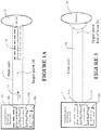
- the humidification breathing apparatus has air humidification capabilities (box 10), comprising a humidifier for humidification 10a, flow generator 10b and controller 10c, along with hardware for other capabilities such as CPAP or the like.
- a flow path 11 delivers humidified air 13 to the patient 12.
- the flow path is shown separate to the breathing apparatus box 10, but it can be considered part of the breathing apparatus, and the flow path can include parts of the hardware itself, such as internal ducting and air paths within the humidifier.
- the patient interface can also be considered part of the flow path and humidification breathing apparatus in general.
- the temperature and/or humidity of humidified air 13 is controlled at some point (target point) 14 in the humidification breathing apparatus flow path.
- Models of the downstream contributions 15 to humidity and/or temperature provided by components and inputs (e.g. patient inputs) further down the remaining parts of the flow path (ending at the patient) are determined and target temperature/humidity models are devised and implemented in the controller 10c.
- a target temperature and/or humidity at the target point is determined from the models. This target temperature and/or humidity is determined using the models such that if the target temperature and/or humidity is reached, the remaining contributions 15 to humidity and temperature from downstream influences bring the actual temperature and/or humidity proximate the patient to (or close to) the desired values.
- the humidification breathing apparatus and/or any peripheral components are operated to control the humidity and/or temperature of humidified air passing through the humidification breathing apparatus flow path so that the target temperature and/or humidity at the target point are achieved and maintained.
- the target temperature and/or humidity of the air in the flow path can be achieved using any of the usual control methods for a humidification breathing apparatus, such as using closed loop feedback (using sensors or the like) or using models or other predictive mechanisms.
- humidification breathing apparatus control 18 is provided to achieve the required desired temperature and humidity at the patient.
- the control comprises (parameter) models 16 for determining relevant values of parameters that must be achieved to deliver the desired temperature and humidity at the patient, and control functionality (e.g. in the form of models/equations) 17 to operate the humidification apparatus to achieve those parameter values.
- the models comprise patient contribution/target parameter models 16, and humidification breathing apparatus control models for e.g. controlling the apparatus heater plate temperature and breathing tube heater power.
- the humidification breathing apparatus control 18 among other things uses ambient temperature 19a, user settings 19b, ambient humidity 19c, and patient feedback comprising patient flow 19f, patient temperature 19d, patient humidity 19e.
- Control output parameters 20, signals or other control mechanisms are output 20, such as heater plate temperature 20a and heated breathing tube power 20b, which are used to control the humidification breathing apparatus operation to achieve the desired temperature and humidity at the patient.
- the relevant model(s) in effect takes into account the contribution of the patient to the humidity and temperature of the humidified air.
- the contribution may be due, for example, to the temperature and/or humidity of the patient breath and also breath flow characteristics (also termed "flow” or "patient flow” or “flow characteristics”).
- Other parameters can optionally be used also, including those relating to the mask type itself.
- a parameter(s) could comprise mask internal volume, mask surface area, and/or mask material.
- the controller 109 can calculate the required target temperature and/or humidity of the air at some other point in the air flow path which if achieved will achieve the desired parameters of humidified air at/delivered to the patient.
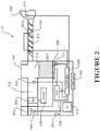
- FIG. 2 A possible non-limiting embodiment of a humidification breathing apparatus is shown in overview in Figures 2 to 4 .
- it is a CPAP apparatus 1 with integrated humidifier as shown in Figure 2 .
- any sort of breathing apparatus that provides humidification could be used, including a flow therapy apparatus with humidification or even a humidifier alone.
- FIG. 2 shows a block diagram illustrating one embodiment of a humidification breathing apparatus 1, comprising a PAP apparatus 100 for delivering a supply of breathing gases, a breathing conduit 101, which comprises a heater, and a patient interface 102.
- the breathing conduit 101 (also called a “hose” or “tube”) extends from an outlet in the PAP apparatus 100 and to the patient interface 102.
- the patient interface may be any suitable sealing patient interface such as a full face mask, nasal mask, direct nasal mask, oral mask or the like, with bias flow holes for a bias flow rate that is kept constant during both the inhalation and exhalation phases by maintaining constant pressure at the mask.
- the PAP apparatus comprises a blower 103.
- the blower preferably comprises a fan driven by an electric motor. Air is drawn into the PAP apparatus through the inlet 104 by the fan. Pressurised air leaves the fan for supply to the patient.
- controllable flow generators may draw on a source of high pressure gas, and regulate a flow of gas from the high pressure source.
- the PAP apparatus comprises a humidifier 115.
- the humidifier 115 may be separate from the PAP apparatus and part of the PAP apparatus.
- the humidifier 115 as shown is a pass over type humidifier where air passing through the humidifier picks up a quantity of water vapour from a reservoir of water 107. The water reservoir is heated by a heater 108.
- the humidifier is preferably integrated into the housing of the PAP apparatus.
- the humidifier may be a separate component within the housing of the PAP apparatus or separate from the PAP apparatus with a conduit connecting between the PAP apparatus and the humidifier.
- Other types of humidifiers, other than a pass over type may be used. In some forms multiple humidifiers may used.
- the humidified air leaves the end of heated breathing tube 101 (later referred as end of hose, EOH), it is mixed with the patients' exhaled breathe and then flows out of the bias hole on a nasal, full face or oral mask 102.
- EOH end of hose
- a non heated breathing tube could be used instead.
- the PAP apparatus comprises a controller 109.
- the controller 109 is used to control the humidification breathing apparatus, including the PAP apparatus, tube heater 101a, and other peripherals. It also operates the model(s) of the present invention.
- the controller receives inputs from a user interface (UI) 113 and sensors.
- UI user interface
- the user interface could be in the form of any suitable user interface such as a knob, a plurality of buttons, a screen or any combination thereof.
- the user interface allows the PAP apparatus to display information to the user and also allows a user to input information to the PAP apparatus, more particularly to the controller.
- the controller may also be provided with an interface 114 for connecting to an external data source.
- the controller comprises inputs for receiving inputs from one or more sensors (such as 112, 110, 201, 111, 117, 119 as shown), which can comprise temperature, flow, humidity and/or pressure sensors upstream or downstream to the fan or outside the apparatus.
- a flow sensor determines the flow characteristics (such as volume, velocity or phase) of gases supplied to the patient or user.
- the flow sensor may be positioned upstream 110 or downstream 111, 112 to the fan.
- Ambient temperature and humidity sensors 201, 110 can also be used - which can be at the blower inlet, humidifier inlet or any other suitable location.
- end of hose 112 and/or mask 117 temperature and/or humidity sensors can be used as required.
- a heater plate temperature sensor 119 is used.
- the sensors shown are one configuration of sensors that can be used. Any other configuration of sensors and any other types of sensors may be used. There may be fewer or more sensors than those shown. Sensors can be provided in any suitable location to sense any of flow, humidity, temperature and/or pressure or the like of the patient (e.g. patient exhaled flow measured in the mask or at any other suitable point), humidified or unhumidified flow at any point in the flow path, ambient surroundings or at any other point in the apparatus or peripheral components.
- the apparatus is powered by a power supply.
- the humidification breathing apparatus comprises an air flow path 30, which can comprise any part in which air 13 flow travels. That can comprise the blower inlet, the blower 103, ducting to the humidifier 118, flow path through the water chamber 115, outlet ducts from the water chamber, the conduit 101 and the patient interface 102.
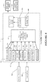
- the desired temperature and humidity is that in the mask near the patient's nose/mouth - this is the temperature and humidity that will be delivered to the patient.
- the target point is a suitable point in that air flow path, which in this embodiment is the end of the conduit (termed "end of hose" 31 see Figure 3 ), as this is a point in the flow path in which humidity and/or temperature can be controlled to a target value.
- the patient interface is a full face, nasal or oral mask.
- the mask 102 itself and the patient provide contributions such that the humidity and/or temperature at the end of the conduit differ from those proximate the patient (that is, in the mask and near the mouth/nose). Due to e.g. the heat loss from the end of hose to the mask and also due to the addition of humidity and heat from patient's exhalation into the mask space, the relative humidity of the air in the mask can be much higher than the end of the hose. This can cause condensation in the mask if the relative humidity exceeds 100%.
- the humidification apparatus of Figure 2 is modelled as an apparatus with an air flow path 30 and downstream patient/mask contributions that effect humidity and temperature of air flow.
- the patient contributions (and/or optionally mask contributions) are used to derive models that determine the target temperature and/or humidity at the end of the conduit (based on inputs) that will result in the desired mask temperature and humidity.
- the controller implements (among other functionality) the models 40 as part of an overall humidifier control program 41 to determine target temperature and/or humidity at the target point 31 (that will achieve the desired temperature and humidity in the mask) and to control the heater plate 108 and breathing tube power 101a to achieve/maintain the target temperature and/or humidity at the target point 31.
- the desired temperature and humidity (that is mask humidity and temperature) are taken as inputs into the model 42d, 42e (desired mask temperature and humidity).
- Also taken as inputs can be one or more of ambient temperature 19a, ambient humidity 19c, average flow 42a, patient peak flow or tidal volume 42b, and optionally mask type 42c, patient temperature 19d, patient humidity 19e and the like
- the target temperature and/or humidity of the air in the flow path can be achieved using any of the usual control methods for a humidification breathing apparatus, such as using closed loop feedback (using sensors or the like) or using models or other predictive mechanisms.
- the target temperature and/or humidity are achieved in this embodiment using heater plate temperature settings and heated breathing tube power settings. These will be described later with reference to Figure 10 .
- the controller is configured to determine both a target temperature and humidity and is configured to achieve/maintain these both at the target point.
- the controller might be programmed to only determine and achieve a target temperature, or to determine and achieve a target humidity, instead of both. Where both target temperature and humidity are required, the controller could be configured with a single model to determine and control both, or separate models to determine and control each separately (as is the case with the present embodiment). Where only one of target temperature or humidity are required, a separate model is used.
- the present embodiment uses separate models to determine the target temperature and humidity, so that these parameters can be determined and controlled in separate implementations.
- a combined target temperature and humidity model will be described with reference to Figures 5 and 6A , 6B for overview purposes and also to support the discussion on how the models are derived.
- Figure 5 is a simplified version of the model shown in Figure 4 as part of the overall control.
- Figure 5 is a simplified version of the model shown in Figure 4 as part of the overall control.
- a detailed description of the separate models is provided for determining target temperature and humidity. But this is only provided for illustrative purposes and should not be considered limiting.
- the desired temperature is the temperature in the mask, and is termed “mask temperature (M t ) or (Mask_T')”.
- the desired humidity is the humidity in the mask and is termed “mask (absolute) humidity (M h ) or (mask_AH)”. These are specified by patient/physician settings or determined using measured parameters or determined using a combination of both. Determination of these parameters is described later.
- M h become known parameters that are inputs 42d, 42e into a target humidity and temperature model 50 that is based on (a "reverse") of the patient contribution model for humidity and temperature, along with other inputs to produce the end of conduit (hose) (target) humidity (EOH_AH) 44b and temperature (EOH_T) 44a.
- the inputs to the model 50 also optionally include patient_temperature 19d and patient_absolute humidity (AH) 19e - being the temperature and humidity of the air exhaled by the patient. Rather than direct inputs these can be included intrinsically in the model (as is the case in Figure 5 ), but can still be considered model inputs.
- average values obtained from literature e.g.
- mask type or mask parameters can be an input to the model, where the mask type is detected by CPAP or entered by user. But, in an alternative implementation, an average mask type is used to simplify the model.
- the values can be calculated using physiological patient characteristics/parameters such as height, weight, age, BMI, inhaled temperature or humidity, tidal volume, nose or mouth breathing, lung disease (e.g. COPD), rhinitis/cold, bronchial blood flow, hydration level.
- the model 50 is based on the following.
- the flow provided by the CPAP breathing apparatus will equal the negative sum of patient flow and average/bias flow. This is shown in Figures 6A , 6B .
- Figures 6A , 6B illustrates the air flow in an inhalation and exhalation process where the mask is considered as a control volume.
- the patient flow can be approximated by a sine curve for the purposes of the model.
- the CPAP flow waveform is shown in Figure 7 .
- the average flow can be assumed to be constant.
- V CPAP + V patient + V bias 0
- CPAP flow mostly has a positive sign representing flow into the system whereas the bias flow should always have a negative sign representing flow out of the system.
- the patient's flow has a positive sign during exhalation and a negative sign during inhalation.
- the CPAP flow can reverse its direction and flows back into the apparatus, resulting in a negative flow.
- EOH air temperature and humidity level can be considered as a known input parameter in this particular analysis.
- the sensor measurements of real time CPAP flow and bias flow rate that are available from the controller can be taken as input parameter (flow characteristics).
- Another input factor is the ambient room condition which would be assumed to be constant for the analysis.
- the exhaled air composition for an average patient is largely dependent on the patient of interest and varies considerably from individual to individual. Most studies done to date suggest that a temperature of 34-35 degree Celsius and a humidity level of 75-95% in exhaled air are universally acceptable values. Rather than assuming an average breathing pattern for patients, we will calculate the average flow, and amplitude (or peak flow)based on the detected CPAP and bias flow rates and model the breath pattern using a suitable function like sine/cosine.
- the average flow can be obtained by calculating a moving average of the dynamic flow over 749 samples or more (15 sec with 10ms sensor sampling).
- the peak flow for each breath can be obtained by calculating the difference between maximum flow and average flow for each breath.
- a moving average of this peak flow can be calculated over 15 breaths or over a set time period. Peak flow could also be calculated from physiological parameters, such as those mentioned earlier.
- M h becomes a known parameter that is an input to a target humidity model that is based on (a "reverse") of the patient contribution model for humidity, along with other inputs to produce the end of conduit (hose) (target) humidity (EOH_AH) 44b.
- OEH _ AH f flow characteristic , M h , h P
- Mask type can also additionally be used as an input, but this is not essential and an average for a mask can be used instead and included intrinsically in the function.
- equation (6) is one implementation of a target humidity model to determine the target humidity at the end of hose target point.
- M t becomes a known parameter that is an input to a target temperature model that is based on (a "reverse") of the patient contribution model for temperature, along with other inputs to produce the end of conduit (hose) (target) temperature (EOH_T) 44a.
- Mask type can also additionally be used as an input, but this is not essential and an average for a mask can be used instead and included intrinsically in the function.
- EOH _ T Mask _ T ⁇ 1 + ⁇ ⁇ A / J B ⁇ pi ⁇ Patient _ T ⁇ ⁇ ⁇ Amb _ T / 1 ⁇ A / J B ⁇ pi Where - ⁇ ⁇ k eff S ⁇ M C P M J B ⁇ 1
- equation (12) is one implementation of a target temperature model to determine the target humidity at the end of hose target point.
- equations (6), (12) can be used to determine target humidity and temperature respectively, which can then be achieved using control methods programmed in to the controller.
- a neural network can also be used to determine target humidity and temperature with the inputs described above.
- thermodynamic interactions that are involved are largely the mixing of different fluids.
- the residual air inside the mask 91 i.e. mixture resultant from last breathe cycle
- the incoming CPAP air 92 and patient exhaled air 93 whereas during the inhalation phase, the residual air inside the mask is mostly flushed out by the large volume of incoming CPAP air. This is a mass convection and diffusion process as shown in Figure 11a .
- the room would have a lower temperature than the air inside the mask, resulting in a heat exchange out of the system.
- the breath cycle can be considered as a thermodynamic cyclic process, assuming each exhalation is relatively similar and any mask residual air is flushed out by the incoming CPAP air during inhalation, bringing the mask condition back to an initial state.
- the average air temperature inside the mask averaged out for each cycle of inhalation and exhalation processes should maintain approximately constant. For this reason, a steady-state heat transfer process involving convection 95a, 95b and conduction 94 is considered as shown in Figure 11b .
- thermodynamic process in the sealed mask is likely to be turbulent mixing due to the nature of rapid variation of velocity in the small space.
- Turbulence is an effective aid in the process of molecular mixing as the flow motion induces a large interfacial surface area promoting the diffusion process.
- Turbulence mixing is normally categorised into three levels: (1) passive mixing such as mixing of match-density fluids, (2) mixing that is coupled to the dynamics such as Rayleigh-Taylor instability flows in the case of different-density fluids in an acceleration field, and (3) mixing that changes the fluid such as a pressure increase.
- passive mixing such as mixing of match-density fluids
- mixing that is coupled to the dynamics such as Rayleigh-Taylor instability flows in the case of different-density fluids in an acceleration field
- mixing that changes the fluid such as a pressure increase.
- Inside-mask air mixing falls in the first category as the fluids involved (i.e. air) are of similar density.
- the analysis of the mixing is not required to describe the flow dynamics. Thus, we do not need to consider the change in flow pattern during each breath cycle due to the mixing process.
- the exhalation phase is the process when the mixed air gains more heat and humidity.
- thermodynamic From the second law of thermodynamic, it is known that heat flows from higher-temperature object to lower-temperature object. For most of the CPAP operating environments, the air inside the mask is likely to have a higher temperature than the ambient room temperature, and there would be heat lost from inside of the mask to the ambient.
- k eff and S mask were measured experimentally for a nominal mask type for this particular implementation.
- mask type can be included as an input to the model, where the mask type is detected by CPAP or T p and h p are the temperature and absolute humidity of the air exhaled by the patient.
- average values obtained from literature i.e. 34°C, 85%, 32mg/L
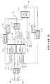
- the controller is configured to implement the models above using equations (6), (12) to determine the target temperature and humidity at the end of the hose. Once those targets have been determined, the controller is also configured to operate the humidification breathing apparatus to achieve those targets at the target point (end of hose). This was shown in overview in Figure 4 , and a detailed example of the overall apparatus control (implemented by the controller) for this embodiment is shown in Figure 10 .
- a user or physician inputs the preferred temperature and/or humidity settings into the humidification breathing apparatus via the user input control interface 114.
- Ambient temperature 19a is also received as an input into the controller, for example from a temperature sensor situated outside the breathing apparatus.
- the controller 109 contains a look up table or similar implementation that uses the ambient temperature 19a and user settings 19b to determine the desired mask humidity 42e and temperature 42d.
- the mask relative humidity (Mask_RH) and also mask temperature Mask_T) 42d and mask absolute humidity (Mask_AH)42e are pre-determined for each comfort setting for ambient temperatures from 5°C to 35°C and these are programmed into the controller look-up table. These values are defined based on feedback from patient trials or other empirical methods.
- the desired Mask_T 42d and Mask_AH 42e can be determined using two look-up tables in the unit memory for each user setting and different ambient temperatures.
- the controller 109 uses the desired mask humidity 42e and temperature 42 d as inputs into the equations (6), (12) that implement the target temperature and humidity models 50.
- the controller 109 also uses average flow 42a, peak flow 42b and ambient temperature 19aas inputs into those equations as received from the appropriate sensors/inputs.
- the target temperature and target humidity models 50 then output the target end of hose humidity (EOH_AH) 44b and temperatures (EOH_T) 44a as described previously.
- the controller 109 then operates the humidification breathing apparatus to achieve and maintain the target humidity and temperature.
- the controller does this by controlling the heater plate (HP) 108 to control target humidity and the heater (HBT)101a in the breathing tube to control target temperature.
- the controller 109 uses the target humidity (end of hose temperature 44a) along with ambient temperature 19a, ambient humidity 19c (measured by sensor or determined through a model) and average flow 42a as inputs into a neural network model or equations 120 that outputs the target heater plate temperature 43a that will achieve the target end of hose humidity 44b.
- the controller 109 also optionally uses an end of hose humidity sensor 122 reading as a feedback input into the model 120.
- the controller 109 uses the target temperature along with ambient temperature 19a, and average flow 42a and heater plate temperature 43a as inputs into a neural network model or equations 121 that outputs the target power 43b for the heated breathing tube 101 to achieve the target end of hose temperature 44a. It also optionally or as an alternative uses an end of hose temperature sensor 123 reading as a feedback input into the model 121..
- the controller 109 Based on the heater plate target temperature 43a and HBT target power 43b, the controller 109 generates and passes control voltages to the heater plate 108 and breathing tube heater 101a respectively to control them to attain and maintain the target heater plate temperature 43a and breathing tube power 43b to achieve the target temperature/humidity at the end of hose 44a, 44b.
- the above embodiment could be run as an open loop system, where no sensors are present to measure the output humidity and temperature. However, optionally, there can be sensors present to measure humidity and/or temperature in the mask or end of hose. If they are present, the following occurs: If a sensor 117 is implemented to measure temperature in the mask 102, the HBT power 43b will be adjusted according to the feedback control loop to maintain target mask temperature 42d. In this case, the target temperature model (T) 50 and neural network model (HBT) 121 would be bypassed. In this case, just the target humidity model 50 and neural network model 120 for the heater plate 108 would be used.
- the HP temperature/power 43a would be adjusted according to the feedback control loop to maintain target mask humidity 42e.
- the target humidity model (AH) 50 and neural network model (HP) 120 would be bypassed.
- just the target temperature model 50 and neural network model 121 for the breathing tube heater would be used.
- the HBT power 43b would be adjusted according to the feedback control loop to maintain target EOH T 44a.
- the neural network model (HBT) 121 would be bypassed.
- the patient contribution model (T) 50 would still be used to calculate EOH T 44a from Mask Temperature targets 42a.
- the HP temperature/power 43a will be adjusted according to the feedback control loop to maintain target EOH humidity 44b. In this case, the neural network model (HP) 120 would be bypassed.
- the humidity control model 120 as shown in can be a machine learning algorithm such as a neural network model or set of equations.
- a neural network model can be implemented in the controller to predict HP 43a and HBT settings 43b under different conditions, to achieve EOH targets (AH and T) 44b, 44a.
- the model 120 is trained using known inputs and outputs parameters from experimental data to mimic the relationships of the physical system. It is then implemented in the controller to predict the required settings output using a different set of inputs.
- the HP model 120 runs first. This model determines the HP temperature 43a to maintain target EOH AH 44b under different conditions (ambient T, ambient AH and flow).
- the HBT model 121 takes HP setting 43a as input and controls HBT power 43b to compensate for the remaining EOH_T 44a requirement under different conditions (ambient T and flow).
- the model can optionally comprise additional functionality to take into account another effect.
- the moisture pick-up capability and therefore the level of humidity being delivered decreases as well.
- a constant level of humidity can be maintained throughout the night.
- Step 1- Calculate the water level estimate
- a water level estimate will be calculated using the inputs: ambient absolute humidity (Amb_AH), target end of hose output humidity (EOH_AH), average flow (L/min) and CPAP run time for the night, as follows.
- Step 2 Calculating HP setting
- the model is divided into 2 subsystems: humidity model (mainly humidifier chamber) 120 and temperature model 121 (mainly heated breathing tube).
- the models described below relate to a particular humidification breathing apparatus configuration. If the configuration changes, the equations will change.
- the breathing apparatus configuration has a chamber to hold about 400ml of water, which is on top of a heater-plate, to evaporate the water in the chamber.
- This humidity is carried through the hose 101, which is heated across its surface using the HBT (heater in the breathing tube) 101a in order to prevent rainout due to drop in temperature.
- the power in the tube (P HBT ) is controlled to get the desired temperature 44a at the end of the hose as previously described.
- the target temperature and humidity models 50 could be envisaged, along with different heater plate120 and heated breathing tube 121 control models and implementations.
- the embodiment above uses the end of hose as the target point and the model used relates to the patient contribution that influences the humidity and temperature of the mask contributions.
- Other target points in the flow path of the breathing apparatus could be used, with the appropriate models used to compensate for contributions to humidity and temperature made by the downstream portions of the breathing apparatus.
- the humidifier outlet could be used as the target point and the model would take into account patient and breathing tube contributions.
- AH 42e and temperature42d in the mask cannot be independently controlled as both will be determined by the heater plate setting.
- An equation can be used to determine the HP setting for the particular ambient temperature, ambient humidity, average flow and desired mask_RH or EOH_RH.
- Embodiments described herein refer to the mask humidity and the mask temperature as the desired temperature/humidity proximate the patient, although this should not be considered limiting. Models could be created for achieving desired temperatures/humidities at other points in the flow path.
- parameters patient exhaled humidity and temperature and tidal volume
- parameters patient exhaled humidity and temperature and tidal volume
- tidal volume based on more information about patient (height, weight, lung volume, age, gender, BMI etc) or surroundings (ambient temperature, inhaled temperature etc), or if the patient is nose breathing or mouth breathing.
- BSA Body Surface Area
- W body Weight
- H body Height
- the RF in the above function can be replaced by br_period.
- the desired absolute humidity at the mask is referred to as Mask_AH, M h , h M , Mask Humidity, AH mixture , AH mask .
- the desired relative humidity at the mask is referred to as Mask_RH.
- the desired temperature at the mask is referred to as Mask_T, M t , T M , Mask Temperature, T mask .
- the absolute humidity of the air at the patient end of breathing tube is referred to as EOH_AH, h C , AH CPAP .
- the relative humidity of the air at the patient end of the breathing tube is referred to as EOH_RH.
- the temperature of the air at the patient end of the breathing tube is referred to as EOH_T, T C , T CPAP .
- the patient exhaled absolute humidity is referred to as Patient_AH, h P , Patient humidity, AH Patient .
- the patient exhaled temperature is referred to as Patient_T, T P , Patient temperature, T Patient .
- the generally constant flow rate leaving the bias holes of the mask (plus any leak through the mask) is referred to as Average Flow, Avg Flow, J B , av. Flow.
- the amplitude of the assumed sinusoidal patient flow rate is referred to as the Peak Flow, A.
- the ambient temperature is referred to as Amb_T, T A , Amb. Temperature, Ambient temperature, T amb .
- the ambient humidity is referred to as Amb_AH, Ambient humidity.
- the specific heat and (average) density of the air at constant (average) process pressure are referred to as C P and ⁇ respectively.
- the effective heat conduction coefficient through the mask is referred to as k eff.
- the surface area of the mask is referred to as S.
- the heater plate is referred to as HP.
- the heater in the breathing tube is referred to as HBT.
- the temperature of the heater-plate is referred to as T HPL .
- the power in the heated tube is referred to as P HBT .
- the neural network is referred to as NN.
- the tidal volume per breath is referred to as V LUNG .
- the time period of the breath is referred to as br_period.
- the respiration frequency is referred to as RF.
- Volumetric flow rate of the CPAP is referred to as V CPAP ,J C.
- Volumetric flow rate of the patient breath is referred to as V Patient ,J P .
- Volumetric flow rate going out through the bias holes is referred to as V bias ,J B , V total .
- Volume of the mask is referred to as V mask .
- Absolute humidity of the air in the mask is referred to as AH mask .
- the heat loss to ambient through the mask is referred to as Q lost .
- the forced convection resistance inside the mask is referred to as R in .
- the conduction resistance through the mask is referred to as R cond .
- the natural convection resistance from mask to ambient is referred to as R out .
- the temperature of the inner surface of the mask is referred to as T inWall .
- the temperature of the outer surface of the mask is referred to as T outWall .
Landscapes
- Health & Medical Sciences (AREA)
- Life Sciences & Earth Sciences (AREA)
- Hematology (AREA)
- Engineering & Computer Science (AREA)
- Anesthesiology (AREA)
- Animal Behavior & Ethology (AREA)
- Heart & Thoracic Surgery (AREA)
- Pulmonology (AREA)
- Emergency Medicine (AREA)
- Biomedical Technology (AREA)
- General Health & Medical Sciences (AREA)
- Public Health (AREA)
- Veterinary Medicine (AREA)
- Respiratory Apparatuses And Protective Means (AREA)
- Accommodation For Nursing Or Treatment Tables (AREA)
- Air Humidification (AREA)
- Thermotherapy And Cooling Therapy Devices (AREA)
Claims (14)
- Un appareil respiratoire à humidification (1) pour générer et distribuer de l'air humidifié (13) à un patient (12) à une température souhaitée à proximité du patient, comprenant :un trajet d'écoulement d'air (30), etun contrôleur (109) pour contrôler le fonctionnement de l'appareil respiratoire à humidification (1),le contrôleur (109) étant configuré pour faire fonctionner l'appareil respiratoire à humidification (1) pour contrôler la température à un point cible (14) dans le trajet d'écoulement (30) à une température cible (44a) pour obtenir la température distribuée souhaitée à un point de distribution patient dans le trajet d'écoulement en aval du point cible et à proximité du patient, la température cible (44a) étant déterminée sur la base de la température exhalée par le patient et l'écoulement (42a, 42b) en utilisant un modèle.
- Un appareil respiratoire à humidification (1) selon la revendication 1 comprenant en sus un conduit (101) couplé à une interface patient (102) qui font partie du trajet d'écoulement (30).
- Un appareil respiratoire à humidification (1) selon la revendication 2 dans lequel le point cible (14) dans le trajet d'écoulement (30) où le contrôleur (109) est configuré pour contrôler la température est au niveau (31) ou proche de l'extrémité à l'interface patient du conduit (101).
- Un appareil respiratoire à humidification (1) selon la revendication 2 ou 3 dans lequel l'interface patient (102) est un masque (102) et l'humidificateur (115) contrôle la température au point cible (14) dans le trajet d'écoulement (30) pour obtenir une température cible (44a) calculée à partir de la température (19d) et de l'écoulement (42a, 42b) exhalés par le patient (93), le rapport entre la température cible (44a), la température (19d) et l'écoulement (42a, 42b) exhalés par le patient (93) étant basé sur le bilan du flux thermique entrant et sortant du masque (102).
- Un appareil respiratoire à humidification (1) selon la revendication 4 dans lequel le bilan du flux thermique est
 (loss= perteaverage "beat" out = "chaleur" moyenne sortante "beat" in = "chaleur" entrante)
OùLa chaleur sortante comprend :•

 •
•
 La chaleur entrante comprend :•

 •
•


- Un appareil respiratoire à humidification (1) selon la revendication 4 or 5 dans lequel le rapport est défini par :
 TP est la température fournie par l'exhalation du patient dans le masqueA est le débit de pointe du patientJB est le débit d'air sortant par les trous de polarisationTA est la température ambiante mesurée par capteurMt est la température souhaitée du masqueEOH_T est la température de l'extrémité du flexible.
 - Un appareil respiratoire à humidification (1) selon une quelconque des revendications 4 à 6 dans lequel le rapport est défini par :
 Masque_T est la température souhaitée du masqueAmb_T est la température ambiante
 keff est le coefficient de conduction thermique efficace à travers le masque,S est la surface du masque,Cp est la chaleur spécifique de l'air à la pression constante du processus,ρ est la densité de l'air à la pression constante du processus,A est le débit de pointe du patient,JB est le débit d'air s'écoulant à travers le trous de polarisation,Patient_T est la température de l'air exhalé par le patient.
 - Un appareil respiratoire à humidification (1) selon la revendication 2 dans lequel le point (14) dans le trajet d'écoulement (30) où le contrôleur (109) est configuré pour contrôler la température est au niveau ou proche de la sortie de l'humidificateur.
- Un appareil respiratoire à humidification (1) selon une quelconque des revendications 1 à 8 comprenant un capteur de débit (110, 111, 112, 117) pour capter le débit.
- Un appareil respiratoire à humidification (1) selon une quelconque des revendications 1 à 9 dans lequel l'écoulement comprend une ou plusieurs des caractéristiques d'écoulement, c'est-à-dire un ou plusieurs éléments parmi :le débit moyen (42a),le débit de pointe (42b),le volume courant.
- Un appareil respiratoire à humidification (1) selon une quelconque des revendications 1 à 10 dans lequel la température exhalée par le patient est un ou plusieurs éléments parmi :une valeur prédéterminée,une valeur captée par un capteur,une valeur calculée à partir d'un ou plusieurs éléments parmi : l'IMC, la taille, le poids, le volume corporel ou toute autre caractéristique physiologique appropriée du patient.
- Un appareil respiratoire à humidification (1) selon une quelconque des revendications 1 à 11 dans lequel le contrôleur (109) est configuré pour faire fonctionner l'humidificateur (115) pour contrôler la température en contrôlant la mise sous tension d'un chauffage dans le conduit (101a) ou éventuellement la mise sous tension d'un appareil à plaque chauffante (108), pour chauffer l'air humidifié distribué (13).
- Un appareil respiratoire à humidification (1) selon une quelconque des revendications 1 à 12 dans lequel le contrôleur (109) est configuré en sus pour faire fonctionner l'humidificateur (115) pour contrôler la température d'entrée de l'air basée sur la température, et éventuellement dans lequel la température d'entrée de l'air est la température de l'air ambiant (19a) ou une valeur prédéterminée.
- Un appareil respiratoire à humidification (1) selon une quelconque des revendications 1 à 13 dans lequel le contrôleur est configuré en sus pour faire fonctionner l'appareil respiratoire à humidification (1) pour contrôler la température sur la base d'informations sur le masque, éventuellement dans lequel les informations sur le masque sont un ou plusieurs éléments parmi :le volume interne du masque,la surface du masque,le matériau du masque.
Priority Applications (1)
| Application Number | Priority Date | Filing Date | Title |
|---|---|---|---|
| EP20185023.7A EP3782687A1 (fr) | 2012-09-28 | 2013-09-30 | Contrôle d'un appareil de respiration et d'humification |
Applications Claiming Priority (2)
| Application Number | Priority Date | Filing Date | Title |
|---|---|---|---|
| US201261707629P | 2012-09-28 | 2012-09-28 | |
| PCT/US2013/062762 WO2014052983A1 (fr) | 2012-09-28 | 2013-09-30 | Contrôle d'un appareil de respiration et d'humification |
Related Child Applications (2)
| Application Number | Title | Priority Date | Filing Date |
|---|---|---|---|
| EP20185023.7A Division EP3782687A1 (fr) | 2012-09-28 | 2013-09-30 | Contrôle d'un appareil de respiration et d'humification |
| EP20185023.7A Division-Into EP3782687A1 (fr) | 2012-09-28 | 2013-09-30 | Contrôle d'un appareil de respiration et d'humification |
Publications (3)
| Publication Number | Publication Date |
|---|---|
| EP2897677A1 EP2897677A1 (fr) | 2015-07-29 |
| EP2897677A4 EP2897677A4 (fr) | 2016-05-25 |
| EP2897677B1 true EP2897677B1 (fr) | 2020-11-04 |
Family
ID=50389061
Family Applications (2)
| Application Number | Title | Priority Date | Filing Date |
|---|---|---|---|
| EP20185023.7A Pending EP3782687A1 (fr) | 2012-09-28 | 2013-09-30 | Contrôle d'un appareil de respiration et d'humification |
| EP13841022.0A Active EP2897677B1 (fr) | 2012-09-28 | 2013-09-30 | Contrôle d'un appareil de respiration et d'humification |
Family Applications Before (1)
| Application Number | Title | Priority Date | Filing Date |
|---|---|---|---|
| EP20185023.7A Pending EP3782687A1 (fr) | 2012-09-28 | 2013-09-30 | Contrôle d'un appareil de respiration et d'humification |
Country Status (6)
| Country | Link |
|---|---|
| US (2) | US10441740B2 (fr) |
| EP (2) | EP3782687A1 (fr) |
| JP (4) | JP6543192B2 (fr) |
| AU (5) | AU2013323113B2 (fr) |
| CA (1) | CA2886596A1 (fr) |
| WO (1) | WO2014052983A1 (fr) |
Families Citing this family (22)
| Publication number | Priority date | Publication date | Assignee | Title |
|---|---|---|---|---|
| DE102008022663B4 (de) | 2008-05-07 | 2012-10-31 | Schauenburg Hose Technology Gmbh | Stretch-Schlauch |
| US9505164B2 (en) | 2009-12-30 | 2016-11-29 | Schauenburg Technology Se | Tapered helically reinforced hose and its manufacture |
| US9964238B2 (en) | 2009-01-15 | 2018-05-08 | Globalmed, Inc. | Stretch hose and hose production method |
| US9320642B1 (en) * | 2012-06-04 | 2016-04-26 | The Surgical Company International B.V. | Method of and system for selecting patient temperature regulation tools |
| EP3220817B1 (fr) * | 2014-11-19 | 2022-03-30 | Koninklijke Philips N.V. | Procédé et dispositif permettant de déterminer l'état de santé d'un sujet |
| WO2016094423A1 (fr) | 2014-12-09 | 2016-06-16 | Flexicare, Inc. | Systèmes et procédés pour chauffer et humidifier des gaz inspirés au cours d'une ventilation mécanique |
| DE102015000845A1 (de) * | 2015-01-27 | 2016-07-28 | W.O.M. World Of Medicine Gmbh | Verfahren und Vorrichtung zur Regelung der Temperatur des Gasstroms bei medizintechnischen Vorrichtungen |
| WO2017126980A2 (fr) * | 2016-01-18 | 2017-07-27 | Fisher & Paykel Healthcare Limited | Humidification de gaz respiratoires |
| SG10202100532PA (en) | 2016-07-19 | 2021-02-25 | Fisher and paykel healthcare ltd | Water out alarm determination |
| WO2018056356A1 (fr) * | 2016-09-26 | 2018-03-29 | 株式会社メトラン | Dispositif d'assistance respiratoire et procédé d'assistance respiratoire |
| GB2601711B (en) | 2016-10-11 | 2022-11-30 | Fisher & Paykel Healthcare Ltd | Method of detecting errors in the connections in a humidification system |
| WO2018109006A1 (fr) * | 2016-12-14 | 2018-06-21 | Koninklijke Philips N.V. | Oxygénothérapie à haut débit avec humidification à la demande et valve expiratoire active |
| CA3053834C (fr) | 2017-01-30 | 2020-09-01 | Globalmed, Inc. | Ensemble de flexibles respiratoires chauffes |
| JP7177837B2 (ja) * | 2017-12-19 | 2022-11-24 | コーニンクレッカ フィリップス エヌ ヴェ | 低温通過加湿制御を行う換気システム |
| WO2019142381A1 (fr) * | 2018-01-17 | 2019-07-25 | オリンパス株式会社 | Dispositif d'alimentation en air |
| US11338105B2 (en) | 2018-03-27 | 2022-05-24 | Globalmed, Inc. | Respiratory humidification device |
| DE102018214556A1 (de) * | 2018-08-28 | 2020-03-05 | Hamilton Medical Ag | Beatmungsvorrichtung mit verbesserter Befeuchtung des Atemgases |
| CN111150917B (zh) * | 2019-12-31 | 2021-09-14 | 北京怡和嘉业医疗科技股份有限公司 | 一种通气治疗设备湿化控制系统和方法 |
| EP4200004A1 (fr) * | 2020-08-24 | 2023-06-28 | Fisher & Paykel Healthcare Limited | Protection contre la surenthalpie dans des systèmes d'humidificateur |
| CN113397800B (zh) * | 2021-05-20 | 2022-09-20 | 北京小汤山医院(北京小汤山疗养院、北京市小汤山康复医院、北京国际药膳博物馆北京市健康管理促进中心) | 一种穿脱式电蜡疗仪 |
| US11672933B1 (en) * | 2021-12-21 | 2023-06-13 | Nanotronics Health, LLC. | Method and system for bi-level treatment of sleep apnea |
| CN116474233B (zh) * | 2023-06-25 | 2023-08-22 | 斯莱达医疗用品(惠州)有限公司 | 一种医用湿化器输出量高精度控制方法、系统及介质 |
Family Cites Families (21)
| Publication number | Priority date | Publication date | Assignee | Title |
|---|---|---|---|---|
| US3326214A (en) * | 1963-10-10 | 1967-06-20 | Perma Pier Inc | Breath warmer apparatus |
| US5692497A (en) * | 1996-05-16 | 1997-12-02 | Children's Medical Center Corporation | Microprocessor-controlled ventilator system and methods |
| US20040221844A1 (en) * | 1997-06-17 | 2004-11-11 | Hunt Peter John | Humidity controller |
| US10130787B2 (en) * | 1997-06-17 | 2018-11-20 | Fisher & Paykel Healthcare Limited | Humidity controller |
| SE9804148D0 (sv) | 1998-12-01 | 1998-12-01 | Siemens Elema Ab | System and method for determining changes in body resources during aided breathing |
| SE0002051D0 (sv) * | 2000-05-31 | 2000-05-31 | Jan Hedner | Läckdetektor |
| DE10139881B4 (de) * | 2001-08-20 | 2017-06-08 | Resmed R&D Germany Gmbh | Vorrichtung zur Zufuhr eines Atemgases und Verfahren zur Steuerung derselben |
| HUE060036T2 (hu) | 2004-08-20 | 2023-01-28 | Fisher & Paykel Healthcare Ltd | Berendezés páciensnek szállított gázok tulajdonságainak mérésére |
| CN101252966B (zh) | 2005-05-26 | 2012-07-18 | 菲舍尔和佩克尔保健有限公司 | 呼吸辅助设备 |
| NZ596379A (en) | 2006-08-30 | 2013-02-22 | Resmed Ltd | Determining patency of airways from complex admittance by applying oscillating air flow for apnoea / apnea patients |
| US8851073B2 (en) * | 2006-09-29 | 2014-10-07 | Covidien Lp | Patient interface having an integrated system for communicating data to a ventilator |
| DE102007015038B3 (de) | 2007-02-08 | 2008-03-27 | Dräger Medical AG & Co. KG | Vorrichtung und Verfahren zum Bereitstellen von angefeuchtetem Atemgas |
| US8122882B2 (en) * | 2007-10-29 | 2012-02-28 | Smiths Medical Asd, Inc. | Rainout reduction in a breathing circuit |
| US9802022B2 (en) * | 2008-03-06 | 2017-10-31 | Resmed Limited | Humidification of respiratory gases |
| EP3756719B1 (fr) * | 2008-05-27 | 2024-01-24 | Fisher & Paykel Healthcare Limited | Système d'assistance respiratoire pour l'administration de gaz |
| TW201039872A (en) * | 2009-05-01 | 2010-11-16 | Top Vision Medical Equipment Consultant Co Ltd | Gas delivery mask with features of detection and adjustment of temperature and humidity |
| EP2432539A4 (fr) * | 2009-05-19 | 2012-11-28 | Beaumont Hospital William | Radiothérapie assistée par hyperthermie |
| JP2011125618A (ja) * | 2009-12-21 | 2011-06-30 | Pacific Medico Co Ltd | 人工呼吸器用加温加湿装置 |
| US20120017904A1 (en) * | 2010-07-26 | 2012-01-26 | Ratto David R | Breathing treatment system and method |
| JP2012165848A (ja) * | 2011-02-14 | 2012-09-06 | Pacific Medico Co Ltd | 人工呼吸器用加温加湿装置 |
| RU2014133564A (ru) * | 2012-02-24 | 2016-03-10 | Конинклейке Филипс Н.В. | Защита от выделения влаги при дыхательной терапии, содержащей увлажнение |
-
2013
- 2013-09-30 WO PCT/US2013/062762 patent/WO2014052983A1/fr active Application Filing
- 2013-09-30 JP JP2015534807A patent/JP6543192B2/ja active Active
- 2013-09-30 CA CA2886596A patent/CA2886596A1/fr active Pending
- 2013-09-30 EP EP20185023.7A patent/EP3782687A1/fr active Pending
- 2013-09-30 EP EP13841022.0A patent/EP2897677B1/fr active Active
- 2013-09-30 AU AU2013323113A patent/AU2013323113B2/en active Active
- 2013-09-30 US US14/432,159 patent/US10441740B2/en active Active
-
2018
- 2018-04-30 AU AU2018202966A patent/AU2018202966B2/en active Active
-
2019
- 2019-06-14 JP JP2019110781A patent/JP6853852B2/ja active Active
- 2019-09-04 US US16/560,247 patent/US20200009347A1/en active Pending
-
2020
- 2020-03-30 AU AU2020202230A patent/AU2020202230B2/en active Active
-
2021
- 2021-03-12 JP JP2021039871A patent/JP7431768B2/ja active Active
- 2021-12-08 AU AU2021282450A patent/AU2021282450B2/en active Active
-
2022
- 2022-09-20 JP JP2022148799A patent/JP7451637B2/ja active Active
-
2023
- 2023-12-18 AU AU2023285700A patent/AU2023285700A1/en active Pending
Non-Patent Citations (1)
| Title |
|---|
| None * |
Also Published As
| Publication number | Publication date |
|---|---|
| JP6543192B2 (ja) | 2019-07-10 |
| AU2020202230A1 (en) | 2020-04-16 |
| EP2897677A1 (fr) | 2015-07-29 |
| JP2022183160A (ja) | 2022-12-08 |
| EP2897677A4 (fr) | 2016-05-25 |
| JP2019171126A (ja) | 2019-10-10 |
| US20150217079A1 (en) | 2015-08-06 |
| JP2015533560A (ja) | 2015-11-26 |
| AU2021282450A1 (en) | 2022-01-06 |
| AU2018202966A1 (en) | 2018-05-17 |
| JP2021100592A (ja) | 2021-07-08 |
| AU2018202966B2 (en) | 2020-01-02 |
| CA2886596A1 (fr) | 2014-04-03 |
| US20200009347A1 (en) | 2020-01-09 |
| EP3782687A1 (fr) | 2021-02-24 |
| AU2020202230B2 (en) | 2021-09-09 |
| AU2021282450B2 (en) | 2023-10-19 |
| JP7431768B2 (ja) | 2024-02-15 |
| AU2013323113A1 (en) | 2015-04-16 |
| US10441740B2 (en) | 2019-10-15 |
| JP7451637B2 (ja) | 2024-03-18 |
| AU2013323113B2 (en) | 2018-05-17 |
| WO2014052983A1 (fr) | 2014-04-03 |
| AU2023285700A1 (en) | 2024-01-18 |
| JP6853852B2 (ja) | 2021-03-31 |
Similar Documents
| Publication | Publication Date | Title |
|---|---|---|
| AU2020202230B2 (en) | Humidification breathing apparatus control | |
| JP7278994B2 (ja) | 呼吸器加湿システム | |
| JP2020142099A (ja) | 湿度を正確に制御するための加湿器チャンバ温度の制御 | |
| AU2008360394B2 (en) | System and method for determining humidity in a respiratory treatment system | |
| US20140060533A1 (en) | Methods and system for humidifier control using enthalpy-based calculation |
Legal Events
| Date | Code | Title | Description |
|---|---|---|---|
| PUAI | Public reference made under article 153(3) epc to a published international application that has entered the european phase |
Free format text: ORIGINAL CODE: 0009012 |
|
| 17P | Request for examination filed |
Effective date: 20150423 |
|
| AK | Designated contracting states |
Kind code of ref document: A1 Designated state(s): AL AT BE BG CH CY CZ DE DK EE ES FI FR GB GR HR HU IE IS IT LI LT LU LV MC MK MT NL NO PL PT RO RS SE SI SK SM TR |
|
| AX | Request for extension of the european patent |
Extension state: BA ME |
|
| RIN1 | Information on inventor provided before grant (corrected) |
Inventor name: BUDHIRAJA, NIMANSHA Inventor name: YATSEVICH, IGOR, OLEGOVICH Inventor name: YOU, DONGXUE Inventor name: MCAULEY, ALASTAIR, EDWIN |
|
| RA4 | Supplementary search report drawn up and despatched (corrected) |
Effective date: 20160425 |
|
| RIC1 | Information provided on ipc code assigned before grant |
Ipc: A61M 16/16 20060101AFI20160419BHEP |
|
| STAA | Information on the status of an ep patent application or granted ep patent |
Free format text: STATUS: EXAMINATION IS IN PROGRESS |
|
| 17Q | First examination report despatched |
Effective date: 20180625 |
|
| GRAP | Despatch of communication of intention to grant a patent |
Free format text: ORIGINAL CODE: EPIDOSNIGR1 |
|
| STAA | Information on the status of an ep patent application or granted ep patent |
Free format text: STATUS: GRANT OF PATENT IS INTENDED |
|
| INTG | Intention to grant announced |
Effective date: 20200312 |
|
| GRAJ | Information related to disapproval of communication of intention to grant by the applicant or resumption of examination proceedings by the epo deleted |
Free format text: ORIGINAL CODE: EPIDOSDIGR1 |
|
| STAA | Information on the status of an ep patent application or granted ep patent |
Free format text: STATUS: EXAMINATION IS IN PROGRESS |
|
| INTC | Intention to grant announced (deleted) | ||
| GRAR | Information related to intention to grant a patent recorded |
Free format text: ORIGINAL CODE: EPIDOSNIGR71 |
|
| GRAS | Grant fee paid |
Free format text: ORIGINAL CODE: EPIDOSNIGR3 |
|
| STAA | Information on the status of an ep patent application or granted ep patent |
Free format text: STATUS: GRANT OF PATENT IS INTENDED |
|
| GRAA | (expected) grant |
Free format text: ORIGINAL CODE: 0009210 |
|
| STAA | Information on the status of an ep patent application or granted ep patent |
Free format text: STATUS: THE PATENT HAS BEEN GRANTED |
|
| INTG | Intention to grant announced |
Effective date: 20200914 |
|
| AK | Designated contracting states |
Kind code of ref document: B1 Designated state(s): AL AT BE BG CH CY CZ DE DK EE ES FI FR GB GR HR HU IE IS IT LI LT LU LV MC MK MT NL NO PL PT RO RS SE SI SK SM TR |
|
| AX | Request for extension of the european patent |
Extension state: BA ME |
|
| REG | Reference to a national code |
Ref country code: GB Ref legal event code: FG4D |
|
| REG | Reference to a national code |
Ref country code: CH Ref legal event code: EP |
|
| REG | Reference to a national code |
Ref country code: AT Ref legal event code: REF Ref document number: 1330007 Country of ref document: AT Kind code of ref document: T Effective date: 20201115 |
|
| REG | Reference to a national code |
Ref country code: IE Ref legal event code: FG4D |
|
| REG | Reference to a national code |
Ref country code: DE Ref legal event code: R096 Ref document number: 602013073857 Country of ref document: DE |
|
| REG | Reference to a national code |
Ref country code: NL Ref legal event code: MP Effective date: 20201104 |
|
| REG | Reference to a national code |
Ref country code: AT Ref legal event code: MK05 Ref document number: 1330007 Country of ref document: AT Kind code of ref document: T Effective date: 20201104 |
|
| PG25 | Lapsed in a contracting state [announced via postgrant information from national office to epo] |
Ref country code: NO Free format text: LAPSE BECAUSE OF FAILURE TO SUBMIT A TRANSLATION OF THE DESCRIPTION OR TO PAY THE FEE WITHIN THE PRESCRIBED TIME-LIMIT Effective date: 20210204 Ref country code: PT Free format text: LAPSE BECAUSE OF FAILURE TO SUBMIT A TRANSLATION OF THE DESCRIPTION OR TO PAY THE FEE WITHIN THE PRESCRIBED TIME-LIMIT Effective date: 20210304 Ref country code: FI Free format text: LAPSE BECAUSE OF FAILURE TO SUBMIT A TRANSLATION OF THE DESCRIPTION OR TO PAY THE FEE WITHIN THE PRESCRIBED TIME-LIMIT Effective date: 20201104 Ref country code: RS Free format text: LAPSE BECAUSE OF FAILURE TO SUBMIT A TRANSLATION OF THE DESCRIPTION OR TO PAY THE FEE WITHIN THE PRESCRIBED TIME-LIMIT Effective date: 20201104 Ref country code: GR Free format text: LAPSE BECAUSE OF FAILURE TO SUBMIT A TRANSLATION OF THE DESCRIPTION OR TO PAY THE FEE WITHIN THE PRESCRIBED TIME-LIMIT Effective date: 20210205 |
|
| PG25 | Lapsed in a contracting state [announced via postgrant information from national office to epo] |
Ref country code: LV Free format text: LAPSE BECAUSE OF FAILURE TO SUBMIT A TRANSLATION OF THE DESCRIPTION OR TO PAY THE FEE WITHIN THE PRESCRIBED TIME-LIMIT Effective date: 20201104 Ref country code: PL Free format text: LAPSE BECAUSE OF FAILURE TO SUBMIT A TRANSLATION OF THE DESCRIPTION OR TO PAY THE FEE WITHIN THE PRESCRIBED TIME-LIMIT Effective date: 20201104 Ref country code: SE Free format text: LAPSE BECAUSE OF FAILURE TO SUBMIT A TRANSLATION OF THE DESCRIPTION OR TO PAY THE FEE WITHIN THE PRESCRIBED TIME-LIMIT Effective date: 20201104 Ref country code: IS Free format text: LAPSE BECAUSE OF FAILURE TO SUBMIT A TRANSLATION OF THE DESCRIPTION OR TO PAY THE FEE WITHIN THE PRESCRIBED TIME-LIMIT Effective date: 20210304 Ref country code: BG Free format text: LAPSE BECAUSE OF FAILURE TO SUBMIT A TRANSLATION OF THE DESCRIPTION OR TO PAY THE FEE WITHIN THE PRESCRIBED TIME-LIMIT Effective date: 20210204 Ref country code: ES Free format text: LAPSE BECAUSE OF FAILURE TO SUBMIT A TRANSLATION OF THE DESCRIPTION OR TO PAY THE FEE WITHIN THE PRESCRIBED TIME-LIMIT Effective date: 20201104 Ref country code: AT Free format text: LAPSE BECAUSE OF FAILURE TO SUBMIT A TRANSLATION OF THE DESCRIPTION OR TO PAY THE FEE WITHIN THE PRESCRIBED TIME-LIMIT Effective date: 20201104 |
|
| REG | Reference to a national code |
Ref country code: LT Ref legal event code: MG9D |
|
| PG25 | Lapsed in a contracting state [announced via postgrant information from national office to epo] |
Ref country code: HR Free format text: LAPSE BECAUSE OF FAILURE TO SUBMIT A TRANSLATION OF THE DESCRIPTION OR TO PAY THE FEE WITHIN THE PRESCRIBED TIME-LIMIT Effective date: 20201104 |
|
| PG25 | Lapsed in a contracting state [announced via postgrant information from national office to epo] |
Ref country code: LT Free format text: LAPSE BECAUSE OF FAILURE TO SUBMIT A TRANSLATION OF THE DESCRIPTION OR TO PAY THE FEE WITHIN THE PRESCRIBED TIME-LIMIT Effective date: 20201104 Ref country code: RO Free format text: LAPSE BECAUSE OF FAILURE TO SUBMIT A TRANSLATION OF THE DESCRIPTION OR TO PAY THE FEE WITHIN THE PRESCRIBED TIME-LIMIT Effective date: 20201104 Ref country code: SK Free format text: LAPSE BECAUSE OF FAILURE TO SUBMIT A TRANSLATION OF THE DESCRIPTION OR TO PAY THE FEE WITHIN THE PRESCRIBED TIME-LIMIT Effective date: 20201104 Ref country code: SM Free format text: LAPSE BECAUSE OF FAILURE TO SUBMIT A TRANSLATION OF THE DESCRIPTION OR TO PAY THE FEE WITHIN THE PRESCRIBED TIME-LIMIT Effective date: 20201104 Ref country code: EE Free format text: LAPSE BECAUSE OF FAILURE TO SUBMIT A TRANSLATION OF THE DESCRIPTION OR TO PAY THE FEE WITHIN THE PRESCRIBED TIME-LIMIT Effective date: 20201104 Ref country code: CZ Free format text: LAPSE BECAUSE OF FAILURE TO SUBMIT A TRANSLATION OF THE DESCRIPTION OR TO PAY THE FEE WITHIN THE PRESCRIBED TIME-LIMIT Effective date: 20201104 |
|
| REG | Reference to a national code |
Ref country code: DE Ref legal event code: R097 Ref document number: 602013073857 Country of ref document: DE |
|
| PG25 | Lapsed in a contracting state [announced via postgrant information from national office to epo] |
Ref country code: DK Free format text: LAPSE BECAUSE OF FAILURE TO SUBMIT A TRANSLATION OF THE DESCRIPTION OR TO PAY THE FEE WITHIN THE PRESCRIBED TIME-LIMIT Effective date: 20201104 |
|
| PLBE | No opposition filed within time limit |
Free format text: ORIGINAL CODE: 0009261 |
|
| STAA | Information on the status of an ep patent application or granted ep patent |
Free format text: STATUS: NO OPPOSITION FILED WITHIN TIME LIMIT |
|
| 26N | No opposition filed |
Effective date: 20210805 |
|
| PG25 | Lapsed in a contracting state [announced via postgrant information from national office to epo] |
Ref country code: IT Free format text: LAPSE BECAUSE OF FAILURE TO SUBMIT A TRANSLATION OF THE DESCRIPTION OR TO PAY THE FEE WITHIN THE PRESCRIBED TIME-LIMIT Effective date: 20201104 Ref country code: NL Free format text: LAPSE BECAUSE OF FAILURE TO SUBMIT A TRANSLATION OF THE DESCRIPTION OR TO PAY THE FEE WITHIN THE PRESCRIBED TIME-LIMIT Effective date: 20201104 Ref country code: AL Free format text: LAPSE BECAUSE OF FAILURE TO SUBMIT A TRANSLATION OF THE DESCRIPTION OR TO PAY THE FEE WITHIN THE PRESCRIBED TIME-LIMIT Effective date: 20201104 |
|
| PG25 | Lapsed in a contracting state [announced via postgrant information from national office to epo] |
Ref country code: SI Free format text: LAPSE BECAUSE OF FAILURE TO SUBMIT A TRANSLATION OF THE DESCRIPTION OR TO PAY THE FEE WITHIN THE PRESCRIBED TIME-LIMIT Effective date: 20201104 |
|
| REG | Reference to a national code |
Ref country code: CH Ref legal event code: PL |
|
| REG | Reference to a national code |
Ref country code: BE Ref legal event code: MM Effective date: 20210930 |
|
| PG25 | Lapsed in a contracting state [announced via postgrant information from national office to epo] |
Ref country code: IS Free format text: LAPSE BECAUSE OF FAILURE TO SUBMIT A TRANSLATION OF THE DESCRIPTION OR TO PAY THE FEE WITHIN THE PRESCRIBED TIME-LIMIT Effective date: 20210304 Ref country code: MC Free format text: LAPSE BECAUSE OF FAILURE TO SUBMIT A TRANSLATION OF THE DESCRIPTION OR TO PAY THE FEE WITHIN THE PRESCRIBED TIME-LIMIT Effective date: 20201104 |
|
| PG25 | Lapsed in a contracting state [announced via postgrant information from national office to epo] |
Ref country code: LU Free format text: LAPSE BECAUSE OF NON-PAYMENT OF DUE FEES Effective date: 20210930 Ref country code: IE Free format text: LAPSE BECAUSE OF NON-PAYMENT OF DUE FEES Effective date: 20210930 Ref country code: BE Free format text: LAPSE BECAUSE OF NON-PAYMENT OF DUE FEES Effective date: 20210930 |
|
| PG25 | Lapsed in a contracting state [announced via postgrant information from national office to epo] |
Ref country code: LI Free format text: LAPSE BECAUSE OF NON-PAYMENT OF DUE FEES Effective date: 20210930 Ref country code: CH Free format text: LAPSE BECAUSE OF NON-PAYMENT OF DUE FEES Effective date: 20210930 |
|
| PG25 | Lapsed in a contracting state [announced via postgrant information from national office to epo] |
Ref country code: HU Free format text: LAPSE BECAUSE OF FAILURE TO SUBMIT A TRANSLATION OF THE DESCRIPTION OR TO PAY THE FEE WITHIN THE PRESCRIBED TIME-LIMIT; INVALID AB INITIO Effective date: 20130930 |
|
| PG25 | Lapsed in a contracting state [announced via postgrant information from national office to epo] |
Ref country code: CY Free format text: LAPSE BECAUSE OF FAILURE TO SUBMIT A TRANSLATION OF THE DESCRIPTION OR TO PAY THE FEE WITHIN THE PRESCRIBED TIME-LIMIT Effective date: 20201104 |
|
| P01 | Opt-out of the competence of the unified patent court (upc) registered |
Effective date: 20230526 |
|
| PGFP | Annual fee paid to national office [announced via postgrant information from national office to epo] |
Ref country code: GB Payment date: 20230823 Year of fee payment: 11 |
|
| PGFP | Annual fee paid to national office [announced via postgrant information from national office to epo] |
Ref country code: FR Payment date: 20230822 Year of fee payment: 11 Ref country code: DE Payment date: 20230822 Year of fee payment: 11 |