EP2897512B1 - Manufacturing method; double-walled, vacuum-insulated container - Google Patents
Manufacturing method; double-walled, vacuum-insulated container Download PDFInfo
- Publication number
- EP2897512B1 EP2897512B1 EP14753190.9A EP14753190A EP2897512B1 EP 2897512 B1 EP2897512 B1 EP 2897512B1 EP 14753190 A EP14753190 A EP 14753190A EP 2897512 B1 EP2897512 B1 EP 2897512B1
- Authority
- EP
- European Patent Office
- Prior art keywords
- container
- vacuum
- coating
- outer body
- plenum
- Prior art date
- Legal status (The legal status is an assumption and is not a legal conclusion. Google has not performed a legal analysis and makes no representation as to the accuracy of the status listed.)
- Not-in-force
Links
Images



Classifications
-
- B—PERFORMING OPERATIONS; TRANSPORTING
- B65—CONVEYING; PACKING; STORING; HANDLING THIN OR FILAMENTARY MATERIAL
- B65D—CONTAINERS FOR STORAGE OR TRANSPORT OF ARTICLES OR MATERIALS, e.g. BAGS, BARRELS, BOTTLES, BOXES, CANS, CARTONS, CRATES, DRUMS, JARS, TANKS, HOPPERS, FORWARDING CONTAINERS; ACCESSORIES, CLOSURES, OR FITTINGS THEREFOR; PACKAGING ELEMENTS; PACKAGES
- B65D81/00—Containers, packaging elements, or packages, for contents presenting particular transport or storage problems, or adapted to be used for non-packaging purposes after removal of contents
- B65D81/38—Containers, packaging elements, or packages, for contents presenting particular transport or storage problems, or adapted to be used for non-packaging purposes after removal of contents with thermal insulation
- B65D81/3837—Containers, packaging elements, or packages, for contents presenting particular transport or storage problems, or adapted to be used for non-packaging purposes after removal of contents with thermal insulation rigid container in the form of a bottle, jar or like container
- B65D81/3841—Containers, packaging elements, or packages, for contents presenting particular transport or storage problems, or adapted to be used for non-packaging purposes after removal of contents with thermal insulation rigid container in the form of a bottle, jar or like container formed with double walls, i.e. hollow
-
- A—HUMAN NECESSITIES
- A47—FURNITURE; DOMESTIC ARTICLES OR APPLIANCES; COFFEE MILLS; SPICE MILLS; SUCTION CLEANERS IN GENERAL
- A47J—KITCHEN EQUIPMENT; COFFEE MILLS; SPICE MILLS; APPARATUS FOR MAKING BEVERAGES
- A47J41/00—Thermally-insulated vessels, e.g. flasks, jugs, jars
- A47J41/02—Vacuum-jacket vessels, e.g. vacuum bottles
- A47J41/022—Constructional details of the elements forming vacuum space
- A47J41/028—Constructional details of the elements forming vacuum space made of metal
-
- B—PERFORMING OPERATIONS; TRANSPORTING
- B23—MACHINE TOOLS; METAL-WORKING NOT OTHERWISE PROVIDED FOR
- B23K—SOLDERING OR UNSOLDERING; WELDING; CLADDING OR PLATING BY SOLDERING OR WELDING; CUTTING BY APPLYING HEAT LOCALLY, e.g. FLAME CUTTING; WORKING BY LASER BEAM
- B23K31/00—Processes relevant to this subclass, specially adapted for particular articles or purposes, but not covered by any single one of main groups B23K1/00 - B23K28/00
- B23K31/02—Processes relevant to this subclass, specially adapted for particular articles or purposes, but not covered by any single one of main groups B23K1/00 - B23K28/00 relating to soldering or welding
-
- Y—GENERAL TAGGING OF NEW TECHNOLOGICAL DEVELOPMENTS; GENERAL TAGGING OF CROSS-SECTIONAL TECHNOLOGIES SPANNING OVER SEVERAL SECTIONS OF THE IPC; TECHNICAL SUBJECTS COVERED BY FORMER USPC CROSS-REFERENCE ART COLLECTIONS [XRACs] AND DIGESTS
- Y10—TECHNICAL SUBJECTS COVERED BY FORMER USPC
- Y10T—TECHNICAL SUBJECTS COVERED BY FORMER US CLASSIFICATION
- Y10T29/00—Metal working
- Y10T29/49—Method of mechanical manufacture
- Y10T29/49826—Assembling or joining
- Y10T29/49888—Subsequently coating
Definitions
- ceramic mugs can hold hot beverages, but the mugs do not keep the beverage hot very long. Also, the mugs do not resist impact and are easily broken. As a consequence, ceramic mugs are not easily transportable.
- plastic containers can be used, but the drawbacks of plastic are well known.
- Stainless steel containers are also used to hold beverages, and double-walled, vacuum-insulated stainless steel containers can be used to hold hot and cold beverages or food. When holding hot beverages or food, the stainless steel may impart a metallic taste to the beverage or food and may change its flavor to an extent.
- Aluminum bottles can be used to hold beverages. However, the aluminum bottle does not retain heat for use with hot beverages. Also, the aluminum of the bottle can have an odor that negatively impacts the taste of the beverage, especially when hot. To combat the negative taste of the aluminum, aluminum water bottles are available that use an epoxy on the inside of a single-wall aluminum bottle. Unfortunately, the aluminum bottle with epoxy coating cannot keep cold beverages cold and cannot be used for hot beverages (coffee, tea, hot water, etc.) because they will burn the user's hand.
- a double-walled, vacuum-insulated container made of stainless steel can have problems when the inside of the container is treated only with electrolysis. It is also recognized that such a container made of metal can have problems when the inside of the container is treated only with an epoxy or resin.
- Japanese Patent JP3390349 notes that a fluoro-resin coated on the inside of such a metal container is porous, making the coating easily damaged and stained. Additionally, if the application temperature of the fluororesin (e.g., perfluoroalkoxy copolymer resin (PFA)) is higher than the melting temperature of sealing material that seals an exhaust port for the vacuum formation, then use of the fluororesin is a problem as it becomes impossible to hold the vacuum.
- Flouroresins can have cure temperatures of as high as 370°C for PTFE and PFA.
- Japanese Patent document JPH08338 discloses a double-walled, vacuum-insulated container having a film of a ceramic material mixed with antibacterial agent applied to the inside of the container.
- an inner body has the ceramic coating with the antimicrobial agent applied to the inner surface.
- the coating film is heated for about 20-min. at around 120°C.
- Aluminum foil is arranged outside the inner body, and an outer body 9 is jointed around the inner body at a seam.
- a tip pipe on the outer body is used to pull a vacuum in the space between the inner and outer bodies, and the tip pipe is sealed.
- a base is attached to the bottom of the outside body to cover the tip pipe.
- Japanese Patent document JP3390349 discloses coating inside the container with porcelain enamel, ceramic, or metal plating. For each of these coatings, manufacture of the container involves coating the inside of the container and then evacuating the space in the container to create the vacuum.
- JP2002080075 merely contemplates using a ceramic coating inside the vacuum space of a double-walled container.
- JP2000116541 discloses another method of coating the interior of a metallic vacuum double container. Insulating double-layered containers are also disclosed in EP0109262 and EP0880929 .
- a container of suitable material that can be used with hot and cold beverages, food, or the like and can avoid negatively impacting the taste or odor of the contents, while being durable.
- Conventional wisdom has solved this by applying a coating, such as a ceramic coating, inside a double-walled container and then pulling a vacuum on the container.
- the subject matter of the present disclosure is directed to overcoming, or at least reducing the effects of, one or more of the problems set forth above.
- a double-walled, vacuum-insulated container as claimed in claim 12.
- a double-walled, vacuum insulated container is manufactured having a cured inner coating.
- the container can be used for holding liquid, beverage, food, or other edible contents.
- the double-walled container is formed having a plenum enclosed between an inner body and an outer body.
- the inner body is disposed in the outer body, which can both be formed from stainless steel.
- the inner body has an inner sidewall, an inner bottom, and an inner lip
- the outer body has an outer sidewall and an outer lip.
- the inner and outer lips are affixed together.
- the plenum is then enclosed between the inner body and the outer body by affixing an outer bottom to the outer body.
- the manufacturing process creates a vacuum at least partially in the plenum using a seal having a first melt point.
- the inner coating is then painted/sprayed on an inside surface of the inner body, and the painted coating is cured with a temperature level being about 300 to 320°C and below the first melt point of the vacuum's seal.
- the paint coating has a drying temperature at about 300 to 320°C.
- the inner and outer lips can be welded together with an affixation having a second melt point. In this way, curing the painted coating can be performed at a temperature level below the first and second melt points.
- the vacuum can be drawn from the plenum, and a septum, an evacuation port, or the like on the container can be sealed with a first melt point between 450°C and 500°C to enclose the vacuum in the plenum.
- the temperature level for curing the painted coating is about 300°C to 320°C.
- the container with the painted inner coating and drawn vacuum can be passed through a heat tunnel.
- the temperature level of the heat tunnel is about 300°C to 320°C
- a double-walled, vacuum-insulated container 10 illustrated in Figures 1A-1 B includes an outer body 20, an inner body or liner 30, and a ceramic-type paint coating 40.
- the container 10 may also include other components, such as a molded mouth 50 and even a molded base (not shown) on which to support the container 10.
- the vacuum-insulated container 10 allows users to take hot or cold liquids, beverages, soup, food, or other edible contents on-the-go, and the paint coating 40 inside the container 10 makes the container 10 relatively tasteless, odorless, and easy to clean.
- the preferred paint coating 40 is painted and cured to be more robust than a mere epoxy or non-stick type of surface applied inside a container.
- FIG 1A illustrates an elevational view of the dual-walled, vacuum-insulated container 10 according to the present disclosure.
- the container 10 can be used for various types of hot and cold beverages.
- the main construction of the container 10 is preferably stainless steel, although other metal materials can be used.
- Certain components, such as a mouth 50 of the container 10 and any lid (not shown) may be composed of different materials, such as injected molded plastic or the like.
- the lid can thread onto the mouth 50 of the container 10, may sealably insert into the mouth 50, or may affix by other known methods.
- the container 10 may also include a molded support of plastic or rubber disposed on the container's bottom end.
- the double-walled, vacuum-insulated container 10 has the outer body 20 with the inner liner 30 disposed therein.
- the inner liner 30 is separated on all sides from the sidewall of the outer body 20, and primarily only the upper lip 32 of the liner 30 is affixed (e.g., welded, brazed, etc.) to the lip 22 of the outer body 20. Even the bases 24 and 34 of the outer body 20 and liner 30 are preferably separate from one another.
- the plenum 25 between the outer body 20 and the liner 30 can be a vacuum (or at least partial vacuum) to provide insulation between the contents to be held in the liner 30 from the environment outside the outer body 20.
- Molded components such as the mouth 50, may be affixed at the top of the container 10 where the lips 22, 32 affix together.
- the liner 30 has the paint coating 40 applied thereto so that the metal material (e.g., stainless steel) of the liner 30 does not contact the contained liquid, beverage, food, etc. directly.
- This coating 40 is a ceramic-type paint coating that simulates ceramic, as will be described in more detail below.
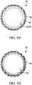
- Figures 1C-1D illustrate top and bottom views of the double-walled, vacuum-insulated container 10 having the inner coating 40.
- the top view of Figure 1C shows the molded components of the mouth 50 around the top of the container 10 and shows the inside surface of the liner 30 having the inner coating 40.
- the bottom view of Figure 1D shows the base 24 of the container's outer body 20.
- the container 10 can have different shapes and sizes to hold edible contents.
- Figure 2 shows another container 10 for holding food or the like. Many of the features of this container 10 are similar to those discussed previously so that the same reference numerals are used.
- the container 10 may include a molded base 12.
- Forming the disclosed container 10 requires combining two incompatible types of technologies.
- the container 10 is first formed with vacuum insulation between the two walls of the stainless steel liner 30 and outer body 20 and is then coated with a sprayed coating 40 on the inside of the liner 30. Both of these processes require temperatures for welding, drying, curing, etc. that can interfere with one another.
- a process 100 as shown in Figure 3 is used for forming the double-walled, vacuum-insulated container 10 having the inner coating 40.
- a normal drying temperature for a conventional paint coating is about 160°C.
- a drying temperature for the ceramic-type paint coating 40 used on the insulated container 10 of the present disclosure is about 300 to 320°C.
- the paint coating 40 applied inside the liner 30 of the double-walled, vacuum-insulated container 10 and cured at an elevated temperature of about 300-320°C produces a durable, abrasive-resistant, and uniform surface for use with hot and cold beverages and food.
- the process 100 of forming the container 10 preferably has two stages as shown in Figure 3 .
- the disclosed process 100 of forming the container 10 produces a cured inner coating 40 on the container 10 of preferred quality.
- the double-walled, vacuum-insulated container 10 is formed with the vacuum insulation.
- the components of the container 10 are formed using hydro-forming equipment to shape the container's components.
- welding is performed to weld the outer and inner walled components of the container 10 together.
- the melt point for the welds may be quite elevated and may even be about 3100°C.
- the vacuum is pulled on the plenum 25 between the walls of the container 10. Pulling the vacuum is done in a furnace at an elevated temperature of about 500°C. Getter materials can be used to absorb remaining gases.
- a cap, seal, or plug 12 can be formed or applied to an evacuation port 26 or the like on the outer body 20 to enclose the vacuum in the plenum 25.
- a brazing material can be disposed next to an evacuation port 26 on the outer body 20 and can seal the evacuation port 26 when the brazing material is melted and then hardened as the seal 12 after the vacuum has been drawn.
- the port 26 may include a tube, septum, or tail on the outer body 20, which can be closed or pinched off in a seal to enclose the vacuum in the plenum 25.
- the tube may be composed of copper welded to the evacuation port 26 on the container 10 so the vacuum can be pulled from the plenum 25. Once the vacuum is at least partially created, portion of the tube can be cut and then sealed to enclose the vacuum in the evacuated plenum 25. These and other vacuum sealing techniques can be used.
- the coating can be composed of suitable ceramic-type coating components-e.g., a polymer composite with insulating ceramics, a water-based nano- coating in ceramic, an aluminum oxide ceramic coating, a solvent-based silicone coating, or others.
- a suitable ceramic-type coating includes Water Ceramic Paint available from Shenzhen Hongshi Chemicals, Ltd of China.
- this coating is a water-based ceramic paint and includes three liquid components, which are combined together in a particular sequence and allowed to mature to produce the paint coating 40 for sparying on the liner 30.
- a fourth step 104 the paint coating 40 is sprayed on the inside of the container's liner 30.
- a 360° nozzle can be used to coat the inside of the container's liner 30 uniformly.
- the coating 40 is cured and dried at an elevated temperature of about 300°C to 320°C. This drying temperature and process cannot interfere with the welds used to form the container 10 or with the seal used to seal the vacuum of the container 10. Overall, the paint coating 40 may have a thickness of about 0.015 to 0.06 mm.
- final product decorations can be applied to the container 10 when at a particular temperature, such as 160°C. These final decorations may include application of exterior paint on the outside of the container 10, addition of molded plastic components to the container 10, etc.
- a process 110 is shown for assembling the disclosed container 10 from a liner 30, an inner base 32, an outer body 20, and a body base 24.
- the liner 30 and outer body 20 are cylindrical tubes or pieces that can be formed by hydroforming. Stamping two cylindrical halves and welding them together could be used as an alternative manufacturing step.
- hydro-forming is a die molding process that uses pressurized fluid to form the metal pieces. Due to the cylindrical nature of the container 10, tube hydroforming is used to expand raw metal tubes or pipes into a shape using two die halves.
- the raw tube component can be loaded into hydroforming dies, which is then closed. Sealing rods engage and seal the ends of the raw tube component. Fluid pressure is increased inside the tube component, and the sealing rods push the tube into the die as the internal pressure is ramped up. In the end, the tube component takes on the shape of the surrounding die.
- the inner base 34 and the body base 24 are generally flat components for affixing to open ends of the liner 30 and outer body 20 respectively, and they can be formed by stamping, hydroforming, or other process.
- the liner 30 is formed by drawing the raw, stainless steel pipe and cutting it to length. Ends of the cut pipe are deburred, and the lip 32 is formed on one end using hydroforming. Overall, the surface of the cut pipe is flattened and smoothed, and the prepared piece is washed and heated.
- the inner base 34 is formed by stamping or the like, and the base 34 is washed and heated.
- the heated inner base 34 and the liner piece 30 are then assembled with the inner base 34 disposed at the opposite open end to the liner's lip 32.
- the inner base 34 is then welded to the liner 30 to form a closed body with only the lip 32 being open.
- the liner 30 is then tested for leakage to ensure proper welding and the like (Block 118).
- the outer body 20 is formed in a fashion similar to the liner 30.
- the outer body 20 is formed by drawing the raw, stainless steel pipe and cutting it to length. Ends of the cut pipe are deburred.
- the outer body 20 may have additional shapes and counters so neck, mouth, lip, ribs, and other features are formed on the outer body 20 using hydroforming. Overall, the surface of the body 20 is flattened and smoothed, and the prepared body piece 20 is washed.
- the components are heated (Blocks 122 & 124), and the liner 30 is assembled inside the outer body piece 20 (Block 126).
- the seams at the lips 22 and 32 of the liner 30 and outer body piece 20 are then welded so that the liner 30 fits primarily suspended inside the outer body piece 20 (Block 128).
- the melt point for this weld at the lips 22 and 32 may be quite high and may even be about 3100°C.
- the body base 24 is formed by stamping or the like, and the base 24 is washed and heated.
- a getter material (14: Figs. 1B and 2 ) can then be used in assembling the container 10 and can be applied as appropriate to one or more components, such as base 24 (Block 132).
- the getter material 14 can react with residual gas in the container's plenum 25 when the vacuum is formed.
- the body base 24 is then assembled on the outer body piece 20 with the base 24 disposed at the opposite open end to the body's neck and lip 22 (Block 134).
- the base 24 is then welded to the body 20 to enclose the liner 30 inside the container 10 (Block 136).
- a vacuum process is used to form a vacuum at least partially inside the plenum 25 of the outer body 20 and liner 30 (Block 138). Understanding the weld melt points for the various welds used is helpful in later stages of manufacture so the future vacuum in the container 10 is not lost, for example, when curing the coating 40 inside the liner 30.
- a vacuum process 140 forms the vacuum in the plenum 25 of the container 10.
- a number of vacuum processes can be used. As noted previously, some of the processes for forming the vacuum may use a septum or evacuation port 26 and may then require a seal 12 to be made over the septum or port 26 to hold the vacuum in the container 10.
- the melt point temperature of the seal 12 over the septum or port 26 is preferably between 450°C and 500°C. As can be seen in this case, not only are the melt points of the welds need to be understood, but the melt point of the vacuum seal 12 needs to be known so the vacuum seal is not damage during subsequent coating and drying processes to apply the ceramic-type coating 40 described later.
- the assembly process of Figure 5 then continues with additional steps.
- the temperature of the container 10 is checked multiple times to ensure it is not overheated or damaged.
- abrasive blasting and electrolyzing are performed (Block 142).
- Another temperature check is made, and the seam of the container 10 is sanded (Block 144).
- the container 10 is then rammed, varnished, painted, and cured, as the case may be (Block 146).
- a final temperature check can be made, and then injection molded parts (e.g., mouth 50) can be assembled on the container 10 (Block 150).
- the container 10 can be packaged (Block 152).
- the coating 40 is preferably applied after the vacuum is pulled so that the coating 40 is not harmed during any vacuum forming process. All the same, the coating process cannot interfere with the assembly welds, vacuum seals, and the like used in forming the disclosed container 10.
- Figure 6 illustrates a process 160 for painting the inside of the liner 30 in the disclosed container 10 with the coating 40.
- Dust is removed from the liner 30 (Block 162), and the container 10 is pre-heated to a temperature between 40°C and 100°C for between 4 to 10 minutes (Block 164).
- the container 10 is loaded into the painter machine, and the paint head coats the inside surface of the liner 30 (Blocks 166-168).
- the spray printing gun can use multi-nozzles providing a 360° spray area to apply the coating 40 inside the liner 30.
- One particular spray printing gun is available from Taiwan Prona Industries Co., Ltd.
- Paint is followed by a flash-off period of 1 to 3 minutes, and the paint coating 40 is allowed to dry and harden (Blocks 170-172).
- the drying process uses temperatures at 300°C to 320°C for 30 to 35 minutes, and the spray printing line uses a high temperature drying tunnel at about 300°C to 320°C, which is about twice the normal drying temperature of a conventional paint coating.
- the paint coating 40 of the liner 30 can be inspected (Block 174).
- Figure 7 illustrates a process 180 for painting the outside of the body 20 on the disclosed container 10. Dust is removed from the outer body 20 (Block 182), and the container is pre-heated to a temperature between 50°C and 100°C for between 4 to 10 minutes (Block 184). The container 10 is loaded into the painter machine, and the outside surface of the body 20 is painted (Blocks 186-188). Painting is followed by a flash-off period of 3 to 5 minutes, and the paint is then allowed to dry and harden (Blocks 190-192). The drying process can use temperatures at 140°C to 150°C for 30 to 40 minutes. Finally, the painting on the outer body 20 can be inspected (Block 194).
Landscapes
- Engineering & Computer Science (AREA)
- Mechanical Engineering (AREA)
- Physics & Mathematics (AREA)
- Thermal Sciences (AREA)
- Food Science & Technology (AREA)
- Details Of Rigid Or Semi-Rigid Containers (AREA)
- Packages (AREA)
- Optics & Photonics (AREA)
Description
- People use containers for holding beverages or food during every conceivable activity throughout the day, including driving, bike-riding, running, working, etc. In some situations, people want to hold hot or cold beverages or food in these containers. Some of the activities may require the container to be robust and transportable so that some materials are better suited for use than others for a given activity.
- For example, ceramic mugs can hold hot beverages, but the mugs do not keep the beverage hot very long. Also, the mugs do not resist impact and are easily broken. As a consequence, ceramic mugs are not easily transportable. Of course, plastic containers can be used, but the drawbacks of plastic are well known. Stainless steel containers are also used to hold beverages, and double-walled, vacuum-insulated stainless steel containers can be used to hold hot and cold beverages or food. When holding hot beverages or food, the stainless steel may impart a metallic taste to the beverage or food and may change its flavor to an extent.
- Aluminum bottles can be used to hold beverages. However, the aluminum bottle does not retain heat for use with hot beverages. Also, the aluminum of the bottle can have an odor that negatively impacts the taste of the beverage, especially when hot. To combat the negative taste of the aluminum, aluminum water bottles are available that use an epoxy on the inside of a single-wall aluminum bottle. Unfortunately, the aluminum bottle with epoxy coating cannot keep cold beverages cold and cannot be used for hot beverages (coffee, tea, hot water, etc.) because they will burn the user's hand.
- It is recognized that a double-walled, vacuum-insulated container made of stainless steel can have problems when the inside of the container is treated only with electrolysis. It is also recognized that such a container made of metal can have problems when the inside of the container is treated only with an epoxy or resin. For instance, Japanese Patent
JP3390349 - For this reason, it is proposed in Chinese Patent document
CN202208422 to Guang Hu et al. to coat the inside of the double-walled, vacuum-insulated container with a ceramic coating with a thickness between 15-60 microns, and preferably 20-30 microns. - As an example of how a ceramic coating is formed on such a container, Japanese Patent document
JPH08338 - Another example of coating the inside such a double-walled, vacuum insulated container is disclosed in Japanese Patent document
JP3390349 JP2002080075 JP2000116541 EP0109262 andEP0880929 . - As can be seen, a container of suitable material is desired that can be used with hot and cold beverages, food, or the like and can avoid negatively impacting the taste or odor of the contents, while being durable. Conventional wisdom has solved this by applying a coating, such as a ceramic coating, inside a double-walled container and then pulling a vacuum on the container. Although containers manufactured this way may be effective and useful, what is needed is a container that is even more versatile.
- The subject matter of the present disclosure is directed to overcoming, or at least reducing the effects of, one or more of the problems set forth above.
- According to a first aspect, there is provided a container manufacturing method as claimed in
claim 1. According to a second aspect, there is provided a double-walled, vacuum-insulated container as claimed inclaim 12. A double-walled, vacuum insulated container is manufactured having a cured inner coating. The container can be used for holding liquid, beverage, food, or other edible contents. The double-walled container is formed having a plenum enclosed between an inner body and an outer body. In one arrangement, the inner body is disposed in the outer body, which can both be formed from stainless steel. The inner body has an inner sidewall, an inner bottom, and an inner lip, and the outer body has an outer sidewall and an outer lip. The inner and outer lips are affixed together. The plenum is then enclosed between the inner body and the outer body by affixing an outer bottom to the outer body. - With the double-walled container formed with the plenum, the manufacturing process creates a vacuum at least partially in the plenum using a seal having a first melt point. The inner coating is then painted/sprayed on an inside surface of the inner body, and the painted coating is cured with a temperature level being about 300 to 320°C and below the first melt point of the vacuum's seal. The paint coating has a drying temperature at about 300 to 320°C.
- To affix the inner and outer lips together, the inner and outer lips can be welded together with an affixation having a second melt point. In this way, curing the painted coating can be performed at a temperature level below the first and second melt points.
- To create the vacuum in the plenum using the seal having the first melt point, the vacuum can be drawn from the plenum, and a septum, an evacuation port, or the like on the container can be sealed with a first melt point between 450°C and 500°C to enclose the vacuum in the plenum. The temperature level for curing the painted coating is about 300°C to 320°C. For example, the container with the painted inner coating and drawn vacuum can be passed through a heat tunnel. The temperature level of the heat tunnel is about 300°C to 320°C
- The foregoing summary is not intended to summarize each potential embodiment or every aspect of the present disclosure.
-
-
Fig. 1A illustrates an elevational view of a double-walled, vacuum-insulated container having an inner coating according to the present disclosure. -
Fig. 1B illustrates a cross-sectional view of the double-walled, vacuum-insulated container having the inner coating. -
Figs. 1C-1D illustrate top and bottom views of the double-walled, vacuum-insulated container having an inner coating. -
Fig. 2 illustrates another of the disclosed containers for holding food or the like. -
Fig. 3 illustrates a process for forming the double-walled, vacuum-insulated container having the inner coating. -
Fig. 4 illustrates a process for forming and assembling a liner, inner base, outer body, and body base for the disclosed container. -
Fig. 5 illustrates a process for forming a vacuum in the disclosed container and finishing the assembly. -
Fig. 6 illustrates a process for painting the inside of the liner of the disclosed container. -
Fig. 7 illustrates a process for paining the outside of the outer body of the disclosed container. - A double-walled, vacuum-insulated
container 10 illustrated inFigures 1A-1 B includes anouter body 20, an inner body orliner 30, and a ceramic-type paint coating 40. Thecontainer 10 may also include other components, such as a moldedmouth 50 and even a molded base (not shown) on which to support thecontainer 10. The vacuum-insulatedcontainer 10 allows users to take hot or cold liquids, beverages, soup, food, or other edible contents on-the-go, and thepaint coating 40 inside thecontainer 10 makes thecontainer 10 relatively tasteless, odorless, and easy to clean. Moreover, thepreferred paint coating 40 is painted and cured to be more robust than a mere epoxy or non-stick type of surface applied inside a container. -
Figure 1A illustrates an elevational view of the dual-walled, vacuum-insulatedcontainer 10 according to the present disclosure. Thecontainer 10 can be used for various types of hot and cold beverages. The main construction of thecontainer 10 is preferably stainless steel, although other metal materials can be used. Certain components, such as amouth 50 of thecontainer 10 and any lid (not shown) may be composed of different materials, such as injected molded plastic or the like. For its part, the lid can thread onto themouth 50 of thecontainer 10, may sealably insert into themouth 50, or may affix by other known methods. Thecontainer 10 may also include a molded support of plastic or rubber disposed on the container's bottom end. - As shown in a cross-sectional view of
Figure 1B , the double-walled, vacuum-insulatedcontainer 10 has theouter body 20 with theinner liner 30 disposed therein. Theinner liner 30 is separated on all sides from the sidewall of theouter body 20, and primarily only the upper lip 32 of theliner 30 is affixed (e.g., welded, brazed, etc.) to the lip 22 of theouter body 20. Even thebases outer body 20 andliner 30 are preferably separate from one another. Theplenum 25 between theouter body 20 and theliner 30 can be a vacuum (or at least partial vacuum) to provide insulation between the contents to be held in theliner 30 from the environment outside theouter body 20. - Molded components, such as the
mouth 50, may be affixed at the top of thecontainer 10 where the lips 22, 32 affix together. Inside, theliner 30 has thepaint coating 40 applied thereto so that the metal material (e.g., stainless steel) of theliner 30 does not contact the contained liquid, beverage, food, etc. directly. Thiscoating 40 is a ceramic-type paint coating that simulates ceramic, as will be described in more detail below. -
Figures 1C-1D illustrate top and bottom views of the double-walled, vacuum-insulatedcontainer 10 having theinner coating 40. The top view ofFigure 1C shows the molded components of themouth 50 around the top of thecontainer 10 and shows the inside surface of theliner 30 having theinner coating 40. The bottom view ofFigure 1D shows thebase 24 of the container'souter body 20. - As an alternative to the
narrower container 10 ofFigs. 1A-1D for holding a beverage, thecontainer 10 can have different shapes and sizes to hold edible contents. For example,Figure 2 shows anothercontainer 10 for holding food or the like. Many of the features of thiscontainer 10 are similar to those discussed previously so that the same reference numerals are used. As can be further seen inFigure 2 , thecontainer 10 may include a moldedbase 12. - Forming the disclosed
container 10 requires combining two incompatible types of technologies. Thecontainer 10 is first formed with vacuum insulation between the two walls of thestainless steel liner 30 andouter body 20 and is then coated with a sprayedcoating 40 on the inside of theliner 30. Both of these processes require temperatures for welding, drying, curing, etc. that can interfere with one another. To that end, aprocess 100 as shown inFigure 3 is used for forming the double-walled, vacuum-insulatedcontainer 10 having theinner coating 40. - Combining the vacuum formation and coating process has a number of difficulties not readily apparent. In particular, it has been found that drying a painted paint coating having a normal drying temperature on a double-walled, vacuum-insulated container does not produce desired results. A normal drying temperature for a conventional paint coating is about 160°C. However, a drying temperature for the ceramic-
type paint coating 40 used on theinsulated container 10 of the present disclosure is about 300 to 320°C. Thepaint coating 40 applied inside theliner 30 of the double-walled, vacuum-insulatedcontainer 10 and cured at an elevated temperature of about 300-320°C produces a durable, abrasive-resistant, and uniform surface for use with hot and cold beverages and food. - In other difficulties, structural melt points of the container 10 (especially for the seal that keeps the vacuum inside the dual-
wall container 10 and less for the structural welds that hold thecontainer 100 together) may be exceeded in the coating and drying process. If this occurs, the vacuum is lost, causing the product to fail. For these reasons, theprocess 100 of forming thecontainer 10 preferably has two stages as shown inFigure 3 . However, instead of coating the container in the way conventional wisdom dictates, the disclosedprocess 100 of forming thecontainer 10 produces a curedinner coating 40 on thecontainer 10 of preferred quality. - In a first stage of the process, the double-walled, vacuum-insulated
container 10 is formed with the vacuum insulation. In afirst step 101, the components of thecontainer 10 are formed using hydro-forming equipment to shape the container's components. Then, welding is performed to weld the outer and inner walled components of thecontainer 10 together. The melt point for the welds may be quite elevated and may even be about 3100°C. In asecond step 102, the vacuum is pulled on theplenum 25 between the walls of thecontainer 10. Pulling the vacuum is done in a furnace at an elevated temperature of about 500°C. Getter materials can be used to absorb remaining gases. - Once the vacuum is at least partially formed inside the walls of the
container 10, the vacuum is sealed using sealing techniques. For example and as depicted inFigures 1B and2 , a cap, seal, or plug 12 can be formed or applied to anevacuation port 26 or the like on theouter body 20 to enclose the vacuum in theplenum 25. In a particular implementation, a brazing material can be disposed next to anevacuation port 26 on theouter body 20 and can seal theevacuation port 26 when the brazing material is melted and then hardened as theseal 12 after the vacuum has been drawn. Alternatively, theport 26 may include a tube, septum, or tail on theouter body 20, which can be closed or pinched off in a seal to enclose the vacuum in theplenum 25. In some cases, the tube may be composed of copper welded to theevacuation port 26 on thecontainer 10 so the vacuum can be pulled from theplenum 25. Once the vacuum is at least partially created, portion of the tube can be cut and then sealed to enclose the vacuum in the evacuatedplenum 25. These and other vacuum sealing techniques can be used. - With the
container 10 formed with vacuum insulation, the process moves onto the second stage in which thepaint coating 40 is applied inside thecontainer 10. In athird step 103 of theprocess 100, the components of the coating's mixture are combined. In general, the coating can be composed of suitable ceramic-type coating components-e.g., a polymer composite with insulating ceramics, a water-based nano- coating in ceramic, an aluminum oxide ceramic coating, a solvent-based silicone coating, or others. Preferably, a suitable ceramic-type coating includes Water Ceramic Paint available from Shenzhen Hongshi Chemicals, Ltd of China. In general, this coating is a water-based ceramic paint and includes three liquid components, which are combined together in a particular sequence and allowed to mature to produce thepaint coating 40 for sparying on theliner 30. - In a
fourth step 104, thepaint coating 40 is sprayed on the inside of the container'sliner 30. A 360° nozzle can be used to coat the inside of the container'sliner 30 uniformly. In afifth step 105, thecoating 40 is cured and dried at an elevated temperature of about 300°C to 320°C. This drying temperature and process cannot
interfere with the welds used to form thecontainer 10 or with the seal used to seal the vacuum of thecontainer 10. Overall, thepaint coating 40 may have a thickness of about 0.015 to 0.06 mm. - As can be seen, coating and curing the
coating 40 on theliner 30 after drawing and sealing the vacuum is preferred because the process of drawing and sealing the vacuum may require temperatures and operations that can damage anypre-applied coating 40. In a finalsixth step 106, final product decorations can be applied to thecontainer 10 when at a particular temperature, such as 160°C. These final decorations may include application of exterior paint on the outside of thecontainer 10, addition of molded plastic components to thecontainer 10, etc. - With an understanding of the
overall process 100 for forming the disclosedcontainer 10, particular details of the various steps are discussed below with reference toFigures 4 through 7 . - Turning first to
Figure 4 , aprocess 110 is shown for assembling the disclosedcontainer 10 from aliner 30, an inner base 32, anouter body 20, and abody base 24. These various components are formed using hydro-forming or other metal forming techniques. For example, theliner 30 andouter body 20 are cylindrical tubes or pieces that can be formed by hydroforming. Stamping two cylindrical halves and welding them together could be used as an alternative manufacturing step. As is known, hydro-forming is a die molding process that uses pressurized fluid to form the metal pieces. Due to the cylindrical nature of thecontainer 10, tube hydroforming is used to expand raw metal tubes or pipes into a shape using two die halves. To hydro-form theliner 30 andbody 20, the raw tube component can be loaded into hydroforming dies, which is then closed. Sealing rods engage and seal the ends of the raw tube component. Fluid pressure is increased inside the tube component, and the sealing rods push the tube into the die as the internal pressure is ramped up. In the end, the tube component takes on the shape of the surrounding die. - The
inner base 34 and thebody base 24 are generally flat components for affixing to open ends of theliner 30 andouter body 20 respectively, and they can be formed by stamping, hydroforming, or other process. - In
Blocks 112, theliner 30 is formed by drawing the raw, stainless steel pipe and cutting it to length. Ends of the cut pipe are deburred, and the lip 32 is formed on one end using hydroforming. Overall, the surface of the cut pipe is flattened and smoothed, and the prepared piece is washed and heated. - In
Blocks 114, theinner base 34 is formed by stamping or the like, and thebase 34 is washed and heated. AtBlock 116, the heatedinner base 34 and theliner piece 30 are then assembled with theinner base 34 disposed at the opposite open end to the liner's lip 32. Theinner base 34 is then welded to theliner 30 to form a closed body with only the lip 32 being open. Theliner 30 is then tested for leakage to ensure proper welding and the like (Block 118). - In
Blocks 120, theouter body 20 is formed in a fashion similar to theliner 30. Theouter body 20 is formed by drawing the raw, stainless steel pipe and cutting it to length. Ends of the cut pipe are deburred. Theouter body 20 may have additional shapes and counters so neck, mouth, lip, ribs, and other features are formed on theouter body 20 using hydroforming. Overall, the surface of thebody 20 is flattened and smoothed, and theprepared body piece 20 is washed. - With the
liner 30 andouter body piece 20 formed, the components are heated (Blocks 122 & 124), and theliner 30 is assembled inside the outer body piece 20 (Block 126). The seams at the lips 22 and 32 of theliner 30 andouter body piece 20 are then welded so that theliner 30 fits primarily suspended inside the outer body piece 20 (Block 128). The melt point for this weld at the lips 22 and 32 may be quite high and may even be about 3100°C. - In
Blocks 130, thebody base 24 is formed by stamping or the like, and thebase 24 is washed and heated. A getter material (14:Figs. 1B and2 ) can then be used in assembling thecontainer 10 and can be applied as appropriate to one or more components, such as base 24 (Block 132). Thegetter material 14 can react with residual gas in the container'splenum 25 when the vacuum is formed. Thebody base 24 is then assembled on theouter body piece 20 with the base 24 disposed at the opposite open end to the body's neck and lip 22 (Block 134). Thebase 24 is then welded to thebody 20 to enclose theliner 30 inside the container 10 (Block 136). - At this point, a vacuum process is used to form a vacuum at least partially inside the
plenum 25 of theouter body 20 and liner 30 (Block 138). Understanding the weld melt points for the various welds used is helpful in later stages of manufacture so the future vacuum in thecontainer 10 is not lost, for example, when curing thecoating 40 inside theliner 30. - After the
raw container 10 having theliner 30 and thebody 20 has been formed, final assembly steps inFigure 5 are performed to form the vacuum in thecontainer 10, prepare and coat the container's surfaces, and ultimately package thecontainer 10. As shown inFigure 5 , avacuum process 140 forms the vacuum in theplenum 25 of thecontainer 10. A number of vacuum processes can be used. As noted previously, some of the processes for forming the vacuum may use a septum orevacuation port 26 and may then require aseal 12 to be made over the septum orport 26 to hold the vacuum in thecontainer 10. The melt point temperature of theseal 12 over the septum orport 26 is preferably between 450°C and 500°C. As can be seen in this case, not only are the melt points of the welds need to be understood, but the melt point of thevacuum seal 12 needs to be known so the vacuum seal is not damage during subsequent coating and drying processes to apply the ceramic-type coating 40 described later. - The assembly process of
Figure 5 then continues with additional steps. During the assembly process ofFigure 5 , the temperature of thecontainer 10 is checked multiple times to ensure it is not overheated or damaged. After forming the vacuum (Block 140) and checking the temperature, abrasive blasting and electrolyzing are performed (Block 142). Another temperature check is made, and the seam of thecontainer 10 is sanded (Block 144). Thecontainer 10 is then rammed, varnished, painted, and cured, as the case may be (Block 146). A final temperature check can be made, and then injection molded parts (e.g., mouth 50) can be assembled on the container 10 (Block 150). Finally, thecontainer 10 can be packaged (Block 152). - Because the disclosed
container 10 has theinner coating 40 applied inside theliner 30, thecoating 40 is preferably applied after the vacuum is pulled so that thecoating 40 is not harmed during any vacuum forming process. All the same, the coating process cannot interfere with the assembly welds, vacuum seals, and the like used in forming the disclosedcontainer 10. - To that end,
Figure 6 illustrates aprocess 160 for painting the inside of theliner 30 in the disclosedcontainer 10 with thecoating 40. Dust is removed from the liner 30 (Block 162), and thecontainer 10 is pre-heated to a temperature between 40°C and 100°C for between 4 to 10 minutes (Block 164). Thecontainer 10 is loaded into the painter machine, and the paint head coats the inside surface of the liner 30 (Blocks 166-168). The spray printing gun can use multi-nozzles providing a 360° spray area to apply thecoating 40 inside theliner 30. One particular spray printing gun is available from Taiwan Prona Industries Co., Ltd. - Painting is followed by a flash-off period of 1 to 3 minutes, and the
paint coating 40 is allowed to dry and harden (Blocks 170-172). The drying process uses temperatures at 300°C to 320°C for 30 to 35 minutes, and the spray printing line uses a high temperature drying tunnel at about 300°C to 320°C, which is about twice the normal drying temperature of a conventional paint coating. Finally, thepaint coating 40 of theliner 30 can be inspected (Block 174). -
Figure 7 illustrates aprocess 180 for painting the outside of thebody 20 on the disclosedcontainer 10. Dust is removed from the outer body 20 (Block 182), and the container is pre-heated to a temperature between 50°C and 100°C for between 4 to 10 minutes (Block 184). Thecontainer 10 is loaded into the painter machine, and the outside surface of thebody 20 is painted (Blocks 186-188). Painting is followed by a flash-off period of 3 to 5 minutes, and the paint is then allowed to dry and harden (Blocks 190-192). The drying process can use temperatures at 140°C to 150°C for 30 to 40 minutes. Finally, the painting on theouter body 20 can be inspected (Block 194). - The foregoing description of preferred and other embodiments is not intended to limit or restrict the scope or applicability of the inventive concepts conceived of by the Applicants. It will be appreciated with the benefit of the present disclosure that features described above in accordance with any embodiment or aspect of the disclosed subject matter can be utilized, either alone or in combination, with any other described feature, in any other embodiment or aspect of the disclosed subject matter.
Claims (12)
- A container manufacturing method, comprising:forming a double-walled container (10) having a plenum (25) enclosed between an inner body (30) and an outer body (20);creating a vacuum at least partially in the plenum (25) using a seal having a first melt point;applying a water-based paint coating (40) to an inside surface of the inner body after creating the vacuum characterised by,the paint coating having a drying temperature at about 300 to 320°C; andthe method comprising curing the paint coating with a temperature level, the temperature level being
about 300 to 320°C and being below the first melt point. - The method of claim 1, wherein the inner body (30) and the outer body (20) comprise a stainless steel material.
- The method of claim 1 or 2, wherein forming the double-walled container having the plenum enclosed between the inner body and the outer body comprises:disposing the inner body (30) in the outer body (20), the inner body having an inner sidewall, an inner bottom (34), and an inner lip (32), the outer body having an outer sidewall and an outer lip (22);affixing the inner and outer lips together with an affixation having a second melt point; andenclosing the plenum (25) between the inner body and the outer body by affixing an outer bottom (24) to the outer body (20).
- The method of claim 3, comprising initially forming the inner body by affixing the inner bottom to an end of the inner sidewall.
- The method of claim 4, wherein affixing the inner bottom to the end of the inner sidewall comprises welding the inner bottom to the inner sidewall.
- The method of claim 3-5, wherein affixing the inner and outer lips together with the affixation having the first melt point comprises welding the inner and outer lips together.
- The method of claim 3-6, wherein affixing the outer bottom to the outer body comprises welding the outer bottom to the outer body.
- The method of claim 3-7, wherein curing the paint coating comprises curing the paint coating with the temperature level below the second melt point.
- The method of any preceding claim, wherein creating the vacuum in the plenum using the seal having the first melt point comprises drawing the vacuum from the plenum and sealing an evacuation port with the seal.
- The method of any preceding claim, wherein the first melt point is between 450°C and 500°C.
- The method of any preceding claim, wherein applying the paint coating to the inside surface of the inner body (30) comprises spraying a water-based ceramic paint onto the inside surface.
- A double-walled, vacuum-insulated container manufactured according to the method of any preceding claim.
Applications Claiming Priority (2)
| Application Number | Priority Date | Filing Date | Title |
|---|---|---|---|
| US14/100,594 US9555948B2 (en) | 2013-12-09 | 2013-12-09 | Double-walled, vacuum-insulated container having inner coating cured at high temperature |
| PCT/US2014/040685 WO2015088583A1 (en) | 2013-12-09 | 2014-06-03 | Double-walled, vacuum-insulated container |
Publications (3)
| Publication Number | Publication Date |
|---|---|
| EP2897512A1 EP2897512A1 (en) | 2015-07-29 |
| EP2897512A4 EP2897512A4 (en) | 2015-11-25 |
| EP2897512B1 true EP2897512B1 (en) | 2018-04-25 |
Family
ID=53270421
Family Applications (1)
| Application Number | Title | Priority Date | Filing Date |
|---|---|---|---|
| EP14753190.9A Not-in-force EP2897512B1 (en) | 2013-12-09 | 2014-06-03 | Manufacturing method; double-walled, vacuum-insulated container |
Country Status (4)
| Country | Link |
|---|---|
| US (1) | US9555948B2 (en) |
| EP (1) | EP2897512B1 (en) |
| CN (1) | CN104936491B (en) |
| WO (1) | WO2015088583A1 (en) |
Families Citing this family (28)
| Publication number | Priority date | Publication date | Assignee | Title |
|---|---|---|---|---|
| GB201205243D0 (en) | 2012-03-26 | 2012-05-09 | Kraft Foods R & D Inc | Packaging and method of opening |
| GB2511559B (en) | 2013-03-07 | 2018-11-14 | Mondelez Uk R&D Ltd | Improved Packaging and Method of Forming Packaging |
| GB2511560B (en) | 2013-03-07 | 2018-11-14 | Mondelez Uk R&D Ltd | Improved Packaging and Method of Forming Packaging |
| DE102014207300B4 (en) * | 2014-04-16 | 2021-07-29 | Bayerische Motoren Werke Aktiengesellschaft | Method for producing a tank, in particular a motor vehicle tank |
| CN105862039B (en) * | 2016-03-09 | 2018-06-22 | 立丰家庭用品(南京)有限公司 | Insulating utensils inner cavity heat resistant glass, enamel Coating process |
| US20190133358A1 (en) * | 2016-06-05 | 2019-05-09 | Christopher Joseph Clyde | Bottle with insulated chamber and internal storage for cups and accessories |
| US11459144B2 (en) * | 2016-06-14 | 2022-10-04 | Americana Jv Investments Inc. | Container for distilled spirits and method for making the same |
| USD804909S1 (en) | 2016-08-19 | 2017-12-12 | Vandor Llc | Cup |
| DE102016012323A1 (en) * | 2016-10-17 | 2018-04-19 | Frank Pelzer | Portable hand-held device for picking up and transporting a food or beverage and method for tempering |
| JP6515905B2 (en) * | 2016-11-11 | 2019-05-22 | トヨタ自動車株式会社 | Vacuum double structure |
| US11172784B2 (en) * | 2017-06-08 | 2021-11-16 | Leapfrog Product Development LLC | Dual removable end cap vessel |
| US10710105B2 (en) * | 2017-10-31 | 2020-07-14 | Zhejiang Rongpeng Air Tools Co., Ltd. | Disposable cleaning-free paint pot |
| US11564530B2 (en) * | 2018-04-10 | 2023-01-31 | Jiang Su Sun-Upper Stainless Steel Products Co., Ltd. | Two-end-through vacuum heat-insulated container outer tube sealing structure and sealing method |
| RS64853B1 (en) | 2018-06-27 | 2023-12-29 | Global Designs Co | Portable insulated food container |
| US11174062B1 (en) * | 2018-09-17 | 2021-11-16 | Irina Boulgakova | Interchangeable vacuum-sealed beverage bottle and associated methods |
| WO2020145948A1 (en) * | 2019-01-08 | 2020-07-16 | Carivino, Llc | Liquid container with storage compartment |
| US11584560B2 (en) | 2019-04-30 | 2023-02-21 | Anomatic Corporation | Jar assembly |
| US12552575B2 (en) * | 2019-04-30 | 2026-02-17 | Anomatic Corporation | Jar assembly |
| US11584572B2 (en) * | 2019-07-01 | 2023-02-21 | Michael J. Deeb | Pickling device with pressured cavity and related methods |
| US11858688B2 (en) * | 2019-09-23 | 2024-01-02 | Camelbak Products, Llc | Multi-vessel drink containers |
| US11370580B2 (en) | 2019-10-30 | 2022-06-28 | Brian Sharpe | Coffee and liquid container with concealed mini-cup compartment |
| AU2020387353A1 (en) | 2019-11-24 | 2022-06-30 | Patrick J. Mccluskey | All-glass travel mug |
| WO2021138669A1 (en) * | 2020-01-03 | 2021-07-08 | Miir Holdings, Llc | Methods for making a container, and related systems |
| JP7410401B2 (en) * | 2020-04-28 | 2024-01-10 | タイガー魔法瓶株式会社 | container |
| US20250270024A1 (en) * | 2022-02-02 | 2025-08-28 | Jacob Kirstein | Thermally insulated micro container |
| US20230322470A1 (en) * | 2022-04-08 | 2023-10-12 | Richard Lee Gonzalez | Double Wall Insulated Vessel with Top and Side Openings |
| USD1084774S1 (en) | 2023-03-01 | 2025-07-22 | Miir Holdings, Llc | Cup |
| USD1096318S1 (en) | 2023-11-29 | 2025-10-07 | Miir Holdings, Llc | Cup |
Family Cites Families (29)
| Publication number | Priority date | Publication date | Assignee | Title |
|---|---|---|---|---|
| US872795A (en) | 1906-10-23 | 1907-12-03 | American Thermos Bottle Co | Double-walled vessel with a space for a vacuum between the walls. |
| US1165952A (en) | 1914-08-26 | 1915-12-28 | William A Dunlap | Enameled metallic vessel. |
| US1199772A (en) | 1915-12-21 | 1916-10-03 | John J Engel | Vacuum-bottle. |
| US1551778A (en) | 1921-12-31 | 1925-09-01 | Icy Hot Bottle Company | Double-walled vessel |
| US2832492A (en) | 1954-12-06 | 1958-04-29 | Aladdin Ind Inc | Vacuum bottle having pouring lip |
| US2895636A (en) | 1957-07-24 | 1959-07-21 | James M Martin | Heat and cold retaining glasses, mugs, bowls and the like |
| US3813757A (en) * | 1971-09-01 | 1974-06-04 | King Seeley Thermos Co | Method of coating a vacuum bottle |
| US4399919A (en) * | 1977-02-23 | 1983-08-23 | Mario Posnansky | Vacuum flask |
| JPS58157580A (en) | 1982-03-11 | 1983-09-19 | Taiyo Sanso Kk | Vacuum sealing of metallic vacuum bottle |
| AU2063583A (en) | 1982-11-10 | 1984-05-17 | Aladdin Industries Pty. Ltd. | Vacuum container |
| KR920009830B1 (en) | 1988-04-20 | 1992-10-31 | 조지루시마호빈 가부시키가이샤 | Vacuum-insulated, double walled metal structure and method for its production |
| EP0497064B1 (en) | 1991-02-01 | 1995-08-30 | Nippon Sanso Corporation | Method for making double-walled insulating metal container |
| JPH06189861A (en) * | 1992-12-24 | 1994-07-12 | Nippon Sanso Kk | Metal vacuum double-walled container and method for manufacturing the same |
| JP2965462B2 (en) | 1994-06-20 | 1999-10-18 | シルバー精工株式会社 | Vacuum double food container |
| US5515995A (en) | 1994-12-15 | 1996-05-14 | Aladdin Synergetics, Inc. | Double wall beverage container having a wide base |
| KR19980087268A (en) * | 1997-05-29 | 1998-12-05 | 츠치야 히로오 | Insulated double wall container |
| JP3638215B2 (en) | 1998-08-10 | 2005-04-13 | 象印マホービン株式会社 | Vacuum structure sealing method |
| JP3390349B2 (en) | 1998-10-12 | 2003-03-24 | タイガー魔法瓶株式会社 | Metal vacuum double container |
| KR100321891B1 (en) | 1999-01-20 | 2002-01-26 | 조상구 | Sealing method of metallic vacuum dual container and sealing assembly thereof |
| JP2002080075A (en) | 2000-09-11 | 2002-03-19 | Aitekku:Kk | Food container |
| JP2002348152A (en) * | 2001-05-29 | 2002-12-04 | Tiger Vacuum Bottle Co Ltd | Metal vacuum double container, method for producing the same, sealing composition |
| JP4374869B2 (en) * | 2002-05-27 | 2009-12-02 | 住友化学株式会社 | Manufacturing method of ceramic dispersion |
| JP2004017994A (en) * | 2002-06-13 | 2004-01-22 | Thermos Kk | Insulated container and method for manufacturing the same |
| US7546933B2 (en) | 2005-03-18 | 2009-06-16 | Ignite Usa, Llc | Travel container having drinking orifice and vent aperture seals |
| CN2873017Y (en) | 2006-02-21 | 2007-02-28 | 吴秀杰 | Double layer tailless vacuum glass heat insulation cup |
| US8448810B2 (en) | 2007-01-12 | 2013-05-28 | Millercoors, Llc | Double walled beverage container and method of making same |
| JP5402996B2 (en) * | 2011-06-21 | 2014-01-29 | サーモス株式会社 | Metal vacuum insulated container |
| CN202208422U (en) | 2011-08-23 | 2012-05-02 | 胡广 | Metal vacuum double-layer container sprayed with ceramic paint |
| US9254063B2 (en) | 2012-02-21 | 2016-02-09 | Tervis Tumbler Company | Double walled insulated container with rechargeable vacuum |
-
2013
- 2013-12-09 US US14/100,594 patent/US9555948B2/en active Active
-
2014
- 2014-06-03 CN CN201480001807.5A patent/CN104936491B/en active Active
- 2014-06-03 EP EP14753190.9A patent/EP2897512B1/en not_active Not-in-force
- 2014-06-03 WO PCT/US2014/040685 patent/WO2015088583A1/en not_active Ceased
Non-Patent Citations (1)
| Title |
|---|
| None * |
Also Published As
| Publication number | Publication date |
|---|---|
| CN104936491A (en) | 2015-09-23 |
| CN104936491B (en) | 2018-01-26 |
| WO2015088583A1 (en) | 2015-06-18 |
| US20150158657A1 (en) | 2015-06-11 |
| US9555948B2 (en) | 2017-01-31 |
| EP2897512A1 (en) | 2015-07-29 |
| EP2897512A4 (en) | 2015-11-25 |
Similar Documents
| Publication | Publication Date | Title |
|---|---|---|
| US9555948B2 (en) | Double-walled, vacuum-insulated container having inner coating cured at high temperature | |
| CN1176629C (en) | Metal container and method for making same | |
| US3331522A (en) | Metal vacuum bottle with plastic jacket | |
| EP2595793B1 (en) | Device for injecting at least two pressurized fluids into the neck of a container in order to form said container | |
| US2981984A (en) | Plastic coatings for containers | |
| CN105050785A (en) | Mould with hydrophobic properties | |
| CN102837894A (en) | Metal vacuum heat insulation container | |
| CA2857363C (en) | Double-walled, vacuum-insulated container having inner coating cured at high temperature | |
| US12245710B2 (en) | Methods for making a container, and related systems | |
| CN102529177A (en) | Method for fabricating a funnel, tool for carrying out said method, funnel, and receptacle containing a funnel | |
| TW201505926A (en) | Sealing ring for foil sealed containers | |
| US7665274B2 (en) | Device and method for gas filling of a duct in a container | |
| JP2020511980A (en) | Cartridge for aerosol generator and method for manufacturing the cartridge | |
| EP2808152A1 (en) | A method and a system of producing disposable container from pulp slurry containing a fiber | |
| CN209047837U (en) | Container body and cool-bag | |
| JP7386496B2 (en) | Fire extinguisher and its manufacturing method | |
| CN205499837U (en) | Vacuum insulation container | |
| CL2022000862A1 (en) | Plastic container for liquids and process for producing a plastic container | |
| CN205240395U (en) | Oil storage tank with cavity intermediate layer | |
| CN111056124A (en) | Aluminum-plastic composite tank and preparation method thereof | |
| CN206202904U (en) | A kind of transportation packaging box | |
| CN205707927U (en) | Seal lid | |
| US20040200753A1 (en) | Assembly of at least two container parts, as well as container part and method for fabricating a container | |
| JP2021020702A (en) | Bottle can and manufacturing method of the same | |
| CN207698432U (en) | A kind of anti-explosion safety inhalator jar |
Legal Events
| Date | Code | Title | Description |
|---|---|---|---|
| PUAI | Public reference made under article 153(3) epc to a published international application that has entered the european phase |
Free format text: ORIGINAL CODE: 0009012 |
|
| 17P | Request for examination filed |
Effective date: 20140828 |
|
| AK | Designated contracting states |
Kind code of ref document: A1 Designated state(s): AL AT BE BG CH CY CZ DE DK EE ES FI FR GB GR HR HU IE IS IT LI LT LU LV MC MK MT NL NO PL PT RO RS SE SI SK SM TR |
|
| AX | Request for extension of the european patent |
Extension state: BA ME |
|
| RIC1 | Information provided on ipc code assigned before grant |
Ipc: A47J 41/00 20060101AFI20150626BHEP Ipc: B65D 6/10 20060101ALI20150626BHEP Ipc: B65D 23/02 20060101ALI20150626BHEP |
|
| RIN1 | Information on inventor provided before grant (corrected) |
Inventor name: STROUD, BRANDON, L. Inventor name: OLSON, GUNNAR, B. Inventor name: NEMETH, CHRISTOPHER, P. Inventor name: XIA, SICHONG |
|
| RAP1 | Party data changed (applicant data changed or rights of an application transferred) |
Owner name: RUBBERMAID INCORPORATED |
|
| RA4 | Supplementary search report drawn up and despatched (corrected) |
Effective date: 20151026 |
|
| RIC1 | Information provided on ipc code assigned before grant |
Ipc: B65D 81/38 20060101ALI20151020BHEP Ipc: B65D 23/02 20060101ALI20151020BHEP Ipc: A47J 41/00 20060101AFI20151020BHEP Ipc: A47J 41/02 20060101ALI20151020BHEP Ipc: B65D 6/10 20060101ALI20151020BHEP |
|
| 17Q | First examination report despatched |
Effective date: 20151120 |
|
| REG | Reference to a national code |
Ref country code: DE Ref legal event code: R079 Ref document number: 602014024488 Country of ref document: DE Free format text: PREVIOUS MAIN CLASS: A47J0041000000 Ipc: B23K0031020000 |
|
| GRAP | Despatch of communication of intention to grant a patent |
Free format text: ORIGINAL CODE: EPIDOSNIGR1 |
|
| RIC1 | Information provided on ipc code assigned before grant |
Ipc: B23K 31/02 20060101AFI20160624BHEP Ipc: B65D 81/38 20060101ALI20160624BHEP Ipc: B65D 23/02 20060101ALI20160624BHEP Ipc: A47J 41/00 20060101ALI20160624BHEP Ipc: B65D 6/10 20060101ALI20160624BHEP Ipc: A47J 41/02 20060101ALI20160624BHEP |
|
| DAX | Request for extension of the european patent (deleted) | ||
| INTG | Intention to grant announced |
Effective date: 20160726 |
|
| GRAJ | Information related to disapproval of communication of intention to grant by the applicant or resumption of examination proceedings by the epo deleted |
Free format text: ORIGINAL CODE: EPIDOSDIGR1 |
|
| STAA | Information on the status of an ep patent application or granted ep patent |
Free format text: STATUS: EXAMINATION IS IN PROGRESS |
|
| INTC | Intention to grant announced (deleted) | ||
| GRAS | Grant fee paid |
Free format text: ORIGINAL CODE: EPIDOSNIGR3 |
|
| STAA | Information on the status of an ep patent application or granted ep patent |
Free format text: STATUS: GRANT OF PATENT IS INTENDED |
|
| GRAP | Despatch of communication of intention to grant a patent |
Free format text: ORIGINAL CODE: EPIDOSNIGR1 |
|
| INTG | Intention to grant announced |
Effective date: 20170123 |
|
| GRAJ | Information related to disapproval of communication of intention to grant by the applicant or resumption of examination proceedings by the epo deleted |
Free format text: ORIGINAL CODE: EPIDOSDIGR1 |
|
| GRAL | Information related to payment of fee for publishing/printing deleted |
Free format text: ORIGINAL CODE: EPIDOSDIGR3 |
|
| STAA | Information on the status of an ep patent application or granted ep patent |
Free format text: STATUS: EXAMINATION IS IN PROGRESS |
|
| INTC | Intention to grant announced (deleted) | ||
| GRAP | Despatch of communication of intention to grant a patent |
Free format text: ORIGINAL CODE: EPIDOSNIGR1 |
|
| STAA | Information on the status of an ep patent application or granted ep patent |
Free format text: STATUS: GRANT OF PATENT IS INTENDED |
|
| INTG | Intention to grant announced |
Effective date: 20171005 |
|
| GRAJ | Information related to disapproval of communication of intention to grant by the applicant or resumption of examination proceedings by the epo deleted |
Free format text: ORIGINAL CODE: EPIDOSDIGR1 |
|
| GRAL | Information related to payment of fee for publishing/printing deleted |
Free format text: ORIGINAL CODE: EPIDOSDIGR3 |
|
| STAA | Information on the status of an ep patent application or granted ep patent |
Free format text: STATUS: EXAMINATION IS IN PROGRESS |
|
| INTC | Intention to grant announced (deleted) | ||
| GRAA | (expected) grant |
Free format text: ORIGINAL CODE: 0009210 |
|
| GRAR | Information related to intention to grant a patent recorded |
Free format text: ORIGINAL CODE: EPIDOSNIGR71 |
|
| STAA | Information on the status of an ep patent application or granted ep patent |
Free format text: STATUS: THE PATENT HAS BEEN GRANTED |
|
| AK | Designated contracting states |
Kind code of ref document: B1 Designated state(s): AL AT BE BG CH CY CZ DE DK EE ES FI FR GB GR HR HU IE IS IT LI LT LU LV MC MK MT NL NO PL PT RO RS SE SI SK SM TR |
|
| INTG | Intention to grant announced |
Effective date: 20180316 |
|
| REG | Reference to a national code |
Ref country code: GB Ref legal event code: FG4D |
|
| REG | Reference to a national code |
Ref country code: CH Ref legal event code: EP |
|
| REG | Reference to a national code |
Ref country code: AT Ref legal event code: REF Ref document number: 992367 Country of ref document: AT Kind code of ref document: T Effective date: 20180515 |
|
| REG | Reference to a national code |
Ref country code: IE Ref legal event code: FG4D |
|
| REG | Reference to a national code |
Ref country code: DE Ref legal event code: R096 Ref document number: 602014024488 Country of ref document: DE |
|
| REG | Reference to a national code |
Ref country code: FR Ref legal event code: PLFP Year of fee payment: 5 |
|
| REG | Reference to a national code |
Ref country code: NL Ref legal event code: MP Effective date: 20180425 |
|
| REG | Reference to a national code |
Ref country code: LT Ref legal event code: MG4D |
|
| PG25 | Lapsed in a contracting state [announced via postgrant information from national office to epo] |
Ref country code: NL Free format text: LAPSE BECAUSE OF FAILURE TO SUBMIT A TRANSLATION OF THE DESCRIPTION OR TO PAY THE FEE WITHIN THE PRESCRIBED TIME-LIMIT Effective date: 20180425 |
|
| PG25 | Lapsed in a contracting state [announced via postgrant information from national office to epo] |
Ref country code: FI Free format text: LAPSE BECAUSE OF FAILURE TO SUBMIT A TRANSLATION OF THE DESCRIPTION OR TO PAY THE FEE WITHIN THE PRESCRIBED TIME-LIMIT Effective date: 20180425 Ref country code: NO Free format text: LAPSE BECAUSE OF FAILURE TO SUBMIT A TRANSLATION OF THE DESCRIPTION OR TO PAY THE FEE WITHIN THE PRESCRIBED TIME-LIMIT Effective date: 20180725 Ref country code: BG Free format text: LAPSE BECAUSE OF FAILURE TO SUBMIT A TRANSLATION OF THE DESCRIPTION OR TO PAY THE FEE WITHIN THE PRESCRIBED TIME-LIMIT Effective date: 20180725 Ref country code: LT Free format text: LAPSE BECAUSE OF FAILURE TO SUBMIT A TRANSLATION OF THE DESCRIPTION OR TO PAY THE FEE WITHIN THE PRESCRIBED TIME-LIMIT Effective date: 20180425 Ref country code: ES Free format text: LAPSE BECAUSE OF FAILURE TO SUBMIT A TRANSLATION OF THE DESCRIPTION OR TO PAY THE FEE WITHIN THE PRESCRIBED TIME-LIMIT Effective date: 20180425 Ref country code: PL Free format text: LAPSE BECAUSE OF FAILURE TO SUBMIT A TRANSLATION OF THE DESCRIPTION OR TO PAY THE FEE WITHIN THE PRESCRIBED TIME-LIMIT Effective date: 20180425 Ref country code: SE Free format text: LAPSE BECAUSE OF FAILURE TO SUBMIT A TRANSLATION OF THE DESCRIPTION OR TO PAY THE FEE WITHIN THE PRESCRIBED TIME-LIMIT Effective date: 20180425 |
|
| PG25 | Lapsed in a contracting state [announced via postgrant information from national office to epo] |
Ref country code: RS Free format text: LAPSE BECAUSE OF FAILURE TO SUBMIT A TRANSLATION OF THE DESCRIPTION OR TO PAY THE FEE WITHIN THE PRESCRIBED TIME-LIMIT Effective date: 20180425 Ref country code: HR Free format text: LAPSE BECAUSE OF FAILURE TO SUBMIT A TRANSLATION OF THE DESCRIPTION OR TO PAY THE FEE WITHIN THE PRESCRIBED TIME-LIMIT Effective date: 20180425 Ref country code: GR Free format text: LAPSE BECAUSE OF FAILURE TO SUBMIT A TRANSLATION OF THE DESCRIPTION OR TO PAY THE FEE WITHIN THE PRESCRIBED TIME-LIMIT Effective date: 20180726 Ref country code: LV Free format text: LAPSE BECAUSE OF FAILURE TO SUBMIT A TRANSLATION OF THE DESCRIPTION OR TO PAY THE FEE WITHIN THE PRESCRIBED TIME-LIMIT Effective date: 20180425 |
|
| REG | Reference to a national code |
Ref country code: AT Ref legal event code: MK05 Ref document number: 992367 Country of ref document: AT Kind code of ref document: T Effective date: 20180425 |
|
| PG25 | Lapsed in a contracting state [announced via postgrant information from national office to epo] |
Ref country code: PT Free format text: LAPSE BECAUSE OF FAILURE TO SUBMIT A TRANSLATION OF THE DESCRIPTION OR TO PAY THE FEE WITHIN THE PRESCRIBED TIME-LIMIT Effective date: 20180827 |
|
| REG | Reference to a national code |
Ref country code: DE Ref legal event code: R097 Ref document number: 602014024488 Country of ref document: DE |
|
| PG25 | Lapsed in a contracting state [announced via postgrant information from national office to epo] |
Ref country code: EE Free format text: LAPSE BECAUSE OF FAILURE TO SUBMIT A TRANSLATION OF THE DESCRIPTION OR TO PAY THE FEE WITHIN THE PRESCRIBED TIME-LIMIT Effective date: 20180425 Ref country code: AT Free format text: LAPSE BECAUSE OF FAILURE TO SUBMIT A TRANSLATION OF THE DESCRIPTION OR TO PAY THE FEE WITHIN THE PRESCRIBED TIME-LIMIT Effective date: 20180425 Ref country code: CZ Free format text: LAPSE BECAUSE OF FAILURE TO SUBMIT A TRANSLATION OF THE DESCRIPTION OR TO PAY THE FEE WITHIN THE PRESCRIBED TIME-LIMIT Effective date: 20180425 Ref country code: RO Free format text: LAPSE BECAUSE OF FAILURE TO SUBMIT A TRANSLATION OF THE DESCRIPTION OR TO PAY THE FEE WITHIN THE PRESCRIBED TIME-LIMIT Effective date: 20180425 Ref country code: SK Free format text: LAPSE BECAUSE OF FAILURE TO SUBMIT A TRANSLATION OF THE DESCRIPTION OR TO PAY THE FEE WITHIN THE PRESCRIBED TIME-LIMIT Effective date: 20180425 Ref country code: DK Free format text: LAPSE BECAUSE OF FAILURE TO SUBMIT A TRANSLATION OF THE DESCRIPTION OR TO PAY THE FEE WITHIN THE PRESCRIBED TIME-LIMIT Effective date: 20180425 |
|
| REG | Reference to a national code |
Ref country code: CH Ref legal event code: PL |
|
| PG25 | Lapsed in a contracting state [announced via postgrant information from national office to epo] |
Ref country code: SM Free format text: LAPSE BECAUSE OF FAILURE TO SUBMIT A TRANSLATION OF THE DESCRIPTION OR TO PAY THE FEE WITHIN THE PRESCRIBED TIME-LIMIT Effective date: 20180425 Ref country code: IT Free format text: LAPSE BECAUSE OF FAILURE TO SUBMIT A TRANSLATION OF THE DESCRIPTION OR TO PAY THE FEE WITHIN THE PRESCRIBED TIME-LIMIT Effective date: 20180425 |
|
| PLBE | No opposition filed within time limit |
Free format text: ORIGINAL CODE: 0009261 |
|
| STAA | Information on the status of an ep patent application or granted ep patent |
Free format text: STATUS: NO OPPOSITION FILED WITHIN TIME LIMIT |
|
| REG | Reference to a national code |
Ref country code: BE Ref legal event code: MM Effective date: 20180630 |
|
| REG | Reference to a national code |
Ref country code: IE Ref legal event code: MM4A |
|
| PG25 | Lapsed in a contracting state [announced via postgrant information from national office to epo] |
Ref country code: MC Free format text: LAPSE BECAUSE OF FAILURE TO SUBMIT A TRANSLATION OF THE DESCRIPTION OR TO PAY THE FEE WITHIN THE PRESCRIBED TIME-LIMIT Effective date: 20180425 Ref country code: LU Free format text: LAPSE BECAUSE OF NON-PAYMENT OF DUE FEES Effective date: 20180603 |
|
| 26N | No opposition filed |
Effective date: 20190128 |
|
| PG25 | Lapsed in a contracting state [announced via postgrant information from national office to epo] |
Ref country code: LI Free format text: LAPSE BECAUSE OF NON-PAYMENT OF DUE FEES Effective date: 20180630 Ref country code: CH Free format text: LAPSE BECAUSE OF NON-PAYMENT OF DUE FEES Effective date: 20180630 Ref country code: IE Free format text: LAPSE BECAUSE OF NON-PAYMENT OF DUE FEES Effective date: 20180603 |
|
| PG25 | Lapsed in a contracting state [announced via postgrant information from national office to epo] |
Ref country code: SI Free format text: LAPSE BECAUSE OF FAILURE TO SUBMIT A TRANSLATION OF THE DESCRIPTION OR TO PAY THE FEE WITHIN THE PRESCRIBED TIME-LIMIT Effective date: 20180425 Ref country code: BE Free format text: LAPSE BECAUSE OF NON-PAYMENT OF DUE FEES Effective date: 20180630 |
|
| PGFP | Annual fee paid to national office [announced via postgrant information from national office to epo] |
Ref country code: FR Payment date: 20190625 Year of fee payment: 6 |
|
| PGFP | Annual fee paid to national office [announced via postgrant information from national office to epo] |
Ref country code: DE Payment date: 20190627 Year of fee payment: 6 |
|
| PG25 | Lapsed in a contracting state [announced via postgrant information from national office to epo] |
Ref country code: AL Free format text: LAPSE BECAUSE OF FAILURE TO SUBMIT A TRANSLATION OF THE DESCRIPTION OR TO PAY THE FEE WITHIN THE PRESCRIBED TIME-LIMIT Effective date: 20180425 |
|
| PG25 | Lapsed in a contracting state [announced via postgrant information from national office to epo] |
Ref country code: MT Free format text: LAPSE BECAUSE OF NON-PAYMENT OF DUE FEES Effective date: 20180603 |
|
| PG25 | Lapsed in a contracting state [announced via postgrant information from national office to epo] |
Ref country code: TR Free format text: LAPSE BECAUSE OF FAILURE TO SUBMIT A TRANSLATION OF THE DESCRIPTION OR TO PAY THE FEE WITHIN THE PRESCRIBED TIME-LIMIT Effective date: 20180425 |
|
| PG25 | Lapsed in a contracting state [announced via postgrant information from national office to epo] |
Ref country code: MK Free format text: LAPSE BECAUSE OF NON-PAYMENT OF DUE FEES Effective date: 20180425 Ref country code: HU Free format text: LAPSE BECAUSE OF FAILURE TO SUBMIT A TRANSLATION OF THE DESCRIPTION OR TO PAY THE FEE WITHIN THE PRESCRIBED TIME-LIMIT; INVALID AB INITIO Effective date: 20140603 Ref country code: CY Free format text: LAPSE BECAUSE OF FAILURE TO SUBMIT A TRANSLATION OF THE DESCRIPTION OR TO PAY THE FEE WITHIN THE PRESCRIBED TIME-LIMIT Effective date: 20180425 |
|
| PG25 | Lapsed in a contracting state [announced via postgrant information from national office to epo] |
Ref country code: IS Free format text: LAPSE BECAUSE OF FAILURE TO SUBMIT A TRANSLATION OF THE DESCRIPTION OR TO PAY THE FEE WITHIN THE PRESCRIBED TIME-LIMIT Effective date: 20180825 |
|
| REG | Reference to a national code |
Ref country code: DE Ref legal event code: R119 Ref document number: 602014024488 Country of ref document: DE |
|
| PG25 | Lapsed in a contracting state [announced via postgrant information from national office to epo] |
Ref country code: FR Free format text: LAPSE BECAUSE OF NON-PAYMENT OF DUE FEES Effective date: 20200630 |
|
| PG25 | Lapsed in a contracting state [announced via postgrant information from national office to epo] |
Ref country code: DE Free format text: LAPSE BECAUSE OF NON-PAYMENT OF DUE FEES Effective date: 20210101 |
|
| PGFP | Annual fee paid to national office [announced via postgrant information from national office to epo] |
Ref country code: GB Payment date: 20220628 Year of fee payment: 9 |
|
| GBPC | Gb: european patent ceased through non-payment of renewal fee |
Effective date: 20230603 |
|
| PG25 | Lapsed in a contracting state [announced via postgrant information from national office to epo] |
Ref country code: GB Free format text: LAPSE BECAUSE OF NON-PAYMENT OF DUE FEES Effective date: 20230603 |