EP2897393A2 - Mobile management message distribution and active on-network determination - Google Patents
Mobile management message distribution and active on-network determination Download PDFInfo
- Publication number
- EP2897393A2 EP2897393A2 EP15151837.0A EP15151837A EP2897393A2 EP 2897393 A2 EP2897393 A2 EP 2897393A2 EP 15151837 A EP15151837 A EP 15151837A EP 2897393 A2 EP2897393 A2 EP 2897393A2
- Authority
- EP
- European Patent Office
- Prior art keywords
- gateway
- mobile
- application
- mobile management
- database
- Prior art date
- Legal status (The legal status is an assumption and is not a legal conclusion. Google has not performed a legal analysis and makes no representation as to the accuracy of the status listed.)
- Withdrawn
Links
Images
Classifications
-
- H—ELECTRICITY
- H04—ELECTRIC COMMUNICATION TECHNIQUE
- H04W—WIRELESS COMMUNICATION NETWORKS
- H04W8/00—Network data management
- H04W8/02—Processing of mobility data, e.g. registration information at HLR [Home Location Register] or VLR [Visitor Location Register]; Transfer of mobility data, e.g. between HLR, VLR or external networks
- H04W8/08—Mobility data transfer
- H04W8/10—Mobility data transfer between location register and external networks
-
- H—ELECTRICITY
- H04—ELECTRIC COMMUNICATION TECHNIQUE
- H04W—WIRELESS COMMUNICATION NETWORKS
- H04W4/00—Services specially adapted for wireless communication networks; Facilities therefor
- H04W4/12—Messaging; Mailboxes; Announcements
- H04W4/14—Short messaging services, e.g. short message services [SMS] or unstructured supplementary service data [USSD]
-
- H—ELECTRICITY
- H04—ELECTRIC COMMUNICATION TECHNIQUE
- H04W—WIRELESS COMMUNICATION NETWORKS
- H04W4/00—Services specially adapted for wireless communication networks; Facilities therefor
- H04W4/12—Messaging; Mailboxes; Announcements
-
- H—ELECTRICITY
- H04—ELECTRIC COMMUNICATION TECHNIQUE
- H04W—WIRELESS COMMUNICATION NETWORKS
- H04W88/00—Devices specially adapted for wireless communication networks, e.g. terminals, base stations or access point devices
- H04W88/18—Service support devices; Network management devices
- H04W88/184—Messaging devices, e.g. message centre
Definitions
- the present technology relates generally to communication signaling, and more specifically to a system and method for providing SS7 mobile management signaling messages for use by applications outside an SS7 network.
- Switched telephone network elements are typically networked together with a special purpose data communications network designated Signaling System 7 (SS7).
- the SS7 network communicates signaling information necessary to set up and manage telephony calls in a separate telecommunications network.
- SS7 uses what is called out-of band signaling, meaning that signaling (control) information travels on a separate channel, rather than within the same channel as the telephone call.
- SS7 is a global standard for telecommunications defined by the International Telecommunication Union (ITU) Telecommunication Standardization Sector (ITU-T). The standard specifies procedures and protocol by which network elements in the public switched telephone network (PSTN) exchange information over a digital signaling network to effect wireless (cellular) and wire line call setup, routing, and control.
- PSTN public switched telephone network
- the ITU definition of SS7 allows for national variants such as the American National Standards Institute (ANSI) and Bell Communications Research (Telcordia Technologies) standards used in North America and the European Telecommunications Standards Institute (ETSI) standard used in Europe.
- the Home Location Register (HLR) is a database element of a SS7 network that contains details of each mobile phone subscriber that is authorized to use the associated network.
- such a capability could support or enable a host of services that depend upon knowledge of the real-time status of subscribed mobile devices.
- HLR mobile management SS7 signaling can be integrated with an application interface to provide mobile management notification. This can be implemented by receiving a real-time feed from the HLR database containing mobile management registration messages (such as Update Location or Ready for SM) and translating the mobile management messages into application notification messages that are delivered to registered applications.
- mobile management registration messages such as Update Location or Ready for SM
- An application registration database can be utilized where applications designate the mobile devices that will be monitored. Registration can include specific devices or allow for all devices associated with the application. Additionally, the registration process can be integrated with a Short Message Service Center (SMSC), such that when the SMSC detects a specific Mobile Termination failure result for a registered application, the mobile device is automatically added to the registration database.
- SMSC Short Message Service Center
- Each mobile management message received from the HLR can be compared to registered devices. If a match occurs, the registration entry for the device can be removed, and the mobile management message translated into an application protocol message and transferred to the application. Thus, the translated message can have a protocol that is compatible with the application.
- the application can then perform appropriate functionality, for example generate an MT message to contact the device, update an application database, or some other appropriate action or function.
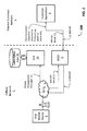
- FIG. 1 this figure illustrates a functional block diagram of a system 100 providing an example operating environment for an embodiment of the technology, with control messages and SMS messages flowing through a cellular network 1 in accordance with international standards.
- the system 100 comprises an external customer network 2 that supports customer applications 3 and that is linked to the cellular network 1.
- the cellular network 1 can comprise a telecommunications carrier network and/or a mobile network.
- the external customer network 2 provides a communication path at or to facilities of a customer.
- the external customer network 2 may comprise a proprietary network belonging to a customer, for example. More generally, the illustrated external customer network 2 can represent a facility or facilities that house one or more customer applications 3 and/or one or more associated communication paths.
- the customer application 3 may comprise a security application, a vehicle tracking application, or a supply chain management application, to mention a few representative examples without limitation.
- the customer application 3 may comprise an application that would need or benefit from a capability to send one or more command and control messages to one or more end mobile devices 8, for example.
- Such a message might comprise an alarm acknowledgement or a location request, for example.
- SMS Short Message Service
- SMS MT Mobile Terminate message
- SMPP Standard Short Message Peer-to-Peer
- the SMSC 5 submits the received SMS MT message 9 to the serving SS7 network 6 over interconnecting SS7 communications links.
- the serving SS7 network 6 attempts to deliver the message to the end mobile device 8 via a wireless telecommunications system 7.
- the SMST MT result 10 from the wireless telecommunications system 7 is delivered to the SMSC 5 over interconnecting SS7 communications links.
- the SMSC 5 sends the SMS MT result 12 of the SMS MT attempt 11 to the customer application 3.
- Mobile management messages 13 are constantly streamed to the serving HLR 14, independent of any other activity, to register presence and location and to authenticate mobile devices 8.
- the HLR 14 has an associated subscription database 76.
- the mobile management messages 13 (e.g., Location Updates) can be integral with the cellular network 1 , without interfacing with applications outside the wireless telecommunications system 7 and associated SS7 network elements.
- the system 100 can be upgraded to support enhanced signaling with the customer application 3.
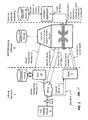
- FIG. 2 this figure illustrates a functional block diagram of another system 200 providing another example operating environment for an embodiment of the technology, wherein an example digital gateway, specifically a computer-based SMS Messaging Gateway 15, is located between a cellular network 1 and an external customer network 2 that comprises a customer application 3.
- an example digital gateway specifically a computer-based SMS Messaging Gateway 15
- a computer-based SMS Messaging Gateway 15 is located between a cellular network 1 and an external customer network 2 that comprises a customer application 3.
- SMS message flow and/or device registration on the system 200 can comprise one or more aspects of the disclosure or teaching provided in U.S. Patent Application No. 13/848,804 , entitled “Method and System for Efficiently Routing Messages," to Bryan Keith Tarleton, Michael J. Criscolo, Edward I. Comer, and William George Simitses.
- the entire contents of U.S. Patent Application No. 13/848,804 are hereby incorporated herein by reference.
- the customer application 3 in the customer network 2 submits an SMS Mobile Terminate message 11 to the SMS messaging gateway 15 via the communications channel 4, typically using standard SMPP protocol.
- the SMS messaging gateway 15 submits the MT message 16 to the SMSC 5 in the cellular network 1, typically using standard SMPP protocol.
- the SMS messaging gateway 15 submits the MT message 17 directly to the wireless telecommunications system 7 using the SS7 network 6.
- the cellular network 1 submits the MT message 17 to the wireless telecommunications system 7 using the SS7 network communications links.
- the wireless telecommunications system 7 attempts to deliver the MT message 17 to the mobile device 8.
- An MT result message 10 from the wireless telecommunications system 7 is delivered to the SMSC 5.
- An MT result message 18 is delivered to the SMS messaging gateway 15 via SS7 communications links.
- An MT result message 19 is delivered to the SMS messaging gateway 15 from the SMSC 5.
- the result of the MT result message 12 is sent to the customer application 3 in the external customer network 2.
- a failed MT queue 78 records devices for future attempts.
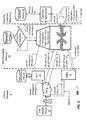
- FIG. 3 this figure illustrates a functional block diagram of an example system 300 in which the system 200 illustrated in Figure 2 has been enhanced to provide real-time SS7 mobile management signaling messages for use by customer applications 3 on the external customer network 2 in accordance with some embodiments of the technology.
- the system 300 illustrated in Figure 3 can be viewed as overlaying an improved signaling technology or process upon the system 200 illustrated in Figure 2 and upon the associated processes discussed above.
- the signaling messages are delivered to the customer application 3 immediately upon receipt from the HLR 14, that is, within approximately one second. If the customer application 3 responds within a few seconds of receipt of the unit ready message by sending an MT message to the mobile device 8 represented by the registration, the likelihood of successful transmission of the MT to the device 8 is high, such as about 90%. In comparison, MT messages sent randomly, without the unit ready notification, typically experience a far lower success ratio, such as about 50%.
- Machine-to-Machine (MTM) applications can use the signaling messages to better manage MT message submission to the wireless telecommunications system 7.
- the signaling messages may indicate that a mobile device 8 is registered and available on the cellular network 1, for example.
- the value of such signaling messages can diminish over time, especially for an MTM service mobile device as compared to a standard cellular mobile device used for cellular telephone service.
- the MTM device may have battery constraints and only power up occasionally and therefore not always be available. Additionally, cellular coverage may be lost as a device moves from one location to another.
- the SMS messaging gateway 15 receives the MT result 18, as discussed above with reference to Figure 2 .
- the SMS messaging gateway 15 inspects the MT result 18. If the result indicates a delivery failure for a registered customer application 3, a mobile device identifier for the associated end mobile device 8 is added to a registration database 22.
- Mobile management messages 13 can be constantly streamed to the HLR 14 independent of any other activity to register presence and location and to authenticate the end mobile devices 8.
- the HLR 14 may stream the mobile management messages 21 via Extensible Markup Language (XML) or other appropriate protocol to the SMS messaging gateway 15.
- the SMS messaging gateway 15 inspects the mobile identification for each of the mobile management messages 21 received from the HLR 14 .
- XML Extensible Markup Language
- the SMS messaging gateway 15 compares the received messages 21 with mobile identifications associated with the customer application 3 that were previously stored in the registration database 22. (See inquiry 77 .) If the SMS messaging gateway 15 matches a mobile identification received from the HLR 14 with a record of the registration database 22, then a unit ready notification message 23 is sent to the customer application 3. (See right "yes" branch from inquiry 77 .) The response of the customer application 3 to receipt of a unit ready notification message 23 can be application dependent. One potential response is that the customer application 3 may use the unit ready notification message 23 to reattempt a previous failed MT 11 message by retrieval from a failed MT queue 78. If the mobile identification is found in the registration database 22, then the record is removed from the registration database 22. (See upper "yes" branch from inquiry 77 .) If the mobile identification received from the HLR 14 does not match a registration record of database 22, then the next mobile management message 21 is retrieved.
- an exemplary SMS messaging gateway comprises a first communication interface for a first communication link to a Home Location Registry (HLR) for a cellular network; a second communication interface for a second communication link to a SS7 network for the cellular network; a third communication interface for a third communication link to a short message service center for the SS7 network; and a fourth communication interface to an external customer network.
- HLR Home Location Registry
- Instructions stored in a memory storage device and executable by a computer can determine if a mobile device is registered based on a mobile message received via the first communication interface. If the mobile device is determined to be registered, the computer can send a unit-ready notification over the fourth communication interface
Abstract
Later, when the mobile device becomes available, the HLR gets notified through registration or location update messages, and notifies the gateway. The gateway then notifies the external application about the availability of the mobile device and removes the past failed SMS delivery from the database.
Description
- The present technology relates generally to communication signaling, and more specifically to a system and method for providing SS7 mobile management signaling messages for use by applications outside an SS7 network.
- Switched telephone network elements are typically networked together with a special purpose data communications network designated Signaling System 7 (SS7). The SS7 network communicates signaling information necessary to set up and manage telephony calls in a separate telecommunications network. SS7 uses what is called out-of band signaling, meaning that signaling (control) information travels on a separate channel, rather than within the same channel as the telephone call. SS7 is a global standard for telecommunications defined by the International Telecommunication Union (ITU) Telecommunication Standardization Sector (ITU-T). The standard specifies procedures and protocol by which network elements in the public switched telephone network (PSTN) exchange information over a digital signaling network to effect wireless (cellular) and wire line call setup, routing, and control. The ITU definition of SS7 allows for national variants such as the American National Standards Institute (ANSI) and Bell Communications Research (Telcordia Technologies) standards used in North America and the European Telecommunications Standards Institute (ETSI) standard used in Europe. The Home Location Register (HLR) is a database element of a SS7 network that contains details of each mobile phone subscriber that is authorized to use the associated network.
- Conventional SS7 functionality in general, and more specifically the HLR SS7 element, constrains mobile management signaling to within the SS7 network. The distribution of such messages beyond the HLR is generally unavailable to applications outside the SS7 network to maintain and manage a database of mobile network status and availability. For example, when a device registers to the mobile network, an 'Update Location' message is typically sent to the HLR to inform of the current mobile location and serving network. This information is stored by the HLR for use subsequently when needed to contact the device. With conventional technology, registration event information is not generally accessible in real time to entities outside the SS7 network. This happens because, with conventional technology, the HLR signaling lacks availability for non-SS7 applications. For instance, an application that needs to communicate with the device can use the registration event to trigger a Mobile Terminate (MT) message.
- In view of the foregoing, a need exists for a capability to provide access to at least a subset of mobile management signaling messages for applications outside of the SS7 network. A technology filling this need, or some related deficiency in the art, would improve communications. For example, such a capability could support or enable a host of services that depend upon knowledge of the real-time status of subscribed mobile devices.
- This and other objects can be achieved by the methods and system as defined in the independent claims. Further enhancements are characterized in the dependent claims.
- HLR mobile management SS7 signaling can be integrated with an application interface to provide mobile management notification. This can be implemented by receiving a real-time feed from the HLR database containing mobile management registration messages (such as Update Location or Ready for SM) and translating the mobile management messages into application notification messages that are delivered to registered applications.
- An application registration database can be utilized where applications designate the mobile devices that will be monitored. Registration can include specific devices or allow for all devices associated with the application. Additionally, the registration process can be integrated with a Short Message Service Center (SMSC), such that when the SMSC detects a specific Mobile Termination failure result for a registered application, the mobile device is automatically added to the registration database. Each mobile management message received from the HLR can be compared to registered devices. If a match occurs, the registration entry for the device can be removed, and the mobile management message translated into an application protocol message and transferred to the application. Thus, the translated message can have a protocol that is compatible with the application. The application can then perform appropriate functionality, for example generate an MT message to contact the device, update an application database, or some other appropriate action or function.
- The foregoing discussion is for illustrative purposes only. Various aspects of the present technology may be more clearly understood and appreciated from a review of the following text and by reference to the associated drawings and the claims that follow. Other aspects, systems, methods, features, advantages, and objects of the present technology will become apparent to one with skill in the art upon examination of the following drawings and text. It is intended that all such aspects, systems, methods, features, advantages, and objects are to be included within this description and covered by this application and by the appended claims of the application.
- Reference will be made below to the accompanying drawings.
-
Figure 1 illustrates a functional block diagram of a system providing an exemplary operating environment for an embodiment of the invention, with control messages and SMS messages flowing through mobile networks in accordance with international standards. -
Figure 2 illustrates a functional block diagram of another system providing another exemplary operating enviromnent for an embodiment of the invention, wherein a digital gateway is located between a cellular network and external applications. -
Figure 3 illustrates a functional block diagram of another system in which the system illustrated inFigure 2 has been enhanced to provide SS7 mobile management signaling messages for use by applications on an external customer network in accordance with exemplary embodiments of the invention. - The drawings illustrate only example embodiments and are therefore not to be considered limiting of the embodiments described. The elements and features shown in the drawings are not necessarily drawn to scale, emphasis instead being placed upon clearly illustrating principles of the embodiments. Additionally, certain dimensions or positionings may be exaggerated to help visually convey certain principles. In the drawings, similar reference numerals among different figures designate like or corresponding, but not necessarily identical, elements.
- Representative embodiments of the technology will be described more fully hereinafter with example reference to the accompanying drawings. The technology may, however, be embodied in many different forms and should not be construed as limited to the embodiments set forth herein; rather, these embodiments are provided so that this disclosure will be thorough and complete, and will fully convey the scope of the technology to those appropriately skilled in the art.
- Turning now to
Figure 1 , this figure illustrates a functional block diagram of asystem 100 providing an example operating environment for an embodiment of the technology, with control messages and SMS messages flowing through acellular network 1 in accordance with international standards. Thesystem 100 comprises anexternal customer network 2 that supportscustomer applications 3 and that is linked to thecellular network 1. In an example embodiment, thecellular network 1 can comprise a telecommunications carrier network and/or a mobile network. - The
external customer network 2 provides a communication path at or to facilities of a customer. Theexternal customer network 2 may comprise a proprietary network belonging to a customer, for example. More generally, the illustratedexternal customer network 2 can represent a facility or facilities that house one ormore customer applications 3 and/or one or more associated communication paths. - The
customer application 3 may comprise a security application, a vehicle tracking application, or a supply chain management application, to mention a few representative examples without limitation. Thecustomer application 3 may comprise an application that would need or benefit from a capability to send one or more command and control messages to one or more endmobile devices 8, for example. Such a message might comprise an alarm acknowledgement or a location request, for example. - In operation, the
customer application 3 in thecustomer network 2 submits a Short Message Service (SMS) Mobile Terminate message (SMS MT) 11 to theSMSC 5 within thecellular network 1 via acommunications channel 4. While thecellular network 1 is illustrated by example, other types of telecommunications networks that may utilize SS7 signaling are supported by the present technology. Standard Short Message Peer-to-Peer (SMPP) protocol may be utilized, for example. TheSMSC 5 submits the receivedSMS MT message 9 to the servingSS7 network 6 over interconnecting SS7 communications links. The serving SS7network 6 attempts to deliver the message to the endmobile device 8 via awireless telecommunications system 7. The SMST MT result 10 from thewireless telecommunications system 7 is delivered to theSMSC 5 over interconnecting SS7 communications links. TheSMSC 5 sends theSMS MT result 12 of theSMS MT attempt 11 to thecustomer application 3.Mobile management messages 13 are constantly streamed to the servingHLR 14, independent of any other activity, to register presence and location and to authenticatemobile devices 8. The HLR 14 has an associatedsubscription database 76. The mobile management messages 13 (e.g., Location Updates) can be integral with thecellular network 1, without interfacing with applications outside thewireless telecommunications system 7 and associated SS7 network elements. As will be discussed in further detail below, thesystem 100 can be upgraded to support enhanced signaling with thecustomer application 3. - Turning now to
Figure 2 , this figure illustrates a functional block diagram of anothersystem 200 providing another example operating environment for an embodiment of the technology, wherein an example digital gateway, specifically a computer-based SMS Messaging Gateway 15, is located between acellular network 1 and anexternal customer network 2 that comprises acustomer application 3. - SMS message flow and/or device registration on the
system 200 can comprise one or more aspects of the disclosure or teaching provided inU.S. Patent Application No. 13/848,804 , entitled "Method and System for Efficiently Routing Messages," to Bryan Keith Tarleton, Michael J. Criscolo, Edward I. Comer, and William George Simitses. The entire contents ofU.S. Patent Application No. 13/848,804 are hereby incorporated herein by reference. - In operation, the
customer application 3 in thecustomer network 2 submits an SMS Mobile Terminatemessage 11 to theSMS messaging gateway 15 via thecommunications channel 4, typically using standard SMPP protocol. TheSMS messaging gateway 15 submits theMT message 16 to theSMSC 5 in thecellular network 1, typically using standard SMPP protocol. TheSMS messaging gateway 15 submits theMT message 17 directly to thewireless telecommunications system 7 using theSS7 network 6. Thecellular network 1 submits theMT message 17 to thewireless telecommunications system 7 using the SS7 network communications links. Thewireless telecommunications system 7 attempts to deliver theMT message 17 to themobile device 8. An MT resultmessage 10 from thewireless telecommunications system 7 is delivered to theSMSC 5. An MT resultmessage 18 is delivered to theSMS messaging gateway 15 via SS7 communications links. An MT resultmessage 19 is delivered to theSMS messaging gateway 15 from theSMSC 5. The result of theMT result message 12 is sent to thecustomer application 3 in theexternal customer network 2. A failedMT queue 78 records devices for future attempts. - Turning now to
Figure 3 , this figure illustrates a functional block diagram of anexample system 300 in which thesystem 200 illustrated inFigure 2 has been enhanced to provide real-time SS7 mobile management signaling messages for use bycustomer applications 3 on theexternal customer network 2 in accordance with some embodiments of the technology. Thesystem 300 illustrated inFigure 3 can be viewed as overlaying an improved signaling technology or process upon thesystem 200 illustrated inFigure 2 and upon the associated processes discussed above. - With real-time mobile management signaling messages, the signaling messages are delivered to the
customer application 3 immediately upon receipt from theHLR 14, that is, within approximately one second. If thecustomer application 3 responds within a few seconds of receipt of the unit ready message by sending an MT message to themobile device 8 represented by the registration, the likelihood of successful transmission of the MT to thedevice 8 is high, such as about 90%. In comparison, MT messages sent randomly, without the unit ready notification, typically experience a far lower success ratio, such as about 50%. - Numerous applications can benefit from the improved signaling provided by the
system 300. For example, Machine-to-Machine (MTM) applications can use the signaling messages to better manage MT message submission to thewireless telecommunications system 7. The signaling messages may indicate that amobile device 8 is registered and available on thecellular network 1, for example. The value of such signaling messages can diminish over time, especially for an MTM service mobile device as compared to a standard cellular mobile device used for cellular telephone service. The MTM device may have battery constraints and only power up occasionally and therefore not always be available. Additionally, cellular coverage may be lost as a device moves from one location to another. - In operation, the
SMS messaging gateway 15 receives theMT result 18, as discussed above with reference toFigure 2 . When theMT result 18 is received, theSMS messaging gateway 15 inspects theMT result 18. If the result indicates a delivery failure for a registeredcustomer application 3, a mobile device identifier for the associated endmobile device 8 is added to aregistration database 22.Mobile management messages 13 can be constantly streamed to theHLR 14 independent of any other activity to register presence and location and to authenticate the endmobile devices 8. TheHLR 14 may stream themobile management messages 21 via Extensible Markup Language (XML) or other appropriate protocol to theSMS messaging gateway 15. TheSMS messaging gateway 15 inspects the mobile identification for each of themobile management messages 21 received from theHLR 14. Via this inspection, theSMS messaging gateway 15 compares the receivedmessages 21 with mobile identifications associated with thecustomer application 3 that were previously stored in theregistration database 22. (Seeinquiry 77.) If theSMS messaging gateway 15 matches a mobile identification received from theHLR 14 with a record of theregistration database 22, then a unitready notification message 23 is sent to thecustomer application 3. (See right "yes" branch frominquiry 77.) The response of thecustomer application 3 to receipt of a unitready notification message 23 can be application dependent. One potential response is that thecustomer application 3 may use the unitready notification message 23 to reattempt a previous failedMT 11 message by retrieval from a failedMT queue 78. If the mobile identification is found in theregistration database 22, then the record is removed from theregistration database 22. (See upper "yes" branch frominquiry 77.) If the mobile identification received from theHLR 14 does not match a registration record ofdatabase 22, then the nextmobile management message 21 is retrieved. - In view of the foregoing, it will be understood that an exemplary SMS messaging gateway comprises a first communication interface for a first communication link to a Home Location Registry (HLR) for a cellular network; a second communication interface for a second communication link to a SS7 network for the cellular network; a third communication interface for a third communication link to a short message service center for the SS7 network; and a fourth communication interface to an external customer network. Instructions stored in a memory storage device and executable by a computer, can determine if a mobile device is registered based on a mobile message received via the first communication interface. If the mobile device is determined to be registered, the computer can send a unit-ready notification over the fourth communication interface
- Many modifications and other embodiments of the disclosures set forth herein will come to mind to one skilled in the art to which these disclosures pertain who has the benefit of the teachings presented in the foregoing descriptions and the associated drawings. Therefore, it is to be understood that the disclosures are not to be limited to the specific embodiments disclosed. Although specific terms are employed herein, they are used in a generic and descriptive sense only and not for purposes of limitation.
Claims (15)
- A method comprising the steps of:by a digital gateway, maintaining a database that associates mobile devices with a customer application;by the digital gateway, receiving a plurality of mobile management messages from a home location register (HLR);by the digital gateway, comparing a mobile management message from the plurality of mobile management messages with the database to determine whether the mobile management message is associated with one of the mobile devices; andby the digital gateway, if the mobile management message is determined to be associated with the one of the mobile devices, sending notification to the customer application that the one of the mobile devices is available.
- The method of Claim 1, wherein the customer application resides on an external customer network.
- The method of Claim 1 or 2, further comprising the step of
by the digital gateway, if the mobile management message is determined to be associated with the one of the mobile devices, updating the database. - The method according to one of the preceding claims, wherein the step of sending notification to the customer application comprises translating the mobile management message into an application notification message.
- The method according to one of the preceding claims 1-3, wherein the step of sending notification to the customer application comprises translating the mobile management message into a format compatible with the customer application.
- The method according to one of the preceding claims, wherein the digital gateway comprises a messaging gateway that connects a plurality of customer networks to at least one cellular network.
- The method according to one of the preceding claims, further comprising the steps of:by the gateway, receiving SMS MT results via SS7; andby the gateway, receiving SMS MT results from a short message service center (SMSC).
- A method comprising:receiving a mobile terminate (MT) result at a gateway;determining, at the gateway, whether the received MT result indicates a delivery failure for an application; andif the delivery failure is indicated, then including in a registration database at the gateway a mobile device identifier that is associated with the MT result.
- The method of Claim 8, wherein the application comprises a registered customer application.
- The method of Claim 8 or 9, wherein the gateway provides an interface between one or more cellular networks and one or more external customer networks.
- The method according to one of the preceding claims 8-10, further comprising the step of
at the gateway, translating a mobile management message into an application notification message having a protocol compatible with the application. - An SMS messaging gateway comprising:a first communication interface for a first communication link to a Home Location Registry (HLR) for a cellular network;a second communication interface for a second communication link to a SS7 network for the cellular network;a third communication interface for a third communication link to a short message service center for the SS7 network;a fourth communication interface to an external customer network; andcomputer-executable instructions stored in a memory storage device for:determining if a mobile device is registered based on a mobile message received via the first communication interface; andif the mobile device is determined to be registered, sending a unit-ready notification over the fourth communication interface.
- The SMS messaging gateway of Claim 12, further comprising a registration database.
- The SMS messaging gateway of Claim 12 or 13,
wherein the SMS messaging gateway further comprises a database, and
wherein the computer-executable instructions further comprise instructions for updating data of the database if the mobile device is determined to be registered. - The SMS messaging gateway according to one of the preceding claims 12-14, wherein the first communication interface is operative to receive a stream of mobile management messages from the HLR and to inspect each mobile management message in the stream in real time.
Applications Claiming Priority (2)
| Application Number | Priority Date | Filing Date | Title |
|---|---|---|---|
| US201461929643P | 2014-01-21 | 2014-01-21 | |
| US14/272,709 US9510180B2 (en) | 2014-01-21 | 2014-05-08 | Mobile management message distribution and active on-network determination |
Publications (2)
| Publication Number | Publication Date |
|---|---|
| EP2897393A2 true EP2897393A2 (en) | 2015-07-22 |
| EP2897393A3 EP2897393A3 (en) | 2015-11-04 |
Family
ID=52434554
Family Applications (1)
| Application Number | Title | Priority Date | Filing Date |
|---|---|---|---|
| EP15151837.0A Withdrawn EP2897393A3 (en) | 2014-01-21 | 2015-01-20 | Mobile management message distribution and active on-network determination |
Country Status (3)
| Country | Link |
|---|---|
| US (1) | US9510180B2 (en) |
| EP (1) | EP2897393A3 (en) |
| CA (1) | CA2877661A1 (en) |
Cited By (3)
| Publication number | Priority date | Publication date | Assignee | Title |
|---|---|---|---|---|
| CN107148007A (en) * | 2017-05-05 | 2017-09-08 | 四川长虹电器股份有限公司 | The short message service United Dispatching method of compatible multi-operator gateway |
| CN107371127A (en) * | 2017-08-22 | 2017-11-21 | 四川长虹电器股份有限公司 | Bluetooth equipment management by synchronization implementation method under Android system difference operational mode |
| CN109151800A (en) * | 2017-06-15 | 2019-01-04 | 华为技术有限公司 | Communication means and equipment |
Families Citing this family (1)
| Publication number | Priority date | Publication date | Assignee | Title |
|---|---|---|---|---|
| US9965525B2 (en) * | 2015-04-09 | 2018-05-08 | At&T Mobility Ii Llc | Protecting personal data |
Family Cites Families (9)
| Publication number | Priority date | Publication date | Assignee | Title |
|---|---|---|---|---|
| US7522911B2 (en) | 2000-04-11 | 2009-04-21 | Telecommunication Systems, Inc. | Wireless chat automatic status tracking |
| KR100501157B1 (en) * | 2002-08-26 | 2005-07-18 | 에스케이 텔레콤주식회사 | Address Process Method For Short Message Service Center In WCDMA Network |
| SG106670A1 (en) * | 2003-02-18 | 2004-10-29 | Chikka Pte Ltd | A messaging system and method therefor |
| US8738046B2 (en) * | 2008-06-19 | 2014-05-27 | Numerex Corp. | Intelligent short message delivery system and method |
| WO2010068506A2 (en) * | 2008-11-25 | 2010-06-17 | Tekelec | Methods, systems, and computer program products for providing first delivery attempt service for short message peer-to-peer (smpp) messages |
| US8325642B1 (en) * | 2009-05-14 | 2012-12-04 | Cellco Partnership | Redirection of message from mobile station based on identity of mobile station |
| US9241202B2 (en) * | 2009-10-09 | 2016-01-19 | Tekelec, Inc. | Methods, systems, and computer readable media for dynamically and conditionally setting service triggers in a communications network |
| US8549083B2 (en) * | 2010-01-06 | 2013-10-01 | Alcatel Lucent | Message waiting notification to external message centers |
| US8391899B2 (en) * | 2010-03-16 | 2013-03-05 | Alcatel Lucent | Text message delivery to a mobile device in a wireless communication network |
-
2014
- 2014-05-08 US US14/272,709 patent/US9510180B2/en active Active
-
2015
- 2015-01-13 CA CA2877661A patent/CA2877661A1/en not_active Abandoned
- 2015-01-20 EP EP15151837.0A patent/EP2897393A3/en not_active Withdrawn
Cited By (4)
| Publication number | Priority date | Publication date | Assignee | Title |
|---|---|---|---|---|
| CN107148007A (en) * | 2017-05-05 | 2017-09-08 | 四川长虹电器股份有限公司 | The short message service United Dispatching method of compatible multi-operator gateway |
| CN109151800A (en) * | 2017-06-15 | 2019-01-04 | 华为技术有限公司 | Communication means and equipment |
| CN107371127A (en) * | 2017-08-22 | 2017-11-21 | 四川长虹电器股份有限公司 | Bluetooth equipment management by synchronization implementation method under Android system difference operational mode |
| CN107371127B (en) * | 2017-08-22 | 2019-11-12 | 四川长虹电器股份有限公司 | Bluetooth equipment management by synchronization implementation method under Android system difference operational mode |
Also Published As
| Publication number | Publication date |
|---|---|
| US9510180B2 (en) | 2016-11-29 |
| CA2877661A1 (en) | 2015-07-21 |
| EP2897393A3 (en) | 2015-11-04 |
| US20150208229A1 (en) | 2015-07-23 |
Similar Documents
| Publication | Publication Date | Title |
|---|---|---|
| US7873345B1 (en) | Over-the-air service termination for a telematics device | |
| CN101194523B (en) | The method of the message that messaging delivery services transmits, system and computer program in monitor communications network | |
| EP1142379B1 (en) | Voice mail notification service between mobile communication systems | |
| US7962160B2 (en) | Method, system and short message service center for getting user equipment information through short messages | |
| US8725107B2 (en) | Method for sending emergency messages to mobile terminals | |
| US20040005875A1 (en) | Method of furnishing illegal mobile equipment user information | |
| WO2008146097A1 (en) | A method for the forwarding of sms in a mobile communication system | |
| EP2897393A2 (en) | Mobile management message distribution and active on-network determination | |
| US20080153455A1 (en) | System, method and program for managing voip calls such as 911 calls from mobile devices | |
| WO2002056611A2 (en) | Method for short message service forwarding delivery | |
| US8260314B2 (en) | Business hour notification delivery | |
| US20070118647A1 (en) | Message identification, correlation, recipient authentication, and reception confirmation in multi-event and multi-media environments | |
| US8229414B1 (en) | Release of temporarily allocated number triggered by voice disconnect at mobile switching center | |
| CN100417298C (en) | Mobile communication control method and mobile communication system | |
| CN114710757B (en) | Information processing method, network side equipment and terminal | |
| CN111565235A (en) | Method and device for obtaining address of multimedia message service server | |
| CN102625262A (en) | Incoming-call reminding method, device and system | |
| WO2005004453A1 (en) | Ring-back tone service system and the method | |
| US20090037540A1 (en) | Notification of waiting voicemail messages between different types of communication networks | |
| US6615036B1 (en) | Method and apparatus for storing data within a communication system | |
| CN104125552A (en) | Network transmission principle based number transmission achieving method and system | |
| US20050186943A1 (en) | System and method for voicemail retrieval notification | |
| US20050239442A1 (en) | Method and system for handling wireless messaging errors | |
| CN1454427B (en) | Method and system for re-routing a call | |
| FI113437B (en) | Checking the validity of a subscriber connection in a telecommunications system |
Legal Events
| Date | Code | Title | Description |
|---|---|---|---|
| PUAI | Public reference made under article 153(3) epc to a published international application that has entered the european phase |
Free format text: ORIGINAL CODE: 0009012 |
|
| 17P | Request for examination filed |
Effective date: 20150120 |
|
| AK | Designated contracting states |
Kind code of ref document: A2 Designated state(s): AL AT BE BG CH CY CZ DE DK EE ES FI FR GB GR HR HU IE IS IT LI LT LU LV MC MK MT NL NO PL PT RO RS SE SI SK SM TR |
|
| AX | Request for extension of the european patent |
Extension state: BA ME |
|
| PUAL | Search report despatched |
Free format text: ORIGINAL CODE: 0009013 |
|
| AK | Designated contracting states |
Kind code of ref document: A3 Designated state(s): AL AT BE BG CH CY CZ DE DK EE ES FI FR GB GR HR HU IE IS IT LI LT LU LV MC MK MT NL NO PL PT RO RS SE SI SK SM TR |
|
| AX | Request for extension of the european patent |
Extension state: BA ME |
|
| RIC1 | Information provided on ipc code assigned before grant |
Ipc: H04W 88/16 20090101ALN20150930BHEP Ipc: H04W 88/18 20090101ALI20150930BHEP Ipc: H04W 8/10 20090101AFI20150930BHEP Ipc: H04W 4/14 20090101ALI20150930BHEP Ipc: H04W 4/12 20090101ALN20150930BHEP |
|
| STAA | Information on the status of an ep patent application or granted ep patent |
Free format text: STATUS: THE APPLICATION IS DEEMED TO BE WITHDRAWN |
|
| 18D | Application deemed to be withdrawn |
Effective date: 20160505 |