EP2897381A1 - Oscillator and electronic device - Google Patents
Oscillator and electronic device Download PDFInfo
- Publication number
- EP2897381A1 EP2897381A1 EP15153584.6A EP15153584A EP2897381A1 EP 2897381 A1 EP2897381 A1 EP 2897381A1 EP 15153584 A EP15153584 A EP 15153584A EP 2897381 A1 EP2897381 A1 EP 2897381A1
- Authority
- EP
- European Patent Office
- Prior art keywords
- piezoelectric element
- vibration member
- oscillator
- frame
- resonance frequency
- Prior art date
- Legal status (The legal status is an assumption and is not a legal conclusion. Google has not performed a legal analysis and makes no representation as to the accuracy of the status listed.)
- Withdrawn
Links
Images



Classifications
-
- B—PERFORMING OPERATIONS; TRANSPORTING
- B06—GENERATING OR TRANSMITTING MECHANICAL VIBRATIONS IN GENERAL
- B06B—METHODS OR APPARATUS FOR GENERATING OR TRANSMITTING MECHANICAL VIBRATIONS OF INFRASONIC, SONIC, OR ULTRASONIC FREQUENCY, e.g. FOR PERFORMING MECHANICAL WORK IN GENERAL
- B06B1/00—Methods or apparatus for generating mechanical vibrations of infrasonic, sonic, or ultrasonic frequency
- B06B1/02—Methods or apparatus for generating mechanical vibrations of infrasonic, sonic, or ultrasonic frequency making use of electrical energy
- B06B1/06—Methods or apparatus for generating mechanical vibrations of infrasonic, sonic, or ultrasonic frequency making use of electrical energy operating with piezoelectric effect or with electrostriction
- B06B1/0644—Methods or apparatus for generating mechanical vibrations of infrasonic, sonic, or ultrasonic frequency making use of electrical energy operating with piezoelectric effect or with electrostriction using a single piezoelectric element
-
- G—PHYSICS
- G10—MUSICAL INSTRUMENTS; ACOUSTICS
- G10K—SOUND-PRODUCING DEVICES; METHODS OR DEVICES FOR PROTECTING AGAINST, OR FOR DAMPING, NOISE OR OTHER ACOUSTIC WAVES IN GENERAL; ACOUSTICS NOT OTHERWISE PROVIDED FOR
- G10K9/00—Devices in which sound is produced by vibrating a diaphragm or analogous element, e.g. fog horns, vehicle hooters or buzzers
- G10K9/12—Devices in which sound is produced by vibrating a diaphragm or analogous element, e.g. fog horns, vehicle hooters or buzzers electrically operated
- G10K9/122—Devices in which sound is produced by vibrating a diaphragm or analogous element, e.g. fog horns, vehicle hooters or buzzers electrically operated using piezoelectric driving means
-
- H—ELECTRICITY
- H04—ELECTRIC COMMUNICATION TECHNIQUE
- H04R—LOUDSPEAKERS, MICROPHONES, GRAMOPHONE PICK-UPS OR LIKE ACOUSTIC ELECTROMECHANICAL TRANSDUCERS; ELECTRIC HEARING AIDS; PUBLIC ADDRESS SYSTEMS
- H04R17/00—Piezoelectric transducers; Electrostrictive transducers
- H04R17/10—Resonant transducers, i.e. adapted to produce maximum output at a predetermined frequency
-
- H—ELECTRICITY
- H10—SEMICONDUCTOR DEVICES; ELECTRIC SOLID-STATE DEVICES NOT OTHERWISE PROVIDED FOR
- H10N—ELECTRIC SOLID-STATE DEVICES NOT OTHERWISE PROVIDED FOR
- H10N30/00—Piezoelectric or electrostrictive devices
- H10N30/80—Constructional details
- H10N30/85—Piezoelectric or electrostrictive active materials
- H10N30/857—Macromolecular compositions
-
- H—ELECTRICITY
- H10—SEMICONDUCTOR DEVICES; ELECTRIC SOLID-STATE DEVICES NOT OTHERWISE PROVIDED FOR
- H10N—ELECTRIC SOLID-STATE DEVICES NOT OTHERWISE PROVIDED FOR
- H10N30/00—Piezoelectric or electrostrictive devices
- H10N30/80—Constructional details
- H10N30/88—Mounts; Supports; Enclosures; Casings
-
- H—ELECTRICITY
- H04—ELECTRIC COMMUNICATION TECHNIQUE
- H04R—LOUDSPEAKERS, MICROPHONES, GRAMOPHONE PICK-UPS OR LIKE ACOUSTIC ELECTROMECHANICAL TRANSDUCERS; ELECTRIC HEARING AIDS; PUBLIC ADDRESS SYSTEMS
- H04R2217/00—Details of magnetostrictive, piezoelectric, or electrostrictive transducers covered by H04R15/00 or H04R17/00 but not provided for in any of their subgroups
- H04R2217/03—Parametric transducers where sound is generated or captured by the acoustic demodulation of amplitude modulated ultrasonic waves
Definitions
- the present invention relates to an oscillator and an electronic device.
- Oscillators using a piezoelectric material are used as, for example, a parametric speaker, or an oscillation source of an ultrasonic wave sensor.
- Patent Document 1 discloses that a circular piezoelectric element is divided into a plurality of regions in a radial direction, and a signal is directly input to each of the divided regions.
- Patent Document 2 discloses that an electrode formed on a piezoelectric film is one-dimensionally divided into a plurality of parts.
- Patent Document 3 discloses that four corners of a rectangular piezoelectric plate formed of lithium niobate are supported by a metal supporting plate that protrudes from an internal wall of a supporting frame.
- Patent Document 4 discloses that a metal vibrating plate and a piezoelectric ceramic plate are fixed to a center portion of a foamed resin sheet, and a rigid frame is fixed to an edge of the foamed resin sheet.
- the oscillator When the oscillator is used as a parametric speaker or an oscillation source of an ultrasonic wave sensor, the oscillator is required to obtain a large output with a resonance frequency.
- An object of the invention is to provide an oscillator and an electronic device that can obtain a large output with a resonance frequency.
- an oscillator including a vibration member; a piezoelectric element that is attached to the vibration member; a plurality of electrodes that are provided on one surface of the piezoelectric element and are two-dimensionally arranged so as to be spaced apart from each other; a supporting member that supports an edge of the vibration member; and a control unit that inputs an independent driving signal to each of the plurality of electrodes.
- an oscillator including a vibration member; a piezoelectric element that is attached to the vibration member; a plurality of electrodes that are provided on one surface of the piezoelectric element and are two-dimensionally arranged so as to be spaced apart from each other; and a frame to which the vibration member is fixed.
- a plane of an inner circumference of the frame has a polygonal shape of which all corners have an angle that is equal to or less than 180 degrees when seen in a plan view.
- At least one of corners of the frame has a reinforcing member that is fixed to the frame and the vibration member.
- FIG. 1 is a diagram illustrating a configuration of an oscillator according to a first embodiment.
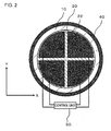
- FIG. 2 is a plan view of the oscillator illustrated in FIG. 1 .
- the oscillator has a vibration member 10, a piezoelectric element 20, a supporting member (a supporting frame) 40, and a control unit 50.
- the piezoelectric element 20 is attached to the vibration member 10.
- a plurality of electrodes 22 are two-dimensionally arranged on one surface of the piezoelectric element 20 so as to be spaced apart from each other.
- the supporting frame 40 supports an edge of the vibration member 10.
- the control unit 50 inputs an independent driving signal to each of the plurality of electrodes 22. For this reason, it is possible to obtain a large output with a resonance frequency depending on what signal is input to which electrode 22.
- it will be described in detail.
- the vibration member 10 has a sheet shape, and vibrates through the vibration generated from the piezoelectric element 20.
- the vibration member 10 adjusts a fundamental resonance frequency of the piezoelectric element 20.
- a fundamental resonance frequency of a mechanical vibrator depends on load weight and compliance. Since the compliance is a mechanical rigidity of a vibrator, the fundamental resonance frequency of the piezoelectric element 20 can be controlled by controlling the rigidity of the vibration member 10.
- the thickness of the vibration member 10 is preferably equal to or more than 5 ⁇ m and equal to or less than 500 ⁇ m.
- the vibration member 10 has a longitudinal elastic modulus, which is an index indicating rigidity, of equal to or more than 1 Gpa and equal to or less than 500 GPa.
- the material constituting the vibration member 10 is not particularly limited as long as it is a material, such as a metal or a resin, having a high elastic modulus with respect to the piezoelectric element 20 which is formed of a brittle material, but is preferably phosphor bronze, stainless steel or the like from the viewpoint of workability or costs.
- the piezoelectric element 20 is, for example, a resin film that is formed of a high molecular material indicating a piezoelectric property.
- the piezoelectric element 20 is formed of, for example, polyvinylidene fluoride, but the invention is not limited thereto.
- the piezoelectric element 20 may be formed of piezoelectric ceramics such as PZT. In any of the above cases, the planar shape of the piezoelectric element 20 is smaller than that of the vibration member 10.
- the plurality of electrodes 22 are two-dimensionally arranged on one surface of the piezoelectric element 20 so as to be spaced apart from each other.
- the piezoelectric element 20 is virtually divided into a plurality of regions in an X direction and a Y direction.
- the electrode 22 is formed in each of the divided regions. It is preferable that the regions have the same planar shape. In this case, it is preferable that the electrodes 22 have the same planar shape and that the electrodes 22 be arranged at equal intervals. In addition, it is preferable that at least some of the electrodes 22 be arranged so as to be point-symmetrical to each other based on the center of the piezoelectric element 20.
- the planar shape of the piezoelectric element 20 is circular.
- the vibration member 10 also has a circular shape
- the supporting frame 40 also has a shape along the circumference of the vibration member.
- the vibration member 10, the piezoelectric element 20, and the supporting frame 40 are disposed so as to be concentric with each other.
- the piezoelectric element 20 is virtually divided at equal angles (for example, 90 degrees) in a circumferential direction based on the center of the piezoelectric element 20.
- the fan-like electrode 22 is provided in each of the divided regions.
- the piezoelectric element 20 is virtually divided into two equal parts when seen in a cross-section passing through the center of the piezoelectric element 20, and the electrode 22 is provided in each of the regions.
- a ground electrode may be provided on the entirety of the other surface of the piezoelectric element 20, and the ground electrode may be provided in the form of an island only in a portion overlapping the electrode 22 when seen in a plan view.
- the control unit 50 inputs an independent driving signal to each of the plurality of electrodes 22.
- the control unit 50 modulates sound data that is input from the outside to generate the modulated data for the parametric speaker, generates an oscillation signal based on the modulated data, and inputs the oscillation signal to the piezoelectric element 20.
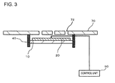
- FIG. 3 is a diagram illustrating a state where the oscillator illustrated in FIG. 2 is attached to an electronic device.
- the oscillator is attached to an internal wall of a housing 70 of the electronic device.
- a top surface of the supporting frame 40 is attached to the internal wall of the housing 70.
- the housing 70 is provided with sound holes 72.
- the supporting frame 40 includes the sound holes 72 on the inside thereof when seen in a plan view. For this reason, the sound holes 72 face the vibration member 10 and the piezoelectric element 20, and a sound wave oscillated from the vibration member 10 and the piezoelectric element 20 is radiated to the outside of the housing 70 through the sound holes 72.
- the control unit 50 inputs a driving signal having a fundamental resonance frequency to all the electrodes 22 in the same phase. Then, the vibration member 10 and the piezoelectric element 20 vibrate with the fundamental resonance frequency.
- the control unit 50 when a sound wave having a second-order resonance frequency of the vibration member 10 and the piezoelectric element 20 is output from the oscillator, the control unit 50 outputs a driving signal having the second-order resonance frequency to two adjacent electrodes 22 in opposite phases.
- driving signals having opposite phases are input to the two adjacent electrodes 22 in the X direction or in the Y direction in the drawing.
- the piezoelectric element 20 has a high mechanical quality factor Q, when the vibration member 10 and the piezoelectric element 20 are vibrating, there is a tendency for a high order resonance frequency to be generated together with a fundamental resonance frequency in the piezoelectric element 20 due to the divided vibration.
- a high order resonance frequency is generated together with the fundamental resonance frequency, a sound wave is cancelled out between the high order resonance frequency and the fundamental resonance frequency.
- the output efficiency of the piezoelectric element 20 decreases.
- a second-order resonance frequency is intentionally generated, such a decrease in efficiency can be prevented.
- a large output can be obtained with a second or more-order resonance frequency. This effect can also be obtained in a case where the piezoelectric element 20 is formed of a high molecular material.
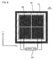
- FIG. 4 is a plan view illustrating a configuration of an oscillator according to a second embodiment and corresponds to FIG. 2 according to the first embodiment.
- the oscillator according to the embodiment has the same configuration as the oscillator according to the first embodiment, except for the planar shapes of the vibration member 10, the piezoelectric element 20, the electrode 22, and the supporting frame 40.
- the planar shapes of the piezoelectric element 20 and the vibration member 10 are rectangular.
- the piezoelectric element 20 is virtually divided into equal parts in the X direction and the Y direction. In other words, the divided regions in the piezoelectric element 20 have the same shape.
- the electrode 22 having a rectangular shape is provided in each of the divided regions.
- the electrode 22 has a similar shape to the region after the piezoelectric element 20 is virtually divided.
- the piezoelectric element 20 may be divided into three or more equal parts.
- the oscillator can oscillate a third or more-order resonance frequency with a high efficiency.
- a number of divisions in the X direction and a number of divisions in the Y direction may be the same or different from each other. Meanwhile, in any of the above cases, it is preferable that the electrodes 22 be disposed at equal intervals.
- the supporting frame 40 has a shape along a rectangular edge.
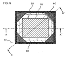
- FIG. 5 is a plan view illustrating a configuration of an oscillator according to a third embodiment.
- FIG. 6 is a cross-sectional view taken along line A-A' of FIG. 5 .
- FIG. 7 is a cross-sectional view taken along line B-B' of FIG. 5 .
- the oscillator has the same configuration as the oscillator according to the first embodiment except for the following configuration.
- the plane of the inner circumference of the supporting frame 40 has a polygonal shape of which all corners have an angle that is equal to or less than 180 degrees.
- a reinforcing member 60 is provided at one or more corners of the supporting frame 40. As illustrated in FIG. 7 , the reinforcing member 60 is fixed to the supporting frame 40 and the vibration member 10. Hereinafter, it will be described in detail.
- the vibration member 10 is fixed to one surface of the supporting member 30.
- the supporting member 30 is formed of a metal, for example, stainless steel or phosphor bronze.
- the planar shape of the supporting member 30 is larger than the vibration member 10.
- the supporting member 30 is fixed to the supporting frame 40.
- the vibration member 10 is fixed to the supporting frame 40 through the supporting member 30.
- the vibration member 10, the piezoelectric element 20, and the supporting member 30 vibrate as a vibrating element.
- the supporting frame 40 has a shape along a rectangular edge.
- the shape of the supporting frame 40 is not limited thereto.
- the supporting frame 40 may have a regular polygonal shape.
- the reinforcing member 60 is fixed to the supporting frame 40 and the vibration member 10.
- the reinforcing member 60 is provided at all corners of the supporting frame 40.
- the reinforcing members 60 are spaced apart from each other, and do not have any portions which are connected to each other.
- the reinforcing member 60 may be fixed to the supporting member 30 instead of the vibration member 10.
- a distance between the reinforcing member 60 and the piezoelectric element 20 is preferably as short as possible.
- the planar shape of the inner circumference of the supporting frame 40 changes by providing the reinforcing members 60.
- the reinforcing member 60 has a shape in which the inner circumference of the supporting frame 40 comes close to a circle.
- the reinforcing member 60 is disposed in such a manner that the planar shape thereof is an isosceles triangle in which a vertex angle thereof is equal to an inner angle of the supporting frame 40, and that the vertex angle overlaps the corner of the supporting frame 40.
- an electrode provided in the piezoelectric element 20 may be the same as in the first embodiment and may not be divided.
- the width of the vibrating element is not determined to be one.
- the width of the vibrating element is maximum in line B-B' and is minimum in line A-A'.
- the reinforcing member is provided at the corners of the supporting frame 40, it is possible to reduce the difference between a maximum value and a minimum value of the width of the vibrating element. Therefore, it is possible to prevent the output efficiency of the piezoelectric element 20 from decreasing.
- the reinforcing member 60 may be attached to the supporting member 30.
- the reinforcing member 60 may be attached to a surface of the supporting member 30 on which the vibration member 10 is not provided.
- the vibration member 10 may be directly fixed to the supporting frame 40 without providing the supporting member 30.
- the reinforcing member 60 may be formed integrally with the vibration member 10.
- the portion of the vibration member 10 which is located at the corner of the supporting frame 40 is thicker than other portions. The thick portion serves as the reinforcing member 60.
Landscapes
- Engineering & Computer Science (AREA)
- Physics & Mathematics (AREA)
- Acoustics & Sound (AREA)
- Multimedia (AREA)
- Mechanical Engineering (AREA)
- Signal Processing (AREA)
- Spectroscopy & Molecular Physics (AREA)
- Circuit For Audible Band Transducer (AREA)
- Piezo-Electric Transducers For Audible Bands (AREA)
- Transducers For Ultrasonic Waves (AREA)
- Piezo-Electric Or Mechanical Vibrators, Or Delay Or Filter Circuits (AREA)
Abstract
Description
- The present invention relates to an oscillator and an electronic device.
- Oscillators using a piezoelectric material are used as, for example, a parametric speaker, or an oscillation source of an ultrasonic wave sensor.
- Patent Document 1 discloses that a circular piezoelectric element is divided into a plurality of regions in a radial direction, and a signal is directly input to each of the divided regions. Patent Document 2 discloses that an electrode formed on a piezoelectric film is one-dimensionally divided into a plurality of parts.
- In addition, Patent Document 3 discloses that four corners of a rectangular piezoelectric plate formed of lithium niobate are supported by a metal supporting plate that protrudes from an internal wall of a supporting frame. Patent Document 4 discloses that a metal vibrating plate and a piezoelectric ceramic plate are fixed to a center portion of a foamed resin sheet, and a rigid frame is fixed to an edge of the foamed resin sheet.
-
- [Patent Document 1] Japanese Unexamined Utility Model Registration Publication No.
62-10594 - [Patent Document 2] Japanese Unexamined Patent Publication No.
2003-143694 - [Patent Document 3] Japanese Unexamined Patent Publication No.
7-106660 - [Patent Document 4] Japanese Unexamined Patent Publication No.
3-201800 - When the oscillator is used as a parametric speaker or an oscillation source of an ultrasonic wave sensor, the oscillator is required to obtain a large output with a resonance frequency.
- An object of the invention is to provide an oscillator and an electronic device that can obtain a large output with a resonance frequency.
- According to the invention, there is provided an oscillator including a vibration member; a piezoelectric element that is attached to the vibration member; a plurality of electrodes that are provided on one surface of the piezoelectric element and are two-dimensionally arranged so as to be spaced apart from each other; a supporting member that supports an edge of the vibration member; and a control unit that inputs an independent driving signal to each of the plurality of electrodes.
- According to the invention, there is provided an oscillator including a vibration member; a piezoelectric element that is attached to the vibration member; a plurality of electrodes that are provided on one surface of the piezoelectric element and are two-dimensionally arranged so as to be spaced apart from each other; and a frame to which the vibration member is fixed. A plane of an inner circumference of the frame has a polygonal shape of which all corners have an angle that is equal to or less than 180 degrees when seen in a plan view. At least one of corners of the frame has a reinforcing member that is fixed to the frame and the vibration member.
- According to the invention, it is possible to obtain a large output with a resonance frequency.
- The above-described objects, other objects, features and advantages will be further apparent from the preferred embodiments described below, and the accompanying drawings as follows.
-
FIG. 1 is a diagram illustrating a configuration of an oscillator according to a first embodiment. -
FIG. 2 is a plan view of the oscillator illustrated inFIG. 1 . -
FIG. 3 is a diagram illustrating a state where the oscillator illustrated inFIG. 2 is attached to an electronic device. -
FIG. 4 is a plan view illustrating a configuration of an oscillator according to a second embodiment. -
FIG. 5 is a plan view illustrating a configuration of an oscillator according to a third embodiment. -
FIG. 6 is a cross-sectional view taken along line A-A' ofFIG. 5 . -
FIG. 7 is a cross-sectional view taken along line B-B' ofFIG. 5 . -
FIG. 8 is a cross-sectional view illustrating a modified example ofFIG. 7 . -
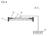
FIG. 9 is a cross-sectional view illustrating a modified example ofFIG. 7 . -
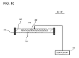
FIG. 10 is a cross-sectional view illustrating a modified example ofFIG. 7 . - Hereinafter, embodiments of the invention will be described with reference to the accompanying drawings. In addition, in all the drawings, the same component is denoted by the same reference numeral and description will not be repeated.
-
FIG. 1 is a diagram illustrating a configuration of an oscillator according to a first embodiment.FIG. 2 is a plan view of the oscillator illustrated inFIG. 1 . The oscillator has avibration member 10, apiezoelectric element 20, a supporting member (a supporting frame) 40, and acontrol unit 50. Thepiezoelectric element 20 is attached to thevibration member 10. A plurality ofelectrodes 22 are two-dimensionally arranged on one surface of thepiezoelectric element 20 so as to be spaced apart from each other. The supportingframe 40 supports an edge of thevibration member 10. Thecontrol unit 50 inputs an independent driving signal to each of the plurality ofelectrodes 22. For this reason, it is possible to obtain a large output with a resonance frequency depending on what signal is input to whichelectrode 22. Hereinafter, it will be described in detail. - The
vibration member 10 has a sheet shape, and vibrates through the vibration generated from thepiezoelectric element 20. In addition, thevibration member 10 adjusts a fundamental resonance frequency of thepiezoelectric element 20. A fundamental resonance frequency of a mechanical vibrator depends on load weight and compliance. Since the compliance is a mechanical rigidity of a vibrator, the fundamental resonance frequency of thepiezoelectric element 20 can be controlled by controlling the rigidity of thevibration member 10. Meanwhile, the thickness of thevibration member 10 is preferably equal to or more than 5 µm and equal to or less than 500 µm. In addition, it is preferable that thevibration member 10 has a longitudinal elastic modulus, which is an index indicating rigidity, of equal to or more than 1 Gpa and equal to or less than 500 GPa. When the rigidity of thevibration member 10 is excessively low or excessively high, there is a possibility of the characteristics and reliability of a mechanical vibrator being damaged. Meanwhile, the material constituting thevibration member 10 is not particularly limited as long as it is a material, such as a metal or a resin, having a high elastic modulus with respect to thepiezoelectric element 20 which is formed of a brittle material, but is preferably phosphor bronze, stainless steel or the like from the viewpoint of workability or costs. - The
piezoelectric element 20 is, for example, a resin film that is formed of a high molecular material indicating a piezoelectric property. Thepiezoelectric element 20 is formed of, for example, polyvinylidene fluoride, but the invention is not limited thereto. In addition, thepiezoelectric element 20 may be formed of piezoelectric ceramics such as PZT. In any of the above cases, the planar shape of thepiezoelectric element 20 is smaller than that of thevibration member 10. - As illustrated in
FIG. 2 , the plurality ofelectrodes 22 are two-dimensionally arranged on one surface of thepiezoelectric element 20 so as to be spaced apart from each other. In detail, thepiezoelectric element 20 is virtually divided into a plurality of regions in an X direction and a Y direction. Theelectrode 22 is formed in each of the divided regions. It is preferable that the regions have the same planar shape. In this case, it is preferable that theelectrodes 22 have the same planar shape and that theelectrodes 22 be arranged at equal intervals. In addition, it is preferable that at least some of theelectrodes 22 be arranged so as to be point-symmetrical to each other based on the center of thepiezoelectric element 20. - In the example shown in the drawing, the planar shape of the
piezoelectric element 20 is circular. Thus, thevibration member 10 also has a circular shape, and the supportingframe 40 also has a shape along the circumference of the vibration member. Thevibration member 10, thepiezoelectric element 20, and the supportingframe 40 are disposed so as to be concentric with each other. Thepiezoelectric element 20 is virtually divided at equal angles (for example, 90 degrees) in a circumferential direction based on the center of thepiezoelectric element 20. The fan-like electrode 22 is provided in each of the divided regions. In other words, thepiezoelectric element 20 is virtually divided into two equal parts when seen in a cross-section passing through the center of thepiezoelectric element 20, and theelectrode 22 is provided in each of the regions. - Meanwhile, a ground electrode may be provided on the entirety of the other surface of the
piezoelectric element 20, and the ground electrode may be provided in the form of an island only in a portion overlapping theelectrode 22 when seen in a plan view. - The
control unit 50 inputs an independent driving signal to each of the plurality ofelectrodes 22. For example, when the oscillator is used as a parametric speaker, thecontrol unit 50 modulates sound data that is input from the outside to generate the modulated data for the parametric speaker, generates an oscillation signal based on the modulated data, and inputs the oscillation signal to thepiezoelectric element 20. -
FIG. 3 is a diagram illustrating a state where the oscillator illustrated inFIG. 2 is attached to an electronic device. In the example shown inFIG. 3 , the oscillator is attached to an internal wall of ahousing 70 of the electronic device. In detail, a top surface of the supportingframe 40 is attached to the internal wall of thehousing 70. Thehousing 70 is provided with sound holes 72. The supportingframe 40 includes the sound holes 72 on the inside thereof when seen in a plan view. For this reason, the sound holes 72 face thevibration member 10 and thepiezoelectric element 20, and a sound wave oscillated from thevibration member 10 and thepiezoelectric element 20 is radiated to the outside of thehousing 70 through the sound holes 72. - Next, operations and effects of the embodiment will be described. When a sound wave having a fundamental resonance frequency of the
vibration member 10 and thepiezoelectric element 20 is output from the oscillator, thecontrol unit 50 inputs a driving signal having a fundamental resonance frequency to all theelectrodes 22 in the same phase. Then, thevibration member 10 and thepiezoelectric element 20 vibrate with the fundamental resonance frequency. - In addition, when a sound wave having a second-order resonance frequency of the
vibration member 10 and thepiezoelectric element 20 is output from the oscillator, thecontrol unit 50 outputs a driving signal having the second-order resonance frequency to twoadjacent electrodes 22 in opposite phases. For example, when theelectrode 22 has a layout illustrated inFIG. 2 , driving signals having opposite phases are input to the twoadjacent electrodes 22 in the X direction or in the Y direction in the drawing. - Meanwhile, since the
piezoelectric element 20 has a high mechanical quality factor Q, when thevibration member 10 and thepiezoelectric element 20 are vibrating, there is a tendency for a high order resonance frequency to be generated together with a fundamental resonance frequency in thepiezoelectric element 20 due to the divided vibration. When the high order resonance frequency is generated together with the fundamental resonance frequency, a sound wave is cancelled out between the high order resonance frequency and the fundamental resonance frequency. In this case, the output efficiency of thepiezoelectric element 20 decreases. However, in the embodiment, since a second-order resonance frequency is intentionally generated, such a decrease in efficiency can be prevented. In other words, in the embodiment, a large output can be obtained with a second or more-order resonance frequency. This effect can also be obtained in a case where thepiezoelectric element 20 is formed of a high molecular material. -
FIG. 4 is a plan view illustrating a configuration of an oscillator according to a second embodiment and corresponds toFIG. 2 according to the first embodiment. The oscillator according to the embodiment has the same configuration as the oscillator according to the first embodiment, except for the planar shapes of thevibration member 10, thepiezoelectric element 20, theelectrode 22, and the supportingframe 40. - In the embodiment, the planar shapes of the
piezoelectric element 20 and thevibration member 10 are rectangular. Thepiezoelectric element 20 is virtually divided into equal parts in the X direction and the Y direction. In other words, the divided regions in thepiezoelectric element 20 have the same shape. Theelectrode 22 having a rectangular shape is provided in each of the divided regions. Theelectrode 22 has a similar shape to the region after thepiezoelectric element 20 is virtually divided. In the example shown in the drawing, although thepiezoelectric element 20 is virtually divided into two equal parts in the X direction and the Y direction, thepiezoelectric element 20 may be divided into three or more equal parts. In this case, the oscillator can oscillate a third or more-order resonance frequency with a high efficiency. In addition, a number of divisions in the X direction and a number of divisions in the Y direction may be the same or different from each other. Meanwhile, in any of the above cases, it is preferable that theelectrodes 22 be disposed at equal intervals. - In addition, the supporting
frame 40 has a shape along a rectangular edge. - The same effects as the first embodiment can also be obtained by the embodiment.
-
FIG. 5 is a plan view illustrating a configuration of an oscillator according to a third embodiment.FIG. 6 is a cross-sectional view taken along line A-A' ofFIG. 5 .FIG. 7 is a cross-sectional view taken along line B-B' ofFIG. 5 . The oscillator has the same configuration as the oscillator according to the first embodiment except for the following configuration. - First, as illustrated in
FIG. 5 , the plane of the inner circumference of the supportingframe 40 has a polygonal shape of which all corners have an angle that is equal to or less than 180 degrees. A reinforcingmember 60 is provided at one or more corners of the supportingframe 40. As illustrated inFIG. 7 , the reinforcingmember 60 is fixed to the supportingframe 40 and thevibration member 10. Hereinafter, it will be described in detail. - In the embodiment, the
vibration member 10 is fixed to one surface of the supportingmember 30. The supportingmember 30 is formed of a metal, for example, stainless steel or phosphor bronze. The planar shape of the supportingmember 30 is larger than thevibration member 10. The supportingmember 30 is fixed to the supportingframe 40. In other words, in the embodiment, thevibration member 10 is fixed to the supportingframe 40 through the supportingmember 30. Thevibration member 10, thepiezoelectric element 20, and the supportingmember 30 vibrate as a vibrating element. - In the example shown in
FIG. 5 , the supportingframe 40 has a shape along a rectangular edge. However, the shape of the supportingframe 40 is not limited thereto. For example, the supportingframe 40 may have a regular polygonal shape. - As described above, the reinforcing
member 60 is fixed to the supportingframe 40 and thevibration member 10. In the embodiment, the reinforcingmember 60 is provided at all corners of the supportingframe 40. The reinforcingmembers 60 are spaced apart from each other, and do not have any portions which are connected to each other. However, the reinforcingmember 60 may be fixed to the supportingmember 30 instead of thevibration member 10. In addition, it is preferable that the reinforcingmember 60 do not overlap thepiezoelectric element 20 when seen in a plan view. A distance between the reinforcingmember 60 and thepiezoelectric element 20 is preferably as short as possible. - Meanwhile, it can also be seen that the planar shape of the inner circumference of the supporting
frame 40 changes by providing the reinforcingmembers 60. The reinforcingmember 60 has a shape in which the inner circumference of the supportingframe 40 comes close to a circle. In the embodiment, the reinforcingmember 60 is disposed in such a manner that the planar shape thereof is an isosceles triangle in which a vertex angle thereof is equal to an inner angle of the supportingframe 40, and that the vertex angle overlaps the corner of the supportingframe 40. - Meanwhile, in the embodiment, an electrode provided in the
piezoelectric element 20 may be the same as in the first embodiment and may not be divided. - Next, operations and effects of the embodiment will be described. When the inner circumference of the supporting
frame 40 has a polygonal shape, the plane of the vibrating element constituted by thevibration member 10, thepiezoelectric element 20, and the supportingmember 30 also has a polygonal shape. In this case, the width of the vibrating element is not determined to be one. For example, in the example shown inFIG. 5 , the width of the vibrating element is maximum in line B-B' and is minimum in line A-A'. In such a case, there is a tendency for the divided vibration described in the first embodiment to occur, and thus there is a tendency for a high order resonance frequency to be generated together with a fundamental resonance frequency. In this case, a sound wave is cancelled out between the high order resonance frequency and the fundamental resonance frequency, and thus the output efficiency of thepiezoelectric element 20 decreases. - On the other hand, in the embodiment, since the reinforcing member is provided at the corners of the supporting
frame 40, it is possible to reduce the difference between a maximum value and a minimum value of the width of the vibrating element. Therefore, it is possible to prevent the output efficiency of thepiezoelectric element 20 from decreasing. - Meanwhile, when the oscillator has the supporting
member 30, the reinforcingmember 60 may be attached to the supportingmember 30. In this case, as illustrated inFIG. 8 , the reinforcingmember 60 may be attached to a surface of the supportingmember 30 on which thevibration member 10 is not provided. - In addition, as illustrated in
FIG. 9 , thevibration member 10 may be directly fixed to the supportingframe 40 without providing the supportingmember 30. - In addition, as illustrated in
FIG. 10 , when the supportingmember 30 is not provided, the reinforcingmember 60 may be formed integrally with thevibration member 10. In this case, the portion of thevibration member 10 which is located at the corner of the supportingframe 40 is thicker than other portions. The thick portion serves as the reinforcingmember 60. - In any of the modified examples shown in
FIGS. 8 to 10 , the above-described effects can be obtained. - As described above, although the embodiments of the invention have been set forth with reference to the drawings, they are merely illustrative of the invention, and various configurations other than stated above can be employed.
- The application claims the priority based on Japanese Patent Application No.
2011-079027 filed on March 31, 2011 - The invention is further described in the following numbered items:
- 1. An oscillator comprising:
- a vibration member;
- a piezoelectric element that is attached to the vibration member;
- a plurality of electrodes that are provided on one surface of the piezoelectric element and are two-dimensionally arranged so as to be spaced apart from each other;
- a supporting member that supports an edge of the vibration member; and
- a control unit that inputs an independent driving signal to each of the plurality of electrodes.
- 2. The oscillator according to item 1, wherein the plurality of electrodes have the same planar shape and are arranged at equal intervals.
- 3. The oscillator according to item 1 or 2, wherein at least some of the plurality of electrodes are arranged so as to be point-symmetrical to each other based on the center of the piezoelectric element.
- 4. The oscillator according to any one of items 1 to 3, wherein the piezoelectric element is constituted by a high molecular material indicating a piezoelectric property.
- 5. An oscillator comprising:
- a vibration member;
- a piezoelectric element that is attached to the vibration member; and
- a frame to which the vibration member is fixed,
- wherein a plane of an inner circumference of the frame has a polygonal shape when seen in a plan view, and
- wherein at least one of corners of the frame has a reinforcing member that is fixed to the frame and the vibration member.
- 6. The oscillator according to item 5, wherein the reinforcing member does not overlap the piezoelectric element when seen in a plan view.
- 7. The oscillator according to item 5 or 6, wherein the reinforcing member is provided at all the corners of the frame, and the reinforcing members are spaced apart from each other.
- 8. The oscillator according to any one of items 5 to 7, wherein the reinforcing member is an isosceles triangle in which a vertex angle is equal to an inner angle of the frame, and the reinforcing member is disposed such that the vertex angle overlaps the corner of the frame.
- 9. An electronic device having the oscillator according to any one of items 1 to 8.
Claims (5)
- An oscillator comprising:a vibration member (10);a piezoelectric element (20) that is attached to the vibration member (10); anda frame (40) to which the vibration member (10) is fixed,wherein a plane of an inner circumference of the frame (40) has a polygonal shape when seen in a plan view, andwherein at least one of corners of the frame (40) has a reinforcing member (60) that is fixed to the frame and the vibration member (10).
- The oscillator according to claim 1, wherein the reinforcing member (60) does not overlap the piezoelectric element (20) when seen in a plan view.
- The oscillator according to claim 1 or 2, wherein the reinforcing member (60) is provided at all the corners of the frame (40), and the reinforcing members (60) are spaced apart from each other.
- The oscillator according to any one of claims 1 to 3, wherein the reinforcing member (60) is an isosceles triangle in which a vertex angle is equal to an inner angle of the frame, and the reinforcing member (60) is disposed such that the vertex angle overlaps the corner of the frame (40).
- An electronic device having the oscillator according to any one of claims 1 to 4.
Applications Claiming Priority (2)
| Application Number | Priority Date | Filing Date | Title |
|---|---|---|---|
| JP2011079027 | 2011-03-31 | ||
| EP11862661.3A EP2693773B1 (en) | 2011-03-31 | 2011-12-05 | Oscillator and electronic device |
Related Parent Applications (2)
| Application Number | Title | Priority Date | Filing Date |
|---|---|---|---|
| EP11862661.3A Division-Into EP2693773B1 (en) | 2011-03-31 | 2011-12-05 | Oscillator and electronic device |
| EP11862661.3A Division EP2693773B1 (en) | 2011-03-31 | 2011-12-05 | Oscillator and electronic device |
Publications (1)
| Publication Number | Publication Date |
|---|---|
| EP2897381A1 true EP2897381A1 (en) | 2015-07-22 |
Family
ID=46929668
Family Applications (2)
| Application Number | Title | Priority Date | Filing Date |
|---|---|---|---|
| EP11862661.3A Not-in-force EP2693773B1 (en) | 2011-03-31 | 2011-12-05 | Oscillator and electronic device |
| EP15153584.6A Withdrawn EP2897381A1 (en) | 2011-03-31 | 2011-12-05 | Oscillator and electronic device |
Family Applications Before (1)
| Application Number | Title | Priority Date | Filing Date |
|---|---|---|---|
| EP11862661.3A Not-in-force EP2693773B1 (en) | 2011-03-31 | 2011-12-05 | Oscillator and electronic device |
Country Status (5)
| Country | Link |
|---|---|
| US (1) | US20140015377A1 (en) |
| EP (2) | EP2693773B1 (en) |
| JP (1) | JPWO2012131825A1 (en) |
| CN (1) | CN103460719A (en) |
| WO (1) | WO2012131825A1 (en) |
Families Citing this family (10)
| Publication number | Priority date | Publication date | Assignee | Title |
|---|---|---|---|---|
| WO2012060042A1 (en) * | 2010-11-01 | 2012-05-10 | Necカシオモバイルコミュニケーションズ株式会社 | Electronic equipment |
| CN104718768B (en) * | 2012-10-15 | 2017-08-25 | 日本电气株式会社 | Electroacoustic transducer, manufacturing method thereof, and electronic device using electroacoustic transducer |
| WO2015039622A1 (en) * | 2013-09-19 | 2015-03-26 | The Hong Kong University Of Science And Technology | Active control of membrane-type acoustic metamaterial |
| DE212016000190U1 (en) * | 2015-09-16 | 2018-04-18 | Alps Electric Co., Ltd | SOUND GENERATION DEVICE |
| WO2017089609A2 (en) * | 2015-11-26 | 2017-06-01 | Elmos Semiconductor Aktiengesellschaft | Oscillating element for a multiple resonant frequency ultrasonic transducer |
| JP6489234B2 (en) | 2015-12-02 | 2019-03-27 | 株式会社村田製作所 | Piezoelectric element, piezoelectric microphone, piezoelectric resonator, and method of manufacturing piezoelectric element |
| GB2555835B (en) | 2016-11-11 | 2018-11-28 | Novosound Ltd | Ultrasound transducer |
| US10622543B2 (en) * | 2017-01-11 | 2020-04-14 | The Boeing Company | Piezoelectric bimorph disk outer boundary design and method for performance optimization |
| JP7644749B2 (en) | 2020-03-27 | 2025-03-12 | 北陸電気工業株式会社 | Piezoelectric Acoustic Components |
| KR102870811B1 (en) * | 2024-05-27 | 2025-10-15 | 국방과학연구소 | An acoustic transducer |
Citations (6)
| Publication number | Priority date | Publication date | Assignee | Title |
|---|---|---|---|---|
| US2414489A (en) * | 1942-02-23 | 1947-01-21 | Brush Dev Co | Piezoelectric device |
| JPS6210594U (en) | 1985-07-04 | 1987-01-22 | ||
| JPH03201800A (en) | 1989-12-28 | 1991-09-03 | Iwatsu Electric Co Ltd | flat speaker |
| JPH07106660A (en) | 1993-10-04 | 1995-04-21 | Yasuyoshi Nakamura | Piezoelectric device |
| JP2001160999A (en) * | 1998-11-05 | 2001-06-12 | Matsushita Electric Ind Co Ltd | Piezoelectric speaker and speaker system |
| JP2003143694A (en) | 2001-11-01 | 2003-05-16 | Pioneer Electronic Corp | Piezoelectric film speaker |
Family Cites Families (11)
| Publication number | Priority date | Publication date | Assignee | Title |
|---|---|---|---|---|
| US2967957A (en) * | 1957-09-17 | 1961-01-10 | Massa Frank | Electroacoustic transducer |
| US4190784A (en) * | 1978-07-25 | 1980-02-26 | The Stoneleigh Trust, Fred M. Dellorfano, Jr. & Donald P. Massa, Trustees | Piezoelectric electroacoustic transducers of the bi-laminar flexural vibrating type |
| JPH02113799A (en) * | 1988-10-24 | 1990-04-25 | Murata Mfg Co Ltd | Piezoelectric loudspeaker |
| JPH0888899A (en) * | 1994-09-19 | 1996-04-02 | Daishinku Co | Ultrasonic transducer |
| JP2000023286A (en) * | 1998-07-02 | 2000-01-21 | Murata Mfg Co Ltd | Speaker |
| JP3770111B2 (en) * | 2001-07-09 | 2006-04-26 | 株式会社村田製作所 | Piezoelectric electroacoustic transducer |
| JP3941592B2 (en) * | 2002-06-03 | 2007-07-04 | 株式会社村田製作所 | Piezoelectric filter and electronic component having the same |
| JP4497321B2 (en) * | 2003-12-26 | 2010-07-07 | 日本電気株式会社 | Piezoelectric actuator |
| WO2010053032A1 (en) * | 2008-11-04 | 2010-05-14 | オリンパスメディカルシステムズ株式会社 | Acoustic oscillator and image generation device |
| JP5293557B2 (en) * | 2008-12-17 | 2013-09-18 | セイコーエプソン株式会社 | Ultrasonic transducer, ultrasonic transducer array and ultrasonic device |
| US8492957B2 (en) * | 2010-03-23 | 2013-07-23 | Kohji Toda | Apparatus for generating electric energy |
-
2011
- 2011-12-05 EP EP11862661.3A patent/EP2693773B1/en not_active Not-in-force
- 2011-12-05 JP JP2013506861A patent/JPWO2012131825A1/en active Pending
- 2011-12-05 WO PCT/JP2011/006798 patent/WO2012131825A1/en not_active Ceased
- 2011-12-05 CN CN2011800695363A patent/CN103460719A/en active Pending
- 2011-12-05 EP EP15153584.6A patent/EP2897381A1/en not_active Withdrawn
- 2011-12-05 US US14/008,468 patent/US20140015377A1/en not_active Abandoned
Patent Citations (6)
| Publication number | Priority date | Publication date | Assignee | Title |
|---|---|---|---|---|
| US2414489A (en) * | 1942-02-23 | 1947-01-21 | Brush Dev Co | Piezoelectric device |
| JPS6210594U (en) | 1985-07-04 | 1987-01-22 | ||
| JPH03201800A (en) | 1989-12-28 | 1991-09-03 | Iwatsu Electric Co Ltd | flat speaker |
| JPH07106660A (en) | 1993-10-04 | 1995-04-21 | Yasuyoshi Nakamura | Piezoelectric device |
| JP2001160999A (en) * | 1998-11-05 | 2001-06-12 | Matsushita Electric Ind Co Ltd | Piezoelectric speaker and speaker system |
| JP2003143694A (en) | 2001-11-01 | 2003-05-16 | Pioneer Electronic Corp | Piezoelectric film speaker |
Also Published As
| Publication number | Publication date |
|---|---|
| CN103460719A (en) | 2013-12-18 |
| JPWO2012131825A1 (en) | 2014-07-24 |
| EP2693773B1 (en) | 2017-08-16 |
| US20140015377A1 (en) | 2014-01-16 |
| WO2012131825A1 (en) | 2012-10-04 |
| EP2693773A4 (en) | 2014-09-03 |
| EP2693773A1 (en) | 2014-02-05 |
Similar Documents
| Publication | Publication Date | Title |
|---|---|---|
| EP2693773B1 (en) | Oscillator and electronic device | |
| JP5954181B2 (en) | Oscillator and electronic device | |
| US9337773B2 (en) | Oscillation device and electronic apparatus | |
| JP6107138B2 (en) | Oscillator and electronic device | |
| US20130223657A1 (en) | Electronic device | |
| WO2012060042A1 (en) | Electronic equipment | |
| JP5900348B2 (en) | Oscillator and electronic device | |
| JP4911690B2 (en) | Vibrating gyro vibrator | |
| EP2819434B1 (en) | Ultrasonic wave-generating device | |
| JP6020465B2 (en) | Oscillator | |
| JP2012217026A (en) | Oscillation device and electronic apparatus | |
| JP2012217013A (en) | Oscillation device and electronic apparatus | |
| JP2012216905A (en) | Display device and electronic apparatus | |
| JP2012217019A (en) | Oscillation device and electronic apparatus | |
| JP2012217012A (en) | Electronic apparatus | |
| JP2012216903A (en) | Vibration device and electronic device | |
| JP2012217024A (en) | Oscillation device and electronic apparatus | |
| JP2013150076A (en) | Electronic apparatus and oscillation method | |
| US20240365051A1 (en) | Ultrasonic transducer and parametric speaker including the same | |
| JP2013165329A (en) | Oscillation apparatus and oscillation method | |
| JP2013150075A (en) | Oscillation apparatus and electronic apparatus | |
| JP6150671B2 (en) | Gas sensor | |
| JP2012217020A (en) | Electronic device | |
| JP2012216902A (en) | Oscillation device and electronic apparatus | |
| JP2012217011A (en) | Oscillation device and electronic apparatus |
Legal Events
| Date | Code | Title | Description |
|---|---|---|---|
| PUAI | Public reference made under article 153(3) epc to a published international application that has entered the european phase |
Free format text: ORIGINAL CODE: 0009012 |
|
| 17P | Request for examination filed |
Effective date: 20150203 |
|
| AC | Divisional application: reference to earlier application |
Ref document number: 2693773 Country of ref document: EP Kind code of ref document: P |
|
| AK | Designated contracting states |
Kind code of ref document: A1 Designated state(s): AL AT BE BG CH CY CZ DE DK EE ES FI FR GB GR HR HU IE IS IT LI LT LU LV MC MK MT NL NO PL PT RO RS SE SI SK SM TR |
|
| RAP1 | Party data changed (applicant data changed or rights of an application transferred) |
Owner name: NEC CORPORATION |
|
| 17P | Request for examination filed |
Effective date: 20151223 |
|
| RBV | Designated contracting states (corrected) |
Designated state(s): AL AT BE BG CH CY CZ DE DK EE ES FI FR GB GR HR HU IE IS IT LI LT LU LV MC MK MT NL NO PL PT RO RS SE SI SK SM TR |
|
| 17Q | First examination report despatched |
Effective date: 20160324 |
|
| STAA | Information on the status of an ep patent application or granted ep patent |
Free format text: STATUS: THE APPLICATION IS DEEMED TO BE WITHDRAWN |
|
| 18D | Application deemed to be withdrawn |
Effective date: 20160504 |