EP2897263A2 - Moteur électrique avec capteur de position rotative - Google Patents
Moteur électrique avec capteur de position rotative Download PDFInfo
- Publication number
- EP2897263A2 EP2897263A2 EP15020005.3A EP15020005A EP2897263A2 EP 2897263 A2 EP2897263 A2 EP 2897263A2 EP 15020005 A EP15020005 A EP 15020005A EP 2897263 A2 EP2897263 A2 EP 2897263A2
- Authority
- EP
- European Patent Office
- Prior art keywords
- sensor
- motor
- electric motor
- rotary encoder
- reference bore
- Prior art date
- Legal status (The legal status is an assumption and is not a legal conclusion. Google has not performed a legal analysis and makes no representation as to the accuracy of the status listed.)
- Granted
Links
Images
Classifications
-
- H—ELECTRICITY
- H02—GENERATION; CONVERSION OR DISTRIBUTION OF ELECTRIC POWER
- H02K—DYNAMO-ELECTRIC MACHINES
- H02K11/00—Structural association of dynamo-electric machines with electric components or with devices for shielding, monitoring or protection
- H02K11/20—Structural association of dynamo-electric machines with electric components or with devices for shielding, monitoring or protection for measuring, monitoring, testing, protecting or switching
- H02K11/21—Devices for sensing speed or position, or actuated thereby
- H02K11/22—Optical devices
-
- H—ELECTRICITY
- H02—GENERATION; CONVERSION OR DISTRIBUTION OF ELECTRIC POWER
- H02K—DYNAMO-ELECTRIC MACHINES
- H02K11/00—Structural association of dynamo-electric machines with electric components or with devices for shielding, monitoring or protection
- H02K11/20—Structural association of dynamo-electric machines with electric components or with devices for shielding, monitoring or protection for measuring, monitoring, testing, protecting or switching
- H02K11/21—Devices for sensing speed or position, or actuated thereby
- H02K11/215—Magnetic effect devices, e.g. Hall-effect or magneto-resistive elements
Definitions
- the invention relates to an electric motor, in particular a stepper motor, with a device for determining the position or rotational position of the rotor or motor shaft, arranged by means of an arranged on the motor and acted upon by the rotation of the rotor or the motor shaft encoder and a sensor for detecting rotary signals generated by the rotary encoder.
- stepper motors are preferably used for known reasons, since with these one revolution of the rotor can be resolved into a large number of individual steps. According to this number of individual steps, therefore, information about the instantaneous rotational position of the rotor with a correspondingly high accuracy or resolution is required.
- a stepper motor with e.g. 200 full steps usually a resolution of the rotational position of more than twelve bits is desirable.
- stepper motors on their rear cover or end shield do not have a sufficiently precise position reference in relation to the rotational position of the motor shaft, a mounted there on the motor carrier or circuit board on which such a sensor IC is mounted, consuming measures, ie be positioned or aligned and fixed very accurately with respect to the magnet or the motor axis in order to generate the commutation algorithms with the required accuracy based on the sensor signals can.
- a general object on which the invention is based is to look for a way with which the rotational position of the rotor (or the motor shaft) of an electric motor with high resolution or accuracy can be detected wirelessly with relatively little design effort.
- the invention is intended to provide an electric motor, in particular a stepper motor, which has a device for accurately determining the position or rotational position of its rotor (or motor shaft) relative to a reference position.
- a particular advantage of this solution is that it can be implemented relatively easily and inexpensively.
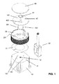
- FIG. 1 schematically shows the housing 10 of an electric motor, in a view obliquely on the rear bearing plate 11.
- a rotary encoder 12 is preferably attached in the form of a magnet, which is connected to the motor shaft rotates and generates in this way rotational signals in the form of a rotating magnetic field.
- This magnet may be, for example, a button magnet 12 attached to the front end of the motor shaft.
- the magnet may be located within the motor housing 10 and then obscured by the end shield 11 or, as in FIG FIG. 1 represented, freely in a corresponding opening of the bearing plate 11 lie.
- reference holes 131, 132 are preferably already introduced during the manufacture of the engine. But you can also be introduced after the completion of the engine, since the end plate 11 to this Purpose does not necessarily need to be removed.
- the reference bores 131, 132 can be arranged with relatively little manufacturing effort with high precision with respect to the motor shaft and its bearing seat and thus also with respect to the encoder magnet 12.
- FIG. 1 further shows a conventional housing 20 in which a support plate or circuit board 40 (circuit board) is located, on which a magnetic sensor (or sensor IC as explained above) 41 is mounted and on the possibly electronic circuits (not shown) for Example for processing sensor signals or for driving the motor can be applied.
- a schematically indicated cable connection 22 serves for example for the transmission of sensor or control signals, for the power supply of the circuits or for other purposes.
- the housing 20 is usually attached via an intermediate ring 21 on the bearing plate 11, for example by means of screws (not shown).
- FIG. 1 further shows a first and a second carrier pin (threaded or dowel pin) 331, 332, which are each fixed with its first end in the first and second reference bore 131, 132 in the bearing plate 11. This can be realized by screwing, soldering, gluing or by insertion with press fit, etc.
- a first bore 231 and a second bore (not shown) through which the first and second support pins 331, 332 respectively extend in the assembled state.
- a third and a fourth reference hole 431, 432 is inserted into the circuit board 40 located in the housing 20, in which in the assembled state respectively the second end of the first and the second carrier pin 331, 332 is fixed as explained above.
- the sensor 41 (or sensor IC) which serves to detect the magnetic field generated by the encoder magnet 12 (here button magnet) mounted on the motor shaft.
- the magnetic field sensor 41 may, for example, be a known Hall sensor and is preferably provided for surface mounting (SMT - Surface Mounted Technology), in particular by soldering. Such sensors can be realized in particular in the form of the aforementioned monolithic magnetic sensor ICs. The terms “sensor” and “sensor IC” can therefore be used interchangeably.
- the sensor 41 is preferably mounted on the underside of the circuit board 40 facing the rotary encoder magnet 12 in order to better detect the magnetic field of the magnet 12. In the presentation of the FIG. 1 For reasons of illustration, the sensor 41 is located on top of the circuit board 40.
- the housing 20 is finally closed with a lid 50.
- the third and the fourth reference bore 431, 432 and the attachment points for the sensor 41 relative to each other with relatively little manufacturing effort with high precision on the circuit board 40 are arranged so that thereby the sensor (or sensor IC) 41st (Which is aligned with respect to the third and fourth reference bore) is positioned correspondingly precisely with respect to the rotary encoder magnet 12.
- the precision of the positioning of the sensor 41 relative to the encoder magnet 12 essentially depends only on the accuracy with which the first and the second reference hole 131, 132 is introduced into the bearing plate 11, as well as the accuracy with which the Sensor 41 is positioned in relation to the third and the fourth reference bore 431, 432.
- the actual position of the sensor 41 on the circuit board 40 is chosen so that it can reliably detect the magnetic field generated by the encoder magnet 12 for detecting its rotational movements. Such a position can be offset exactly in the axial extension of the motor axis or in a plane perpendicular thereto (as in FIG. 1 shown) on the circuit board 40 are located.
- the positioning principle according to the invention is basically also applicable when using an optical or other rotary encoder and a corresponding optical or other sensor.
Landscapes
- Engineering & Computer Science (AREA)
- Microelectronics & Electronic Packaging (AREA)
- Power Engineering (AREA)
- Control Of Stepping Motors (AREA)
Applications Claiming Priority (1)
| Application Number | Priority Date | Filing Date | Title |
|---|---|---|---|
| DE102014100540.6A DE102014100540A1 (de) | 2014-01-17 | 2014-01-17 | Elektrischer Motor mit Drehstellungssensor |
Publications (3)
| Publication Number | Publication Date |
|---|---|
| EP2897263A2 true EP2897263A2 (fr) | 2015-07-22 |
| EP2897263A3 EP2897263A3 (fr) | 2016-06-01 |
| EP2897263B1 EP2897263B1 (fr) | 2018-11-28 |
Family
ID=52358605
Family Applications (1)
| Application Number | Title | Priority Date | Filing Date |
|---|---|---|---|
| EP15020005.3A Active EP2897263B1 (fr) | 2014-01-17 | 2015-01-17 | Moteur électrique avec capteur de position rotative |
Country Status (2)
| Country | Link |
|---|---|
| EP (1) | EP2897263B1 (fr) |
| DE (1) | DE102014100540A1 (fr) |
Families Citing this family (1)
| Publication number | Priority date | Publication date | Assignee | Title |
|---|---|---|---|---|
| DE102018200472A1 (de) * | 2018-01-12 | 2019-07-18 | Volkswagen Aktiengesellschaft | Verbindungsmodul für einen Elektromotor eines Kraftfahrzeugs bzw. Elektromotor für ein Kraftfahrzeug |
Family Cites Families (3)
| Publication number | Priority date | Publication date | Assignee | Title |
|---|---|---|---|---|
| DE102005040647A1 (de) * | 2005-08-27 | 2007-03-08 | Valeo Systèmes d`Essuyage | Elektromotorischer Hilfsantrieb für Fahrzeuge |
| JP5287787B2 (ja) * | 2010-04-16 | 2013-09-11 | 株式会社デンソー | 電動装置 |
| JP5338804B2 (ja) * | 2010-12-28 | 2013-11-13 | 株式会社デンソー | 駆動装置、および、これを用いた電動パワーステアリング装置 |
-
2014
- 2014-01-17 DE DE102014100540.6A patent/DE102014100540A1/de active Pending
-
2015
- 2015-01-17 EP EP15020005.3A patent/EP2897263B1/fr active Active
Non-Patent Citations (1)
| Title |
|---|
| None |
Also Published As
| Publication number | Publication date |
|---|---|
| EP2897263A3 (fr) | 2016-06-01 |
| EP2897263B1 (fr) | 2018-11-28 |
| DE102014100540A1 (de) | 2015-07-23 |
Similar Documents
| Publication | Publication Date | Title |
|---|---|---|
| DE3931257C2 (fr) | ||
| EP2022303B1 (fr) | Dispositif d'alimentation pour des machines d'équipement de cartes de circuits imprimés | |
| EP1908162B1 (fr) | Moteur electrique sans balai | |
| EP3779367B1 (fr) | Dispositif de mesure de la position angulaire d'un arbre | |
| DE3935261A1 (de) | Mehrfachumdrehungswellen-positionssensor mit spielkompensation | |
| DE2800886A1 (de) | Gleichstrommotor | |
| DE102008042912A1 (de) | Sensoreinrichtung zum Erfassen der Drehlage eines rotierenden Bauteils | |
| DE102019007667A1 (de) | Abtasteinheit für eine winkelmesseinrichtung | |
| DE102004059181A1 (de) | Maschine mit integriertem Drehgeber | |
| DE102008013377A1 (de) | Winkelmesssystem und Verfahren zur Herstellung eines Winkelmesssystems | |
| EP3583681B1 (fr) | Machine électrique | |
| WO2009077456A2 (fr) | Micromoteur électrique à bobine intégrée | |
| EP2897263B1 (fr) | Moteur électrique avec capteur de position rotative | |
| EP3683552B1 (fr) | Unité de balayage pour un dispositif de mesure d'angle | |
| DE102025126641A1 (de) | Sensoranordnung sowie elektronisches Bremspedal für ein Brake-by-Wire-System | |
| DE102004056990B4 (de) | Elektrische Maschine, insbesondere bürstenloser Gleichstrommotor, und Verfahren zum Justieren einer Sensoreinheit in einer elektrischen Maschine | |
| DE102015201160B4 (de) | Bürstenloser Gleichstrommotor | |
| DE102008063772A1 (de) | Sensormodul für Drehwinkelsensor | |
| DE102019109734A1 (de) | Lagervorrichtung | |
| DE102006023844B4 (de) | Potentiometer | |
| DE102011054105A1 (de) | Verbindungsleiterplatte | |
| DE102022203538B3 (de) | Verfahren zur Herstellung eines Winkellagegebers, Montagewerkzeug und Winkellagegeber | |
| DE102005050016A1 (de) | Multiturn-Drehgeber | |
| DE102020210407A1 (de) | Rotationsmaschine mit Positionssensor | |
| DE102006032144A1 (de) | Anordnung zur Erfassung der Rotorstellung in einem Elektromotor |
Legal Events
| Date | Code | Title | Description |
|---|---|---|---|
| PUAI | Public reference made under article 153(3) epc to a published international application that has entered the european phase |
Free format text: ORIGINAL CODE: 0009012 |
|
| 17P | Request for examination filed |
Effective date: 20150117 |
|
| AK | Designated contracting states |
Kind code of ref document: A2 Designated state(s): AL AT BE BG CH CY CZ DE DK EE ES FI FR GB GR HR HU IE IS IT LI LT LU LV MC MK MT NL NO PL PT RO RS SE SI SK SM TR |
|
| AX | Request for extension of the european patent |
Extension state: BA ME |
|
| PUAL | Search report despatched |
Free format text: ORIGINAL CODE: 0009013 |
|
| RIC1 | Information provided on ipc code assigned before grant |
Ipc: H02K 11/00 20160101AFI20160412BHEP |
|
| AK | Designated contracting states |
Kind code of ref document: A3 Designated state(s): AL AT BE BG CH CY CZ DE DK EE ES FI FR GB GR HR HU IE IS IT LI LT LU LV MC MK MT NL NO PL PT RO RS SE SI SK SM TR |
|
| AX | Request for extension of the european patent |
Extension state: BA ME |
|
| RIC1 | Information provided on ipc code assigned before grant |
Ipc: H02K 11/00 20160101AFI20160426BHEP |
|
| STAA | Information on the status of an ep patent application or granted ep patent |
Free format text: STATUS: REQUEST FOR EXAMINATION WAS MADE |
|
| 17P | Request for examination filed |
Effective date: 20161124 |
|
| RBV | Designated contracting states (corrected) |
Designated state(s): AL AT BE BG CH CY CZ DE DK EE ES FI FR GB GR HR HU IE IS IT LI LT LU LV MC MK MT NL NO PL PT RO RS SE SI SK SM TR |
|
| GRAP | Despatch of communication of intention to grant a patent |
Free format text: ORIGINAL CODE: EPIDOSNIGR1 |
|
| STAA | Information on the status of an ep patent application or granted ep patent |
Free format text: STATUS: GRANT OF PATENT IS INTENDED |
|
| INTG | Intention to grant announced |
Effective date: 20180620 |
|
| GRAS | Grant fee paid |
Free format text: ORIGINAL CODE: EPIDOSNIGR3 |
|
| GRAA | (expected) grant |
Free format text: ORIGINAL CODE: 0009210 |
|
| STAA | Information on the status of an ep patent application or granted ep patent |
Free format text: STATUS: THE PATENT HAS BEEN GRANTED |
|
| AK | Designated contracting states |
Kind code of ref document: B1 Designated state(s): AL AT BE BG CH CY CZ DE DK EE ES FI FR GB GR HR HU IE IS IT LI LT LU LV MC MK MT NL NO PL PT RO RS SE SI SK SM TR |
|
| REG | Reference to a national code |
Ref country code: CH Ref legal event code: EP |
|
| REG | Reference to a national code |
Ref country code: AT Ref legal event code: REF Ref document number: 1071396 Country of ref document: AT Kind code of ref document: T Effective date: 20181215 |
|
| REG | Reference to a national code |
Ref country code: DE Ref legal event code: R096 Ref document number: 502015006964 Country of ref document: DE |
|
| REG | Reference to a national code |
Ref country code: IE Ref legal event code: FG4D Free format text: LANGUAGE OF EP DOCUMENT: GERMAN |
|
| REG | Reference to a national code |
Ref country code: NL Ref legal event code: MP Effective date: 20181128 |
|
| REG | Reference to a national code |
Ref country code: LT Ref legal event code: MG4D |
|
| PG25 | Lapsed in a contracting state [announced via postgrant information from national office to epo] |
Ref country code: IS Free format text: LAPSE BECAUSE OF FAILURE TO SUBMIT A TRANSLATION OF THE DESCRIPTION OR TO PAY THE FEE WITHIN THE PRESCRIBED TIME-LIMIT Effective date: 20190328 Ref country code: LT Free format text: LAPSE BECAUSE OF FAILURE TO SUBMIT A TRANSLATION OF THE DESCRIPTION OR TO PAY THE FEE WITHIN THE PRESCRIBED TIME-LIMIT Effective date: 20181128 Ref country code: ES Free format text: LAPSE BECAUSE OF FAILURE TO SUBMIT A TRANSLATION OF THE DESCRIPTION OR TO PAY THE FEE WITHIN THE PRESCRIBED TIME-LIMIT Effective date: 20181128 Ref country code: NO Free format text: LAPSE BECAUSE OF FAILURE TO SUBMIT A TRANSLATION OF THE DESCRIPTION OR TO PAY THE FEE WITHIN THE PRESCRIBED TIME-LIMIT Effective date: 20190228 Ref country code: BG Free format text: LAPSE BECAUSE OF FAILURE TO SUBMIT A TRANSLATION OF THE DESCRIPTION OR TO PAY THE FEE WITHIN THE PRESCRIBED TIME-LIMIT Effective date: 20190228 Ref country code: HR Free format text: LAPSE BECAUSE OF FAILURE TO SUBMIT A TRANSLATION OF THE DESCRIPTION OR TO PAY THE FEE WITHIN THE PRESCRIBED TIME-LIMIT Effective date: 20181128 Ref country code: LV Free format text: LAPSE BECAUSE OF FAILURE TO SUBMIT A TRANSLATION OF THE DESCRIPTION OR TO PAY THE FEE WITHIN THE PRESCRIBED TIME-LIMIT Effective date: 20181128 Ref country code: FI Free format text: LAPSE BECAUSE OF FAILURE TO SUBMIT A TRANSLATION OF THE DESCRIPTION OR TO PAY THE FEE WITHIN THE PRESCRIBED TIME-LIMIT Effective date: 20181128 |
|
| PG25 | Lapsed in a contracting state [announced via postgrant information from national office to epo] |
Ref country code: SE Free format text: LAPSE BECAUSE OF FAILURE TO SUBMIT A TRANSLATION OF THE DESCRIPTION OR TO PAY THE FEE WITHIN THE PRESCRIBED TIME-LIMIT Effective date: 20181128 Ref country code: AL Free format text: LAPSE BECAUSE OF FAILURE TO SUBMIT A TRANSLATION OF THE DESCRIPTION OR TO PAY THE FEE WITHIN THE PRESCRIBED TIME-LIMIT Effective date: 20181128 Ref country code: RS Free format text: LAPSE BECAUSE OF FAILURE TO SUBMIT A TRANSLATION OF THE DESCRIPTION OR TO PAY THE FEE WITHIN THE PRESCRIBED TIME-LIMIT Effective date: 20181128 Ref country code: GR Free format text: LAPSE BECAUSE OF FAILURE TO SUBMIT A TRANSLATION OF THE DESCRIPTION OR TO PAY THE FEE WITHIN THE PRESCRIBED TIME-LIMIT Effective date: 20190301 Ref country code: PT Free format text: LAPSE BECAUSE OF FAILURE TO SUBMIT A TRANSLATION OF THE DESCRIPTION OR TO PAY THE FEE WITHIN THE PRESCRIBED TIME-LIMIT Effective date: 20190328 |
|
| PG25 | Lapsed in a contracting state [announced via postgrant information from national office to epo] |
Ref country code: NL Free format text: LAPSE BECAUSE OF FAILURE TO SUBMIT A TRANSLATION OF THE DESCRIPTION OR TO PAY THE FEE WITHIN THE PRESCRIBED TIME-LIMIT Effective date: 20181128 |
|
| PG25 | Lapsed in a contracting state [announced via postgrant information from national office to epo] |
Ref country code: DK Free format text: LAPSE BECAUSE OF FAILURE TO SUBMIT A TRANSLATION OF THE DESCRIPTION OR TO PAY THE FEE WITHIN THE PRESCRIBED TIME-LIMIT Effective date: 20181128 Ref country code: IT Free format text: LAPSE BECAUSE OF FAILURE TO SUBMIT A TRANSLATION OF THE DESCRIPTION OR TO PAY THE FEE WITHIN THE PRESCRIBED TIME-LIMIT Effective date: 20181128 Ref country code: PL Free format text: LAPSE BECAUSE OF FAILURE TO SUBMIT A TRANSLATION OF THE DESCRIPTION OR TO PAY THE FEE WITHIN THE PRESCRIBED TIME-LIMIT Effective date: 20181128 Ref country code: CZ Free format text: LAPSE BECAUSE OF FAILURE TO SUBMIT A TRANSLATION OF THE DESCRIPTION OR TO PAY THE FEE WITHIN THE PRESCRIBED TIME-LIMIT Effective date: 20181128 |
|
| REG | Reference to a national code |
Ref country code: DE Ref legal event code: R097 Ref document number: 502015006964 Country of ref document: DE |
|
| PG25 | Lapsed in a contracting state [announced via postgrant information from national office to epo] |
Ref country code: SM Free format text: LAPSE BECAUSE OF FAILURE TO SUBMIT A TRANSLATION OF THE DESCRIPTION OR TO PAY THE FEE WITHIN THE PRESCRIBED TIME-LIMIT Effective date: 20181128 Ref country code: SK Free format text: LAPSE BECAUSE OF FAILURE TO SUBMIT A TRANSLATION OF THE DESCRIPTION OR TO PAY THE FEE WITHIN THE PRESCRIBED TIME-LIMIT Effective date: 20181128 Ref country code: RO Free format text: LAPSE BECAUSE OF FAILURE TO SUBMIT A TRANSLATION OF THE DESCRIPTION OR TO PAY THE FEE WITHIN THE PRESCRIBED TIME-LIMIT Effective date: 20181128 Ref country code: MC Free format text: LAPSE BECAUSE OF FAILURE TO SUBMIT A TRANSLATION OF THE DESCRIPTION OR TO PAY THE FEE WITHIN THE PRESCRIBED TIME-LIMIT Effective date: 20181128 Ref country code: EE Free format text: LAPSE BECAUSE OF FAILURE TO SUBMIT A TRANSLATION OF THE DESCRIPTION OR TO PAY THE FEE WITHIN THE PRESCRIBED TIME-LIMIT Effective date: 20181128 |
|
| PG25 | Lapsed in a contracting state [announced via postgrant information from national office to epo] |
Ref country code: LU Free format text: LAPSE BECAUSE OF NON-PAYMENT OF DUE FEES Effective date: 20190117 |
|
| PLBE | No opposition filed within time limit |
Free format text: ORIGINAL CODE: 0009261 |
|
| STAA | Information on the status of an ep patent application or granted ep patent |
Free format text: STATUS: NO OPPOSITION FILED WITHIN TIME LIMIT |
|
| PG25 | Lapsed in a contracting state [announced via postgrant information from national office to epo] |
Ref country code: SI Free format text: LAPSE BECAUSE OF FAILURE TO SUBMIT A TRANSLATION OF THE DESCRIPTION OR TO PAY THE FEE WITHIN THE PRESCRIBED TIME-LIMIT Effective date: 20181128 |
|
| 26N | No opposition filed |
Effective date: 20190829 |
|
| PG25 | Lapsed in a contracting state [announced via postgrant information from national office to epo] |
Ref country code: TR Free format text: LAPSE BECAUSE OF FAILURE TO SUBMIT A TRANSLATION OF THE DESCRIPTION OR TO PAY THE FEE WITHIN THE PRESCRIBED TIME-LIMIT Effective date: 20181128 |
|
| REG | Reference to a national code |
Ref country code: DE Ref legal event code: R082 Ref document number: 502015006964 Country of ref document: DE Representative=s name: CANZLER & BERGMEIER PATENTANWAELTE PARTNERSCHA, DE Ref country code: DE Ref legal event code: R082 Ref document number: 502015006964 Country of ref document: DE Representative=s name: HEUN, THOMAS, DIPL.-ING.UNIV., DE Ref country code: DE Ref legal event code: R082 Ref document number: 502015006964 Country of ref document: DE Representative=s name: PATENTANWAELTE CANZLER & BERGMEIER PARTNERSCHA, DE |
|
| PG25 | Lapsed in a contracting state [announced via postgrant information from national office to epo] |
Ref country code: MT Free format text: LAPSE BECAUSE OF FAILURE TO SUBMIT A TRANSLATION OF THE DESCRIPTION OR TO PAY THE FEE WITHIN THE PRESCRIBED TIME-LIMIT Effective date: 20181128 |
|
| REG | Reference to a national code |
Ref country code: DE Ref legal event code: R082 Ref document number: 502015006964 Country of ref document: DE Representative=s name: CANZLER & BERGMEIER PATENTANWAELTE PARTNERSCHA, DE Ref country code: DE Ref legal event code: R082 Ref document number: 502015006964 Country of ref document: DE Representative=s name: PATENTANWAELTE CANZLER & BERGMEIER PARTNERSCHA, DE Ref country code: DE Ref legal event code: R081 Ref document number: 502015006964 Country of ref document: DE Owner name: MAXIM INTEGRATED PRODUCTS, INC., SAN JOSE, US Free format text: FORMER OWNER: TRINAMIC MOTION CONTROL GMBH & CO. KG, 22769 HAMBURG, DE |
|
| REG | Reference to a national code |
Ref country code: CH Ref legal event code: NV Representative=s name: SPIERENBURG AND PARTNER AG, PATENT- UND MARKEN, CH Ref country code: CH Ref legal event code: PUE Owner name: MAXIM INTEGRATED PRODUCTS, INC., US Free format text: FORMER OWNER: TRINAMIC MOTION CONTROL GMBH AND CO. KG, DE |
|
| REG | Reference to a national code |
Ref country code: GB Ref legal event code: 732E Free format text: REGISTERED BETWEEN 20201015 AND 20201021 |
|
| REG | Reference to a national code |
Ref country code: AT Ref legal event code: PC Ref document number: 1071396 Country of ref document: AT Kind code of ref document: T Owner name: MAXIM INTEGRATED PRODUCTS, INC., US Effective date: 20210121 |
|
| PG25 | Lapsed in a contracting state [announced via postgrant information from national office to epo] |
Ref country code: CY Free format text: LAPSE BECAUSE OF FAILURE TO SUBMIT A TRANSLATION OF THE DESCRIPTION OR TO PAY THE FEE WITHIN THE PRESCRIBED TIME-LIMIT Effective date: 20181128 |
|
| PG25 | Lapsed in a contracting state [announced via postgrant information from national office to epo] |
Ref country code: HU Free format text: LAPSE BECAUSE OF FAILURE TO SUBMIT A TRANSLATION OF THE DESCRIPTION OR TO PAY THE FEE WITHIN THE PRESCRIBED TIME-LIMIT; INVALID AB INITIO Effective date: 20150117 |
|
| REG | Reference to a national code |
Ref country code: BE Ref legal event code: PD Owner name: MAXIM INTEGRATED PRODUCTS, INC.; US Free format text: DETAILS ASSIGNMENT: CHANGE OF OWNER(S), ASSIGNMENT; FORMER OWNER NAME: TRINAMIC MOTION CONTROL GMBH & CO. KG Effective date: 20201102 |
|
| PGFP | Annual fee paid to national office [announced via postgrant information from national office to epo] |
Ref country code: IE Payment date: 20220127 Year of fee payment: 8 Ref country code: GB Payment date: 20220127 Year of fee payment: 8 Ref country code: CH Payment date: 20220202 Year of fee payment: 8 Ref country code: AT Payment date: 20220103 Year of fee payment: 8 |
|
| PGFP | Annual fee paid to national office [announced via postgrant information from national office to epo] |
Ref country code: FR Payment date: 20220125 Year of fee payment: 8 Ref country code: BE Payment date: 20220127 Year of fee payment: 8 |
|
| PG25 | Lapsed in a contracting state [announced via postgrant information from national office to epo] |
Ref country code: MK Free format text: LAPSE BECAUSE OF FAILURE TO SUBMIT A TRANSLATION OF THE DESCRIPTION OR TO PAY THE FEE WITHIN THE PRESCRIBED TIME-LIMIT Effective date: 20181128 |
|
| REG | Reference to a national code |
Ref country code: CH Ref legal event code: PL |
|
| REG | Reference to a national code |
Ref country code: AT Ref legal event code: MM01 Ref document number: 1071396 Country of ref document: AT Kind code of ref document: T Effective date: 20230117 |
|
| GBPC | Gb: european patent ceased through non-payment of renewal fee |
Effective date: 20230117 |
|
| REG | Reference to a national code |
Ref country code: BE Ref legal event code: MM Effective date: 20230131 |
|
| PG25 | Lapsed in a contracting state [announced via postgrant information from national office to epo] |
Ref country code: LI Free format text: LAPSE BECAUSE OF NON-PAYMENT OF DUE FEES Effective date: 20230131 Ref country code: GB Free format text: LAPSE BECAUSE OF NON-PAYMENT OF DUE FEES Effective date: 20230117 Ref country code: CH Free format text: LAPSE BECAUSE OF NON-PAYMENT OF DUE FEES Effective date: 20230131 Ref country code: AT Free format text: LAPSE BECAUSE OF NON-PAYMENT OF DUE FEES Effective date: 20230117 |
|
| PG25 | Lapsed in a contracting state [announced via postgrant information from national office to epo] |
Ref country code: FR Free format text: LAPSE BECAUSE OF NON-PAYMENT OF DUE FEES Effective date: 20230131 Ref country code: BE Free format text: LAPSE BECAUSE OF NON-PAYMENT OF DUE FEES Effective date: 20230131 |
|
| PG25 | Lapsed in a contracting state [announced via postgrant information from national office to epo] |
Ref country code: IE Free format text: LAPSE BECAUSE OF NON-PAYMENT OF DUE FEES Effective date: 20230117 |
|
| PGFP | Annual fee paid to national office [announced via postgrant information from national office to epo] |
Ref country code: DE Payment date: 20251217 Year of fee payment: 12 |