EP2896970A1 - Method of kinematic ranging - Google Patents
Method of kinematic ranging Download PDFInfo
- Publication number
- EP2896970A1 EP2896970A1 EP14000178.5A EP14000178A EP2896970A1 EP 2896970 A1 EP2896970 A1 EP 2896970A1 EP 14000178 A EP14000178 A EP 14000178A EP 2896970 A1 EP2896970 A1 EP 2896970A1
- Authority
- EP
- European Patent Office
- Prior art keywords
- jammer
- airborne
- radar
- components
- straight line
- Prior art date
- Legal status (The legal status is an assumption and is not a legal conclusion. Google has not performed a legal analysis and makes no representation as to the accuracy of the status listed.)
- Granted
Links
Images


Classifications
-
- G—PHYSICS
- G01—MEASURING; TESTING
- G01S—RADIO DIRECTION-FINDING; RADIO NAVIGATION; DETERMINING DISTANCE OR VELOCITY BY USE OF RADIO WAVES; LOCATING OR PRESENCE-DETECTING BY USE OF THE REFLECTION OR RERADIATION OF RADIO WAVES; ANALOGOUS ARRANGEMENTS USING OTHER WAVES
- G01S7/00—Details of systems according to groups G01S13/00, G01S15/00, G01S17/00
- G01S7/02—Details of systems according to groups G01S13/00, G01S15/00, G01S17/00 of systems according to group G01S13/00
- G01S7/36—Means for anti-jamming, e.g. ECCM, i.e. electronic counter-counter measures
-
- G—PHYSICS
- G01—MEASURING; TESTING
- G01S—RADIO DIRECTION-FINDING; RADIO NAVIGATION; DETERMINING DISTANCE OR VELOCITY BY USE OF RADIO WAVES; LOCATING OR PRESENCE-DETECTING BY USE OF THE REFLECTION OR RERADIATION OF RADIO WAVES; ANALOGOUS ARRANGEMENTS USING OTHER WAVES
- G01S11/00—Systems for determining distance or velocity not using reflection or reradiation
- G01S11/02—Systems for determining distance or velocity not using reflection or reradiation using radio waves
- G01S11/04—Systems for determining distance or velocity not using reflection or reradiation using radio waves using angle measurements
-
- G—PHYSICS
- G01—MEASURING; TESTING
- G01S—RADIO DIRECTION-FINDING; RADIO NAVIGATION; DETERMINING DISTANCE OR VELOCITY BY USE OF RADIO WAVES; LOCATING OR PRESENCE-DETECTING BY USE OF THE REFLECTION OR RERADIATION OF RADIO WAVES; ANALOGOUS ARRANGEMENTS USING OTHER WAVES
- G01S7/00—Details of systems according to groups G01S13/00, G01S15/00, G01S17/00
- G01S7/02—Details of systems according to groups G01S13/00, G01S15/00, G01S17/00 of systems according to group G01S13/00
- G01S7/021—Auxiliary means for detecting or identifying radar signals or the like, e.g. radar jamming signals
-
- G—PHYSICS
- G01—MEASURING; TESTING
- G01S—RADIO DIRECTION-FINDING; RADIO NAVIGATION; DETERMINING DISTANCE OR VELOCITY BY USE OF RADIO WAVES; LOCATING OR PRESENCE-DETECTING BY USE OF THE REFLECTION OR RERADIATION OF RADIO WAVES; ANALOGOUS ARRANGEMENTS USING OTHER WAVES
- G01S7/00—Details of systems according to groups G01S13/00, G01S15/00, G01S17/00
- G01S7/02—Details of systems according to groups G01S13/00, G01S15/00, G01S17/00 of systems according to group G01S13/00
- G01S7/38—Jamming means, e.g. producing false echoes
Definitions
- the invention relates to kinematic ranging techniques.
- Kinematic ranging per se is a known electronic counter-counter-measure technique, in which the range of a moving airborne jammer may be estimated by use of a radar unit without the need for the unit to actively interrogate the jammer, i.e. the radar unit may work in a passive mode to detect and process the jammer signals.
- the radar unit is an airborne detecting radar unit.
- Kinematic ranging is described for example in " Kinematic Ranging for IRST", SPIE Vol 1950, Acquisition, Tracking and Pointing VII (1993 ).
- ⁇ is the angle in the azimuthal plane between the straight line joining the position of the airborne detector radar at time t 1 and the position of the jammer at t 2 and the straight line corresponding to the displacement of the airborne detector radar during the interval ⁇ t.
- the range R of the jammer from the second position 16 of the airborne detecting radar may be therefore be calculated by measuring the bearings ⁇ 1 , ⁇ 2 in azimuth of the jammer at the times t 1 , t 2 with respect to the airborne detecting radar unit, the rate of change d ⁇ /dt of the bearing in azimuth of the jammer with respect to the position 14, the components ⁇ x, ⁇ y of the displacement 22 corresponding to the manoevre 20 of the airborne detecting radar, and the time interval ⁇ t.
- a disadvantage of the known method of kinematic ranging is that when the airborne detecting radar unit carries out a general manoevre 20, corresponding to a general displacement such as 22, the final result for the range R typically involves a significant level of uncertainty as a result of measurement errors associated with the values of ⁇ 1 , ⁇ 2 , d ⁇ /dt, ⁇ t, ⁇ x and ⁇ y.
- the present invention provides a method of kinematic ranging comprising the steps of:
- the invention provides the advantage that the range R may be measured with a desired relative range accuracy by causing the airborne radar detector to carry out the manoevre d having the calculated displacement components ⁇ x, ⁇ y in the horizontal plane.
- the method further comprises the steps of
- the method may be applied to the simultaneous determination of the range of two jammers, in which case the method preferably further includes the steps of:
- ⁇ R 2 ⁇ R ⁇ ⁇ ⁇ ⁇ 2 ⁇ ⁇ ⁇ ⁇ 2 + ⁇ R ⁇ ⁇ ⁇ a 2 ⁇ ⁇ ⁇ ⁇ ⁇ a 2 + ⁇ R ⁇ d 2 ⁇ ⁇ d 2
- ⁇ 2 ⁇ , ⁇ 2 ⁇ , and ⁇ 2 d are the variances in the angles ⁇ , ⁇ and in the displacement d respectively.
- the values ⁇ 1 , d ⁇ /dt are measured when the airborne detector radar is at postion 14, as described above with reference to Figure 1 .
- the time ⁇ t taken for the airborne detector radar to carry out the manoevre 20 in order to cover the displacement d is d/v + dt where v is the velocity of the radar detector and dt is a tolerance value.
- Figure 3 shows the displacement 32 of length d, the angle ⁇ being 90° in this case.
- the jammer moves from a position 20 to a position 22 along a trajectory 28 in a time interval ⁇ t, during which the airborne detector radar moves from a position 24 to a position 26, these positions defining the displacement d.
- Figure 4 illustrates how the method may be applied to find the range of multiple jammers by increasing the number of manoevres carried out by a detecting airborne radar.
- n jammers are located and assessed at time t 1 and have bearings in azimuth of ⁇ 11 .... ⁇ n1 .
- the measured bearings in azimuth of the jammers are ⁇ 12 .... ⁇ n2 .
- R n sin ⁇ ⁇ ⁇ n ⁇ ⁇ ⁇ x 2 + ⁇ ⁇ y 2 sin ⁇ ⁇ ⁇ n .
- the value ⁇ 1 is approximately 60° which leads to acceptable results, however ⁇ n may become close to zero, so that the relative range accuracy for the measurement of R n approaches a pole.
- the manoevre of the airborne detector radar may be carried out so that the displacement ⁇ x is negative, as shown in Figure 5 ; in this case a displacement 52 between positions 44 and 46 is achieved by a manoevre 50.
- ⁇ n is approximately 90°, so that the error in the range R is minimised, and ⁇ 1 is approximately 60°, which results in the accuracy of the measurement of R 1 also being acceptable.
- the manoevre is optimised for jammer 1, the angle velocity d ⁇ /dt of jammer 1 increases ⁇ 1 without lowering ⁇ n ; this is because both jammers have the same direction of angle velocity d ⁇ /dt.
Landscapes
- Engineering & Computer Science (AREA)
- Radar, Positioning & Navigation (AREA)
- Remote Sensing (AREA)
- Physics & Mathematics (AREA)
- General Physics & Mathematics (AREA)
- Computer Networks & Wireless Communication (AREA)
- Radar Systems Or Details Thereof (AREA)
Abstract
Description
- The invention relates to kinematic ranging techniques.
- Kinematic ranging per se is a known electronic counter-counter-measure technique, in which the range of a moving airborne jammer may be estimated by use of a radar unit without the need for the unit to actively interrogate the jammer, i.e. the radar unit may work in a passive mode to detect and process the jammer signals. In the specific examples of the invention described below, the radar unit is an airborne detecting radar unit. Kinematic ranging is described for example in "Kinematic Ranging for IRST", SPIE Vol 1950, Acquisition, Tracking and Pointing VII (1993).
- Referring to
Figure 1 , in a known kinematic ranging technique, an airborne jammer moves along a trajectory 18 from afirst position 10 to asecond position 12 in a time interval Δt = t2 - t1, during which an airborne detecting radar unit carries out a manoevre along apath 20 from aposition 14 to aposition 16, corresponding to adisplacement 22 defined by displacement components Δx, Δy in the x and y directions respectively. The change Δα in azimuth bearing angle of the jammer with respect to the airborne detecting radar unit between the times t1 and t2 is given by
where α1 and α2 are the bearings in azimuth of the jammer at times t1 and t2 with respect topositions line connecting positions displacement 22 is given by
- Δβ is the angle in the azimuthal plane between the straight line joining the position of the airborne detector radar at time t1 and the position of the jammer at t2 and the straight line corresponding to the displacement of the airborne detector radar during the interval Δt. Using the sine rule, the range R of the jammer from the airborne detecting radar at time t2 is given by

- The range R of the jammer from the
second position 16 of the airborne detecting radar may be therefore be calculated by measuring the bearings α1, α2 in azimuth of the jammer at the times t1, t2 with respect to the airborne detecting radar unit, the rate of change dα/dt of the bearing in azimuth of the jammer with respect to theposition 14, the components Δx, Δy of thedisplacement 22 corresponding to themanoevre 20 of the airborne detecting radar, and the time interval Δt. - A disadvantage of the known method of kinematic ranging is that when the airborne detecting radar unit carries out a
general manoevre 20, corresponding to a general displacement such as 22, the final result for the range R typically involves a significant level of uncertainty as a result of measurement errors associated with the values of α1, α2, dα/dt, Δt, Δx and Δy. - The present invention provides a method of kinematic ranging comprising the steps of:
- (i) measuring the bearing α1 in azimuth of a jammer at a time t1 with respect to a first position using an airborne radar detector located at the first position;
- (ii) measuring the rate of change dα/dt of the bearing in azimuth of the jammer with respect to the first position using the airborne radar detector located at the first postion;
- (iii) causing the airborne radar detector to carry out a manoevre such that it is displaced to a second position by a horizontal displacement d having orthogonal components Δx, Δy in a time Δt = t2 - t1 and measuring the bearing α2 in azimuth of the jammer at time t2 with respect to the second position using the airborne radar detector located at the second position, where

- (iv) calculating the difference Δα in the bearing in azimuth of the jammer between the second and first positions;
- (a) choosing a desired relative range accuracy σR/R for the method;
- (b) obtaining an estimated range Rest of the jammer from the second position at time t2;
- (c) finding d on the basis of the relative range accuracy, the estimated range Rest, the variance σΔα 2 in Δα and the variance σd 2 in d according to

- (d) calculating the components Δx, Δy of the displacement d according to


and also characterised in that the range R of the jammer from the second position is calculated according to
- The invention provides the advantage that the range R may be measured with a desired relative range accuracy by causing the airborne radar detector to carry out the manoevre d having the calculated displacement components Δx, Δy in the horizontal plane.
- In order to provide the possibility of a further increase in the accuracy of the determined range R, preferably the method further comprises the steps of
- (i) evaluating the angle Δβ1 between the straight line joining the first position of the airborne detector radar and the position of the jammer at time t2, and the straight line defined by the components Δx, Δy;
- (ii) evaluating the angle Δβ2 between the straight line joining the first position of the airborne detector radar and the position of the jammer at time t2, and the straight line defined by the components -Δx, Δy;
- (iii) if |Δβ1 -π/2|≤ |Δβ2 -π/2| then choosing the manoevre of the airborne detector radar such that its displacement has components Δx, Δy and if |Δβ1 -π/2| > |Δβ2 -π/2| then choosing the manoevre of the airborne detector radar such that its displacement has components -Δx, Δy.
- In some embodiments, the method may be applied to the simultaneous determination of the range of two jammers, in which case the method preferably further includes the steps of:
- (i) evaluating the angle Δβ11 between the straight line joining the first position of the airborne detector radar and the position of the first jammer at time t2, and the straight line defined by the components Δx, Δy;
- (ii) evaluating the angle Δβ12 between the straight line joining the first position of the airborne detector radar and the position of the second jammer at time t2, and the straight line defined by the components Δx, Δy;
- (iii) evaluating the angle Δβ21 between the straight line joining the first position of the airborne detector radar and the position of the first jammer at time t2, and the straight line defined by the components -Δx, Δy;
- (iv) evaluating the angle Δβ22 between the straight line joining the first position of the airborne detector radar and the position of the second jammer at time t2, and the straight line defined by the components -Δx, Δy;
- (v) if |Δβ11 + Δβ12 - π| ≤ |Δβ21 + Δβ22 - π| then choosing the manoevre of the airborne detector radar such that its displacement has components Δx, Δy and if |Δβ11 + Δβ12-π| > |Δβ21 + Δβ22 -π| then choosing the manoevre of the airborne detector radar such that its displacement has components -Δx, Δy.
- This ensure the greatest overall accuracy in the determined ranges of the two jammers.
- Embodiments of the invention are described below by way of example only, and with reference to the accompanying drawings in which:
- Figure 2
- shows the relationship between the range R of a jammer and the displacement d of a manoevre of an airborne radar detector executed in a method of the invention in the case of a relative range accuracy of less than 20%;
- Figure 3
- illustrates the measurement of the range R of a jammer with minimum uncertainty;
- Figure 4
- illustrates a non-optimised manoevre of an airborne detector radar for estimating the range of multiple jammers; and
- Figure 5
- illustrates an alternative manoevre of an airborne detector radar for estimating the ranges of multiple jammers with improved accuracy.
- Using Gauss' law in conjunction with Equation 2, the variance in the range R of the jammer is given by

where σ2 Δβ, σ2 Δα, and σ2 d are the variances in the angles Δβ, Δα and in the displacement d respectively. Inserting the derivatives of Equation 2 into Equation 3 gives an expression for the relative range accuracy σR/R:
which is minimised when
and Δα and d are as large as possible. cot2 (Δβ) = 0 if Δβ = π/2; combining this withEquation 1 gives
or equivalently
- For Δβ =π/2, Equations 2 and 3 can be written as

and
-
Figure 2 shows a plane through the function of Equation 4 at the value σR/R = 0.2 assuming accuracies σd, σΔα in the measurement of d and Δα of 700m and 1° respectively. If an initial value of the range R of 70 km is estimated, fromFigure 2 this corresponds to a displacement d of ∼7000m. The values α1, dα/dt are measured when the airborne detector radar is atpostion 14, as described above with reference toFigure 1 . The time Δt taken for the airborne detector radar to carry out themanoevre 20 in order to cover the displacement d is d/v + dt where v is the velocity of the radar detector and dt is a tolerance value.
- Taking d = 7000m , dt =5s and v =250 m/s, and assuming that α1 = -20° and α̇ = 0.2°/s, the components Δx, Δy of the displacement d are


- If the airborne detector radar carries out the
manouvre 20 using these components of the displacement d, then the error in the measurement of the range R has a relative range accuracy of 20% or better.Figure 3 shows thedisplacement 32 of length d, the angle Δβ being 90° in this case. InFigure 3 , the jammer moves from aposition 20 to aposition 22 along atrajectory 28 in a time interval Δt, during which the airborne detector radar moves from aposition 24 to aposition 26, these positions defining the displacement d. -
Figure 4 illustrates how the method may be applied to find the range of multiple jammers by increasing the number of manoevres carried out by a detecting airborne radar. In this case, n jammers are located and assessed at time t1 and have bearings in azimuth of α11....αn1. The airborne detector radar carries out a manoevre on apath 40 frompoint 34 to theend 36 which define adisplacement 42 of length d = (Δx2 + Δy2)1/2. At time t2 at theposition 36, the measured bearings in azimuth of the jammers are α12....αn2. The differences in bearing Δαn and the angle Δβn are

- and the range Rn of the nth jammer is given by

- In
Figure 4 , the value Δβ1 is approximately 60° which leads to acceptable results, however Δβn may become close to zero, so that the relative range accuracy for the measurement of Rn approaches a pole. To avoid this, the manoevre of the airborne detector radar may be carried out so that the displacement Δx is negative, as shown inFigure 5 ; in this case adisplacement 52 betweenpositions manoevre 50. Using thismaneovre 50, Δβn is approximately 90°, so that the error in the range R is minimised, and Δβ1 is approximately 60°, which results in the accuracy of the measurement of R1 also being acceptable. In this example, although the manoevre is optimised forjammer 1, the angle velocity dα/dt ofjammer 1 increases Δβ1 without lowering Δβn; this is because both jammers have the same direction of angle velocity dα/dt.
Claims (3)
- A method of kinematic ranging comprising the steps of:(i) measuring the bearing α1 in azimuth of a jammer at a time t1 with respect to a first postion using an airborne radar detector located at the first position;(ii) measuring the rate of change dα/dt of the bearing in azimuth of the jammer with respect to the first position using the airborne radar detector located at the first position;(iii) causing the airborne radar detector to carry out a manoevre such that it is displaced to a second position by a horizontal displacement d having orthogonal components Δx, Δy in a time Δt = t2 - t1 and measuring the bearing α2 in azimuth of the jammer at time t2 with respect to the second position using the airborne radar detector located at the second position, where
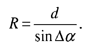
 (iv) calculating the difference Δα in the bearing in azimuth of the jammer between the second and first positions;characterised in that the components Δx, Δy are calculated by the steps of:(a) choosing a desired relative range accuracy σR/R for the method;(b) obtaining an estimated range Rest of the jammer from the second position at time t2;(c) finding d on the basis of the relative range accuracy, the estimated range Rest, the variance σΔα 2 in Δα and the variance αd 2 in d according to
 (d) calculating the components Δx, Δy of the displacement d according toand characterised in that the range R of the jammer from the second position is calculated according to

- A method according to claim 1, further comprising the steps of:(i) evaluating the angle Δβ1 between the straight line joining the first position of the airborne detector radar and the position of the jammer at time t2, and the straight line defined by the components Δx, Δy;(ii) evaluating the angle Δβ2 between the straight line joining the first position of the airborne detector radar and the position of the jammer at time t2, and the straight line defined by the components -Δx, Δy;(iii) if |Δβ1 -π/2| ≤ |Δβ2 -π/2| then choosing the manoevre of the airborne detector radar such that its displacement has components Δx, Δy and if |Δβ1 -π/2| > |Δβ2 -π/2| then choosing the manoevre of the airborne detector radar such that its displacement has components -Δx, Δy.
- A method according to claim 1 wherein the range of a second jammer is also determined, and wherein the method comprises the steps of:(i) evaluating the angle Δβ11 between the straight line joining the first position of the airborne detector radar and the position of the first jammer at time t2, and the straight line defined by the components Δx, Δy;(ii) evaluating the angle Δβ12 between the straight line joining the first position of the airborne detector radar and the position of the second jammer at time t2, and the straight line defined by the components Δx, Δy;(iii) evaluating the angle Δβ21 between the straight line joining the first position of the airborne detector radar and the position of the first jammer at time t2, and the straight line defined by the components -Δx, Δy;(iv) evaluating the angle Δβ22 between the straight line joining the first position of the airborne detector radar and the position of the second jammer at time t2, and the straight line defined by the components -Δx, Δy;(v) if |Δβ11| + Δβ12 - π| ≤ |Δβ21 + Δβ22 - π| then choosing the manoevre of the airborne detector radar such that its displacement has components Δx, Δy and if |Δβ11 + Δβ12 -π| > |Δβ21 + Δβ22 -π| then choosing the manoevre of the airborne detector radar such that its displacement has components -Δx, Δy.
Priority Applications (2)
| Application Number | Priority Date | Filing Date | Title |
|---|---|---|---|
| EP14000178.5A EP2896970B1 (en) | 2014-01-17 | 2014-01-17 | Method of kinematic ranging |
| US14/598,735 US9476967B2 (en) | 2014-01-17 | 2015-01-16 | Method of kinematic ranging |
Applications Claiming Priority (1)
| Application Number | Priority Date | Filing Date | Title |
|---|---|---|---|
| EP14000178.5A EP2896970B1 (en) | 2014-01-17 | 2014-01-17 | Method of kinematic ranging |
Publications (2)
| Publication Number | Publication Date |
|---|---|
| EP2896970A1 true EP2896970A1 (en) | 2015-07-22 |
| EP2896970B1 EP2896970B1 (en) | 2018-03-28 |
Family
ID=50002460
Family Applications (1)
| Application Number | Title | Priority Date | Filing Date |
|---|---|---|---|
| EP14000178.5A Active EP2896970B1 (en) | 2014-01-17 | 2014-01-17 | Method of kinematic ranging |
Country Status (2)
| Country | Link |
|---|---|
| US (1) | US9476967B2 (en) |
| EP (1) | EP2896970B1 (en) |
Families Citing this family (1)
| Publication number | Priority date | Publication date | Assignee | Title |
|---|---|---|---|---|
| CN109583129B (en) * | 2018-12-14 | 2020-12-18 | 上海鹰觉科技有限公司 | Radar system suitable for cylindrical mast ship and arrangement method thereof |
Citations (2)
| Publication number | Priority date | Publication date | Assignee | Title |
|---|---|---|---|---|
| FR2923300A1 (en) * | 2007-11-06 | 2009-05-08 | Thales Sa | METHOD OF PASSIVE TRAJECTOGRAPHY BY MEASURING ANGLES |
| EP2187233A1 (en) * | 2008-11-12 | 2010-05-19 | Saab Ab | A range estimation device |
Family Cites Families (20)
| Publication number | Priority date | Publication date | Assignee | Title |
|---|---|---|---|---|
| US5361073A (en) * | 1975-06-26 | 1994-11-01 | The United States Of America As Represented By The Secretary Of The Navy | Determination of jammer range and azimuth by use of a coherent side lobe canceller system |
| US4581767A (en) * | 1980-06-25 | 1986-04-08 | The United States Of America As Represented By The Secretary Of The Army | Measurement of jamming effectiveness by cross correlation techniques (C) |
| US5278908A (en) * | 1992-06-10 | 1994-01-11 | Scientific-Atlanta, Inc. | Interdiction method and apparatus with programmable jamming effectiveness |
| US5378155A (en) * | 1992-07-21 | 1995-01-03 | Teledyne, Inc. | Combat training system and method including jamming |
| US5483240A (en) * | 1994-09-28 | 1996-01-09 | Rockwell International Corporation | Radar terrain bounce jamming detection using ground clutter tracking |
| US6084540A (en) * | 1998-07-20 | 2000-07-04 | Lockheed Martin Corp. | Determination of jammer directions using multiple antenna beam patterns |
| FR2801682B1 (en) * | 1999-11-29 | 2006-09-08 | Cit Alcatel | METHOD FOR LOCATING A PARASITE TRANSMITTER FOR A SATELLITE TELECOMMUNICATIONS SYSTEM |
| SE515655C2 (en) * | 1999-12-22 | 2001-09-17 | Saab Ab | "System and method of collision avoidance between vehicles |
| US6580392B2 (en) * | 2001-09-07 | 2003-06-17 | Lockheed Martin Corporation | Digital beamforming for passive detection of target using reflected jamming echoes |
| US6822583B2 (en) * | 2002-08-12 | 2004-11-23 | Bae Systems Information And Electronic Systems Integration Inc. | Method for passive “360-degree coverage” tactical fighter target tracking incorporating adaptive pilot maneuver cue processing |
| US6697008B1 (en) * | 2003-02-28 | 2004-02-24 | Rockwell Collins, Inc. | Distributed electronic warfare system |
| US6771220B1 (en) * | 2003-03-28 | 2004-08-03 | Lockheed Martin Corporation | Memory efficient jammer locator for a digital adaptive beamforming receiver |
| US6839017B1 (en) * | 2003-07-30 | 2005-01-04 | Rockwell Collins | Method and apparatus for using anti-jam technology to determine the location of an electromagnetic radiation source |
| US7478578B2 (en) * | 2005-06-24 | 2009-01-20 | Honeywell International Inc. | Commercial airliner missile protection using formation drone aircraft |
| US7876258B2 (en) * | 2006-03-13 | 2011-01-25 | The Boeing Company | Aircraft collision sense and avoidance system and method |
| US7737883B2 (en) * | 2007-05-30 | 2010-06-15 | The United States Of America As Represented By The Secretary Of The Navy | Method for using a dynamic mission replanning algorithm as an aid to assess jam effectiveness |
| US7511657B2 (en) * | 2007-05-30 | 2009-03-31 | The United States Of America As Represented By The Secretary Of The Navy | Aircrew display aid to assess jam effectiveness |
| US7515096B2 (en) * | 2007-05-30 | 2009-04-07 | The United States Of America As Represented By The Secretary Of The Navy | Program to generate an aircrew display aid to assess jam effectiveness |
| US7427947B1 (en) * | 2007-05-30 | 2008-09-23 | The United States Of America As Represented By The Secretary Of The Navy | Aircrew aid to assess jam effectiveness |
| US7893866B2 (en) * | 2007-05-30 | 2011-02-22 | The United States Of America As Represented By The Secretary Of The Navy | Dynamic replanning algorithm for aircrew display aid to assess jam effectiveness |
-
2014
- 2014-01-17 EP EP14000178.5A patent/EP2896970B1/en active Active
-
2015
- 2015-01-16 US US14/598,735 patent/US9476967B2/en active Active
Patent Citations (2)
| Publication number | Priority date | Publication date | Assignee | Title |
|---|---|---|---|---|
| FR2923300A1 (en) * | 2007-11-06 | 2009-05-08 | Thales Sa | METHOD OF PASSIVE TRAJECTOGRAPHY BY MEASURING ANGLES |
| EP2187233A1 (en) * | 2008-11-12 | 2010-05-19 | Saab Ab | A range estimation device |
Non-Patent Citations (3)
| Title |
|---|
| "Kinematic Ranging for IRST", ACQUISITION, TRACKING AND POINTING VII, vol. 1950, 1993 |
| A. LOGOTHETIS ET AL: "Comparison of suboptimal strategies for optimal own-ship maneuvers in bearings-only tracking", PROCEEDINGS OF THE 1998 AMERICAN CONTROL CONFERENCE. ACC (IEEE CAT. NO.98CH36207), vol. 6, 1 January 1998 (1998-01-01), pages 3334 - 3338, XP055122391, DOI: 10.1109/ACC.1998.703192 * |
| PASSERIEUX J M ET AL: "Optimal observer maneuver for bearings-only tracking", IEEE TRANSACTIONS ON AEROSPACE AND ELECTRONIC SYSTEMS, IEEE SERVICE CENTER, PISCATAWAY, NJ, US, vol. 34, no. 3, 1 July 1998 (1998-07-01), pages 777 - 788, XP002290216, ISSN: 0018-9251, DOI: 10.1109/7.705885 * |
Also Published As
| Publication number | Publication date |
|---|---|
| US9476967B2 (en) | 2016-10-25 |
| US20150204967A1 (en) | 2015-07-23 |
| EP2896970B1 (en) | 2018-03-28 |
Similar Documents
| Publication | Publication Date | Title |
|---|---|---|
| RU2510861C1 (en) | Method for radar determination of time of end of active phase of ballistic trajectory | |
| US10996345B2 (en) | Signal fault detection for global navigation satellite system using multiple antennas | |
| Emadzadeh et al. | X-ray pulsar-based relative navigation using epoch folding | |
| EP3415945A1 (en) | Method of determining the yaw rate of a target vehicle | |
| EP3155451B1 (en) | Method and device for the evaluation of a satellite signal in a global navigation satellite system with regard to a multipath error | |
| US7675456B2 (en) | Technique for mitigating multipath impacts on azimuth accuracy in a monopulse interrogator | |
| RU2524208C1 (en) | Method for radar detection of manoeuvre of ballistic target on passive trajectory section | |
| EP2846174A1 (en) | Geo-location of Jamming Signals | |
| CN102004244B (en) | Doppler direct distance measurement method | |
| EP2466331A1 (en) | Systems and methods for predicting locations of weather relative to an aircraft | |
| WO2015129243A1 (en) | Satellite positioning-use radio wave interference detection mechanism, satellite positioning-use radio wave interference detection method, and augmentary information transmission system provided with satellite positioning-use radio wave interference detection mechanism | |
| US9638806B2 (en) | System and method for detecting ambiguities in satellite signals for GPS tracking of vessels | |
| CN104181555A (en) | Satellite positioning quality determination method and receiver | |
| CN102384755B (en) | High-accuracy method for measuring instant navigational speed of airborne phased array whether radar | |
| CN105044039A (en) | Method for automatically inverting horizontal visibility according to laser radar data | |
| Liu et al. | A method for non-line of sight identification and delay correction for UWB indoor positioning | |
| US9476967B2 (en) | Method of kinematic ranging | |
| KR101580053B1 (en) | Apparatus and Method for detecting GPS spoofing signal using a accelerometer | |
| RU2669773C1 (en) | Method for determining the velocity modulus of a non-maneuvering aerodynamic target from samples of range measurements | |
| RU2617447C1 (en) | Method of determining range to fixed radiation source by moving direction finder | |
| Vacek et al. | Single photon laser altimeter data processing, analysis and experimental validation | |
| Mazher et al. | Small cycle slip detection using singular spectrum analysis | |
| Romeo et al. | Data fusion with ML-PMHT for very low SNR track detection in an OTHR | |
| EP2806291A1 (en) | Method and apparatus for evaluating satellite positioning quality | |
| RU2530808C1 (en) | Method for determining coordinates of targets, and complex for its implementation |
Legal Events
| Date | Code | Title | Description |
|---|---|---|---|
| PUAI | Public reference made under article 153(3) epc to a published international application that has entered the european phase |
Free format text: ORIGINAL CODE: 0009012 |
|
| 17P | Request for examination filed |
Effective date: 20140117 |
|
| AK | Designated contracting states |
Kind code of ref document: A1 Designated state(s): AL AT BE BG CH CY CZ DE DK EE ES FI FR GB GR HR HU IE IS IT LI LT LU LV MC MK MT NL NO PL PT RO RS SE SI SK SM TR |
|
| AX | Request for extension of the european patent |
Extension state: BA ME |
|
| 17P | Request for examination filed |
Effective date: 20151016 |
|
| RBV | Designated contracting states (corrected) |
Designated state(s): AL AT BE BG CH CY CZ DE DK EE ES FI FR GB GR HR HU IE IS IT LI LT LU LV MC MK MT NL NO PL PT RO RS SE SI SK SM TR |
|
| RAP1 | Party data changed (applicant data changed or rights of an application transferred) |
Owner name: AIRBUS DS ELECTRONICS AND BORDER SECURITY GMBH |
|
| RAP1 | Party data changed (applicant data changed or rights of an application transferred) |
Owner name: HENSOLDT SENSORS GMBH |
|
| GRAP | Despatch of communication of intention to grant a patent |
Free format text: ORIGINAL CODE: EPIDOSNIGR1 |
|
| STAA | Information on the status of an ep patent application or granted ep patent |
Free format text: STATUS: GRANT OF PATENT IS INTENDED |
|
| INTG | Intention to grant announced |
Effective date: 20171106 |
|
| GRAS | Grant fee paid |
Free format text: ORIGINAL CODE: EPIDOSNIGR3 |
|
| GRAA | (expected) grant |
Free format text: ORIGINAL CODE: 0009210 |
|
| STAA | Information on the status of an ep patent application or granted ep patent |
Free format text: STATUS: THE PATENT HAS BEEN GRANTED |
|
| AK | Designated contracting states |
Kind code of ref document: B1 Designated state(s): AL AT BE BG CH CY CZ DE DK EE ES FI FR GB GR HR HU IE IS IT LI LT LU LV MC MK MT NL NO PL PT RO RS SE SI SK SM TR |
|
| REG | Reference to a national code |
Ref country code: GB Ref legal event code: FG4D |
|
| REG | Reference to a national code |
Ref country code: CH Ref legal event code: EP |
|
| REG | Reference to a national code |
Ref country code: AT Ref legal event code: REF Ref document number: 983917 Country of ref document: AT Kind code of ref document: T Effective date: 20180415 |
|
| REG | Reference to a national code |
Ref country code: IE Ref legal event code: FG4D |
|
| REG | Reference to a national code |
Ref country code: DE Ref legal event code: R096 Ref document number: 602014022865 Country of ref document: DE |
|
| PG25 | Lapsed in a contracting state [announced via postgrant information from national office to epo] |
Ref country code: LT Free format text: LAPSE BECAUSE OF FAILURE TO SUBMIT A TRANSLATION OF THE DESCRIPTION OR TO PAY THE FEE WITHIN THE PRESCRIBED TIME-LIMIT Effective date: 20180328 Ref country code: FI Free format text: LAPSE BECAUSE OF FAILURE TO SUBMIT A TRANSLATION OF THE DESCRIPTION OR TO PAY THE FEE WITHIN THE PRESCRIBED TIME-LIMIT Effective date: 20180328 Ref country code: NO Free format text: LAPSE BECAUSE OF FAILURE TO SUBMIT A TRANSLATION OF THE DESCRIPTION OR TO PAY THE FEE WITHIN THE PRESCRIBED TIME-LIMIT Effective date: 20180628 Ref country code: HR Free format text: LAPSE BECAUSE OF FAILURE TO SUBMIT A TRANSLATION OF THE DESCRIPTION OR TO PAY THE FEE WITHIN THE PRESCRIBED TIME-LIMIT Effective date: 20180328 |
|
| REG | Reference to a national code |
Ref country code: NL Ref legal event code: MP Effective date: 20180328 |
|
| REG | Reference to a national code |
Ref country code: LT Ref legal event code: MG4D |
|
| PG25 | Lapsed in a contracting state [announced via postgrant information from national office to epo] |
Ref country code: RS Free format text: LAPSE BECAUSE OF FAILURE TO SUBMIT A TRANSLATION OF THE DESCRIPTION OR TO PAY THE FEE WITHIN THE PRESCRIBED TIME-LIMIT Effective date: 20180328 Ref country code: LV Free format text: LAPSE BECAUSE OF FAILURE TO SUBMIT A TRANSLATION OF THE DESCRIPTION OR TO PAY THE FEE WITHIN THE PRESCRIBED TIME-LIMIT Effective date: 20180328 Ref country code: SE Free format text: LAPSE BECAUSE OF FAILURE TO SUBMIT A TRANSLATION OF THE DESCRIPTION OR TO PAY THE FEE WITHIN THE PRESCRIBED TIME-LIMIT Effective date: 20180328 Ref country code: BG Free format text: LAPSE BECAUSE OF FAILURE TO SUBMIT A TRANSLATION OF THE DESCRIPTION OR TO PAY THE FEE WITHIN THE PRESCRIBED TIME-LIMIT Effective date: 20180628 Ref country code: GR Free format text: LAPSE BECAUSE OF FAILURE TO SUBMIT A TRANSLATION OF THE DESCRIPTION OR TO PAY THE FEE WITHIN THE PRESCRIBED TIME-LIMIT Effective date: 20180629 |
|
| PG25 | Lapsed in a contracting state [announced via postgrant information from national office to epo] |
Ref country code: ES Free format text: LAPSE BECAUSE OF FAILURE TO SUBMIT A TRANSLATION OF THE DESCRIPTION OR TO PAY THE FEE WITHIN THE PRESCRIBED TIME-LIMIT Effective date: 20180328 Ref country code: RO Free format text: LAPSE BECAUSE OF FAILURE TO SUBMIT A TRANSLATION OF THE DESCRIPTION OR TO PAY THE FEE WITHIN THE PRESCRIBED TIME-LIMIT Effective date: 20180328 Ref country code: NL Free format text: LAPSE BECAUSE OF FAILURE TO SUBMIT A TRANSLATION OF THE DESCRIPTION OR TO PAY THE FEE WITHIN THE PRESCRIBED TIME-LIMIT Effective date: 20180328 Ref country code: PL Free format text: LAPSE BECAUSE OF FAILURE TO SUBMIT A TRANSLATION OF THE DESCRIPTION OR TO PAY THE FEE WITHIN THE PRESCRIBED TIME-LIMIT Effective date: 20180328 Ref country code: EE Free format text: LAPSE BECAUSE OF FAILURE TO SUBMIT A TRANSLATION OF THE DESCRIPTION OR TO PAY THE FEE WITHIN THE PRESCRIBED TIME-LIMIT Effective date: 20180328 Ref country code: AL Free format text: LAPSE BECAUSE OF FAILURE TO SUBMIT A TRANSLATION OF THE DESCRIPTION OR TO PAY THE FEE WITHIN THE PRESCRIBED TIME-LIMIT Effective date: 20180328 |
|
| PG25 | Lapsed in a contracting state [announced via postgrant information from national office to epo] |
Ref country code: SK Free format text: LAPSE BECAUSE OF FAILURE TO SUBMIT A TRANSLATION OF THE DESCRIPTION OR TO PAY THE FEE WITHIN THE PRESCRIBED TIME-LIMIT Effective date: 20180328 Ref country code: SM Free format text: LAPSE BECAUSE OF FAILURE TO SUBMIT A TRANSLATION OF THE DESCRIPTION OR TO PAY THE FEE WITHIN THE PRESCRIBED TIME-LIMIT Effective date: 20180328 Ref country code: CZ Free format text: LAPSE BECAUSE OF FAILURE TO SUBMIT A TRANSLATION OF THE DESCRIPTION OR TO PAY THE FEE WITHIN THE PRESCRIBED TIME-LIMIT Effective date: 20180328 |
|
| REG | Reference to a national code |
Ref country code: AT Ref legal event code: MK05 Ref document number: 983917 Country of ref document: AT Kind code of ref document: T Effective date: 20180328 |
|
| PG25 | Lapsed in a contracting state [announced via postgrant information from national office to epo] |
Ref country code: PT Free format text: LAPSE BECAUSE OF FAILURE TO SUBMIT A TRANSLATION OF THE DESCRIPTION OR TO PAY THE FEE WITHIN THE PRESCRIBED TIME-LIMIT Effective date: 20180730 |
|
| REG | Reference to a national code |
Ref country code: DE Ref legal event code: R097 Ref document number: 602014022865 Country of ref document: DE |
|
| PG25 | Lapsed in a contracting state [announced via postgrant information from national office to epo] |
Ref country code: DK Free format text: LAPSE BECAUSE OF FAILURE TO SUBMIT A TRANSLATION OF THE DESCRIPTION OR TO PAY THE FEE WITHIN THE PRESCRIBED TIME-LIMIT Effective date: 20180328 Ref country code: AT Free format text: LAPSE BECAUSE OF FAILURE TO SUBMIT A TRANSLATION OF THE DESCRIPTION OR TO PAY THE FEE WITHIN THE PRESCRIBED TIME-LIMIT Effective date: 20180328 |
|
| PLBE | No opposition filed within time limit |
Free format text: ORIGINAL CODE: 0009261 |
|
| STAA | Information on the status of an ep patent application or granted ep patent |
Free format text: STATUS: NO OPPOSITION FILED WITHIN TIME LIMIT |
|
| 26N | No opposition filed |
Effective date: 20190103 |
|
| PG25 | Lapsed in a contracting state [announced via postgrant information from national office to epo] |
Ref country code: SI Free format text: LAPSE BECAUSE OF FAILURE TO SUBMIT A TRANSLATION OF THE DESCRIPTION OR TO PAY THE FEE WITHIN THE PRESCRIBED TIME-LIMIT Effective date: 20180328 |
|
| PG25 | Lapsed in a contracting state [announced via postgrant information from national office to epo] |
Ref country code: MC Free format text: LAPSE BECAUSE OF FAILURE TO SUBMIT A TRANSLATION OF THE DESCRIPTION OR TO PAY THE FEE WITHIN THE PRESCRIBED TIME-LIMIT Effective date: 20180328 |
|
| REG | Reference to a national code |
Ref country code: CH Ref legal event code: PL |
|
| PG25 | Lapsed in a contracting state [announced via postgrant information from national office to epo] |
Ref country code: LU Free format text: LAPSE BECAUSE OF NON-PAYMENT OF DUE FEES Effective date: 20190117 |
|
| REG | Reference to a national code |
Ref country code: BE Ref legal event code: MM Effective date: 20190131 |
|
| REG | Reference to a national code |
Ref country code: IE Ref legal event code: MM4A |
|
| PG25 | Lapsed in a contracting state [announced via postgrant information from national office to epo] |
Ref country code: BE Free format text: LAPSE BECAUSE OF NON-PAYMENT OF DUE FEES Effective date: 20190131 |
|
| PG25 | Lapsed in a contracting state [announced via postgrant information from national office to epo] |
Ref country code: LI Free format text: LAPSE BECAUSE OF NON-PAYMENT OF DUE FEES Effective date: 20190131 Ref country code: CH Free format text: LAPSE BECAUSE OF NON-PAYMENT OF DUE FEES Effective date: 20190131 |
|
| PG25 | Lapsed in a contracting state [announced via postgrant information from national office to epo] |
Ref country code: IE Free format text: LAPSE BECAUSE OF NON-PAYMENT OF DUE FEES Effective date: 20190117 |
|
| PG25 | Lapsed in a contracting state [announced via postgrant information from national office to epo] |
Ref country code: TR Free format text: LAPSE BECAUSE OF FAILURE TO SUBMIT A TRANSLATION OF THE DESCRIPTION OR TO PAY THE FEE WITHIN THE PRESCRIBED TIME-LIMIT Effective date: 20180328 |
|
| PG25 | Lapsed in a contracting state [announced via postgrant information from national office to epo] |
Ref country code: MT Free format text: LAPSE BECAUSE OF NON-PAYMENT OF DUE FEES Effective date: 20190117 |
|
| PG25 | Lapsed in a contracting state [announced via postgrant information from national office to epo] |
Ref country code: CY Free format text: LAPSE BECAUSE OF FAILURE TO SUBMIT A TRANSLATION OF THE DESCRIPTION OR TO PAY THE FEE WITHIN THE PRESCRIBED TIME-LIMIT Effective date: 20180328 |
|
| PG25 | Lapsed in a contracting state [announced via postgrant information from national office to epo] |
Ref country code: IS Free format text: LAPSE BECAUSE OF FAILURE TO SUBMIT A TRANSLATION OF THE DESCRIPTION OR TO PAY THE FEE WITHIN THE PRESCRIBED TIME-LIMIT Effective date: 20180728 |
|
| PG25 | Lapsed in a contracting state [announced via postgrant information from national office to epo] |
Ref country code: HU Free format text: LAPSE BECAUSE OF FAILURE TO SUBMIT A TRANSLATION OF THE DESCRIPTION OR TO PAY THE FEE WITHIN THE PRESCRIBED TIME-LIMIT; INVALID AB INITIO Effective date: 20140117 |
|
| PG25 | Lapsed in a contracting state [announced via postgrant information from national office to epo] |
Ref country code: MK Free format text: LAPSE BECAUSE OF FAILURE TO SUBMIT A TRANSLATION OF THE DESCRIPTION OR TO PAY THE FEE WITHIN THE PRESCRIBED TIME-LIMIT Effective date: 20180328 |
|
| PGFP | Annual fee paid to national office [announced via postgrant information from national office to epo] |
Ref country code: GB Payment date: 20260122 Year of fee payment: 13 |
|
| PGFP | Annual fee paid to national office [announced via postgrant information from national office to epo] |
Ref country code: DE Payment date: 20260120 Year of fee payment: 13 |
|
| PGFP | Annual fee paid to national office [announced via postgrant information from national office to epo] |
Ref country code: IT Payment date: 20260130 Year of fee payment: 13 |
|
| PGFP | Annual fee paid to national office [announced via postgrant information from national office to epo] |
Ref country code: FR Payment date: 20260127 Year of fee payment: 13 |