EP2896857B1 - Valve device - Google Patents
Valve device Download PDFInfo
- Publication number
- EP2896857B1 EP2896857B1 EP15151323.1A EP15151323A EP2896857B1 EP 2896857 B1 EP2896857 B1 EP 2896857B1 EP 15151323 A EP15151323 A EP 15151323A EP 2896857 B1 EP2896857 B1 EP 2896857B1
- Authority
- EP
- European Patent Office
- Prior art keywords
- cover
- passage
- accommodation recess
- cylindrical portion
- recess
- Prior art date
- Legal status (The legal status is an assumption and is not a legal conclusion. Google has not performed a legal analysis and makes no representation as to the accuracy of the status listed.)
- Active
Links
- 230000004308 accommodation Effects 0.000 claims description 67
- 230000007246 mechanism Effects 0.000 claims description 39
- 238000003780 insertion Methods 0.000 claims description 15
- 230000037431 insertion Effects 0.000 claims description 15
- 239000003550 marker Substances 0.000 claims description 13
- 238000004891 communication Methods 0.000 claims description 9
- 239000007789 gas Substances 0.000 description 26
- UFHFLCQGNIYNRP-UHFFFAOYSA-N Hydrogen Chemical compound [H][H] UFHFLCQGNIYNRP-UHFFFAOYSA-N 0.000 description 12
- XLYOFNOQVPJJNP-UHFFFAOYSA-N water Substances O XLYOFNOQVPJJNP-UHFFFAOYSA-N 0.000 description 8
- 239000000446 fuel Substances 0.000 description 4
- 238000005242 forging Methods 0.000 description 3
- 238000004519 manufacturing process Methods 0.000 description 3
- 238000000034 method Methods 0.000 description 3
- 229910000838 Al alloy Inorganic materials 0.000 description 2
- 230000015572 biosynthetic process Effects 0.000 description 2
- 238000005520 cutting process Methods 0.000 description 2
- 239000007769 metal material Substances 0.000 description 2
- 238000007789 sealing Methods 0.000 description 2
- 239000000853 adhesive Substances 0.000 description 1
- 230000001070 adhesive effect Effects 0.000 description 1
- 239000000463 material Substances 0.000 description 1
- 229910052751 metal Inorganic materials 0.000 description 1
- 239000002184 metal Substances 0.000 description 1
- 230000000717 retained effect Effects 0.000 description 1
- 239000007787 solid Substances 0.000 description 1
Images

Classifications
-
- F—MECHANICAL ENGINEERING; LIGHTING; HEATING; WEAPONS; BLASTING
- F16—ENGINEERING ELEMENTS AND UNITS; GENERAL MEASURES FOR PRODUCING AND MAINTAINING EFFECTIVE FUNCTIONING OF MACHINES OR INSTALLATIONS; THERMAL INSULATION IN GENERAL
- F16K—VALVES; TAPS; COCKS; ACTUATING-FLOATS; DEVICES FOR VENTING OR AERATING
- F16K31/00—Actuating devices; Operating means; Releasing devices
- F16K31/02—Actuating devices; Operating means; Releasing devices electric; magnetic
- F16K31/06—Actuating devices; Operating means; Releasing devices electric; magnetic using a magnet, e.g. diaphragm valves, cutting off by means of a liquid
- F16K31/0644—One-way valve
- F16K31/0655—Lift valves
-
- F—MECHANICAL ENGINEERING; LIGHTING; HEATING; WEAPONS; BLASTING
- F16—ENGINEERING ELEMENTS AND UNITS; GENERAL MEASURES FOR PRODUCING AND MAINTAINING EFFECTIVE FUNCTIONING OF MACHINES OR INSTALLATIONS; THERMAL INSULATION IN GENERAL
- F16K—VALVES; TAPS; COCKS; ACTUATING-FLOATS; DEVICES FOR VENTING OR AERATING
- F16K27/00—Construction of housing; Use of materials therefor
- F16K27/02—Construction of housing; Use of materials therefor of lift valves
- F16K27/0254—Construction of housing; Use of materials therefor of lift valves with conical shaped valve members
-
- F—MECHANICAL ENGINEERING; LIGHTING; HEATING; WEAPONS; BLASTING
- F16—ENGINEERING ELEMENTS AND UNITS; GENERAL MEASURES FOR PRODUCING AND MAINTAINING EFFECTIVE FUNCTIONING OF MACHINES OR INSTALLATIONS; THERMAL INSULATION IN GENERAL
- F16K—VALVES; TAPS; COCKS; ACTUATING-FLOATS; DEVICES FOR VENTING OR AERATING
- F16K27/00—Construction of housing; Use of materials therefor
- F16K27/02—Construction of housing; Use of materials therefor of lift valves
- F16K27/029—Electromagnetically actuated valves
-
- F—MECHANICAL ENGINEERING; LIGHTING; HEATING; WEAPONS; BLASTING
- F16—ENGINEERING ELEMENTS AND UNITS; GENERAL MEASURES FOR PRODUCING AND MAINTAINING EFFECTIVE FUNCTIONING OF MACHINES OR INSTALLATIONS; THERMAL INSULATION IN GENERAL
- F16K—VALVES; TAPS; COCKS; ACTUATING-FLOATS; DEVICES FOR VENTING OR AERATING
- F16K27/00—Construction of housing; Use of materials therefor
- F16K27/12—Covers for housings
-
- F—MECHANICAL ENGINEERING; LIGHTING; HEATING; WEAPONS; BLASTING
- F16—ENGINEERING ELEMENTS AND UNITS; GENERAL MEASURES FOR PRODUCING AND MAINTAINING EFFECTIVE FUNCTIONING OF MACHINES OR INSTALLATIONS; THERMAL INSULATION IN GENERAL
- F16K—VALVES; TAPS; COCKS; ACTUATING-FLOATS; DEVICES FOR VENTING OR AERATING
- F16K31/00—Actuating devices; Operating means; Releasing devices
- F16K31/12—Actuating devices; Operating means; Releasing devices actuated by fluid
- F16K31/36—Actuating devices; Operating means; Releasing devices actuated by fluid in which fluid from the circuit is constantly supplied to the fluid motor
- F16K31/40—Actuating devices; Operating means; Releasing devices actuated by fluid in which fluid from the circuit is constantly supplied to the fluid motor with electrically-actuated member in the discharge of the motor
- F16K31/406—Actuating devices; Operating means; Releasing devices actuated by fluid in which fluid from the circuit is constantly supplied to the fluid motor with electrically-actuated member in the discharge of the motor acting on a piston
- F16K31/408—Actuating devices; Operating means; Releasing devices actuated by fluid in which fluid from the circuit is constantly supplied to the fluid motor with electrically-actuated member in the discharge of the motor acting on a piston the discharge being effected through the piston and being blockable by an electrically-actuated member making contact with the piston
-
- F—MECHANICAL ENGINEERING; LIGHTING; HEATING; WEAPONS; BLASTING
- F17—STORING OR DISTRIBUTING GASES OR LIQUIDS
- F17C—VESSELS FOR CONTAINING OR STORING COMPRESSED, LIQUEFIED OR SOLIDIFIED GASES; FIXED-CAPACITY GAS-HOLDERS; FILLING VESSELS WITH, OR DISCHARGING FROM VESSELS, COMPRESSED, LIQUEFIED, OR SOLIDIFIED GASES
- F17C13/00—Details of vessels or of the filling or discharging of vessels
- F17C13/04—Arrangement or mounting of valves
-
- F—MECHANICAL ENGINEERING; LIGHTING; HEATING; WEAPONS; BLASTING
- F17—STORING OR DISTRIBUTING GASES OR LIQUIDS
- F17C—VESSELS FOR CONTAINING OR STORING COMPRESSED, LIQUEFIED OR SOLIDIFIED GASES; FIXED-CAPACITY GAS-HOLDERS; FILLING VESSELS WITH, OR DISCHARGING FROM VESSELS, COMPRESSED, LIQUEFIED, OR SOLIDIFIED GASES
- F17C2205/00—Vessel construction, in particular mounting arrangements, attachments or identifications means
- F17C2205/03—Fluid connections, filters, valves, closure means or other attachments
- F17C2205/0302—Fittings, valves, filters, or components in connection with the gas storage device
- F17C2205/0323—Valves
- F17C2205/0326—Valves electrically actuated
-
- F—MECHANICAL ENGINEERING; LIGHTING; HEATING; WEAPONS; BLASTING
- F17—STORING OR DISTRIBUTING GASES OR LIQUIDS
- F17C—VESSELS FOR CONTAINING OR STORING COMPRESSED, LIQUEFIED OR SOLIDIFIED GASES; FIXED-CAPACITY GAS-HOLDERS; FILLING VESSELS WITH, OR DISCHARGING FROM VESSELS, COMPRESSED, LIQUEFIED, OR SOLIDIFIED GASES
- F17C2205/00—Vessel construction, in particular mounting arrangements, attachments or identifications means
- F17C2205/03—Fluid connections, filters, valves, closure means or other attachments
- F17C2205/0302—Fittings, valves, filters, or components in connection with the gas storage device
- F17C2205/0382—Constructional details of valves, regulators
- F17C2205/0385—Constructional details of valves, regulators in blocks or units
-
- F—MECHANICAL ENGINEERING; LIGHTING; HEATING; WEAPONS; BLASTING
- F17—STORING OR DISTRIBUTING GASES OR LIQUIDS
- F17C—VESSELS FOR CONTAINING OR STORING COMPRESSED, LIQUEFIED OR SOLIDIFIED GASES; FIXED-CAPACITY GAS-HOLDERS; FILLING VESSELS WITH, OR DISCHARGING FROM VESSELS, COMPRESSED, LIQUEFIED, OR SOLIDIFIED GASES
- F17C2205/00—Vessel construction, in particular mounting arrangements, attachments or identifications means
- F17C2205/03—Fluid connections, filters, valves, closure means or other attachments
- F17C2205/0388—Arrangement of valves, regulators, filters
- F17C2205/0391—Arrangement of valves, regulators, filters inside the pressure vessel
-
- F—MECHANICAL ENGINEERING; LIGHTING; HEATING; WEAPONS; BLASTING
- F17—STORING OR DISTRIBUTING GASES OR LIQUIDS
- F17C—VESSELS FOR CONTAINING OR STORING COMPRESSED, LIQUEFIED OR SOLIDIFIED GASES; FIXED-CAPACITY GAS-HOLDERS; FILLING VESSELS WITH, OR DISCHARGING FROM VESSELS, COMPRESSED, LIQUEFIED, OR SOLIDIFIED GASES
- F17C2221/00—Handled fluid, in particular type of fluid
- F17C2221/01—Pure fluids
- F17C2221/012—Hydrogen
-
- F—MECHANICAL ENGINEERING; LIGHTING; HEATING; WEAPONS; BLASTING
- F17—STORING OR DISTRIBUTING GASES OR LIQUIDS
- F17C—VESSELS FOR CONTAINING OR STORING COMPRESSED, LIQUEFIED OR SOLIDIFIED GASES; FIXED-CAPACITY GAS-HOLDERS; FILLING VESSELS WITH, OR DISCHARGING FROM VESSELS, COMPRESSED, LIQUEFIED, OR SOLIDIFIED GASES
- F17C2270/00—Applications
- F17C2270/01—Applications for fluid transport or storage
- F17C2270/0165—Applications for fluid transport or storage on the road
- F17C2270/0184—Fuel cells
-
- Y—GENERAL TAGGING OF NEW TECHNOLOGICAL DEVELOPMENTS; GENERAL TAGGING OF CROSS-SECTIONAL TECHNOLOGIES SPANNING OVER SEVERAL SECTIONS OF THE IPC; TECHNICAL SUBJECTS COVERED BY FORMER USPC CROSS-REFERENCE ART COLLECTIONS [XRACs] AND DIGESTS
- Y02—TECHNOLOGIES OR APPLICATIONS FOR MITIGATION OR ADAPTATION AGAINST CLIMATE CHANGE
- Y02E—REDUCTION OF GREENHOUSE GAS [GHG] EMISSIONS, RELATED TO ENERGY GENERATION, TRANSMISSION OR DISTRIBUTION
- Y02E60/00—Enabling technologies; Technologies with a potential or indirect contribution to GHG emissions mitigation
- Y02E60/30—Hydrogen technology
- Y02E60/32—Hydrogen storage
-
- Y—GENERAL TAGGING OF NEW TECHNOLOGICAL DEVELOPMENTS; GENERAL TAGGING OF CROSS-SECTIONAL TECHNOLOGIES SPANNING OVER SEVERAL SECTIONS OF THE IPC; TECHNICAL SUBJECTS COVERED BY FORMER USPC CROSS-REFERENCE ART COLLECTIONS [XRACs] AND DIGESTS
- Y02—TECHNOLOGIES OR APPLICATIONS FOR MITIGATION OR ADAPTATION AGAINST CLIMATE CHANGE
- Y02P—CLIMATE CHANGE MITIGATION TECHNOLOGIES IN THE PRODUCTION OR PROCESSING OF GOODS
- Y02P90/00—Enabling technologies with a potential contribution to greenhouse gas [GHG] emissions mitigation
- Y02P90/45—Hydrogen technologies in production processes
Definitions
- the invention relates to a valve device.
- the conventionally known valve devices each include a vale device that is attached to a hydrogen gas tank mounted in, for example, a fuel cell vehicle, and controls high-pressure gas flowing into and from the gas tank (Japanese Patent Application Publication No. 2011-89569 ( JP-A-2011-89569 )).
- the valve device described above includes a body in which a gas passage that provide communication between an inside and an outside of the gas tank is provided, and a valve mechanism that controls flow of hydrogen gas in the gas passage.
- An accommodation recess that communicates with the gas passage is also provided in the body, and the valve mechanism is accommodated in the accommodation recess and thus assembled to the body.
- the invention provides a valve device including a body that is manufacturable easily.
- An aspect of the invention relates to a valve device including: a body including a gas passage through which gas flows and an accommodation recess that communicates with the gas passage; a valve mechanism that controls flow of the gas flowing through the gas passage; and a cover fixed to the body such that the cover covers the accommodation recess.
- the cover includes a cover recess that opens toward the accommodation recess, and the valve mechanism is assembled to the body such that the valve mechanism is accommodated in the accommodation recess with a portion of the valve mechanism protruding from the accommodation recess and the portion of the valve mechanism is accommodated in the cover recess.
- the valve mechanism is accommodated in the accommodation recess with the portion of the valve mechanism protruding from the accommodation recess of the body, and the protruding portion of the valve mechanism is accommodated in the cover recess of the cover.
- a depth of the accommodation recess can be reduced as compared with a case where the whole valve mechanism is accommodated in the accommodation recess. This facilitates formation of the accommodation recess in the body.
- the cover may be fixed to the body by a bolt, the cover may include an insertion hole in which the bolt is loosely fitted.
- a first gap defined between a wall of the cover, which defines the insertion hole, and the bolt in a perpendicular direction perpendicular to an axial direction of the bolt may be smaller than a second gap defined between an inner periphery of the cover, which defines the cover recess, and the valve mechanism in the perpendicular direction.
- the wall of the cover which defines the insertion hole, is brought into contact with the bolt before the cover is brought into contact with the valve mechanism.
- movement of the cover is restricted, which reduces the possibility of damage to the valve mechanism caused by the contact of the cover with the valve mechanism.
- the gas passage may include a supply passage through which the gas is supplied from a gas tank to the valve mechanism, and an outlet passage through which the gas is supplied from the valve mechanism to a supply destination.
- the supply passage may open into the accommodation recess, and the outlet passage opens in a bottom portion of the accommodation recess.
- the valve mechanism includes a sleeve including a cylindrical portion and a bottom portion, a movable core provided in the cylindrical portion so as to be movable in an axial direction of the cylindrical portion, a fixed core fixed to a portion of the cylindrical portion that is closer to an opening of the cylindrical portion than the movable core is, and a solenoid provided on an outer periphery of the cylindrical portion.
- the sleeve may include a communicating groove that communicates with the supply passage, an introduction passage that provides communication between the communicating groove and an inside of the cylindrical portion, and a lead-out passage that provides communication between the inside of the cylindrical portion and the outlet passage.
- the communicating groove may open outwardly in a radial direction of the cylindrical portion, and extends in a circumferential direction of the cylindrical portion.
- the valve mechanism may be accommodated in the accommodation recess such that the introduction passage is positioned away from a position of an opening of the supply passage in the accommodation recess in the circumferential direction.
- the valve device 1 When the valve device 1 is used during long time, for example, a tiny amount of moisture contained in the hydrogen gas may be gradually collected and condensed into water drops in the supply passage. In this case, if the condensed water drops enter the cylindrical portion of the sleeve and adhere to the members such as the movable core, the members to which the water drops adheres may become rusty.
- the introduction passage communicates with the supply passage via the communicating groove, and the introduction passage and the opening position of the supply passage provided in the accommodation recess are positioned away from each other. This keeps the water drops from entering the cylindrical portion 51 of the sleeve from the supply passage, and thus prevents the members in the cylindrical portion from becoming rusty.
- the solenoid may be provided with a connecting line that extends from the portion of the solenoid, which protrudes from the accommodation recess, and the valve mechanism may include a position holding member that holds the solenoid and the sleeve such that a positional relationship in the circumferential direction between the introduction passage and the connecting line satisfies a predetermined assembled positional relationship.
- the positional relationship between the introduction passage and connecting line is maintained at the predetermined assembled positional relationship.
- the connecting lines provided in the portion of the solenoid protruding from the accommodation recess, as a marker for putting the solenoid valve in the accommodation recess, the introduction passage and the opening position of the supply passage can be positioned away from each other easily.
- a marker may be provided on an outer periphery of the sleeve at a position corresponding to the introduction passage. According to the configuration, the marker is provided on the outer periphery of the sleeve. This makes it possible to position the introduction passage and the connecting lines such that the positional relationship between the introduction passage and the connecting lines in the circumferential direction satisfies the predetermined assembled positional relationship.
- a body can be manufactured easily.
- valve device 1 shown in FIG. 1 is assembled to a gas tank 2 and controls hydrogen gas to be supplied to a fuel cell 3 mounted in a vehicle. Hydrogen gas with high pressure (70 MPa, for example) is retained in the gas tank 2.
- the valve device 1 includes a body 11, a solenoid valve 12 assembled to the body 11 as a valve mechanism, and a cover 13 that covers a portion of the solenoid valve 12.
- the cover 13 is fixed to the body 11 by bolts 14, and thus the solenoid valve 12 is assembled to the body 11.
- FIG. 1 shows only the solenoid valve 12 assembled to the body 11, although members other than the solenoid valve 12 including joints and various types of valve mechanisms, such as a manual valve, are assembled to the body 11.
- the body 11 has a flat square box shape.
- a columnar attachment portion 21 is provided on a lower surface of the body 11, where a surface illustrated in FIG. 1 is taken as an upper surface.
- the attachment portion 21 is inserted in an attachment opening of the gas tank 2, which is not shown in the drawings.
- the body 11 according to the embodiment is made of a metal material, such as a forged aluminum alloy.
- a gas passage 22 and an accommodation recess 23 are provided in the body 11. When the body 11 is assembled to the gas tank 2, the gas passage 22 provides communication between an inside and an outside of the gas tank 2, and the accommodation recess 23 communicates with the gas passage 22.
- the gas passage 22 includes a connecting passage 31, a supply passage 32, and an outlet passage 33.
- the connecting passage 31 is passed through the attachment portion 21 and connected to the inside of the gas tank 2.
- the supply passage 32 communicates with the connecting passage 31 and opens into the accommodation recess 23.
- the outlet passage 33 opens on a bottom surface (i.e., the deepest portion) of the accommodation recess 23 and a side surface of the body 11, and is connected to the fuel cell 3 as a supply destination.
- the accommodation recess 23 is a stepped circular recess.
- the accommodation recess 23 includes an outer recessed portion 34 that opens on the side surface of the body 11, a large recessed portion 35 that opens on a bottom surface of the outer recessed portion 34, an intermediate recessed portion 36 that opens on a bottom surface of the large recessed portion 35, and a small recessed portion 37 that opens on a bottom surface of the intermediate recessed portion 36.
- the outer recessed portion 34 has the inner diameter larger than that of the large recessed portion 35
- the large recessed portion 35 has the inner diameter larger than that of the intermediate recessed portion 36
- the intermediate recessed portion 36 has the inner diameter larger than that of the small recessed portion 37. All recessed portions 34, 35, 36, 37 are provided coaxially.
- An extension groove 38 that extends in the axial direction of the outer recessed portion 34 (i.e., the up-down direction in FIG. 1 ) is provided in an inner periphery of the outer recessed portion 34.
- Connecting lines (e.g., wires or cables) 39 of a temperature sensor (not shown in the drawings) disposed in the gas tank 2, for example, are pulled out from a side surface of the extension groove 38.
- the supply passage 32 opens on an inner periphery of the large recessed portion 35.
- the outlet passage 33 is connected to a bottom surface of the small recessed portion 37.
- the solenoid valve 12 includes a sleeve 41, a movable core 42, a fixed core 43, and a solenoid 44, and a case 45 as a position holding member.
- a side toward which a depth of the accommodation recess 23 increases i.e., a side where the small recessed portion 37 is provided
- a side opposite to the first axial end side is taken as a second axial end side.
- the sleeve 41 includes a cylindrical portion 51 and a bottom portion 52.
- Each of the outer diameter and the inner diameter of the cylindrical portion 51 is substantially constant along its length in the axial direction.
- the bottom portion 52 has a stepped shape in which the outer diameter of the bottom portion 52 is gradually reduced toward the first axial end side.
- the bottom portion 52 includes a large diameter portion 53 that extends from the cylindrical portion 51 toward the first axial end side, an intermediate diameter portion 54 that extends from the large diameter portion 53 toward the first axial end side, and a small diameter portion 55 that extends from the intermediate diameter portion 54 toward the first axial end side.
- the outer diameter of the large diameter portion 53 is substantially equal to the inner diameter of the large recessed portion 35
- the outer diameter of the intermediate diameter portion 54 is substantially equal to the inner diameter of the intermediate recessed portion 36
- the outer diameter of the small diameter portion 55 is substantially equal to the inner diameter of the small recessed portion 37.
- the sleeve 41 is accommodated in the accommodation recess 23 in a state where the small diameter portion 55 fits in the small recessed portion 37, the intermediate diameter portion 54 fits in the intermediate recessed portion 36, and the large diameter portion 53 fits in the large recessed portion 35.
- a back-up ring 56a and an O-ring 56b are provided between the large diameter portion 53 and the large recessed portion 35, and a back-up ring 57a and an O-ring 57b are provided between the small diameter portion 55 and the small recessed portion 37.
- a communicating groove 61 that extends in the circumferential direction is provided in an outer periphery of the large diameter portion 53.
- the communicating groove 61 is provided at a position in which the communicating groove 61 faces an opening position 32a of an opening of the supply passage 32 in the inner periphery of the large recessed portion 35.
- An annular groove defining member 62 is press-fitted in a portion of the communicating groove 61 on the first axial end side, and a shallow groove 63 that is shallower than the communicating groove 61 and continuous with the communicating groove 61 is provided on the second axial end side.
- a metal mesh filter 65 is provided radially outward of the communicating groove 61 while being sandwiched between the shallow groove 63 and the groove defining member 62 via sealing members 64.
- An introduction passage 66 that provides communication between the communicating groove 61 and an inside of the cylindrical portion 51 (i.e., a valve chamber) is provided in a bottom portion 52.
- the introduction passage 66 extends linearly along the axial direction, and is provided at a position offset from the center of the bottom portion 52.
- a marker 67 is provided by, for example, ink adhesion at a position overlapped with the introduction passage 66 in the radial direction when viewed from the center of the bottom portion 52.
- the marker 67 is indicated by a solid dot for the purpose of illustration.
- a lead-out passage 68 that provides communication between the inside of the cylindrical portion 51 and the outlet passage 33 is provided in the bottom portion 52.
- the lead-out passage 68 extends linearly along the axial direction, and is provided at the center of the bottom portion 52.
- An annular valve seat 69 is fixed on an opening of the introduction passage 66 on the second axial end side (on a side where the cylindrical portion 51 is positioned).
- the movable core 42 has a columnar shape.
- the outer diameter of the movable core 42 is substantially equal to the inner diameter of the cylindrical portion 51 of the sleeve 41.
- the movable core 42 is accommodated in the cylindrical portion 51 so as to be movable in the axial direction.
- the movable core 42 is urged by a coil spring 70 toward the first axial end side.
- a valve body 71 is provided so as to be movable with the movable core 42 in the axial direction with the movable core 42. The valve body 71 closes the lead-out passage 68 when the valve body 71 is placed on the valve seat 69, and opens the lead-out passage 68 when the valve body 71 moves away from the valve seat 69.
- the movable core 42 has a mechanism generally known as the pilot valve mechanism, which allows a small amount of hydrogen gas to flow between the inside of the cylindrical portion 51 and the lead-out passage 68 before the valve body 71 leaves the valve seat 69 as the movable core 42 moves in the axial direction.
- the fixed core 43 has a stepped columnar shape.
- the fixed core 43 includes a base portion 72, a press-fitted portion 73 that extends from the base portion 72 towards the first axial end side, and a flange portion 74 that extends outwardly in the radial direction at an end of the base portion 72 on the second axial end side.
- the outer diameter of the press-fitted portion 73 is substantially equal to the inner diameter of the cylindrical portion 51 of the sleeve 41, and the outer diameter of the base portion 72 is substantially equal to the outer diameter of the cylindrical portion 51.
- a plurality of positioning grooves 75, three in the embodiment, is provided in the flange portion 74, at equal angle intervals in the circumferential direction.
- Each positioning groove 75 opens outwardly, and at the same time, opens toward the second axial end side.
- the fixed core 43 is fixed to the sleeve 41 such that the press-fitted portion 73 is press-fitted in the cylindrical portion 51, and a position of one positioning groove 75 in the circumferential direction coincides with a position of the marker 67 of the sleeve 41 in the circumferential direction, that is, a position of the introduction passage 66 in the circumferential direction.
- An O-ring 76 is provided between the press-fitted portion 73 and the cylindrical portion 51.
- the solenoid 44 includes a cylindrical bobbin 81, a coil 82 provided around the bobbin 81, and an annular yoke 83.
- the inner diameter of the bobbin 81 is substantially equal to the outer diameter of the cylindrical portion 51 of the sleeve 41 as well as the outer diameter of the base portion 72 of the fixed core 43.
- a length of the bobbin 81 (the solenoid 44) along the axial direction is greater than a depth (a length along the axial direction) of the outer recessed portion 34.
- Flange portions 84a, 84b that extend outwardly are provided respectively on the opposite sides of the bobbin in the axial direction.
- each of the flange portions 84a, 84b is substantially equal to the outer diameter of the flange portion 74 of the fixed core 43.
- a terminal portion 86 protrudes outwardly from the flange portion 84b provided on the second axial end side.
- Connecting lines (e.g., wires or cables) 85 connected to the coil 82 extend from the terminal portion 86.
- the bobbin 81 is fitted over outer peripheries of the cylindrical portion 51 and the base portion 72 such that the terminal portion 86 and the marker 67 are positioned 180 degrees away from each other in the circumferential direction, that is, the sleeve 41 (the introduction passage 66) and the solenoid 44 (the connecting line 85) satisfy a predetermined assembled positional relationship in the circumferential direction.
- the inner diameter of the yoke 83 is substantially equal to the outer diameter of the cylindrical portion 51, and the outer diameter of the yoke 83 is slightly smaller than each of the outer diameters of the flange portions 84a, 84b.
- the yoke 83 is positioned adjacent to the flange portion 84a on the first axial end side, and is fitted onto the outer periphery of the cylindrical portion 51.
- the case 45 has a cylindrical shape with a bottom portion. Each of the outer diameter and the inner diameter of the entire case 45 is substantially constant along its length in the axial direction.
- the inner diameter of the case 45 is substantially equal to each of the outer diameters of the flange portions 84a, 84b of the bobbin 81, and the outer diameter of the case 45 is smaller than the inner diameter of the outer recessed portion 34.
- a plurality of holders 88 three in the embodiment, is provided at an opening edge of an opening of the case 45, at equal angle intervals in the circumferential direction. Each holder 88 extends in the axial direction.
- One notch 89 is provided in the opening edge of the case 45, at an intermediate position between the two adjacent holders 88.
- the case 45 is fitted onto an outer periphery of the solenoid 44 with the terminal portion 86 projecting from the notch 89.
- Each holder 88 is bent to engage with the corresponding positioning groove 75 of the fixed core 43.
- the solenoid valve 12 is assembled to the body 11 such that end portions of the fixed core 43, the solenoid 44, and the case 45 on the second axial end side protrude from the accommodation recess 23, and the position of the connecting lines 85 (the terminal portion 86) in the circumferential direction substantially coincides with the opening position 32a of the supply passage 32.
- the introduction passage 66 and the opening position 32a of the supply passage 32 are positioned 180 degrees away from each other.
- the cover 13 has a generally cup shape.
- the cover 13 is made of a metal material, such as a forged aluminum alloy.
- a cover recess 91 that opens toward the first axial end side (a side where the accommodation recess 23 is provided) is provided in the cover 13.
- the cover recess 91 is defined by a cylindrical inner periphery of the cover 13.
- the diameter of the cover recess 91 is substantially equal to the inner diameter of the outer recessed portion 34, and a depth of the cover recess 91 is substantially equal to a length of the portion of the solenoid valve 12, which protrudes from the accommodation recess 23, along the axial direction.
- An extension groove 92 that extends in the axial direction and opens toward the first axial end side is provided in the inner periphery of the cover recess 91, at a position in which the extension groove 92 faces the extension groove 38 of the outer recessed portion 34.
- a pull-out hole 93 that extends through the cover 13 in the radial direction is provided in a bottom portion of the extension groove 92 (i.e., in a side portion of the cover 13 on which the extension groove 92 is provided).
- the connecting lines 85 of the solenoid 44 and the connecting lines 39 of the above described sensors are passed through the pull-out hole 93 with a grommet 94 being interposed, and led to the outside of the valve device 1.
- a plurality of insertion holes 95 each of which passes through the cover 13 in the axial direction, is provided around the cover recess 91 in the cover 13, at equal angle intervals in the circumferential direction.
- a plurality of threaded holes 96 is provided around the accommodation recess 23 in the body 11, at positions in which the threaded holes 96 face the insertion holes 95.
- the bolts 14 loosely inserted into the insertion holes 95 are threaded into the threaded holes 96, and thus the cover 13 is fixed to the body 11.
- An annular gasket 97 is provided between the cover 13 and the body 11.
- Each bolt 14 includes a head 101, a cylindrical shank 102 that extends from the head 101 toward the first axial end side, and a thread 103 that extends from the shank 102 toward the first axial end side.
- the thread 103 is threaded into the threaded hole 96 with the shank 102 being disposed in the insertion hole 95.
- the diameter of the head 101 is larger than the diameter of the shank 102, and the diameter of the shank 102 is larger than the diameter of the thread 103.
- the diameter of the shank 102 is slightly smaller than the diameter of the insertion hole 95, and the shank 102 is loosely fitted in the insertion hole 95.
- the diameter of the shank 102 is set such that a first gap S1 defined between the shank 102 and a wall of the cover 13, which defines the insertion hole 95, in the perpendicular direction perpendicular to the axial direction is smaller than a second gap S2 defined between the inner periphery of the cover 13, which defines the cover recess 91, and the solenoid valve 12 (the case 45) in the perpendicular direction.
- the solenoid valve 12 when driving current is not supplied to the coil 82, the movable core 42 is urged toward the valve seat 69 by an urging force of the coil spring 70 and a pressure of the hydrogen gas. At this time, the valve body 71 is placed on the valve seat 69, and thus the lead-out passage 68 is closed. In this case, the hydrogen gas supplied from the supply passage 32 reaches the cylindrical portion 51 via the communicating groove 61, but the hydrogen gas is not supplied to the outlet passage 33.
- the movable core 42 is drawn by the fixed core 43 and moves in a direction away from the valve seat 69, against the urging force of the coil spring 70. Then, the valve body 71 leaves the valve seat 69 and thus the lead-out passage 68 is opened. In this case, after the hydrogen gas supplied from the supply passage 32 reaches the inside of the cylindrical portion 51 via the communicating groove 61 and the introduction passage 66, the hydrogen gas is supplied, via the lead-out passage 68, to the outlet passage 33 and then to the fuel cell 3.
- the body 11 is shaped by forging first. Subsequently, the accommodation recess 23, the supply passage 32, the outlet passage 33, and others are formed by cutting. In a similar way, the cover 13 is shaped by forging, and subsequently, the cover recess 91, the pull-out hole 93, and others are formed by cutting.
- the solenoid valve 12 is assembled from components prepared in the predetermined processes, according to the following procedure. Specifically, as shown in FIG. 4A , the fixed core 43 is fixed to the cylindrical portion 51 such that the position of one positioning groove 75 of the fixed core 43 in the circumferential direction coincides with the position of the marker 67 in the circumferential direction, in a state where components other than the solenoid 44 and the case 45, such as the movable core 42, are assembled to the sleeve 41. Next, as shown in FIG.
- the solenoid 44 is fitted over the outer periphery of the sleeve 41 and the outer periphery of the fixed core 43 such that the connecting lines 85 (the terminal portion 86) and the marker 67 are 180 degrees away from each other in the circumferential direction.
- the case 45 is fitted onto the outer periphery of the solenoid 44, and as shown by the alternate long and two short dashes line in FIG. 4C , the holders 88 are bent toward the positioning grooves 75 to maintain the positional relationship between the sleeve 41 and the solenoid 44 in the circumferential direction at the predetermined assembled positional relationship.
- the solenoid valve 12 is assembled as described above, the solenoid valve 12 is inserted in the accommodation recess 23 such that, when viewed from the center of the accommodation recess 23, the position of the connecting lines 85 in the circumferential direction coincides with the position of the opening position 32a of the supply passage 32 in the circumferential direction.
- the connecting lines 39, 85 are pulled out from the pull-out hole 93 of the cover 13
- the solenoid valve 12 is covered with the cover 13 such that the portion of the solenoid valve 12, which protrudes from the accommodation recess 23, is accommodated in the cover recess 91, and the cover 13 is fixed to the body 11 by the bolts 14.
- the various types of valve mechanism other than the solenoid valve 12 is assembled to the body 11, and thus the valve device 1 is manufactured.
- the solenoid valve 12 is accommodated in the accommodation recess 23 with the portion of the solenoid valve 12 protruding from the accommodation recess 23 of the body 11, and the protruding portion of the solenoid valve 12 is accommodated in the cover recess 91 of the cover 13.
- the depth of the accommodation recess 23 can be reduced as compared with a case where the whole solenoid valve 12 is accommodated in an accommodation recess. This facilitates formation of the accommodation recess 23 in the body 11.
- the reduced depth of the accommodation recess 23 can reduce deformation of the body 11, and thus the yield with respect to the material improves when the body 11 is shaped by forging.
- the solenoid valve 12 is accommodated in the accommodation recess 23 such that, the introduction passage 66 and the opening position 32a of the supply passage 32 are positioned 180 degrees away from each other in the circumferential direction.
- a tiny amount of moisture contained in the hydrogen gas may be gradually collected and condensed into water drops in the supply passage 32.
- the introduction passage 66 and the opening position 32a of the supply passage 32 provided in the accommodation recess 23 are positioned away from each other. This keeps the water drops from entering the cylindrical portion 51 of the sleeve 41 from the supply passage 32, and thus prevents the members in the cylindrical portion 51 from becoming rusty.
- the case 45 maintains the positional relationship between the sleeve 41 and the solenoid 44 in the circumferential direction at the predetermined assembled positional relationship.
- the connecting lines 85 provided in the portion of the solenoid 44 protruding from the accommodation recess 23, as a marker for putting the solenoid valve 12 in the accommodation recess 23, the introduction passage 66 and the opening position 32a of the supply passage 32 can be positioned away from each other easily.
- the connecting lines 85 are led to the outside of the valve device 1 from the portion of the solenoid 44 protruding from the accommodation recess 23, via the pull-out hole 93 of the cover 13. This makes it possible to put the solenoid valve 12 in the accommodation recess 23 easily without need for consideration of arrangement of the connecting lines 85 and the like.
- the marker 67 is provided on the outer periphery of the sleeve 41 at the position corresponding to the introduction passage 66. This makes it possible to position the introduction passage 66 of the sleeve 41 and the connecting lines 85 of the solenoid 44 such that the positional relationship between the introduction passage 66 of the sleeve 41 and the connecting lines 85 of the solenoid 44 in the circumferential direction satisfies the predetermined assembled positional relationship.
- the invention may be carried out in the following embodiments in which the above embodiment is appropriately modified.
- the communicating groove 61 has an annular shape and opens outward in the radial direction.
- the invention is not limited to this, and as long as the communicating groove 61 provides communication between the supply passage 32 and the introduction passage 66, the connecting passage 31 may have a circular ark shape and open outward in the radial direction.
- the marker 67 may not be provided on the outer periphery of the sleeve 41.
- the holders 88 of the case 45 are bent toward the positioning grooves 75 of the fixed core 43 and engaged with the positioning grooves 75 of the fixed core 43 to hold the positions of the sleeve 41 and the solenoid 44 in the circumferential direction.
- the invention is not limited to this, and adhesive or the like may be used to hold the positions of the sleeve 41 and the solenoid 44 in the circumferential direction.
- the solenoid valve 12 may be accommodated in the accommodation recess 23 in a state where the positional relationship in the circumferential direction between the sleeve 41 and the solenoid 44 is not maintained.
- the introduction passage 66 and the opening position 32a of the supply passage 32 are positioned 180 degrees away from each other in the circumferential direction.
- the invention is not limited to this, and the introduction passage 66 and the opening position 32a of the supply passage 32 may be positioned way from each other at an angle smaller than 180 degrees.
- the position of the introduction passage 66 in the circumferential direction may coincide with the opening position 32a of the supply passage 32.
- the first gap S1 defined between the wall 13 of the cover 13, which defines the insertion hole 95, and the shank 102 is smaller than the second gap S2 defined between the inner periphery of the cover 13, which defines the cover recess 91, and the case 45 of the solenoid valve 12.
- the first gap S1 and the second gap S2 may have the same size, or the first gap S1 may be larger than the second gap S2.
- the cover 13 is fixed to the body 11 by a bolt without a shank.
- the solenoid valve 12 is assembled to the body 11 such that the solenoid valve 12 is accommodated in the accommodation recess 23 with the portion of the solenoid valve 12 protruding from the accommodation recess 23, and the protruding portion of the solenoid valve 12 is accommodated in the cover recess 91 of the cover 13.
- the embodiment is not limited to this, and a valve mechanism other than the solenoid valve 12 may be assembled to the body 11 in a similar way.
Description
- The invention relates to a valve device.
- The conventionally known valve devices each include a vale device that is attached to a hydrogen gas tank mounted in, for example, a fuel cell vehicle, and controls high-pressure gas flowing into and from the gas tank (Japanese Patent Application Publication No.
2011-89569 JP-A-2011-89569 - In the valve device described in
JP-A- 2011-89569 FIG. 1 in theJP-A-2011-89569 - The invention provides a valve device including a body that is manufacturable easily.
- An aspect of the invention relates to a valve device including: a body including a gas passage through which gas flows and an accommodation recess that communicates with the gas passage; a valve mechanism that controls flow of the gas flowing through the gas passage; and a cover fixed to the body such that the cover covers the accommodation recess. In the valve device, the cover includes a cover recess that opens toward the accommodation recess, and the valve mechanism is assembled to the body such that the valve mechanism is accommodated in the accommodation recess with a portion of the valve mechanism protruding from the accommodation recess and the portion of the valve mechanism is accommodated in the cover recess.
- According to the above configuration, the valve mechanism is accommodated in the accommodation recess with the portion of the valve mechanism protruding from the accommodation recess of the body, and the protruding portion of the valve mechanism is accommodated in the cover recess of the cover. Thus, a depth of the accommodation recess can be reduced as compared with a case where the whole valve mechanism is accommodated in the accommodation recess. This facilitates formation of the accommodation recess in the body.
- The cover may be fixed to the body by a bolt, the cover may include an insertion hole in which the bolt is loosely fitted. In this case, a first gap defined between a wall of the cover, which defines the insertion hole, and the bolt in a perpendicular direction perpendicular to an axial direction of the bolt may be smaller than a second gap defined between an inner periphery of the cover, which defines the cover recess, and the valve mechanism in the perpendicular direction.
- According to the above configuration, if the position of the cover with respect to the body changes when a force is applied to the cover, the wall of the cover, which defines the insertion hole, is brought into contact with the bolt before the cover is brought into contact with the valve mechanism. As a result, movement of the cover is restricted, which reduces the possibility of damage to the valve mechanism caused by the contact of the cover with the valve mechanism.
- The gas passage may include a supply passage through which the gas is supplied from a gas tank to the valve mechanism, and an outlet passage through which the gas is supplied from the valve mechanism to a supply destination. The supply passage may open into the accommodation recess, and the outlet passage opens in a bottom portion of the accommodation recess. The valve mechanism includes a sleeve including a cylindrical portion and a bottom portion, a movable core provided in the cylindrical portion so as to be movable in an axial direction of the cylindrical portion, a fixed core fixed to a portion of the cylindrical portion that is closer to an opening of the cylindrical portion than the movable core is, and a solenoid provided on an outer periphery of the cylindrical portion. The sleeve may include a communicating groove that communicates with the supply passage, an introduction passage that provides communication between the communicating groove and an inside of the cylindrical portion, and a lead-out passage that provides communication between the inside of the cylindrical portion and the outlet passage. The communicating groove may open outwardly in a radial direction of the cylindrical portion, and extends in a circumferential direction of the cylindrical portion. In this case, the valve mechanism may be accommodated in the accommodation recess such that the introduction passage is positioned away from a position of an opening of the supply passage in the accommodation recess in the circumferential direction.
- When the
valve device 1 is used during long time, for example, a tiny amount of moisture contained in the hydrogen gas may be gradually collected and condensed into water drops in the supply passage. In this case, if the condensed water drops enter the cylindrical portion of the sleeve and adhere to the members such as the movable core, the members to which the water drops adheres may become rusty. According to the above configuration, the introduction passage communicates with the supply passage via the communicating groove, and the introduction passage and the opening position of the supply passage provided in the accommodation recess are positioned away from each other. This keeps the water drops from entering thecylindrical portion 51 of the sleeve from the supply passage, and thus prevents the members in the cylindrical portion from becoming rusty. - The solenoid may be provided with a connecting line that extends from the portion of the solenoid, which protrudes from the accommodation recess, and the valve mechanism may include a position holding member that holds the solenoid and the sleeve such that a positional relationship in the circumferential direction between the introduction passage and the connecting line satisfies a predetermined assembled positional relationship.
- According to the above configuration, the positional relationship between the introduction passage and connecting line is maintained at the predetermined assembled positional relationship. Thus, by using the connecting lines, provided in the portion of the solenoid protruding from the accommodation recess, as a marker for putting the solenoid valve in the accommodation recess, the introduction passage and the opening position of the supply passage can be positioned away from each other easily.
- A marker may be provided on an outer periphery of the sleeve at a position corresponding to the introduction passage. According to the configuration, the marker is provided on the outer periphery of the sleeve. This makes it possible to position the introduction passage and the connecting lines such that the positional relationship between the introduction passage and the connecting lines in the circumferential direction satisfies the predetermined assembled positional relationship.
- According to the invention, a body can be manufactured easily.
- Features, advantages, and technical and industrial significance of exemplary embodiments of the invention will be described below with reference to the accompanying drawings, in which like numerals denote like elements, and wherein:
-
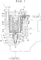
FIG. 1 is a fragmentary sectional view showing a planar structure of a valve device; -
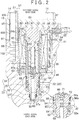
FIG. 2 is a sectional view of a solenoid valve and its vicinity; -
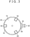
FIG. 3 is a side view of the solenoid valve; and -
FIGs. 4A to 4C are schematic views showing a procedure for assembling the solenoid valve. - Hereinafter, an embodiment of a valve device will be described with reference to the drawings. The
valve device 1 shown inFIG. 1 is assembled to agas tank 2 and controls hydrogen gas to be supplied to afuel cell 3 mounted in a vehicle. Hydrogen gas with high pressure (70 MPa, for example) is retained in thegas tank 2. - As shown in
FIG. 1 , thevalve device 1 includes abody 11, asolenoid valve 12 assembled to thebody 11 as a valve mechanism, and acover 13 that covers a portion of thesolenoid valve 12. Thecover 13 is fixed to thebody 11 bybolts 14, and thus thesolenoid valve 12 is assembled to thebody 11. For the purpose of illustration,FIG. 1 shows only thesolenoid valve 12 assembled to thebody 11, although members other than thesolenoid valve 12 including joints and various types of valve mechanisms, such as a manual valve, are assembled to thebody 11. - First, the configuration of the
body 11 will be described. Thebody 11 has a flat square box shape. Acolumnar attachment portion 21 is provided on a lower surface of thebody 11, where a surface illustrated inFIG. 1 is taken as an upper surface. Theattachment portion 21 is inserted in an attachment opening of thegas tank 2, which is not shown in the drawings. Thebody 11 according to the embodiment is made of a metal material, such as a forged aluminum alloy. Agas passage 22 and anaccommodation recess 23 are provided in thebody 11. When thebody 11 is assembled to thegas tank 2, thegas passage 22 provides communication between an inside and an outside of thegas tank 2, and the accommodation recess 23 communicates with thegas passage 22. - Specifically, the
gas passage 22 includes a connectingpassage 31, asupply passage 32, and anoutlet passage 33. The connectingpassage 31 is passed through theattachment portion 21 and connected to the inside of thegas tank 2. Thesupply passage 32 communicates with the connectingpassage 31 and opens into theaccommodation recess 23. Theoutlet passage 33 opens on a bottom surface (i.e., the deepest portion) of theaccommodation recess 23 and a side surface of thebody 11, and is connected to thefuel cell 3 as a supply destination. Theaccommodation recess 23 is a stepped circular recess. Theaccommodation recess 23 includes an outer recessedportion 34 that opens on the side surface of thebody 11, a large recessedportion 35 that opens on a bottom surface of the outer recessedportion 34, an intermediate recessedportion 36 that opens on a bottom surface of the large recessedportion 35, and a small recessedportion 37 that opens on a bottom surface of the intermediate recessedportion 36. The outer recessedportion 34 has the inner diameter larger than that of the large recessedportion 35, the large recessedportion 35 has the inner diameter larger than that of the intermediate recessedportion 36, and the intermediate recessedportion 36 has the inner diameter larger than that of the small recessedportion 37. All recessedportions extension groove 38 that extends in the axial direction of the outer recessed portion 34 (i.e., the up-down direction inFIG. 1 ) is provided in an inner periphery of the outer recessedportion 34. Connecting lines (e.g., wires or cables) 39 of a temperature sensor (not shown in the drawings) disposed in thegas tank 2, for example, are pulled out from a side surface of theextension groove 38. Thesupply passage 32 opens on an inner periphery of the large recessedportion 35. Theoutlet passage 33 is connected to a bottom surface of the small recessedportion 37. - Next, the configuration of the
solenoid valve 12 will be described. As shown inFIG. 2 , thesolenoid valve 12 includes asleeve 41, amovable core 42, a fixedcore 43, and asolenoid 44, and acase 45 as a position holding member. In the following description, a side toward which a depth of theaccommodation recess 23 increases (i.e., a side where the small recessedportion 37 is provided) is taken as a first axial end side, and a side opposite to the first axial end side is taken as a second axial end side. - The
sleeve 41 includes acylindrical portion 51 and abottom portion 52. Each of the outer diameter and the inner diameter of thecylindrical portion 51 is substantially constant along its length in the axial direction. Thebottom portion 52 has a stepped shape in which the outer diameter of thebottom portion 52 is gradually reduced toward the first axial end side. Thebottom portion 52 includes alarge diameter portion 53 that extends from thecylindrical portion 51 toward the first axial end side, anintermediate diameter portion 54 that extends from thelarge diameter portion 53 toward the first axial end side, and asmall diameter portion 55 that extends from theintermediate diameter portion 54 toward the first axial end side. The outer diameter of thelarge diameter portion 53 is substantially equal to the inner diameter of the large recessedportion 35, the outer diameter of theintermediate diameter portion 54 is substantially equal to the inner diameter of the intermediate recessedportion 36, and the outer diameter of thesmall diameter portion 55 is substantially equal to the inner diameter of the small recessedportion 37. Thesleeve 41 is accommodated in theaccommodation recess 23 in a state where thesmall diameter portion 55 fits in the small recessedportion 37, theintermediate diameter portion 54 fits in the intermediate recessedportion 36, and thelarge diameter portion 53 fits in the large recessedportion 35. In order to keep thevalve device 1 airtight, a back-upring 56a and an O-ring 56b are provided between thelarge diameter portion 53 and the large recessedportion 35, and a back-upring 57a and an O-ring 57b are provided between thesmall diameter portion 55 and the small recessedportion 37. - A communicating groove 61 that extends in the circumferential direction is provided in an outer periphery of the
large diameter portion 53. The communicating groove 61 is provided at a position in which the communicating groove 61 faces anopening position 32a of an opening of thesupply passage 32 in the inner periphery of the large recessedportion 35. An annulargroove defining member 62 is press-fitted in a portion of the communicating groove 61 on the first axial end side, and ashallow groove 63 that is shallower than the communicating groove 61 and continuous with the communicating groove 61 is provided on the second axial end side. Ametal mesh filter 65 is provided radially outward of the communicating groove 61 while being sandwiched between theshallow groove 63 and thegroove defining member 62 via sealingmembers 64. Anintroduction passage 66 that provides communication between the communicating groove 61 and an inside of the cylindrical portion 51 (i.e., a valve chamber) is provided in abottom portion 52. Theintroduction passage 66 extends linearly along the axial direction, and is provided at a position offset from the center of thebottom portion 52. On an outer periphery of thebottom portion 52 according to the embodiment, amarker 67 is provided by, for example, ink adhesion at a position overlapped with theintroduction passage 66 in the radial direction when viewed from the center of thebottom portion 52. In the drawings, themarker 67 is indicated by a solid dot for the purpose of illustration. A lead-out passage 68 that provides communication between the inside of thecylindrical portion 51 and theoutlet passage 33 is provided in thebottom portion 52. The lead-out passage 68 extends linearly along the axial direction, and is provided at the center of thebottom portion 52. Anannular valve seat 69 is fixed on an opening of theintroduction passage 66 on the second axial end side (on a side where thecylindrical portion 51 is positioned). - The
movable core 42 has a columnar shape. The outer diameter of themovable core 42 is substantially equal to the inner diameter of thecylindrical portion 51 of thesleeve 41. Themovable core 42 is accommodated in thecylindrical portion 51 so as to be movable in the axial direction. Themovable core 42 is urged by acoil spring 70 toward the first axial end side. Avalve body 71 is provided so as to be movable with themovable core 42 in the axial direction with themovable core 42. Thevalve body 71 closes the lead-out passage 68 when thevalve body 71 is placed on thevalve seat 69, and opens the lead-out passage 68 when thevalve body 71 moves away from thevalve seat 69. Themovable core 42 according to the embodiment has a mechanism generally known as the pilot valve mechanism, which allows a small amount of hydrogen gas to flow between the inside of thecylindrical portion 51 and the lead-out passage 68 before thevalve body 71 leaves thevalve seat 69 as themovable core 42 moves in the axial direction. - As shown in the
FIGs. 2 and3 , the fixedcore 43 has a stepped columnar shape. The fixedcore 43 includes abase portion 72, a press-fittedportion 73 that extends from thebase portion 72 towards the first axial end side, and aflange portion 74 that extends outwardly in the radial direction at an end of thebase portion 72 on the second axial end side. The outer diameter of the press-fittedportion 73 is substantially equal to the inner diameter of thecylindrical portion 51 of thesleeve 41, and the outer diameter of thebase portion 72 is substantially equal to the outer diameter of thecylindrical portion 51. A plurality ofpositioning grooves 75, three in the embodiment, is provided in theflange portion 74, at equal angle intervals in the circumferential direction. Each positioninggroove 75 opens outwardly, and at the same time, opens toward the second axial end side. The fixedcore 43 is fixed to thesleeve 41 such that the press-fittedportion 73 is press-fitted in thecylindrical portion 51, and a position of onepositioning groove 75 in the circumferential direction coincides with a position of themarker 67 of thesleeve 41 in the circumferential direction, that is, a position of theintroduction passage 66 in the circumferential direction. An O-ring 76 is provided between the press-fittedportion 73 and thecylindrical portion 51. - The
solenoid 44 includes acylindrical bobbin 81, acoil 82 provided around thebobbin 81, and anannular yoke 83. The inner diameter of thebobbin 81 is substantially equal to the outer diameter of thecylindrical portion 51 of thesleeve 41 as well as the outer diameter of thebase portion 72 of the fixedcore 43. A length of the bobbin 81 (the solenoid 44) along the axial direction is greater than a depth (a length along the axial direction) of the outer recessedportion 34.Flange portions flange portions flange portion 74 of the fixedcore 43. Aterminal portion 86 protrudes outwardly from theflange portion 84b provided on the second axial end side. Connecting lines (e.g., wires or cables) 85 connected to thecoil 82 extend from theterminal portion 86. Thebobbin 81 is fitted over outer peripheries of thecylindrical portion 51 and thebase portion 72 such that theterminal portion 86 and themarker 67 are positioned 180 degrees away from each other in the circumferential direction, that is, the sleeve 41 (the introduction passage 66) and the solenoid 44 (the connecting line 85) satisfy a predetermined assembled positional relationship in the circumferential direction. The inner diameter of theyoke 83 is substantially equal to the outer diameter of thecylindrical portion 51, and the outer diameter of theyoke 83 is slightly smaller than each of the outer diameters of theflange portions yoke 83 is positioned adjacent to theflange portion 84a on the first axial end side, and is fitted onto the outer periphery of thecylindrical portion 51. - The
case 45 has a cylindrical shape with a bottom portion. Each of the outer diameter and the inner diameter of theentire case 45 is substantially constant along its length in the axial direction. The inner diameter of thecase 45 is substantially equal to each of the outer diameters of theflange portions bobbin 81, and the outer diameter of thecase 45 is smaller than the inner diameter of the outer recessedportion 34. A through-hole 87 having the inner diameter, which is substantially equal to the outer diameter of thecylindrical portion 51, is provided in the bottom portion of thecase 45. A plurality ofholders 88, three in the embodiment, is provided at an opening edge of an opening of thecase 45, at equal angle intervals in the circumferential direction. Eachholder 88 extends in the axial direction. Onenotch 89 is provided in the opening edge of thecase 45, at an intermediate position between the twoadjacent holders 88. Thecase 45 is fitted onto an outer periphery of thesolenoid 44 with theterminal portion 86 projecting from thenotch 89. Eachholder 88 is bent to engage with thecorresponding positioning groove 75 of the fixedcore 43. As a result, a positional relationship in the circumferential direction between theintroduction passage 66 of thesleeve 41 and the connectinglines 85 of thesolenoid 44 that extends from theterminal portion 86 is maintained at the predetermined assembled positional relationship in which theintroduction passage 66 and the connectinglines 85 are positioned about 180 degrees away from each other. - The
solenoid valve 12 is assembled to thebody 11 such that end portions of the fixedcore 43, thesolenoid 44, and thecase 45 on the second axial end side protrude from theaccommodation recess 23, and the position of the connecting lines 85 (the terminal portion 86) in the circumferential direction substantially coincides with theopening position 32a of thesupply passage 32. As a result, theintroduction passage 66 and theopening position 32a of thesupply passage 32 are positioned 180 degrees away from each other. - Next, the configuration of the
cover 13 will be described. As shown in theFIG. 2 , thecover 13 has a generally cup shape. Thecover 13 is made of a metal material, such as a forged aluminum alloy. Acover recess 91 that opens toward the first axial end side (a side where theaccommodation recess 23 is provided) is provided in thecover 13. Thecover recess 91 is defined by a cylindrical inner periphery of thecover 13. The diameter of thecover recess 91 is substantially equal to the inner diameter of the outer recessedportion 34, and a depth of thecover recess 91 is substantially equal to a length of the portion of thesolenoid valve 12, which protrudes from theaccommodation recess 23, along the axial direction. Anextension groove 92 that extends in the axial direction and opens toward the first axial end side is provided in the inner periphery of thecover recess 91, at a position in which theextension groove 92 faces theextension groove 38 of the outer recessedportion 34. A pull-outhole 93 that extends through thecover 13 in the radial direction is provided in a bottom portion of the extension groove 92 (i.e., in a side portion of thecover 13 on which theextension groove 92 is provided). The connectinglines 85 of thesolenoid 44 and the connectinglines 39 of the above described sensors are passed through the pull-outhole 93 with agrommet 94 being interposed, and led to the outside of thevalve device 1. - A plurality of insertion holes 95, each of which passes through the
cover 13 in the axial direction, is provided around thecover recess 91 in thecover 13, at equal angle intervals in the circumferential direction. On the other hand, a plurality of threadedholes 96 is provided around theaccommodation recess 23 in thebody 11, at positions in which the threadedholes 96 face the insertion holes 95. Thebolts 14 loosely inserted into the insertion holes 95 are threaded into the threadedholes 96, and thus thecover 13 is fixed to thebody 11. Anannular gasket 97 is provided between thecover 13 and thebody 11. - Each
bolt 14 includes ahead 101, acylindrical shank 102 that extends from thehead 101 toward the first axial end side, and athread 103 that extends from theshank 102 toward the first axial end side. Thethread 103 is threaded into the threadedhole 96 with theshank 102 being disposed in theinsertion hole 95. The diameter of thehead 101 is larger than the diameter of theshank 102, and the diameter of theshank 102 is larger than the diameter of thethread 103. The diameter of theshank 102 is slightly smaller than the diameter of theinsertion hole 95, and theshank 102 is loosely fitted in theinsertion hole 95. Specifically, the diameter of theshank 102 is set such that a first gap S1 defined between theshank 102 and a wall of thecover 13, which defines theinsertion hole 95, in the perpendicular direction perpendicular to the axial direction is smaller than a second gap S2 defined between the inner periphery of thecover 13, which defines thecover recess 91, and the solenoid valve 12 (the case 45) in the perpendicular direction. - Hereinafter, the operation of the
solenoid valve 12 will be described. In thesolenoid valve 12, when driving current is not supplied to thecoil 82, themovable core 42 is urged toward thevalve seat 69 by an urging force of thecoil spring 70 and a pressure of the hydrogen gas. At this time, thevalve body 71 is placed on thevalve seat 69, and thus the lead-out passage 68 is closed. In this case, the hydrogen gas supplied from thesupply passage 32 reaches thecylindrical portion 51 via the communicating groove 61, but the hydrogen gas is not supplied to theoutlet passage 33. When the driving current is supplied to thecoil 82, on the other hand, themovable core 42 is drawn by the fixedcore 43 and moves in a direction away from thevalve seat 69, against the urging force of thecoil spring 70. Then, thevalve body 71 leaves thevalve seat 69 and thus the lead-out passage 68 is opened. In this case, after the hydrogen gas supplied from thesupply passage 32 reaches the inside of thecylindrical portion 51 via the communicating groove 61 and theintroduction passage 66, the hydrogen gas is supplied, via the lead-out passage 68, to theoutlet passage 33 and then to thefuel cell 3. - Next, the manufacturing process of the
valve device 1 according to the embodiment will be described. Thebody 11 is shaped by forging first. Subsequently, theaccommodation recess 23, thesupply passage 32, theoutlet passage 33, and others are formed by cutting. In a similar way, thecover 13 is shaped by forging, and subsequently, thecover recess 91, the pull-outhole 93, and others are formed by cutting. - The
solenoid valve 12 is assembled from components prepared in the predetermined processes, according to the following procedure. Specifically, as shown inFIG. 4A , the fixedcore 43 is fixed to thecylindrical portion 51 such that the position of onepositioning groove 75 of the fixedcore 43 in the circumferential direction coincides with the position of themarker 67 in the circumferential direction, in a state where components other than thesolenoid 44 and thecase 45, such as themovable core 42, are assembled to thesleeve 41. Next, as shown inFIG. 4B , thesolenoid 44 is fitted over the outer periphery of thesleeve 41 and the outer periphery of the fixedcore 43 such that the connecting lines 85 (the terminal portion 86) and themarker 67 are 180 degrees away from each other in the circumferential direction. Then, as shown inFIG. 4C , thecase 45 is fitted onto the outer periphery of thesolenoid 44, and as shown by the alternate long and two short dashes line inFIG. 4C , theholders 88 are bent toward thepositioning grooves 75 to maintain the positional relationship between thesleeve 41 and thesolenoid 44 in the circumferential direction at the predetermined assembled positional relationship. - After the
solenoid valve 12 is assembled as described above, thesolenoid valve 12 is inserted in theaccommodation recess 23 such that, when viewed from the center of theaccommodation recess 23, the position of the connectinglines 85 in the circumferential direction coincides with the position of theopening position 32a of thesupply passage 32 in the circumferential direction. Next, while the connectinglines hole 93 of thecover 13, thesolenoid valve 12 is covered with thecover 13 such that the portion of thesolenoid valve 12, which protrudes from theaccommodation recess 23, is accommodated in thecover recess 91, and thecover 13 is fixed to thebody 11 by thebolts 14. Then, the various types of valve mechanism other than thesolenoid valve 12 is assembled to thebody 11, and thus thevalve device 1 is manufactured. - According to the embodiment, as described above, the following functions and advantages are achieved. The
solenoid valve 12 is accommodated in theaccommodation recess 23 with the portion of thesolenoid valve 12 protruding from theaccommodation recess 23 of thebody 11, and the protruding portion of thesolenoid valve 12 is accommodated in thecover recess 91 of thecover 13. Thus, the depth of theaccommodation recess 23 can be reduced as compared with a case where thewhole solenoid valve 12 is accommodated in an accommodation recess. This facilitates formation of theaccommodation recess 23 in thebody 11. In addition, the reduced depth of theaccommodation recess 23 can reduce deformation of thebody 11, and thus the yield with respect to the material improves when thebody 11 is shaped by forging. - The first gap S1 defined between the
shank 102 and the wall of thecover 13, which defines theinsertion hole 95, is smaller than the second gap S2 defined between the inner periphery of thecover 13, which defines thecover recess 91, and thecase 45 of thesolenoid valve 12. Thus, if the position of thecover 13 with respect to thebody 11 changes when a force is applied to thecover 13, the wall of thecover 13, which defines theinsertion hole 95, is brought into contact with theshank 102 of thebolt 14 before thecover 13 is brought into contact with thesolenoid valve 12. As a result, movement of thecover 13 is restricted, which reduces the possibility of damage to thesolenoid valve 12 caused by the contact of thecover 13 with thesolenoid valve 12. - The
solenoid valve 12 is accommodated in theaccommodation recess 23 such that, theintroduction passage 66 and theopening position 32a of thesupply passage 32 are positioned 180 degrees away from each other in the circumferential direction. When thevalve device 1 is used during long time, a tiny amount of moisture contained in the hydrogen gas may be gradually collected and condensed into water drops in thesupply passage 32. In this case, if the condensed water drops enter thecylindrical portion 51 of thesleeve 41 and adhere to the members such as themovable core 42, the members to which the water drops adheres may become rusty. According to the above configuration, theintroduction passage 66 and theopening position 32a of thesupply passage 32 provided in theaccommodation recess 23 are positioned away from each other. This keeps the water drops from entering thecylindrical portion 51 of thesleeve 41 from thesupply passage 32, and thus prevents the members in thecylindrical portion 51 from becoming rusty. - The
case 45 maintains the positional relationship between thesleeve 41 and thesolenoid 44 in the circumferential direction at the predetermined assembled positional relationship. Thus, by using the connectinglines 85, provided in the portion of thesolenoid 44 protruding from theaccommodation recess 23, as a marker for putting thesolenoid valve 12 in theaccommodation recess 23, theintroduction passage 66 and theopening position 32a of thesupply passage 32 can be positioned away from each other easily. - The connecting
lines 85 are led to the outside of thevalve device 1 from the portion of thesolenoid 44 protruding from theaccommodation recess 23, via the pull-outhole 93 of thecover 13. This makes it possible to put thesolenoid valve 12 in theaccommodation recess 23 easily without need for consideration of arrangement of the connectinglines 85 and the like. - The
marker 67 is provided on the outer periphery of thesleeve 41 at the position corresponding to theintroduction passage 66. This makes it possible to position theintroduction passage 66 of thesleeve 41 and the connectinglines 85 of thesolenoid 44 such that the positional relationship between theintroduction passage 66 of thesleeve 41 and the connectinglines 85 of thesolenoid 44 in the circumferential direction satisfies the predetermined assembled positional relationship. - Instead of the above described embodiment, the invention may be carried out in the following embodiments in which the above embodiment is appropriately modified. In the above embodiment, the communicating groove 61 has an annular shape and opens outward in the radial direction. However, the invention is not limited to this, and as long as the communicating groove 61 provides communication between the
supply passage 32 and theintroduction passage 66, the connectingpassage 31 may have a circular ark shape and open outward in the radial direction. - In the above embodiment, the
marker 67 may not be provided on the outer periphery of thesleeve 41. In the above embodiment, theholders 88 of thecase 45 are bent toward thepositioning grooves 75 of the fixedcore 43 and engaged with thepositioning grooves 75 of the fixedcore 43 to hold the positions of thesleeve 41 and thesolenoid 44 in the circumferential direction. However, the invention is not limited to this, and adhesive or the like may be used to hold the positions of thesleeve 41 and thesolenoid 44 in the circumferential direction. Alternatively, thesolenoid valve 12 may be accommodated in theaccommodation recess 23 in a state where the positional relationship in the circumferential direction between thesleeve 41 and thesolenoid 44 is not maintained. - In the above embodiment, the
introduction passage 66 and theopening position 32a of thesupply passage 32 are positioned 180 degrees away from each other in the circumferential direction. However, the invention is not limited to this, and theintroduction passage 66 and theopening position 32a of thesupply passage 32 may be positioned way from each other at an angle smaller than 180 degrees. Alternatively, the position of theintroduction passage 66 in the circumferential direction may coincide with theopening position 32a of thesupply passage 32. - In the above embodiment, the first gap S1 defined between the
wall 13 of thecover 13, which defines theinsertion hole 95, and theshank 102 is smaller than the second gap S2 defined between the inner periphery of thecover 13, which defines thecover recess 91, and thecase 45 of thesolenoid valve 12. However, the first gap S1 and the second gap S2 may have the same size, or the first gap S1 may be larger than the second gap S2. In this case, thecover 13 is fixed to thebody 11 by a bolt without a shank. - In the above embodiment, the
solenoid valve 12 is assembled to thebody 11 such that thesolenoid valve 12 is accommodated in theaccommodation recess 23 with the portion of thesolenoid valve 12 protruding from theaccommodation recess 23, and the protruding portion of thesolenoid valve 12 is accommodated in thecover recess 91 of thecover 13. However, the embodiment is not limited to this, and a valve mechanism other than thesolenoid valve 12 may be assembled to thebody 11 in a similar way.
Claims (5)
- A valve device including:a body (11) including a gas passage (22) through which gas flows and an accommodation recess (23) that is a stepped circular recess and includes an outer recessed portion (34) that opens on the side surface of the body (11) and communicates with the gas passage (22);a valve mechanism (12) which controls flow of the gas flowing through the gas passage (22) and which includes a sleeve (41) including a cylindrical portion (51) and a bottom portion (52), a movable core (42) provided in the cylindrical portion so as to be movable in an axial direction of the cylindrical portion, a fixed core (43) fixed to a portion of the cylindrical portion that is closer to an opening of the cylindrical portion than the movable core is, and a solenoid (44) provided on an outer periphery of the cylindrical portion (51); anda cover (13) fixed to the body (11) such that the cover (13) covers the accommodation recess (23), the valve device characterized in that:the solenoid (44) protrudes from the accommodation recess (23);the cover (13) includes a cover recess (91) that opens toward the accommodation recess (23);the diameter of the cover recess (91) is substantially equal to the inner diameter of the outer recessed portion (34); andthe valve mechanism (12) is assembled to the body (11) such that the valve mechanism (12) is accommodated in the accommodation recess (23) with a portion of the valve mechanism (12) protruding from the accommodation recess (23) and the portion of the valve mechanism (12) is accommodated in the cover recess.
- The valve device according to claim 1, wherein:the cover (13) is fixed to the body (11) by a bolt (14);the cover (13) includes an insertion hole (95) in which the bolt (14) is loosely fitted; anda first gap defined between a wall of the cover (13), which defines the insertion hole (95), and the bolt (14) in a perpendicular direction perpendicular to an axial direction of the bolt (14) is smaller than a second gap defined between an inner periphery of the cover (13), which defines the cover recess, and the valve mechanism (12) in the perpendicular direction.
- The valve device according to claim 1 or 2, wherein:the gas passage (22) includes a supply passage (32) through which the gas is supplied from a gas tank (2) to the valve mechanism (12), and an outlet passage (33) through which the gas is supplied from the valve mechanism (12) to a supply destination (3);the supply passage (32) opens into the accommodation recess (23), and the outlet passage (33) opens in a bottom portion of the accommodation recess (23);the sleeve (41) includes a communicating groove (61) that communicates with the supply passage (32), an introduction passage (66) that provides communication between the communicating groove (61) and an inside of the cylindrical portion (51), and a lead-out passage (68) that provides communication between the inside of the cylindrical portion (51) and the outlet passage (33);the communicating groove (61) opens outwardly in a radial direction of the cylindrical portion (51), and extends in a circumferential direction of the cylindrical portion (51); andthe valve mechanism (12) is accommodated in the accommodation recess (23) such that the introduction passage (66) is positioned away from a position of an opening of the supply passage (32) in the accommodation recess (23) in the circumferential direction.
- The valve device according to claim 3, wherein:the solenoid (44) is provided with a connecting line (85) that extends from the portion of the solenoid (44), which protrudes from the accommodation recess (23); andthe valve mechanism (12) includes a position holding member (45) that holds the solenoid (44) and the sleeve (41) such that a positional relationship in the circumferential direction between the introduction passage (66) and the connecting line (85) satisfies a predetermined assembled positional relationship.
- The valve device according to claim 3 or 4, wherein a marker (67) is provided on an outer periphery of the sleeve (41) at a position corresponding to the introduction passage (66).
Applications Claiming Priority (1)
| Application Number | Priority Date | Filing Date | Title |
|---|---|---|---|
| JP2014004815A JP6305769B2 (en) | 2014-01-15 | 2014-01-15 | Valve device |
Publications (2)
| Publication Number | Publication Date |
|---|---|
| EP2896857A1 EP2896857A1 (en) | 2015-07-22 |
| EP2896857B1 true EP2896857B1 (en) | 2020-02-19 |
Family
ID=52347204
Family Applications (1)
| Application Number | Title | Priority Date | Filing Date |
|---|---|---|---|
| EP15151323.1A Active EP2896857B1 (en) | 2014-01-15 | 2015-01-15 | Valve device |
Country Status (4)
| Country | Link |
|---|---|
| US (1) | US10006559B2 (en) |
| EP (1) | EP2896857B1 (en) |
| JP (1) | JP6305769B2 (en) |
| CN (1) | CN104776261B (en) |
Cited By (2)
| Publication number | Priority date | Publication date | Assignee | Title |
|---|---|---|---|---|
| DE102022209914A1 (en) | 2022-09-21 | 2024-03-21 | Robert Bosch Gesellschaft mit beschränkter Haftung | Valve assembly for a fuel gas tank, fuel gas tank with valve assembly and fuel gas tank system |
| DE102022209694A1 (en) | 2022-09-15 | 2024-03-21 | Robert Bosch Gesellschaft mit beschränkter Haftung | Tank valve, construction kit and protective sleeve for a tank valve |
Families Citing this family (7)
| Publication number | Priority date | Publication date | Assignee | Title |
|---|---|---|---|---|
| JP6658327B2 (en) | 2015-07-01 | 2020-03-04 | Agc株式会社 | Tempered glass plate |
| JP2019158072A (en) * | 2018-03-15 | 2019-09-19 | 株式会社ジェイテクト | Electromagnetic valve device |
| CN108869796B (en) * | 2018-06-15 | 2019-12-17 | 上海理工大学 | Rotary combination valve and method for fixed bed chemical looping hydrogen production |
| JP7175208B2 (en) * | 2019-01-31 | 2022-11-18 | 川崎重工業株式会社 | Solenoid valve for gas |
| JP7266415B2 (en) * | 2019-01-31 | 2023-04-28 | 川崎重工業株式会社 | Solenoid valve for gas |
| DE102022101548A1 (en) * | 2021-02-15 | 2022-08-18 | Toyota Jidosha Kabushiki Kaisha | high pressure tank |
| JP2023006183A (en) * | 2021-06-30 | 2023-01-18 | 日本電産トーソク株式会社 | Electromagnetic valve module |
Citations (1)
| Publication number | Priority date | Publication date | Assignee | Title |
|---|---|---|---|---|
| US4538228A (en) * | 1982-02-18 | 1985-08-27 | Knorr-Bremse Gmbh | Hydraulic pressure actuated brake system for rail vehicles |
Family Cites Families (16)
| Publication number | Priority date | Publication date | Assignee | Title |
|---|---|---|---|---|
| GB867814A (en) * | 1958-06-24 | 1961-05-10 | Roger Charles Dubois | Alternating-current magnet particularly for electrically operated valves |
| US4002185A (en) * | 1975-10-24 | 1977-01-11 | Erie Manufacturing Company | Motor operated valve unit with heat dissipating clip member |
| US4124192A (en) * | 1977-02-28 | 1978-11-07 | Ambac Industries Incorporated | Time delay solenoid operated valve |
| JPH0573376U (en) * | 1992-03-13 | 1993-10-08 | 日信工業株式会社 | Solenoid valve device |
| JP2566983Y2 (en) | 1992-10-02 | 1998-03-30 | 株式会社ユニシアジェックス | Assembly of solenoid valves |
| US5845672A (en) * | 1996-12-10 | 1998-12-08 | General Motors Corporation | Solenoid coil positioning assembly |
| US6553975B2 (en) * | 2000-08-08 | 2003-04-29 | Siemens Automotive Inc. | Method of operating a fuel tank isolation valve |
| CN2490368Y (en) * | 2001-06-12 | 2002-05-08 | 贺传璞 | Fluid medium magnetic electric-controlled valve |
| US20050035319A1 (en) * | 2003-07-30 | 2005-02-17 | Satoshi Sanada | Hydraulic control system for vehicle |
| JP4158675B2 (en) | 2003-10-23 | 2008-10-01 | 株式会社ジェイテクト | solenoid valve |
| DE102006003858A1 (en) * | 2006-01-27 | 2007-08-02 | Robert Bosch Gmbh | Hydraulic valve assembly with adjacent valves positioned radially by spacer clips linked by flexible springs |
| DE102006037695A1 (en) | 2006-08-11 | 2008-02-14 | Robert Bosch Gmbh | Hydroaggreagat a vehicle brake system with a sealing element |
| DE102007055728A1 (en) * | 2006-12-15 | 2008-06-19 | Advics Co., Ltd., Kariya | Fluid pressure control device |
| JP5421059B2 (en) * | 2009-10-21 | 2014-02-19 | 豊興工業株式会社 | solenoid valve |
| DE102009055293A1 (en) | 2009-12-23 | 2011-06-30 | Robert Bosch GmbH, 70469 | Solenoid valve device |
| US8905071B2 (en) * | 2010-10-26 | 2014-12-09 | Air Lift Company | Integrated manifold system for controlling an air suspension |
-
2014
- 2014-01-15 JP JP2014004815A patent/JP6305769B2/en active Active
-
2015
- 2015-01-09 US US14/593,323 patent/US10006559B2/en active Active
- 2015-01-13 CN CN201510016273.XA patent/CN104776261B/en active Active
- 2015-01-15 EP EP15151323.1A patent/EP2896857B1/en active Active
Patent Citations (1)
| Publication number | Priority date | Publication date | Assignee | Title |
|---|---|---|---|---|
| US4538228A (en) * | 1982-02-18 | 1985-08-27 | Knorr-Bremse Gmbh | Hydraulic pressure actuated brake system for rail vehicles |
Cited By (3)
| Publication number | Priority date | Publication date | Assignee | Title |
|---|---|---|---|---|
| DE102022209694A1 (en) | 2022-09-15 | 2024-03-21 | Robert Bosch Gesellschaft mit beschränkter Haftung | Tank valve, construction kit and protective sleeve for a tank valve |
| WO2024056257A1 (en) | 2022-09-15 | 2024-03-21 | Robert Bosch Gmbh | Tank valve, modular system, and protective sleeve for a tank valve |
| DE102022209914A1 (en) | 2022-09-21 | 2024-03-21 | Robert Bosch Gesellschaft mit beschränkter Haftung | Valve assembly for a fuel gas tank, fuel gas tank with valve assembly and fuel gas tank system |
Also Published As
| Publication number | Publication date |
|---|---|
| JP2015132348A (en) | 2015-07-23 |
| JP6305769B2 (en) | 2018-04-04 |
| US20150198261A1 (en) | 2015-07-16 |
| CN104776261B (en) | 2019-11-05 |
| CN104776261A (en) | 2015-07-15 |
| US10006559B2 (en) | 2018-06-26 |
| EP2896857A1 (en) | 2015-07-22 |
Similar Documents
| Publication | Publication Date | Title |
|---|---|---|
| EP2896857B1 (en) | Valve device | |
| CA2908256C (en) | Valve device | |
| EP3015756B1 (en) | Throttle valve | |
| EP2937607B1 (en) | Valve apparatus | |
| US9080539B2 (en) | Electromagnetic fuel injection valve | |
| US10421662B2 (en) | Sensor fixing structure including valve body and pressure sensor | |
| KR20140012739A (en) | Internal pilot type pressure regulator | |
| KR20180031041A (en) | Valve core | |
| EP2535626A1 (en) | Solenoid device | |
| US10890271B2 (en) | Solenoid valve device | |
| JP2011226606A (en) | Solenoid valve | |
| CN112621164A (en) | Press fitting method, valve core assembly and electronic expansion valve | |
| JP6558980B2 (en) | Pressure fluid control device | |
| US8754732B2 (en) | Solenoid with a tube | |
| US11415238B2 (en) | Electromagnetic valve and valve device | |
| US10471943B2 (en) | Vehicle brake hydraulic pressure control apparatus and method for manufacturing the same | |
| US20180085688A1 (en) | Control valve apparatus | |
| JP2015102948A (en) | Reduction valve | |
| CN113757398A (en) | Electromagnetic valve | |
| JP2017015151A (en) | Pressure fluid control device | |
| JPH072861U (en) | Charge valve |
Legal Events
| Date | Code | Title | Description |
|---|---|---|---|
| PUAI | Public reference made under article 153(3) epc to a published international application that has entered the european phase |
Free format text: ORIGINAL CODE: 0009012 |
|
| 17P | Request for examination filed |
Effective date: 20150115 |
|
| AK | Designated contracting states |
Kind code of ref document: A1 Designated state(s): AL AT BE BG CH CY CZ DE DK EE ES FI FR GB GR HR HU IE IS IT LI LT LU LV MC MK MT NL NO PL PT RO RS SE SI SK SM TR |
|
| AX | Request for extension of the european patent |
Extension state: BA ME |
|
| 17P | Request for examination filed |
Effective date: 20160119 |
|
| RBV | Designated contracting states (corrected) |
Designated state(s): AL AT BE BG CH CY CZ DE DK EE ES FI FR GB GR HR HU IE IS IT LI LT LU LV MC MK MT NL NO PL PT RO RS SE SI SK SM TR |
|
| STAA | Information on the status of an ep patent application or granted ep patent |
Free format text: STATUS: EXAMINATION IS IN PROGRESS |
|
| 17Q | First examination report despatched |
Effective date: 20170328 |
|
| GRAP | Despatch of communication of intention to grant a patent |
Free format text: ORIGINAL CODE: EPIDOSNIGR1 |
|
| STAA | Information on the status of an ep patent application or granted ep patent |
Free format text: STATUS: GRANT OF PATENT IS INTENDED |
|
| INTG | Intention to grant announced |
Effective date: 20190925 |
|
| GRAS | Grant fee paid |
Free format text: ORIGINAL CODE: EPIDOSNIGR3 |
|
| GRAA | (expected) grant |
Free format text: ORIGINAL CODE: 0009210 |
|
| STAA | Information on the status of an ep patent application or granted ep patent |
Free format text: STATUS: THE PATENT HAS BEEN GRANTED |
|
| RIN1 | Information on inventor provided before grant (corrected) |
Inventor name: INAGI, SHUSUKE Inventor name: YAMASHITA, AKIRA Inventor name: NAKANO, AKIRA Inventor name: KUBO, TOSHIKATSU |
|
| AK | Designated contracting states |
Kind code of ref document: B1 Designated state(s): AL AT BE BG CH CY CZ DE DK EE ES FI FR GB GR HR HU IE IS IT LI LT LU LV MC MK MT NL NO PL PT RO RS SE SI SK SM TR |
|
| RAP1 | Party data changed (applicant data changed or rights of an application transferred) |
Owner name: JTEKT CORPORATION |
|
| REG | Reference to a national code |
Ref country code: CH Ref legal event code: EP |
|
| REG | Reference to a national code |
Ref country code: DE Ref legal event code: R096 Ref document number: 602015047148 Country of ref document: DE |
|
| REG | Reference to a national code |
Ref country code: AT Ref legal event code: REF Ref document number: 1235352 Country of ref document: AT Kind code of ref document: T Effective date: 20200315 |
|
| REG | Reference to a national code |
Ref country code: IE Ref legal event code: FG4D |
|
| REG | Reference to a national code |
Ref country code: NL Ref legal event code: MP Effective date: 20200219 |
|
| PG25 | Lapsed in a contracting state [announced via postgrant information from national office to epo] |
Ref country code: FI Free format text: LAPSE BECAUSE OF FAILURE TO SUBMIT A TRANSLATION OF THE DESCRIPTION OR TO PAY THE FEE WITHIN THE PRESCRIBED TIME-LIMIT Effective date: 20200219 Ref country code: NO Free format text: LAPSE BECAUSE OF FAILURE TO SUBMIT A TRANSLATION OF THE DESCRIPTION OR TO PAY THE FEE WITHIN THE PRESCRIBED TIME-LIMIT Effective date: 20200519 Ref country code: RS Free format text: LAPSE BECAUSE OF FAILURE TO SUBMIT A TRANSLATION OF THE DESCRIPTION OR TO PAY THE FEE WITHIN THE PRESCRIBED TIME-LIMIT Effective date: 20200219 |
|
| REG | Reference to a national code |
Ref country code: LT Ref legal event code: MG4D |
|
| PG25 | Lapsed in a contracting state [announced via postgrant information from national office to epo] |
Ref country code: BG Free format text: LAPSE BECAUSE OF FAILURE TO SUBMIT A TRANSLATION OF THE DESCRIPTION OR TO PAY THE FEE WITHIN THE PRESCRIBED TIME-LIMIT Effective date: 20200519 Ref country code: LV Free format text: LAPSE BECAUSE OF FAILURE TO SUBMIT A TRANSLATION OF THE DESCRIPTION OR TO PAY THE FEE WITHIN THE PRESCRIBED TIME-LIMIT Effective date: 20200219 Ref country code: IS Free format text: LAPSE BECAUSE OF FAILURE TO SUBMIT A TRANSLATION OF THE DESCRIPTION OR TO PAY THE FEE WITHIN THE PRESCRIBED TIME-LIMIT Effective date: 20200619 Ref country code: SE Free format text: LAPSE BECAUSE OF FAILURE TO SUBMIT A TRANSLATION OF THE DESCRIPTION OR TO PAY THE FEE WITHIN THE PRESCRIBED TIME-LIMIT Effective date: 20200219 Ref country code: HR Free format text: LAPSE BECAUSE OF FAILURE TO SUBMIT A TRANSLATION OF THE DESCRIPTION OR TO PAY THE FEE WITHIN THE PRESCRIBED TIME-LIMIT Effective date: 20200219 Ref country code: GR Free format text: LAPSE BECAUSE OF FAILURE TO SUBMIT A TRANSLATION OF THE DESCRIPTION OR TO PAY THE FEE WITHIN THE PRESCRIBED TIME-LIMIT Effective date: 20200520 |
|
| PG25 | Lapsed in a contracting state [announced via postgrant information from national office to epo] |
Ref country code: NL Free format text: LAPSE BECAUSE OF FAILURE TO SUBMIT A TRANSLATION OF THE DESCRIPTION OR TO PAY THE FEE WITHIN THE PRESCRIBED TIME-LIMIT Effective date: 20200219 |
|
| PG25 | Lapsed in a contracting state [announced via postgrant information from national office to epo] |
Ref country code: SM Free format text: LAPSE BECAUSE OF FAILURE TO SUBMIT A TRANSLATION OF THE DESCRIPTION OR TO PAY THE FEE WITHIN THE PRESCRIBED TIME-LIMIT Effective date: 20200219 Ref country code: EE Free format text: LAPSE BECAUSE OF FAILURE TO SUBMIT A TRANSLATION OF THE DESCRIPTION OR TO PAY THE FEE WITHIN THE PRESCRIBED TIME-LIMIT Effective date: 20200219 Ref country code: DK Free format text: LAPSE BECAUSE OF FAILURE TO SUBMIT A TRANSLATION OF THE DESCRIPTION OR TO PAY THE FEE WITHIN THE PRESCRIBED TIME-LIMIT Effective date: 20200219 Ref country code: ES Free format text: LAPSE BECAUSE OF FAILURE TO SUBMIT A TRANSLATION OF THE DESCRIPTION OR TO PAY THE FEE WITHIN THE PRESCRIBED TIME-LIMIT Effective date: 20200219 Ref country code: LT Free format text: LAPSE BECAUSE OF FAILURE TO SUBMIT A TRANSLATION OF THE DESCRIPTION OR TO PAY THE FEE WITHIN THE PRESCRIBED TIME-LIMIT Effective date: 20200219 Ref country code: CZ Free format text: LAPSE BECAUSE OF FAILURE TO SUBMIT A TRANSLATION OF THE DESCRIPTION OR TO PAY THE FEE WITHIN THE PRESCRIBED TIME-LIMIT Effective date: 20200219 Ref country code: RO Free format text: LAPSE BECAUSE OF FAILURE TO SUBMIT A TRANSLATION OF THE DESCRIPTION OR TO PAY THE FEE WITHIN THE PRESCRIBED TIME-LIMIT Effective date: 20200219 Ref country code: SK Free format text: LAPSE BECAUSE OF FAILURE TO SUBMIT A TRANSLATION OF THE DESCRIPTION OR TO PAY THE FEE WITHIN THE PRESCRIBED TIME-LIMIT Effective date: 20200219 Ref country code: PT Free format text: LAPSE BECAUSE OF FAILURE TO SUBMIT A TRANSLATION OF THE DESCRIPTION OR TO PAY THE FEE WITHIN THE PRESCRIBED TIME-LIMIT Effective date: 20200712 |
|
| REG | Reference to a national code |
Ref country code: AT Ref legal event code: MK05 Ref document number: 1235352 Country of ref document: AT Kind code of ref document: T Effective date: 20200219 |
|
| REG | Reference to a national code |
Ref country code: DE Ref legal event code: R097 Ref document number: 602015047148 Country of ref document: DE |
|
| PLBE | No opposition filed within time limit |
Free format text: ORIGINAL CODE: 0009261 |
|
| STAA | Information on the status of an ep patent application or granted ep patent |
Free format text: STATUS: NO OPPOSITION FILED WITHIN TIME LIMIT |
|
| 26N | No opposition filed |
Effective date: 20201120 |
|
| PG25 | Lapsed in a contracting state [announced via postgrant information from national office to epo] |
Ref country code: AT Free format text: LAPSE BECAUSE OF FAILURE TO SUBMIT A TRANSLATION OF THE DESCRIPTION OR TO PAY THE FEE WITHIN THE PRESCRIBED TIME-LIMIT Effective date: 20200219 Ref country code: IT Free format text: LAPSE BECAUSE OF FAILURE TO SUBMIT A TRANSLATION OF THE DESCRIPTION OR TO PAY THE FEE WITHIN THE PRESCRIBED TIME-LIMIT Effective date: 20200219 |
|
| PG25 | Lapsed in a contracting state [announced via postgrant information from national office to epo] |
Ref country code: PL Free format text: LAPSE BECAUSE OF FAILURE TO SUBMIT A TRANSLATION OF THE DESCRIPTION OR TO PAY THE FEE WITHIN THE PRESCRIBED TIME-LIMIT Effective date: 20200219 Ref country code: SI Free format text: LAPSE BECAUSE OF FAILURE TO SUBMIT A TRANSLATION OF THE DESCRIPTION OR TO PAY THE FEE WITHIN THE PRESCRIBED TIME-LIMIT Effective date: 20200219 |
|
| PG25 | Lapsed in a contracting state [announced via postgrant information from national office to epo] |
Ref country code: MC Free format text: LAPSE BECAUSE OF FAILURE TO SUBMIT A TRANSLATION OF THE DESCRIPTION OR TO PAY THE FEE WITHIN THE PRESCRIBED TIME-LIMIT Effective date: 20200219 |
|
| REG | Reference to a national code |
Ref country code: CH Ref legal event code: PL |
|
| GBPC | Gb: european patent ceased through non-payment of renewal fee |
Effective date: 20210115 |
|
| PG25 | Lapsed in a contracting state [announced via postgrant information from national office to epo] |
Ref country code: LU Free format text: LAPSE BECAUSE OF NON-PAYMENT OF DUE FEES Effective date: 20210115 |
|
| REG | Reference to a national code |
Ref country code: BE Ref legal event code: MM Effective date: 20210131 |
|
| PG25 | Lapsed in a contracting state [announced via postgrant information from national office to epo] |
Ref country code: GB Free format text: LAPSE BECAUSE OF NON-PAYMENT OF DUE FEES Effective date: 20210115 Ref country code: CH Free format text: LAPSE BECAUSE OF NON-PAYMENT OF DUE FEES Effective date: 20210131 Ref country code: LI Free format text: LAPSE BECAUSE OF NON-PAYMENT OF DUE FEES Effective date: 20210131 |
|
| PG25 | Lapsed in a contracting state [announced via postgrant information from national office to epo] |
Ref country code: IE Free format text: LAPSE BECAUSE OF NON-PAYMENT OF DUE FEES Effective date: 20210115 |
|
| PG25 | Lapsed in a contracting state [announced via postgrant information from national office to epo] |
Ref country code: BE Free format text: LAPSE BECAUSE OF NON-PAYMENT OF DUE FEES Effective date: 20210131 |
|
| PG25 | Lapsed in a contracting state [announced via postgrant information from national office to epo] |
Ref country code: HU Free format text: LAPSE BECAUSE OF FAILURE TO SUBMIT A TRANSLATION OF THE DESCRIPTION OR TO PAY THE FEE WITHIN THE PRESCRIBED TIME-LIMIT; INVALID AB INITIO Effective date: 20150115 |
|
| PGFP | Annual fee paid to national office [announced via postgrant information from national office to epo] |
Ref country code: DE Payment date: 20221130 Year of fee payment: 9 |
|
| PG25 | Lapsed in a contracting state [announced via postgrant information from national office to epo] |
Ref country code: CY Free format text: LAPSE BECAUSE OF FAILURE TO SUBMIT A TRANSLATION OF THE DESCRIPTION OR TO PAY THE FEE WITHIN THE PRESCRIBED TIME-LIMIT Effective date: 20200219 |
|
| PGFP | Annual fee paid to national office [announced via postgrant information from national office to epo] |
Ref country code: FR Payment date: 20231212 Year of fee payment: 10 |