EP2896786B1 - Turbinenrotoranordnungen mit verbesserten Spalthohlräumen - Google Patents
Turbinenrotoranordnungen mit verbesserten Spalthohlräumen Download PDFInfo
- Publication number
- EP2896786B1 EP2896786B1 EP15151181.3A EP15151181A EP2896786B1 EP 2896786 B1 EP2896786 B1 EP 2896786B1 EP 15151181 A EP15151181 A EP 15151181A EP 2896786 B1 EP2896786 B1 EP 2896786B1
- Authority
- EP
- European Patent Office
- Prior art keywords
- turbine rotor
- base surface
- turbine
- rotor assembly
- slot
- Prior art date
- Legal status (The legal status is an assumption and is not a legal conclusion. Google has not performed a legal analysis and makes no representation as to the accuracy of the status listed.)
- Active
Links
Images


Classifications
-
- F—MECHANICAL ENGINEERING; LIGHTING; HEATING; WEAPONS; BLASTING
- F01—MACHINES OR ENGINES IN GENERAL; ENGINE PLANTS IN GENERAL; STEAM ENGINES
- F01D—NON-POSITIVE DISPLACEMENT MACHINES OR ENGINES, e.g. STEAM TURBINES
- F01D5/00—Blades; Blade-carrying members; Heating, heat-insulating, cooling or antivibration means on the blades or the members
- F01D5/02—Blade-carrying members, e.g. rotors
- F01D5/04—Blade-carrying members, e.g. rotors for radial-flow machines or engines
-
- F—MECHANICAL ENGINEERING; LIGHTING; HEATING; WEAPONS; BLASTING
- F01—MACHINES OR ENGINES IN GENERAL; ENGINE PLANTS IN GENERAL; STEAM ENGINES
- F01D—NON-POSITIVE DISPLACEMENT MACHINES OR ENGINES, e.g. STEAM TURBINES
- F01D5/00—Blades; Blade-carrying members; Heating, heat-insulating, cooling or antivibration means on the blades or the members
- F01D5/02—Blade-carrying members, e.g. rotors
- F01D5/08—Heating, heat-insulating or cooling means
- F01D5/081—Cooling fluid being directed on the side of the rotor disc or at the roots of the blades
-
- F—MECHANICAL ENGINEERING; LIGHTING; HEATING; WEAPONS; BLASTING
- F01—MACHINES OR ENGINES IN GENERAL; ENGINE PLANTS IN GENERAL; STEAM ENGINES
- F01D—NON-POSITIVE DISPLACEMENT MACHINES OR ENGINES, e.g. STEAM TURBINES
- F01D5/00—Blades; Blade-carrying members; Heating, heat-insulating, cooling or antivibration means on the blades or the members
- F01D5/12—Blades
- F01D5/14—Form or construction
- F01D5/18—Hollow blades, i.e. blades with cooling or heating channels or cavities; Heating, heat-insulating or cooling means on blades
-
- F—MECHANICAL ENGINEERING; LIGHTING; HEATING; WEAPONS; BLASTING
- F01—MACHINES OR ENGINES IN GENERAL; ENGINE PLANTS IN GENERAL; STEAM ENGINES
- F01D—NON-POSITIVE DISPLACEMENT MACHINES OR ENGINES, e.g. STEAM TURBINES
- F01D5/00—Blades; Blade-carrying members; Heating, heat-insulating, cooling or antivibration means on the blades or the members
- F01D5/30—Fixing blades to rotors; Blade roots ; Blade spacers
- F01D5/3007—Fixing blades to rotors; Blade roots ; Blade spacers of axial insertion type
-
- F—MECHANICAL ENGINEERING; LIGHTING; HEATING; WEAPONS; BLASTING
- F05—INDEXING SCHEMES RELATING TO ENGINES OR PUMPS IN VARIOUS SUBCLASSES OF CLASSES F01-F04
- F05D—INDEXING SCHEME FOR ASPECTS RELATING TO NON-POSITIVE-DISPLACEMENT MACHINES OR ENGINES, GAS-TURBINES OR JET-PROPULSION PLANTS
- F05D2230/00—Manufacture
- F05D2230/60—Assembly methods
-
- Y—GENERAL TAGGING OF NEW TECHNOLOGICAL DEVELOPMENTS; GENERAL TAGGING OF CROSS-SECTIONAL TECHNOLOGIES SPANNING OVER SEVERAL SECTIONS OF THE IPC; TECHNICAL SUBJECTS COVERED BY FORMER USPC CROSS-REFERENCE ART COLLECTIONS [XRACs] AND DIGESTS
- Y02—TECHNOLOGIES OR APPLICATIONS FOR MITIGATION OR ADAPTATION AGAINST CLIMATE CHANGE
- Y02T—CLIMATE CHANGE MITIGATION TECHNOLOGIES RELATED TO TRANSPORTATION
- Y02T50/00—Aeronautics or air transport
- Y02T50/60—Efficient propulsion technologies, e.g. for aircraft
-
- Y—GENERAL TAGGING OF NEW TECHNOLOGICAL DEVELOPMENTS; GENERAL TAGGING OF CROSS-SECTIONAL TECHNOLOGIES SPANNING OVER SEVERAL SECTIONS OF THE IPC; TECHNICAL SUBJECTS COVERED BY FORMER USPC CROSS-REFERENCE ART COLLECTIONS [XRACs] AND DIGESTS
- Y10—TECHNICAL SUBJECTS COVERED BY FORMER USPC
- Y10T—TECHNICAL SUBJECTS COVERED BY FORMER US CLASSIFICATION
- Y10T29/00—Metal working
- Y10T29/49—Method of mechanical manufacture
- Y10T29/49316—Impeller making
- Y10T29/4932—Turbomachine making
- Y10T29/49321—Assembling individual fluid flow interacting members, e.g., blades, vanes, buckets, on rotary support member
Definitions
- the compressor section 130 may include a series of compressors that raise the pressure of the air directed into it from the fan section 120.
- the compressors may direct the compressed air into the combustion section 140.
- the combustion section 140 the high pressure air is mixed with fuel and combusted.
- the combusted air is then directed into the turbine section 150.
- the turbine section 150 may include a series of rotor and stator assemblies disposed in axial flow series.
- the combusted air from the combustion section 140 expands through the rotor and stator assemblies and causes the rotor assemblies to rotate a main engine shaft for energy extraction.
- the air is then exhausted through a propulsion nozzle disposed in the exhaust section 160 to provide additional forward thrust.
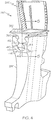
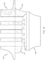
- the base surface 370 defines one or more feed inlets 372, 373, 374, 375 (shown in dashed lines).
- the feed inlets 372-375 are coupled to fluid passages that extend through the attachment portion 360 and into the airfoil 310 as part of a cooling system, as described in greater detail below.
- Four feed inlets 372-375 are arranged in an axial row in the embodiment of FIG. 3 , although any number or pattern of such feed inlets may be provided.
- the slot cavity 450 is configured to receive cooling air at the cavity inlet 452 and direct the cooling air into the feed inlets 372-375 ( FIG. 3 ). The remaining cooling air is directed out of the slot cavity 450 through the slot cavity outlet.
- the cooling air flowing through the feed inlets 372-375 functions to cool various portions of the rotor blade 260, while cooling air exiting the slot cavity outlet may function to cool the rear face of the rotor disk 280 and/or attachment portion 360.
- the base surface 370 of the rotor blade 260 may be sized and shaped to provide desired flow characteristics through the slot cavity 450 and into the feed inlets 372-375.
- the increase in depth of the attachment portion 360 and corresponding decrease in cross-sectional area functions to reduce undesired flow structures, such as vortices, particularly mid-channel vortices and aft-channel vortices. Reducing such vortices decreases uneven and detrimental pressure distributions, thereby leading to improved flow delivery to the feed inlets 372-375 and uniform pressure distributions and blade flow control.
- Computational fluid dynamic (CFD) analysis may be used to optimize the location and orientation of the base surface 370.
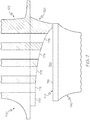
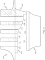
- each feed inlet 672-675 may increase in depth along the axial length of the respective inlet 672-675, as indicated by the dashed line spanning each inlet 672-675.
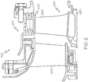
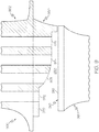
- FIG. 9 is a partial cross-sectional view of a turbine rotor assembly 900 in accordance with an exemplary embodiment.
- the view of the turbine rotor assembly 900 corresponds to the view of the turbine rotor assembly 250 of FIG. 5 .
- the discussion of turbine rotor assembly 250 of FIG. 5 is also applicable to the turbine rotor assembly 900 of FIG. 9 .
- the turbine rotor assembly 900 may be incorporated into the turbine section of the gas turbine engines discussed above.
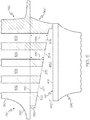
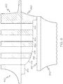
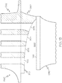
- the turbine rotor assembly 1400 includes a turbine rotor blade 1402 with an attachment portion 1460 mounted in a slot 1410 of a rotor disk 1480 to form a slot cavity 1450 between a base surface 1470 and a slot bottom 1416.
- Feed inlets 1472, 1473, 1474, 1475 are formed in the base surface 1470.
- the base surface 1470 has a generally curved shape with an increasing depth, thereby decreasing the cross-sectional area of the slot cavity 1450 and enhancing flow characteristics.
- FIG. 17 is a flow chart of a method 1700 for forming a turbine rotor assembly (e.g., turbine rotor assemblies 250, 600, 700, 800, 900, 1000, 1100, 1200, 1300, 1400, 1500, 1600 of FIGS. 5-16 ) in accordance with an exemplary embodiment.
- a turbine rotor assembly e.g., turbine rotor assemblies 250, 600, 700, 800, 900, 1000, 1100, 1200, 1300, 1400, 1500, 1600 of FIGS. 5-16 .
- a baseline turbine rotor assembly is considered, for example, with CFD analysis to evaluate flow characteristics.
- such turbine rotor assemblies correspond to the turbine rotor assemblies discussed above in which turbine rotor blades are mounted on a rotor disk in a turbine section.
- each turbine rotor blade forms a slot cavity with the rotor disk to direct air through the slot cavity and into inlet feeds for cooling.
- the baseline turbine rotor assembly may include a rotor blade with a flattened bottom surface such that a slot cavity with a generally constant cross-sectional area is formed.
- the turbine rotor blade is formed. Any suitable manufacturing technique may be provided, including casting and additive manufacturing techniques. Typically, in this step, the turbine rotor blade is formed with a flat base surface.
- the turbine rotor blade is mounted onto the rotor disk with similar turbine rotor blades for assembly into the turbine section of a gas turbine engine.
Landscapes
- Engineering & Computer Science (AREA)
- Mechanical Engineering (AREA)
- General Engineering & Computer Science (AREA)
- Turbine Rotor Nozzle Sealing (AREA)
Claims (7)
- Turbinenrotorflügel (260, 602, 702, 802, 902, 1002, 1102, 1202, 1302, 1402, 1502, 1602), der Folgendes umfasst:eine Plattform (350) mit einer ersten Seite und einer zweiten Seite;einen Tragflügel (310), der sich von der ersten Seite der Plattform (350) erstreckt, dadurch gekennzeichnet, dass er ferner Folgendes umfasst:einen Befestigungsabschnitt (360, 660, 760, 860, 960, 1060, 1160, 1260, 1360, 1460, 1560, 1660), der sich von der zweiten Seite der Plattform (350) erstreckt, wobei der Befestigungsabschnitt (360, 660, 760, 860, 960, 1060, 1160, 1260, 1360, 1460, 1560, 1660) erste und zweite seitliche Oberflächen und eine Basisoberfläche (370, 670, 770, 870, 970, 1070, 1170, 1270, 1370, 1470, 1570, 1670) an einer Unterseite des Befestigungsabschnitts (360, 660, 760, 860, 960, 1060, 1160, 1260, 1360, 1460, 1560, 1660) zwischen der ersten und zweiten seitlichen Oberfläche beinhaltet, und wobei die Basisoberfläche (370, 670, 770, 870, 970, 1070, 1170, 1270, 1370, 1470, 1570, 1670) mindestens ein gewölbtes Segment oder angewinkeltes Segment beinhaltet, wobei die Basisoberfläche (370, 670, 770, 870, 970, 1070, 1170, 1270, 1370, 1470, 1570, 1670) einen Spalthohlraum (450, 650, 750, 850, 950, 1050, 1150, 1250, 1350, 1450, 1550, 1650) ausbildet mit einer flachen Spaltunterseite (416, 616, 816, 916, 1016, 1116, 1216, 1316, 1416, 1516, 1616) und Fluiddurchgängen (572) mit Zuführeinlässen (372-375, 472-475, 572-575, 672-675, 772-775, 872-875, 972-975, 1072-1075, 1172-1175, 1272-1275, 1372-1375, 1472-1475 1572-1575, 1672-1675), definiert in der Basisoberfläche (370, 670, 770, 870, 970, 1070, 1170, 1270, 1370, 1470, 1570, 1670) in einer axialen Reihe,wobei die Basisoberfläche (370, 670, 770, 870, 970, 1070, 1170, 1270, 1370, 1470, 1570, 1670) so geformt ist, dass der Spalthohlraum (450, 650, 750, 850, 950, 1050, 1150, 1250, 1350, 1450, 1550, 1650) eine Querschnittsfläche aufweist, die sich entlang einer allgemein axialen Richtung von einem vorderen Ende zu einem hinteren Ende verkleinert, undwobei die Zuführeinlässe (372-375, 472-475, 572-575, 572-575, 672-675, 772-775, 872-875, 972-975, 1072-1075, 1172-1175, 1272-1275, 1372-1375, 1472-1475, 1572-1575, 1672-1675) so in der Basisoberfläche (370, 670, 770, 870, 970, 1070, 1170, 1270, 1370, 1470, 1570, 1670) positioniert sind, dass sich eine radiale Tiefe jedes Zuführeinlasses (372-375, 472-475, 572-575, 672-675, 772-775, 872-875, 972-975, 1072-1075, 1172-1175, 1272-1275, 1372-1375, 1472-1475, 1572-1575, 1672-1675) entlang der allgemein axialen Richtung vergrößert.
- Turbinenrotorflügel (702, 1202, 1302) nach Anspruch 1, wobei die Basisoberfläche (770, 1270, 1370) mindestens ein konkaves Segment beinhaltet.
- Turbinenrotorflügel (802, 902, 1102, 1202, 1402, 1502) nach Anspruch 1, wobei die Basisoberfläche (870, 970, 1170, 1270, 1470, 1570) mindestens ein konvexes Segment beinhaltet.
- Turbinenrotorflügel (1002) nach Anspruch 1, wobei die Basisoberfläche (1070) eine Vielzahl der angewinkelten Segmente beinhaltet, die jeweils eine unterschiedliche Neigung aufweisen.
- Turbinenrotorflügel (1202) nach Anspruch 1, wobei die Basisoberfläche (1270) mindestens ein konkaves Segment und mindestens ein konvexes Segment beinhaltet.
- Turbinenrotorflügel (902, 1102) nach Anspruch 1, wobei die Basisoberfläche (970, 1170) mindestens ein gewölbtes Segment und mindestens ein angewinkeltes Segment beinhaltet.
- Turbinenrotorflügel (1402, 1502) nach Anspruch 6, wobei die Zuführeinlässe (1472-1475, 1572-1575) schaufelartig sind.
Applications Claiming Priority (1)
| Application Number | Priority Date | Filing Date | Title |
|---|---|---|---|
| US14/159,043 US9777575B2 (en) | 2014-01-20 | 2014-01-20 | Turbine rotor assemblies with improved slot cavities |
Publications (2)
| Publication Number | Publication Date |
|---|---|
| EP2896786A1 EP2896786A1 (de) | 2015-07-22 |
| EP2896786B1 true EP2896786B1 (de) | 2019-03-13 |
Family
ID=52347183
Family Applications (1)
| Application Number | Title | Priority Date | Filing Date |
|---|---|---|---|
| EP15151181.3A Active EP2896786B1 (de) | 2014-01-20 | 2015-01-14 | Turbinenrotoranordnungen mit verbesserten Spalthohlräumen |
Country Status (2)
| Country | Link |
|---|---|
| US (1) | US9777575B2 (de) |
| EP (1) | EP2896786B1 (de) |
Families Citing this family (6)
| Publication number | Priority date | Publication date | Assignee | Title |
|---|---|---|---|---|
| FR3043133B1 (fr) * | 2015-10-30 | 2020-09-18 | Turbomeca | Aube de turbomachine comprenant un pied etage et traverse par des cavites d'air de refroidissement |
| US10047611B2 (en) | 2016-01-28 | 2018-08-14 | United Technologies Corporation | Turbine blade attachment curved rib stiffeners |
| US10683763B2 (en) | 2016-10-04 | 2020-06-16 | Honeywell International Inc. | Turbine blade with integral flow meter |
| US10648354B2 (en) | 2016-12-02 | 2020-05-12 | Honeywell International Inc. | Turbine wheels, turbine engines including the same, and methods of forming turbine wheels with improved seal plate sealing |
| KR101984397B1 (ko) * | 2017-09-29 | 2019-05-30 | 두산중공업 주식회사 | 로터, 터빈 및 이를 포함하는 가스터빈 |
| FR3087479B1 (fr) | 2018-10-23 | 2022-05-13 | Safran Aircraft Engines | Aube de turbomachine |
Family Cites Families (22)
| Publication number | Priority date | Publication date | Assignee | Title |
|---|---|---|---|---|
| NL88170C (de) * | 1952-10-31 | 1900-01-01 | ||
| US2848193A (en) | 1953-04-08 | 1958-08-19 | Gen Electric | Air cooled turbomachine blading |
| BE530261A (de) | 1953-07-11 | |||
| GB853586A (en) | 1957-06-15 | 1960-11-09 | Rolls Royce | Improved turbine blades, compressor blades and method of manufacturing the same |
| DE1173732B (de) | 1960-06-08 | 1964-07-09 | Gen Motors Corp | Gegossene Turbinenschaufel |
| NL124984C (de) | 1963-10-29 | |||
| GB1350471A (en) * | 1971-05-06 | 1974-04-18 | Secr Defence | Gas turbine engine |
| FR2485632B1 (fr) | 1980-06-30 | 1985-07-05 | Snecma | Perfectionnement aux systemes de ventilation des aubes et disques de turbines |
| USRE33954E (en) * | 1982-02-22 | 1992-06-09 | United Technologies Corporation | Rotor blade assembly |
| US4451205A (en) * | 1982-02-22 | 1984-05-29 | United Technologies Corporation | Rotor blade assembly |
| JPS59108805A (ja) | 1982-12-15 | 1984-06-23 | Toshiba Corp | タ−ビン動翼の固定装置 |
| US4820126A (en) | 1988-02-22 | 1989-04-11 | Westinghouse Electric Corp. | Turbomachine rotor assembly having reduced stress concentrations |
| US5403156A (en) | 1993-10-26 | 1995-04-04 | United Technologies Corporation | Integral meter plate for turbine blade and method |
| EP1041246A1 (de) | 1999-03-29 | 2000-10-04 | Siemens Aktiengesellschaft | Kühlmitteldurchströmte, gegossene Gasturbinenschaufel sowie Vorrichtung und Verfahren zur Herstellung eines Verteilerraums der Gasturbinenschaufel |
| EP1136654A1 (de) | 2000-03-21 | 2001-09-26 | Siemens Aktiengesellschaft | Turbinenlaufschaufel |
| US6786696B2 (en) | 2002-05-06 | 2004-09-07 | General Electric Company | Root notched turbine blade |
| US6932570B2 (en) | 2002-05-23 | 2005-08-23 | General Electric Company | Methods and apparatus for extending gas turbine engine airfoils useful life |
| US7442007B2 (en) * | 2005-06-02 | 2008-10-28 | Pratt & Whitney Canada Corp. | Angled blade firtree retaining system |
| EP2090751A1 (de) | 2008-02-15 | 2009-08-19 | Siemens Aktiengesellschaft | Laufschaufel für eine Turbomaschine |
| JP5379585B2 (ja) | 2009-07-15 | 2013-12-25 | 株式会社日立製作所 | 動翼装着部洗浄機能を備えた蒸気タービン |
| US8622702B1 (en) * | 2010-04-21 | 2014-01-07 | Florida Turbine Technologies, Inc. | Turbine blade with cooling air inlet holes |
| US8939711B2 (en) * | 2013-02-15 | 2015-01-27 | Siemens Aktiengesellschaft | Outer rim seal assembly in a turbine engine |
-
2014
- 2014-01-20 US US14/159,043 patent/US9777575B2/en active Active
-
2015
- 2015-01-14 EP EP15151181.3A patent/EP2896786B1/de active Active
Non-Patent Citations (1)
| Title |
|---|
| None * |
Also Published As
| Publication number | Publication date |
|---|---|
| US20150204194A1 (en) | 2015-07-23 |
| US9777575B2 (en) | 2017-10-03 |
| EP2896786A1 (de) | 2015-07-22 |
Similar Documents
| Publication | Publication Date | Title |
|---|---|---|
| US10934856B2 (en) | Gas turbine engines with improved leading edge airfoil cooling | |
| US9546554B2 (en) | Gas turbine engine components with blade tip cooling | |
| EP2787174B1 (de) | Gasturbinentriebwerke mit gekühlte Schaufeln | |
| EP2896786B1 (de) | Turbinenrotoranordnungen mit verbesserten Spalthohlräumen | |
| EP2716866B1 (de) | Gasturbinenmotorkomponenten mit seitlich und vorwärts laufenden Filmkühlbohrungen | |
| US9879544B2 (en) | Turbine rotor blades with improved tip portion cooling holes | |
| US8337146B2 (en) | Rotor casing treatment with recessed baffles | |
| EP2388435A2 (de) | Turbinenrotorschaufel mit gekühlter Plattform | |
| EP2634370B1 (de) | Turbinenschaufel mit einem Kernhohlraum mit einer konturierten Drehung | |
| EP2848769B1 (de) | Verfahren zur herstellung einer turbinenlaufschaufel | |
| US9816389B2 (en) | Turbine rotor blades with tip portion parapet wall cavities | |
| US11199099B2 (en) | Gas turbine engines with improved airfoil dust removal | |
| EP2971545B1 (de) | Mit niedrigem druckverlust gekühlte schaufel | |
| US20160186577A1 (en) | Cooling configurations for turbine blades | |
| EP3203026B1 (de) | Gasturbinenschaufel mit sockelanordnung |
Legal Events
| Date | Code | Title | Description |
|---|---|---|---|
| PUAI | Public reference made under article 153(3) epc to a published international application that has entered the european phase |
Free format text: ORIGINAL CODE: 0009012 |
|
| 17P | Request for examination filed |
Effective date: 20150114 |
|
| AK | Designated contracting states |
Kind code of ref document: A1 Designated state(s): AL AT BE BG CH CY CZ DE DK EE ES FI FR GB GR HR HU IE IS IT LI LT LU LV MC MK MT NL NO PL PT RO RS SE SI SK SM TR |
|
| AX | Request for extension of the european patent |
Extension state: BA ME |
|
| RAP1 | Party data changed (applicant data changed or rights of an application transferred) |
Owner name: HONEYWELL INTERNATIONAL INC. |
|
| REG | Reference to a national code |
Ref country code: DE Ref legal event code: R079 Ref document number: 602015026152 Country of ref document: DE Free format text: PREVIOUS MAIN CLASS: F01D0005080000 Ipc: F01D0005040000 |
|
| RIC1 | Information provided on ipc code assigned before grant |
Ipc: F01D 5/18 20060101ALI20180627BHEP Ipc: F01D 5/08 20060101ALI20180627BHEP Ipc: F01D 5/30 20060101ALI20180627BHEP Ipc: F01D 5/04 20060101AFI20180627BHEP |
|
| GRAP | Despatch of communication of intention to grant a patent |
Free format text: ORIGINAL CODE: EPIDOSNIGR1 |
|
| STAA | Information on the status of an ep patent application or granted ep patent |
Free format text: STATUS: GRANT OF PATENT IS INTENDED |
|
| INTG | Intention to grant announced |
Effective date: 20180806 |
|
| RIN1 | Information on inventor provided before grant (corrected) |
Inventor name: HARMAN, STUART ANDREW Inventor name: HALFMANN, STEVE Inventor name: TAPIA, LUIS |
|
| GRAS | Grant fee paid |
Free format text: ORIGINAL CODE: EPIDOSNIGR3 |
|
| GRAA | (expected) grant |
Free format text: ORIGINAL CODE: 0009210 |
|
| STAA | Information on the status of an ep patent application or granted ep patent |
Free format text: STATUS: THE PATENT HAS BEEN GRANTED |
|
| AK | Designated contracting states |
Kind code of ref document: B1 Designated state(s): AL AT BE BG CH CY CZ DE DK EE ES FI FR GB GR HR HU IE IS IT LI LT LU LV MC MK MT NL NO PL PT RO RS SE SI SK SM TR |
|
| REG | Reference to a national code |
Ref country code: GB Ref legal event code: FG4D |
|
| REG | Reference to a national code |
Ref country code: AT Ref legal event code: REF Ref document number: 1107930 Country of ref document: AT Kind code of ref document: T Effective date: 20190315 Ref country code: CH Ref legal event code: EP |
|
| REG | Reference to a national code |
Ref country code: IE Ref legal event code: FG4D |
|
| REG | Reference to a national code |
Ref country code: DE Ref legal event code: R096 Ref document number: 602015026152 Country of ref document: DE |
|
| REG | Reference to a national code |
Ref country code: NL Ref legal event code: MP Effective date: 20190313 |
|
| REG | Reference to a national code |
Ref country code: LT Ref legal event code: MG4D |
|
| PG25 | Lapsed in a contracting state [announced via postgrant information from national office to epo] |
Ref country code: LT Free format text: LAPSE BECAUSE OF FAILURE TO SUBMIT A TRANSLATION OF THE DESCRIPTION OR TO PAY THE FEE WITHIN THE PRESCRIBED TIME-LIMIT Effective date: 20190313 Ref country code: NO Free format text: LAPSE BECAUSE OF FAILURE TO SUBMIT A TRANSLATION OF THE DESCRIPTION OR TO PAY THE FEE WITHIN THE PRESCRIBED TIME-LIMIT Effective date: 20190613 Ref country code: FI Free format text: LAPSE BECAUSE OF FAILURE TO SUBMIT A TRANSLATION OF THE DESCRIPTION OR TO PAY THE FEE WITHIN THE PRESCRIBED TIME-LIMIT Effective date: 20190313 Ref country code: SE Free format text: LAPSE BECAUSE OF FAILURE TO SUBMIT A TRANSLATION OF THE DESCRIPTION OR TO PAY THE FEE WITHIN THE PRESCRIBED TIME-LIMIT Effective date: 20190313 |
|
| PG25 | Lapsed in a contracting state [announced via postgrant information from national office to epo] |
Ref country code: BG Free format text: LAPSE BECAUSE OF FAILURE TO SUBMIT A TRANSLATION OF THE DESCRIPTION OR TO PAY THE FEE WITHIN THE PRESCRIBED TIME-LIMIT Effective date: 20190613 Ref country code: NL Free format text: LAPSE BECAUSE OF FAILURE TO SUBMIT A TRANSLATION OF THE DESCRIPTION OR TO PAY THE FEE WITHIN THE PRESCRIBED TIME-LIMIT Effective date: 20190313 Ref country code: RS Free format text: LAPSE BECAUSE OF FAILURE TO SUBMIT A TRANSLATION OF THE DESCRIPTION OR TO PAY THE FEE WITHIN THE PRESCRIBED TIME-LIMIT Effective date: 20190313 Ref country code: LV Free format text: LAPSE BECAUSE OF FAILURE TO SUBMIT A TRANSLATION OF THE DESCRIPTION OR TO PAY THE FEE WITHIN THE PRESCRIBED TIME-LIMIT Effective date: 20190313 Ref country code: HR Free format text: LAPSE BECAUSE OF FAILURE TO SUBMIT A TRANSLATION OF THE DESCRIPTION OR TO PAY THE FEE WITHIN THE PRESCRIBED TIME-LIMIT Effective date: 20190313 Ref country code: GR Free format text: LAPSE BECAUSE OF FAILURE TO SUBMIT A TRANSLATION OF THE DESCRIPTION OR TO PAY THE FEE WITHIN THE PRESCRIBED TIME-LIMIT Effective date: 20190614 |
|
| REG | Reference to a national code |
Ref country code: AT Ref legal event code: MK05 Ref document number: 1107930 Country of ref document: AT Kind code of ref document: T Effective date: 20190313 |
|
| PG25 | Lapsed in a contracting state [announced via postgrant information from national office to epo] |
Ref country code: PT Free format text: LAPSE BECAUSE OF FAILURE TO SUBMIT A TRANSLATION OF THE DESCRIPTION OR TO PAY THE FEE WITHIN THE PRESCRIBED TIME-LIMIT Effective date: 20190713 Ref country code: AL Free format text: LAPSE BECAUSE OF FAILURE TO SUBMIT A TRANSLATION OF THE DESCRIPTION OR TO PAY THE FEE WITHIN THE PRESCRIBED TIME-LIMIT Effective date: 20190313 Ref country code: SK Free format text: LAPSE BECAUSE OF FAILURE TO SUBMIT A TRANSLATION OF THE DESCRIPTION OR TO PAY THE FEE WITHIN THE PRESCRIBED TIME-LIMIT Effective date: 20190313 Ref country code: EE Free format text: LAPSE BECAUSE OF FAILURE TO SUBMIT A TRANSLATION OF THE DESCRIPTION OR TO PAY THE FEE WITHIN THE PRESCRIBED TIME-LIMIT Effective date: 20190313 Ref country code: RO Free format text: LAPSE BECAUSE OF FAILURE TO SUBMIT A TRANSLATION OF THE DESCRIPTION OR TO PAY THE FEE WITHIN THE PRESCRIBED TIME-LIMIT Effective date: 20190313 Ref country code: CZ Free format text: LAPSE BECAUSE OF FAILURE TO SUBMIT A TRANSLATION OF THE DESCRIPTION OR TO PAY THE FEE WITHIN THE PRESCRIBED TIME-LIMIT Effective date: 20190313 Ref country code: ES Free format text: LAPSE BECAUSE OF FAILURE TO SUBMIT A TRANSLATION OF THE DESCRIPTION OR TO PAY THE FEE WITHIN THE PRESCRIBED TIME-LIMIT Effective date: 20190313 Ref country code: IT Free format text: LAPSE BECAUSE OF FAILURE TO SUBMIT A TRANSLATION OF THE DESCRIPTION OR TO PAY THE FEE WITHIN THE PRESCRIBED TIME-LIMIT Effective date: 20190313 |
|
| PG25 | Lapsed in a contracting state [announced via postgrant information from national office to epo] |
Ref country code: SM Free format text: LAPSE BECAUSE OF FAILURE TO SUBMIT A TRANSLATION OF THE DESCRIPTION OR TO PAY THE FEE WITHIN THE PRESCRIBED TIME-LIMIT Effective date: 20190313 Ref country code: PL Free format text: LAPSE BECAUSE OF FAILURE TO SUBMIT A TRANSLATION OF THE DESCRIPTION OR TO PAY THE FEE WITHIN THE PRESCRIBED TIME-LIMIT Effective date: 20190313 |
|
| REG | Reference to a national code |
Ref country code: DE Ref legal event code: R097 Ref document number: 602015026152 Country of ref document: DE |
|
| PG25 | Lapsed in a contracting state [announced via postgrant information from national office to epo] |
Ref country code: IS Free format text: LAPSE BECAUSE OF FAILURE TO SUBMIT A TRANSLATION OF THE DESCRIPTION OR TO PAY THE FEE WITHIN THE PRESCRIBED TIME-LIMIT Effective date: 20190713 Ref country code: AT Free format text: LAPSE BECAUSE OF FAILURE TO SUBMIT A TRANSLATION OF THE DESCRIPTION OR TO PAY THE FEE WITHIN THE PRESCRIBED TIME-LIMIT Effective date: 20190313 |
|
| PLBE | No opposition filed within time limit |
Free format text: ORIGINAL CODE: 0009261 |
|
| STAA | Information on the status of an ep patent application or granted ep patent |
Free format text: STATUS: NO OPPOSITION FILED WITHIN TIME LIMIT |
|
| PG25 | Lapsed in a contracting state [announced via postgrant information from national office to epo] |
Ref country code: DK Free format text: LAPSE BECAUSE OF FAILURE TO SUBMIT A TRANSLATION OF THE DESCRIPTION OR TO PAY THE FEE WITHIN THE PRESCRIBED TIME-LIMIT Effective date: 20190313 |
|
| 26N | No opposition filed |
Effective date: 20191216 |
|
| PG25 | Lapsed in a contracting state [announced via postgrant information from national office to epo] |
Ref country code: SI Free format text: LAPSE BECAUSE OF FAILURE TO SUBMIT A TRANSLATION OF THE DESCRIPTION OR TO PAY THE FEE WITHIN THE PRESCRIBED TIME-LIMIT Effective date: 20190313 |
|
| PG25 | Lapsed in a contracting state [announced via postgrant information from national office to epo] |
Ref country code: TR Free format text: LAPSE BECAUSE OF FAILURE TO SUBMIT A TRANSLATION OF THE DESCRIPTION OR TO PAY THE FEE WITHIN THE PRESCRIBED TIME-LIMIT Effective date: 20190313 |
|
| PGFP | Annual fee paid to national office [announced via postgrant information from national office to epo] |
Ref country code: DE Payment date: 20200131 Year of fee payment: 6 |
|
| PG25 | Lapsed in a contracting state [announced via postgrant information from national office to epo] |
Ref country code: MC Free format text: LAPSE BECAUSE OF FAILURE TO SUBMIT A TRANSLATION OF THE DESCRIPTION OR TO PAY THE FEE WITHIN THE PRESCRIBED TIME-LIMIT Effective date: 20190313 |
|
| REG | Reference to a national code |
Ref country code: CH Ref legal event code: PL |
|
| GBPC | Gb: european patent ceased through non-payment of renewal fee |
Effective date: 20200114 |
|
| REG | Reference to a national code |
Ref country code: BE Ref legal event code: MM Effective date: 20200131 |
|
| PG25 | Lapsed in a contracting state [announced via postgrant information from national office to epo] |
Ref country code: LU Free format text: LAPSE BECAUSE OF NON-PAYMENT OF DUE FEES Effective date: 20200114 Ref country code: GB Free format text: LAPSE BECAUSE OF NON-PAYMENT OF DUE FEES Effective date: 20200114 Ref country code: FR Free format text: LAPSE BECAUSE OF NON-PAYMENT OF DUE FEES Effective date: 20200131 |
|
| PG25 | Lapsed in a contracting state [announced via postgrant information from national office to epo] |
Ref country code: CH Free format text: LAPSE BECAUSE OF NON-PAYMENT OF DUE FEES Effective date: 20200131 Ref country code: BE Free format text: LAPSE BECAUSE OF NON-PAYMENT OF DUE FEES Effective date: 20200131 Ref country code: LI Free format text: LAPSE BECAUSE OF NON-PAYMENT OF DUE FEES Effective date: 20200131 |
|
| PG25 | Lapsed in a contracting state [announced via postgrant information from national office to epo] |
Ref country code: IE Free format text: LAPSE BECAUSE OF NON-PAYMENT OF DUE FEES Effective date: 20200114 |
|
| REG | Reference to a national code |
Ref country code: DE Ref legal event code: R119 Ref document number: 602015026152 Country of ref document: DE |
|
| PG25 | Lapsed in a contracting state [announced via postgrant information from national office to epo] |
Ref country code: DE Free format text: LAPSE BECAUSE OF NON-PAYMENT OF DUE FEES Effective date: 20210803 |
|
| PG25 | Lapsed in a contracting state [announced via postgrant information from national office to epo] |
Ref country code: MT Free format text: LAPSE BECAUSE OF FAILURE TO SUBMIT A TRANSLATION OF THE DESCRIPTION OR TO PAY THE FEE WITHIN THE PRESCRIBED TIME-LIMIT Effective date: 20190313 Ref country code: CY Free format text: LAPSE BECAUSE OF FAILURE TO SUBMIT A TRANSLATION OF THE DESCRIPTION OR TO PAY THE FEE WITHIN THE PRESCRIBED TIME-LIMIT Effective date: 20190313 |
|
| PG25 | Lapsed in a contracting state [announced via postgrant information from national office to epo] |
Ref country code: MK Free format text: LAPSE BECAUSE OF FAILURE TO SUBMIT A TRANSLATION OF THE DESCRIPTION OR TO PAY THE FEE WITHIN THE PRESCRIBED TIME-LIMIT Effective date: 20190313 |
|
| P01 | Opt-out of the competence of the unified patent court (upc) registered |
Effective date: 20230525 |