EP2896786B1 - Turbine rotor assemblies with improved slot cavities - Google Patents
Turbine rotor assemblies with improved slot cavities Download PDFInfo
- Publication number
- EP2896786B1 EP2896786B1 EP15151181.3A EP15151181A EP2896786B1 EP 2896786 B1 EP2896786 B1 EP 2896786B1 EP 15151181 A EP15151181 A EP 15151181A EP 2896786 B1 EP2896786 B1 EP 2896786B1
- Authority
- EP
- European Patent Office
- Prior art keywords
- turbine rotor
- base surface
- turbine
- rotor assembly
- slot
- Prior art date
- Legal status (The legal status is an assumption and is not a legal conclusion. Google has not performed a legal analysis and makes no representation as to the accuracy of the status listed.)
- Active
Links
- 238000000429 assembly Methods 0.000 title description 19
- 230000000712 assembly Effects 0.000 title description 19
- 230000007423 decrease Effects 0.000 claims description 11
- 239000012530 fluid Substances 0.000 claims description 4
- 238000001816 cooling Methods 0.000 description 44
- 239000007789 gas Substances 0.000 description 31
- 230000003247 decreasing effect Effects 0.000 description 14
- 230000002708 enhancing effect Effects 0.000 description 14
- 230000004323 axial length Effects 0.000 description 11
- 238000000034 method Methods 0.000 description 7
- 238000002485 combustion reaction Methods 0.000 description 5
- 238000009826 distribution Methods 0.000 description 5
- 239000000567 combustion gas Substances 0.000 description 3
- 239000000446 fuel Substances 0.000 description 3
- 239000000463 material Substances 0.000 description 3
- PXHVJJICTQNCMI-UHFFFAOYSA-N Nickel Chemical compound [Ni] PXHVJJICTQNCMI-UHFFFAOYSA-N 0.000 description 2
- 229910045601 alloy Inorganic materials 0.000 description 2
- 239000000956 alloy Substances 0.000 description 2
- 238000000605 extraction Methods 0.000 description 2
- 238000004519 manufacturing process Methods 0.000 description 2
- 238000012986 modification Methods 0.000 description 2
- 230000004048 modification Effects 0.000 description 2
- 238000011144 upstream manufacturing Methods 0.000 description 2
- 229910000831 Steel Inorganic materials 0.000 description 1
- 229910001069 Ti alloy Inorganic materials 0.000 description 1
- 239000000654 additive Substances 0.000 description 1
- 230000000996 additive effect Effects 0.000 description 1
- 230000002411 adverse Effects 0.000 description 1
- 230000009286 beneficial effect Effects 0.000 description 1
- 230000005540 biological transmission Effects 0.000 description 1
- 230000015572 biosynthetic process Effects 0.000 description 1
- 238000005266 casting Methods 0.000 description 1
- 238000010276 construction Methods 0.000 description 1
- 230000008878 coupling Effects 0.000 description 1
- 238000010168 coupling process Methods 0.000 description 1
- 238000005859 coupling reaction Methods 0.000 description 1
- 239000013078 crystal Substances 0.000 description 1
- 230000001419 dependent effect Effects 0.000 description 1
- 238000013461 design Methods 0.000 description 1
- 230000001627 detrimental effect Effects 0.000 description 1
- 230000000694 effects Effects 0.000 description 1
- 230000005611 electricity Effects 0.000 description 1
- 230000008030 elimination Effects 0.000 description 1
- 238000003379 elimination reaction Methods 0.000 description 1
- 238000011156 evaluation Methods 0.000 description 1
- 238000000227 grinding Methods 0.000 description 1
- 238000003754 machining Methods 0.000 description 1
- 230000013011 mating Effects 0.000 description 1
- 230000007246 mechanism Effects 0.000 description 1
- 229910052759 nickel Inorganic materials 0.000 description 1
- 238000013021 overheating Methods 0.000 description 1
- 238000005086 pumping Methods 0.000 description 1
- 230000009467 reduction Effects 0.000 description 1
- 239000010959 steel Substances 0.000 description 1
- 238000013022 venting Methods 0.000 description 1
Images


Classifications
-
- F—MECHANICAL ENGINEERING; LIGHTING; HEATING; WEAPONS; BLASTING
- F01—MACHINES OR ENGINES IN GENERAL; ENGINE PLANTS IN GENERAL; STEAM ENGINES
- F01D—NON-POSITIVE DISPLACEMENT MACHINES OR ENGINES, e.g. STEAM TURBINES
- F01D5/00—Blades; Blade-carrying members; Heating, heat-insulating, cooling or antivibration means on the blades or the members
- F01D5/02—Blade-carrying members, e.g. rotors
- F01D5/04—Blade-carrying members, e.g. rotors for radial-flow machines or engines
-
- F—MECHANICAL ENGINEERING; LIGHTING; HEATING; WEAPONS; BLASTING
- F01—MACHINES OR ENGINES IN GENERAL; ENGINE PLANTS IN GENERAL; STEAM ENGINES
- F01D—NON-POSITIVE DISPLACEMENT MACHINES OR ENGINES, e.g. STEAM TURBINES
- F01D5/00—Blades; Blade-carrying members; Heating, heat-insulating, cooling or antivibration means on the blades or the members
- F01D5/02—Blade-carrying members, e.g. rotors
- F01D5/08—Heating, heat-insulating or cooling means
- F01D5/081—Cooling fluid being directed on the side of the rotor disc or at the roots of the blades
-
- F—MECHANICAL ENGINEERING; LIGHTING; HEATING; WEAPONS; BLASTING
- F01—MACHINES OR ENGINES IN GENERAL; ENGINE PLANTS IN GENERAL; STEAM ENGINES
- F01D—NON-POSITIVE DISPLACEMENT MACHINES OR ENGINES, e.g. STEAM TURBINES
- F01D5/00—Blades; Blade-carrying members; Heating, heat-insulating, cooling or antivibration means on the blades or the members
- F01D5/12—Blades
- F01D5/14—Form or construction
- F01D5/18—Hollow blades, i.e. blades with cooling or heating channels or cavities; Heating, heat-insulating or cooling means on blades
-
- F—MECHANICAL ENGINEERING; LIGHTING; HEATING; WEAPONS; BLASTING
- F01—MACHINES OR ENGINES IN GENERAL; ENGINE PLANTS IN GENERAL; STEAM ENGINES
- F01D—NON-POSITIVE DISPLACEMENT MACHINES OR ENGINES, e.g. STEAM TURBINES
- F01D5/00—Blades; Blade-carrying members; Heating, heat-insulating, cooling or antivibration means on the blades or the members
- F01D5/30—Fixing blades to rotors; Blade roots ; Blade spacers
- F01D5/3007—Fixing blades to rotors; Blade roots ; Blade spacers of axial insertion type
-
- F—MECHANICAL ENGINEERING; LIGHTING; HEATING; WEAPONS; BLASTING
- F05—INDEXING SCHEMES RELATING TO ENGINES OR PUMPS IN VARIOUS SUBCLASSES OF CLASSES F01-F04
- F05D—INDEXING SCHEME FOR ASPECTS RELATING TO NON-POSITIVE-DISPLACEMENT MACHINES OR ENGINES, GAS-TURBINES OR JET-PROPULSION PLANTS
- F05D2230/00—Manufacture
- F05D2230/60—Assembly methods
-
- Y—GENERAL TAGGING OF NEW TECHNOLOGICAL DEVELOPMENTS; GENERAL TAGGING OF CROSS-SECTIONAL TECHNOLOGIES SPANNING OVER SEVERAL SECTIONS OF THE IPC; TECHNICAL SUBJECTS COVERED BY FORMER USPC CROSS-REFERENCE ART COLLECTIONS [XRACs] AND DIGESTS
- Y02—TECHNOLOGIES OR APPLICATIONS FOR MITIGATION OR ADAPTATION AGAINST CLIMATE CHANGE
- Y02T—CLIMATE CHANGE MITIGATION TECHNOLOGIES RELATED TO TRANSPORTATION
- Y02T50/00—Aeronautics or air transport
- Y02T50/60—Efficient propulsion technologies, e.g. for aircraft
-
- Y—GENERAL TAGGING OF NEW TECHNOLOGICAL DEVELOPMENTS; GENERAL TAGGING OF CROSS-SECTIONAL TECHNOLOGIES SPANNING OVER SEVERAL SECTIONS OF THE IPC; TECHNICAL SUBJECTS COVERED BY FORMER USPC CROSS-REFERENCE ART COLLECTIONS [XRACs] AND DIGESTS
- Y10—TECHNICAL SUBJECTS COVERED BY FORMER USPC
- Y10T—TECHNICAL SUBJECTS COVERED BY FORMER US CLASSIFICATION
- Y10T29/00—Metal working
- Y10T29/49—Method of mechanical manufacture
- Y10T29/49316—Impeller making
- Y10T29/4932—Turbomachine making
- Y10T29/49321—Assembling individual fluid flow interacting members, e.g., blades, vanes, buckets, on rotary support member
Definitions
- the compressor section 130 may include a series of compressors that raise the pressure of the air directed into it from the fan section 120.
- the compressors may direct the compressed air into the combustion section 140.
- the combustion section 140 the high pressure air is mixed with fuel and combusted.
- the combusted air is then directed into the turbine section 150.
- the turbine section 150 may include a series of rotor and stator assemblies disposed in axial flow series.
- the combusted air from the combustion section 140 expands through the rotor and stator assemblies and causes the rotor assemblies to rotate a main engine shaft for energy extraction.
- the air is then exhausted through a propulsion nozzle disposed in the exhaust section 160 to provide additional forward thrust.
- the base surface 370 defines one or more feed inlets 372, 373, 374, 375 (shown in dashed lines).
- the feed inlets 372-375 are coupled to fluid passages that extend through the attachment portion 360 and into the airfoil 310 as part of a cooling system, as described in greater detail below.
- Four feed inlets 372-375 are arranged in an axial row in the embodiment of FIG. 3 , although any number or pattern of such feed inlets may be provided.
- the slot cavity 450 is configured to receive cooling air at the cavity inlet 452 and direct the cooling air into the feed inlets 372-375 ( FIG. 3 ). The remaining cooling air is directed out of the slot cavity 450 through the slot cavity outlet.
- the cooling air flowing through the feed inlets 372-375 functions to cool various portions of the rotor blade 260, while cooling air exiting the slot cavity outlet may function to cool the rear face of the rotor disk 280 and/or attachment portion 360.
- the base surface 370 of the rotor blade 260 may be sized and shaped to provide desired flow characteristics through the slot cavity 450 and into the feed inlets 372-375.
- the increase in depth of the attachment portion 360 and corresponding decrease in cross-sectional area functions to reduce undesired flow structures, such as vortices, particularly mid-channel vortices and aft-channel vortices. Reducing such vortices decreases uneven and detrimental pressure distributions, thereby leading to improved flow delivery to the feed inlets 372-375 and uniform pressure distributions and blade flow control.
- Computational fluid dynamic (CFD) analysis may be used to optimize the location and orientation of the base surface 370.
- each feed inlet 672-675 may increase in depth along the axial length of the respective inlet 672-675, as indicated by the dashed line spanning each inlet 672-675.
- FIG. 9 is a partial cross-sectional view of a turbine rotor assembly 900 in accordance with an exemplary embodiment.
- the view of the turbine rotor assembly 900 corresponds to the view of the turbine rotor assembly 250 of FIG. 5 .
- the discussion of turbine rotor assembly 250 of FIG. 5 is also applicable to the turbine rotor assembly 900 of FIG. 9 .
- the turbine rotor assembly 900 may be incorporated into the turbine section of the gas turbine engines discussed above.
- the turbine rotor assembly 1400 includes a turbine rotor blade 1402 with an attachment portion 1460 mounted in a slot 1410 of a rotor disk 1480 to form a slot cavity 1450 between a base surface 1470 and a slot bottom 1416.
- Feed inlets 1472, 1473, 1474, 1475 are formed in the base surface 1470.
- the base surface 1470 has a generally curved shape with an increasing depth, thereby decreasing the cross-sectional area of the slot cavity 1450 and enhancing flow characteristics.
- FIG. 17 is a flow chart of a method 1700 for forming a turbine rotor assembly (e.g., turbine rotor assemblies 250, 600, 700, 800, 900, 1000, 1100, 1200, 1300, 1400, 1500, 1600 of FIGS. 5-16 ) in accordance with an exemplary embodiment.
- a turbine rotor assembly e.g., turbine rotor assemblies 250, 600, 700, 800, 900, 1000, 1100, 1200, 1300, 1400, 1500, 1600 of FIGS. 5-16 .
- a baseline turbine rotor assembly is considered, for example, with CFD analysis to evaluate flow characteristics.
- such turbine rotor assemblies correspond to the turbine rotor assemblies discussed above in which turbine rotor blades are mounted on a rotor disk in a turbine section.
- each turbine rotor blade forms a slot cavity with the rotor disk to direct air through the slot cavity and into inlet feeds for cooling.
- the baseline turbine rotor assembly may include a rotor blade with a flattened bottom surface such that a slot cavity with a generally constant cross-sectional area is formed.
- the turbine rotor blade is formed. Any suitable manufacturing technique may be provided, including casting and additive manufacturing techniques. Typically, in this step, the turbine rotor blade is formed with a flat base surface.
- the turbine rotor blade is mounted onto the rotor disk with similar turbine rotor blades for assembly into the turbine section of a gas turbine engine.
Landscapes
- Engineering & Computer Science (AREA)
- Mechanical Engineering (AREA)
- General Engineering & Computer Science (AREA)
- Turbine Rotor Nozzle Sealing (AREA)
Description
- The inventive subject matter generally relates to turbine rotor assemblies, and more particularly relates to cooling the turbine rotor blades of the turbine rotor assemblies.
- Gas turbine engines are generally used in a wide range of applications, such as aircraft engines and auxiliary power units. In a gas turbine engine, air is compressed in a compressor, mixed with fuel, and ignited in a combustor to generate hot combustion gases, which flow downstream into a turbine section. In a typical configuration, the turbine section includes rows of airfoils, such as stator vanes and rotor blades, disposed in an alternating sequence along the axial length of a generally annular hot gas flow path. The rotor blades are mounted at the periphery of one or more rotor disks that are coupled in turn to a main engine shaft. Hot combustion gases are delivered from the engine combustor to the annular hot gas flow path, thus resulting in rotary driving of the rotor disks to provide an engine output.
- Due to the high temperatures in many gas turbine engine applications, it is desirable to regulate the operating temperature of certain engine components, particularly those within the mainstream hot gas flow path in order to prevent overheating and potential mechanical issues attributable thereto. Operating temperatures may be, for example, 1100°C. As such, it is desirable to cool the rotor blades and stator vanes to prevent or reduce adverse impact and extend useful life. Mechanisms for cooling turbine rotor blades include ducting cooling air through internal passages and then venting the cooling air through holes formed in the airfoil. Internal and film cooling techniques attempt to maintain temperatures that are suitable for material and stress level.
EP0043300 describes a turbine rotor blade with improved cooling. However, despite these advances, cooling remains a challenge, particularly considering the pressure and flow losses that may occur as cooling air is directed to the areas that require cooling. - Accordingly, it is desirable to have turbine rotor assemblies with an improved manner for cooling while maintaining or improving engine efficiency. Furthermore, other desirable features and characteristics of the inventive subject matter will become apparent from the subsequent detailed description of the inventive subject matter and the appended claims, taken in conjunction with the accompanying drawings and this background of the inventive subject matter.
- In accordance with the present invention, a turbine rotor blade includes a platform with a first side and a second side; an airfoil extending from the first side of the platform; and an attachment portion extending from the second side of the platform. The attachment portion includes first and second side surfaces and a base surface on an underside of the attachment portion between the first and second side surface. The base surface includes at least one curved segment or angled segment.
- The turbine rotor blade includes a platform with a first side and a second side; an airfoil extending from the first side of the platform; and an attachment portion extending from the second side of the platform and arranged within the first slot of the rotor disk. The attachment portion includes first and second side surfaces and a base surface. The attachment portion includes feed inlets defined in the base surface for receiving cooling air. The base surface and the slot bottom define a slot cavity with a slot inlet, the slot cavity configured to receive the cooling air through the slot inlet and direct the cooling air into the feed inlets. The slot cavity has a cross-sectional area that decreases along a generally axial direction. The feed inlets are positioned in the base surface such that a radial depth of each feed inlet increases along the generally axial direction.
- The inventive subject matter will hereinafter be described in conjunction with the following drawing figures, wherein like numerals denote like elements, and
-
FIG. 1 is a partial cross-sectional view of a gas turbine engine in accordance with an exemplary embodiment; -
FIG. 2 is a partial, sectional elevation view of a portion of a turbine section of the gas turbine engine ofFIG. 1 in accordance with an exemplary embodiment; -
FIG. 3 is an isometric view of a turbine rotor blade of the turbine section ofFIG. 2 in accordance with an exemplary embodiment; -
FIG. 4 is a partial, isometric view of a turbine rotor assembly of the turbine section ofFIG. 2 in accordance with an exemplary embodiment; -
FIG. 5 is a partial, cross-sectional view of the turbine rotor assembly through line 5-5 ofFIG. 4 in accordance with an exemplary embodiment; -
FIGS. 6-16 are partial, cross-sectional views of turbine rotor assemblies in accordance with alternate exemplary embodiments; and -
FIG. 17 is a flow chart of a method for forming a turbine rotor assembly in accordance with an exemplary embodiment. - The following detailed description is merely exemplary in nature and is not intended to limit the inventive subject matter or the application and uses of the inventive subject matter. Furthermore, there is no intention to be bound by any theory presented in the preceding background or the following detailed description.
- Exemplary embodiments discussed herein are directed to turbine rotor assemblies capable of providing improved cooling performance and/or efficiency. Generally, the improved turbine rotor assemblies include a turbine rotor blade with an attachment portion having a base surface forming a slot cavity with a slot bottom of a turbine rotor disk. Cooling air is directed into and through the slot cavity to feed inlets in the base surface. The feed inlets direct the cooling air through internal passages to various portions of the turbine rotor blade. In the exemplary embodiments discussed below, the base surface of the attachment portion is oriented such that the cross-sectional area of the slot cavity decreases along the axial length. The decreasing cross-sectional area may function to improve flow characteristics of the cooling air through the slot cavity and into the feed inlets.
-
FIG. 1 is a cross-sectional view of agas turbine engine 100 according to an exemplary embodiment. AlthoughFIG. 1 depicts a turbofan engine, in general, exemplary embodiments discussed herein may be applicable to any type of engine, including turboshaft engines. Thegas turbine engine 100 may form part of, for example, an auxiliary power unit for an aircraft or a propulsion system for an aircraft. Thegas turbine engine 100 has an overall construction and operation that is generally understood by persons skilled in the art. Thegas turbine engine 100 may be disposed in anengine case 101 and may include afan section 120, acompressor section 130, acombustion section 140, aturbine section 150, and anexhaust section 160. Thefan section 120 may include a fan, which draws in and accelerates air. A fraction of the accelerated air from thefan section 120 is directed through abypass section 170 to provide a forward thrust. The remaining fraction of air exhausted from the fan is directed into thecompressor section 130. - The
compressor section 130 may include a series of compressors that raise the pressure of the air directed into it from thefan section 120. The compressors may direct the compressed air into thecombustion section 140. In thecombustion section 140, the high pressure air is mixed with fuel and combusted. The combusted air is then directed into theturbine section 150. As described in further detail below, theturbine section 150 may include a series of rotor and stator assemblies disposed in axial flow series. The combusted air from thecombustion section 140 expands through the rotor and stator assemblies and causes the rotor assemblies to rotate a main engine shaft for energy extraction. The air is then exhausted through a propulsion nozzle disposed in theexhaust section 160 to provide additional forward thrust. -
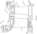
FIG. 2 is a partial, cross-sectional side view of a turbine section of an engine, such as theturbine section 150 of thegas turbine engine 100 ofFIG. 1 in accordance with an exemplary embodiment. Theturbine section 150 includes aturbine stator assembly 200 and aturbine rotor assembly 250 surrounded by ashroud 210 defining a gas flow path through which hot, combusted air from an upstream compressor section (e.g. compressor section 130 ofFIG. 1 ) is directed. Although only oneturbine stator assembly 200 and oneturbine rotor assembly 250 are shown,such stator assemblies 200 androtor assemblies 250 are typically arranged in alternating axially spaced, circumferential rows. As used herein, the term "axial" refers to a direction generally parallel to the engine centerline, while the term "radial" refers to a direction generally perpendicular to the engine centerline. - The
rotor assembly 250 generally includes rotor blades 260 (one of which is shown) mounted on a rotor disk 280 (partially shown), which in turn is coupled to an engine shaft (not shown). Theturbine stator assembly 200 directs the air toward theturbine rotor assembly 250. The air impinges uponrotor blades 260 of theturbine rotor assembly 250, thereby driving theturbine rotor assembly 250 for power extraction. To allow theturbine section 150 to operate at desirable elevated temperatures, certain components are cooled. For example, therotor assembly 250 may be cooled as described in greater detail below. -
FIG. 3 illustrates an exemplary aircraft jet engine turbine rotor blade, such asrotor blade 260 ofFIG. 2 , removed from a turbine section.FIG. 3 depicts one exemplary embodiment, and other exemplary embodiments may have alternate configurations or arrangements. - The
rotor blade 260 includes anairfoil 310, aplatform 350, and an attachment portion (or base portion or root) 360. Theplatform 350 is configured to radially contain turbine airflow within a shroud (e.g.,shroud 210 ofFIG. 2 ). Theattachment portion 360 extends from the underside of theplatform 350 and is configured to couple theblade 260 to a turbine rotor disc (not shown). In this manner, a circumferential ring ofblades 260 may be formed about the rotor disc for rotation. In general, theturbine rotor blade 260 may be made from any suitable material, including high heat and high stress resistant aerospace alloys, such as nickel based alloys, Rene 88, Mar-M-247, single crystal materials, steels, titanium alloys or the like. - The
airfoil 310 projects radially outwardly from theplatform 350. Theairfoil 310 has two side (or outer)walls first side wall 312 defines a suction side with a generally convex shape, and thesecond side wall 314 defines a pressure side with a generally concave shape. In a chordwise direction, theairfoil side walls leading edge 316 and trailingedge 318. As used herein, the term "chordwise" refers to a generally longitudinal dimension along the airfoil from leading edge to trailing edge, typically curved for air flow characteristics. In an axial direction, theairfoil side walls platform base 324 to a tip portion (or blade tip) 320 is positioned to rotate in close proximity to the shroud 210 (FIG. 2 ). - In one exemplary embodiment, the
attachment portion 360 has a "fir tree" configuration formed by aforward end face 362, anaft end face 364,side walls base surface 370. As shown, theside walls rotor blade 260 onto therotor disk 280, as described in greater detail below. Generally, thebase surface 370 forms the underside or bottom of therotor blade 260. In one exemplary embodiment, theside walls base surface 370 is non-parallel to theside walls base surface 370, generally between a forward edge and an aft edge, extends in a plane or surface that is non-parallel in a radial dimension relative to theside walls platform 350, as discussed below. As a result, thebase surface 370 has a generally angled or curved configuration or arrangement. - In one exemplary embodiment, the
base surface 370 defines one ormore feed inlets attachment portion 360 and into theairfoil 310 as part of a cooling system, as described in greater detail below. Four feed inlets 372-375 are arranged in an axial row in the embodiment ofFIG. 3 , although any number or pattern of such feed inlets may be provided. - As noted above, the
turbine rotor blade 260, particularly theairfoil 310, is subject to extremely high temperatures resulting from high velocity hot gases ducted from the combustion section 140 (FIG. 1 ). If unaddressed, the extreme heat may affect the useful life of an airfoil and/or impact the maximum operating temperature of the engine. As such, cooling is provided to maintain blade temperature at an acceptable level. Such cooling may include an internal cooling system that directs cooling air from feed inlets 372-375 in theattachment portion 360 through internal cavities and passages to cool various portions of theturbine rotor blade 260 via effusion, convection and conduction, including through trailingedge slots 382 to provide temperature control of the trailingedge 318 and/or through film cooling holes arranged to provide a cooling film onto various surfaces of theturbine rotor blade 260. Additional information about cooling the turbine rotor blade is provided below. -
FIG. 4 is a partial, isometric view of theturbine rotor assembly 250 of theturbine section 150 ofFIG. 2 in accordance with an exemplary embodiment. As introduced above, theturbine rotor assembly 250 includes therotor disk 280 and with a number ofturbine rotor blades 260. For clarity, only a portion or slice of therotor disk 280 and a singleturbine rotor blade 260 are shown inFIG. 4 . - The
rotor disk 280 includes a plurality ofslots 410 formed around the periphery of therotor disk 280, although only asingle slot 410 is shown inFIG. 4 . Theslots 410 generally extend in an axial direction from a forward disk face to an aft disk face. Theslots 410 have a generally semi-circular shape formed byside walls slot bottom 416 to accommodate theattachment portion 360 of therotor blade 260. Theslot bottom 416 is generally flat. As described in greater detail below, theside walls side walls 366, 368 (FIG. 3 ) of theattachment portion 360, subject to the formation of aslot cavity 450, discussed below. As such, theside walls turbine rotor blades 260 to therotor disk 280. - During assembly, the
rotor blade 260 is mounted on therotor disk 280 by inserting theattachment portion 360 into theslot 410. Similar rotor blades are mounted in corresponding slots around the periphery of therotor disk 280. Upon completion, the platforms (e.g., platform 350) of adjacent rotor blades (e.g., rotor blade 260) form a portion of the hot gas flow path of the turbine section, such that power may be extracted from the combustion gases, as introduced above. Any number ofsimilar rotor blades 260 may be mounted about the circumference of therotor disk 280. - As also shown in
FIG. 4 ,attachment portion 360 of therotor blade 260 and theslot 410 of therotor disk 280 cooperate to form aslot cavity 450. In a radial direction, theslot cavity 450 is generally formed between thebase surface 370 of therotor blade 260 and theslot bottom 416 of theslot 410. In a circumferential direction, theslot cavity 450 is formed by theside walls slot 410. In an axial direction, theslot cavity 450 extends from aslot cavity inlet 452 to a slot cavity outlet (not shown inFIG. 4 ). As such, these surfaces may define a cross-sectional area along an axial direction between thecavity inlet 452 and an outlet. Considering that theslot bottom 416 andside walls slot cavity 450 may be modified by changing the orientation of thebase surface 370 of theturbine rotor blade 260 to be non-parallel to theslot bottom 416 and/orside walls - Generally, the
slot cavity 450 is configured to receive cooling air at thecavity inlet 452 and direct the cooling air into the feed inlets 372-375 (FIG. 3 ). The remaining cooling air is directed out of theslot cavity 450 through the slot cavity outlet. As noted above, the cooling air flowing through the feed inlets 372-375 functions to cool various portions of therotor blade 260, while cooling air exiting the slot cavity outlet may function to cool the rear face of therotor disk 280 and/orattachment portion 360. As will now be described in greater detail, thebase surface 370 of therotor blade 260 may be sized and shaped to provide desired flow characteristics through theslot cavity 450 and into the feed inlets 372-375. -
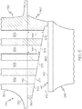
FIG. 5 is a partial cross-sectional view of theturbine rotor assembly 250 through line 5-5 ofFIG. 4 in accordance with an exemplary embodiment. In particular, and as introduced above,FIG. 5 depicts theattachment portion 360 of theturbine rotor blade 260 mounted inslot 410 of therotor disk 280. As also discussed above, theslot bottom 416 andbase surface 370 define theslot cavity 450 to receive cooling air through thecavity inlet 452 and to direct the cooling air into the feed inlets 372-375 formed in thebase surface 370, which in turn, direct the cooling air throughfluid passages attachment portion 360,platform 350, andairfoil 310. - During operation, it is generally advantageous to provide optimum flow characteristics for the cooling air flowing through the
slot cavity 450 and into the feed inlets 372-375. These flow characteristics typically include the avoidance of vortices, uneven pressure distributions, and uneven flow distributions. As an example, it is generally desirable to provide even flow distributions to each of the feed inlets 372-375, while minimizing pressure losses through theslot cavity 450 and at the feed inlets 372-375. In other examples, it may be desirable to provide predetermined, different amounts of flow and pressure to the individual feed inlets 372-375. - As described in greater detail below, the
attachment portion 360 is sized and shaped to provide advantageous flow characteristics. In one exemplary embodiment, theslot bottom 416 is generally flat and theslot side walls attachment portion 360 such that thebase surface 370 is non-parallel to theside walls slot cavity 450, and thus, the flow characteristics of the cooling air flowing therethrough. - As shown in the view of
FIG. 5 , the cross-sectional area of theslot cavity 450 decreases in area along the axial direction. The decrease in cross-sectional area is a result of increase in depth (or length) of theattachment portion 360 such that thebase surface 370 is slanted radially inward. Although thebase surface 370 is interrupted by the feed inlets 372-375 in the particular view ofFIG. 5 , the general position and shape of thebase surface 370 is depicted in these areas with a dashed line. As shown, thebase surface 370 is generally slanted at a relatively constant angle. In other words, the depth of theattachment portion 360 increases linearly. In some embodiments, the improvements in the flow characteristics through theslot cavity 450 enable the elimination of flow structures along theslot bottom 416 and/or metering plates at the inlet feeds 372-375. - The depth of the
attachment portion 360 may be defined in any suitable manner such that the position of thebase surface 370 results in a decrease in cross-sectional area of theslot cavity 450.Exemplary depths FIG. 5 as the respective radial distance from the boundary between theplatform 350 and the attachment portion 360 (referenced by line 510) to thebase surface 370.Depth 550 is the length or depth of theattachment portion 360 proximate to thecavity inlet 452 and/or the forward end of thebase surface 370.Depth 552 is the length or depth of theattachment portion 360 proximate to thefeed inlet 374.Depth 554 is the length or depth of theattachment portion 360 proximate to thefeed inlet 375. As shown,depth 554 is greater thandepth 552, which in turn is greater thandepth 550. Typically, the overall depth decreases between the forward end and aft end of thebase surface 370. Generally, the depth decrease may be dependent on the characteristics of the cooling scheme and the overall flow delivery system design. Although the term "depth" is used herein, this parameter may inversely be referred to as distance from an engine centerline. - The increase in depth of the
attachment portion 360 and corresponding decrease in cross-sectional area functions to reduce undesired flow structures, such as vortices, particularly mid-channel vortices and aft-channel vortices. Reducing such vortices decreases uneven and detrimental pressure distributions, thereby leading to improved flow delivery to the feed inlets 372-375 and uniform pressure distributions and blade flow control. Computational fluid dynamic (CFD) analysis may be used to optimize the location and orientation of thebase surface 370. - The length of the
attachment portion 360 and corresponding shape and orientation of thebase surface 370 shown inFIG. 5 is one exemplary embodiment for decreasing the cross-sectional shape of theslot cavity 450.FIGS. 6-15 depict additional embodiments for decreasing the cross-sectional shape of the slot cavity. Any number of factors may be considered to determine the cross-sectional shape of the slot cavity, including blade weight, flow characteristics, stress and wear considerations, and the like. Additionally, the cross-sectional shapes discussed below may be used in lieu of or in conjunction with other blade and slot cavity features, including modifications for individual feed inlets. For example, generally, the feed inlets discussed below in each embodiment have the same general shape to the other feed inlets of the respective embodiments, albeit with at different depths. However, as introduced above, one or more feed inlets of a particular embodiment may have a different shape or configuration from the other feed inlets of that embodiment. -
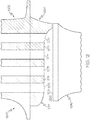
FIG. 6 is a partial cross-sectional view of aturbine rotor assembly 600 in accordance with an exemplary embodiment. Generally, the view of theturbine rotor assembly 600 corresponds to the view of theturbine rotor assembly 250 ofFIG. 5 . Unless otherwise noted, the discussion ofturbine rotor assembly 250 ofFIG. 5 is also applicable to theturbine rotor assembly 600 ofFIG. 6 . Theturbine rotor assembly 600 may be incorporated into the turbine section of the gas turbine engines discussed above. - As above, the
turbine rotor assembly 600 includes aturbine rotor blade 602 with anattachment portion 660 mounted in aslot 610 of arotor disk 680 to form aslot cavity 650 between abase surface 670 and aslot bottom 616. In this exemplary embodiment, feedinlets base surface 670 is stepped with flat (or axial) segments (or fillets) at various depths. In effect, the feed inlets 672-675 may be considered to be scoop inlets. As above, the depth of thebase surface 670 increases along the axial length of theslot cavity 650, thereby decreasing the cross-sectional area of theslot cavity 650 and enhancing flow characteristics. Additionally, in this exemplary embodiment, each feed inlet 672-675 may increase in depth along the axial length of the respective inlet 672-675, as indicated by the dashed line spanning each inlet 672-675. -
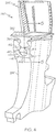
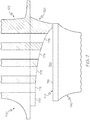
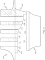
FIG. 7 is a partial cross-sectional view of aturbine rotor assembly 700 in accordance with an exemplary embodiment. Generally, the view of theturbine rotor assembly 700 corresponds to the view of theturbine rotor assembly 250 ofFIG. 5 . Unless otherwise noted, the discussion ofturbine rotor assembly 250 ofFIG. 5 is also applicable to theturbine rotor assembly 700 ofFIG. 7 . Theturbine rotor assembly 700 may be incorporated into the turbine section of the gas turbine engines discussed above. - As above, the
turbine rotor assembly 700 includes aturbine rotor blade 702 with anattachment portion 760 mounted in aslot 710 of arotor disk 780 to form aslot cavity 750 between abase surface 770 and aslot bottom 716.Feed inlets base surface 770. Additionally, in this exemplary embodiment, thebase surface 770 has a generally concave shape. As above, the depth of thebase surface 770 increases along the axial length of theslot cavity 750, thereby decreasing the cross-sectional area of theslot cavity 750 and enhancing flow characteristics. -
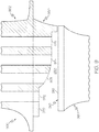
FIG. 8 is a partial cross-sectional view of aturbine rotor assembly 800 in accordance with an exemplary embodiment. Generally, the view of theturbine rotor assembly 800 corresponds to the view of theturbine rotor assembly 250 ofFIG. 5 . Unless otherwise noted, the discussion ofturbine rotor assembly 250 ofFIG. 5 is also applicable to theturbine rotor assembly 800 ofFIG. 8 . Theturbine rotor assembly 800 may be incorporated into the turbine section of the gas turbine engines discussed above. - As above, the
turbine rotor assembly 800 includes aturbine rotor blade 802 with an attachment portion 860 mounted in aslot 810 of arotor disk 880 to form aslot cavity 850 between abase surface 870 and aslot bottom 816.Feed inlets base surface 870. Additionally, in this exemplary embodiment, thebase surface 870 has a generally convex shape. As above, the depth of thebase surface 870 increases along the axial length of theslot cavity 850, thereby decreasing the cross-sectional area of theslot cavity 850 and enhancing flow characteristics. -
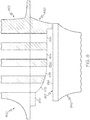
FIG. 9 is a partial cross-sectional view of aturbine rotor assembly 900 in accordance with an exemplary embodiment. Generally, the view of theturbine rotor assembly 900 corresponds to the view of theturbine rotor assembly 250 ofFIG. 5 . Unless otherwise noted, the discussion ofturbine rotor assembly 250 ofFIG. 5 is also applicable to theturbine rotor assembly 900 ofFIG. 9 . Theturbine rotor assembly 900 may be incorporated into the turbine section of the gas turbine engines discussed above. - As above, the
turbine rotor assembly 900 includes aturbine rotor blade 902 with anattachment portion 960 mounted in aslot 910 of arotor disk 980 to form a slot cavity 950 between abase surface 970 and aslot bottom 916.Feed inlets base surface 970. Additionally, in this exemplary embodiment, thebase surface 970 has a first segment 976 that is generally flat and a second segment 977 downstream of the first segment 976 that is generally convex. As above, the depth of thebase surface 970 increases along the axial length of the slot cavity 950, thereby decreasing the cross-sectional area of the slot cavity 950 and enhancing flow characteristics. -
FIG. 10 is a partial cross-sectional view of aturbine rotor assembly 1000 in accordance with an exemplary embodiment. Generally, the view of theturbine rotor assembly 1000 corresponds to the view of theturbine rotor assembly 250 ofFIG. 5 . Unless otherwise noted, the discussion ofturbine rotor assembly 250 ofFIG. 5 is also applicable to theturbine rotor assembly 1000 ofFIG. 10 . Theturbine rotor assembly 1000 may be incorporated into the turbine section of the gas turbine engines discussed above. - As above, the
turbine rotor assembly 1000 includes aturbine rotor blade 1002 with anattachment portion 1060 mounted in a slot 1010 of arotor disk 1080 to form aslot cavity 1050 between abase surface 1070 and aslot bottom 1016.Feed inlets base surface 1070. Additionally, in this exemplary embodiment, thebase surface 1070 has afirst segment 1076, asecond segment 1077, athird segment 1078, and afourth segment 1079, each of which are angled at different slopes. As above, the depth of thebase surface 1070 increases along the axial length of theslot cavity 1050, thereby decreasing the cross-sectional area of theslot cavity 1050 and enhancing flow characteristics. -
FIG. 11 is a partial cross-sectional view of aturbine rotor assembly 1100 in accordance with an exemplary embodiment. Generally, the view of theturbine rotor assembly 1100 corresponds to the view of theturbine rotor assembly 250 ofFIG. 5 . Unless otherwise noted, the discussion ofturbine rotor assembly 250 ofFIG. 5 is also applicable to theturbine rotor assembly 1100 ofFIG. 11 . Theturbine rotor assembly 1100 may be incorporated into the turbine section of the gas turbine engines discussed above. - As above, the
turbine rotor assembly 1100 includes aturbine rotor blade 1102 with anattachment portion 1160 mounted in a slot 1110 of arotor disk 1180 to form aslot cavity 1150 between abase surface 1170 and aslot bottom 1116.Feed inlets base surface 1170. Additionally, in this exemplary embodiment, thebase surface 1170 has afirst segment 1176, asecond segment 1177, and athird segment 1178. In this embodiment, the first andsecond segments third segment 1178 is convex, thereby resulting in abase surface 1170 with a combination of angled and convex shaped segments. As above, the depth of thebase surface 1170 increases along the axial length of theslot cavity 1150, thereby decreasing the cross-sectional area of theslot cavity 1150 and enhancing flow characteristics. -
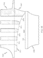
FIG. 12 is a partial cross-sectional view of aturbine rotor assembly 1200 in accordance with an exemplary embodiment. Generally, the view of theturbine rotor assembly 1200 corresponds to the view of theturbine rotor assembly 250 ofFIG. 5 . Unless otherwise noted, the discussion ofturbine rotor assembly 250 ofFIG. 5 is also applicable to theturbine rotor assembly 1200 ofFIG. 12 . Theturbine rotor assembly 1200 may be incorporated into the turbine section of the gas turbine engines discussed above. - As above, the
turbine rotor assembly 1200 includes aturbine rotor blade 1202 with anattachment portion 1260 mounted in a slot 1210 of arotor disk 1280 to form aslot cavity 1250 between abase surface 1270 and aslot bottom 1216.Feed inlets base surface 1270. Additionally, in this exemplary embodiment, thebase surface 1270 has afirst segment 1276 and asecond segment 1277. In this embodiment, thefirst segment 1276 is convex and thesecond segment 1277 is concave, thereby resulting in abase surface 1270 with a combination of convex and concave shaped segments. As above, the depth of thebase surface 1270 increases along the axial length of theslot cavity 1250, thereby decreasing the cross-sectional area of theslot cavity 1250 and enhancing flow characteristics. -
FIG. 13 is a partial cross-sectional view of aturbine rotor assembly 1300 in accordance with an exemplary embodiment. Generally, the view of theturbine rotor assembly 1300 corresponds to the view of theturbine rotor assembly 250 ofFIG. 5 . Unless otherwise noted, the discussion ofturbine rotor assembly 250 ofFIG. 5 is also applicable to theturbine rotor assembly 1300 ofFIG. 13 . Theturbine rotor assembly 1300 may be incorporated into the turbine section of the gas turbine engines discussed above. - As above, the
turbine rotor assembly 1300 includes aturbine rotor blade 1302 with anattachment portion 1360 mounted in a slot 1310 of arotor disk 1380 to form aslot cavity 1350 between abase surface 1370 and aslot bottom 1316.Feed inlets base surface 1370. In this exemplary embodiment, thebase surface 1370 has a generally curved shape with an increasing depth, thereby decreasing the cross-sectional area of theslot cavity 1350 and enhancing flow characteristics. Additionally, in this embodiment, each of thefeed inlets feed inlet -
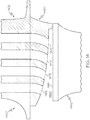
FIG. 14 is a partial cross-sectional view of aturbine rotor assembly 1400 in accordance with an exemplary embodiment. Generally, the view of theturbine rotor assembly 1400 corresponds to the view of theturbine rotor assembly 250 ofFIG. 5 . Unless otherwise noted, the discussion ofturbine rotor assembly 250 ofFIG. 5 is also applicable to theturbine rotor assembly 1400 ofFIG. 14 . Theturbine rotor assembly 1400 may be incorporated into the turbine section of the gas turbine engines discussed above. - As above, the
turbine rotor assembly 1400 includes aturbine rotor blade 1402 with anattachment portion 1460 mounted in a slot 1410 of arotor disk 1480 to form aslot cavity 1450 between a base surface 1470 and aslot bottom 1416.Feed inlets slot cavity 1450 and enhancing flow characteristics. Additionally, in this embodiment, each of thefeed inlets feed inlet -
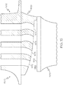
FIG. 15 is a partial cross-sectional view of aturbine rotor assembly 1500 in accordance with an exemplary embodiment. Generally, the view of theturbine rotor assembly 1500 corresponds to the view of theturbine rotor assembly 250 ofFIG. 5 . Unless otherwise noted, the discussion ofturbine rotor assembly 250 ofFIG. 5 is also applicable to theturbine rotor assembly 1500 ofFIG. 15 . Theturbine rotor assembly 1500 may be incorporated into the turbine section of the gas turbine engines discussed above. - As above, the
turbine rotor assembly 1500 includes aturbine rotor blade 1502 with anattachment portion 1560 mounted in a slot 1510 of arotor disk 1580 to form aslot cavity 1550 between a base surface 1570 and aslot bottom 1516.Feed inlets slot cavity 1550 and enhancing flow characteristics. Additionally, in this embodiment, each of thefeed inlets feed inlet feed inlets feed inlets -
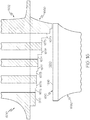
FIG. 16 is a partial cross-sectional view of aturbine rotor assembly 1600 in accordance with an exemplary embodiment. Generally, the view of theturbine rotor assembly 1600 corresponds to the view of theturbine rotor assembly 250 ofFIG. 5 . Unless otherwise noted, the discussion ofturbine rotor assembly 250 ofFIG. 5 is also applicable to theturbine rotor assembly 1600 ofFIG. 16 . Theturbine rotor assembly 1600 may be incorporated into the turbine section of the gas turbine engines discussed above. - As above, the
turbine rotor assembly 1600 includes aturbine rotor blade 1602 with anattachment portion 1660 mounted in aslot 1610 of arotor disk 1680 to form aslot cavity 1650 between a base surface 1670 and aslot bottom 1616.Feed inlets steps inlet slot cavity 1650, thereby decreasing the cross-sectional area of theslot cavity 1650 and enhancing flow characteristics. - Although the
turbine rotor assemblies FIGS. 5-16 are discussed as a single or integral component, in other embodiments, theturbine rotor assemblies - The exemplary embodiments discussed above may be manufactured in any suitable way. As one example,
FIG. 17 is a flow chart of amethod 1700 for forming a turbine rotor assembly (e.g.,turbine rotor assemblies FIGS. 5-16 ) in accordance with an exemplary embodiment. - In a
first step 1710, a baseline turbine rotor assembly is considered, for example, with CFD analysis to evaluate flow characteristics. Generally, such turbine rotor assemblies correspond to the turbine rotor assemblies discussed above in which turbine rotor blades are mounted on a rotor disk in a turbine section. As above, each turbine rotor blade forms a slot cavity with the rotor disk to direct air through the slot cavity and into inlet feeds for cooling. In general, the baseline turbine rotor assembly may include a rotor blade with a flattened bottom surface such that a slot cavity with a generally constant cross-sectional area is formed. - In a second step 1720, the attachment portion and base surface of the turbine rotor blade are modified and reevaluated in view of the resulting flow characteristics. In one exemplary embodiment and as discussed above, the attachment portion and base surface are generally modified such that the cross-sectional area of the slot cavity decreases in an axial direction. Any suitable modifications and adjustments may be made, including a base surface with slanted or angled sections, curved sections, stepped sections, inlet curvatures, and the like, as discussed above. The base surface adjustments may be evaluated with CFD analysis until satisfactory flow characteristics are achieved.
- In a
third step 1730, the turbine rotor blade is formed. Any suitable manufacturing technique may be provided, including casting and additive manufacturing techniques. Typically, in this step, the turbine rotor blade is formed with a flat base surface. - In a
fourth step 1740, the attachment portion, and thus the base surface, of the turbine rotor blade is modified in accordance with the evaluation in the second step 1720. For example, the various slanted, curved, and inlet segments may be formed in the attachment portion to result in the desired base surface shape. The attachment portion may be modified with any suitable technique, including machining, grinding, wire EDM, and the like. In some embodiments,steps - In a
final step 1750, the turbine rotor blade is mounted onto the rotor disk with similar turbine rotor blades for assembly into the turbine section of a gas turbine engine. - As a result, the turbine assemblies and methods discussed above enable more efficient cooling and/or improved operation of gas turbine engines. Additionally, the improved cooling may enable a reduction in cooling air that may be used in other locations and/or redirected to mainstream gas flow. Exemplary embodiments discussed above have resulted in an ability to increase engine temperature, thereby improving fuel consumption. Exemplary embodiments promote the service life and/or enhanced performance in a cost-effective manner. The turbine assemblies produced according to exemplary embodiments may find beneficial use in many industries including aerospace, but also including industrial applications such as electricity generation, naval propulsion, pumping sets for gas and oil transmission, aircraft propulsion, automobile engines, and/or stationary power plants.
- While at least one exemplary embodiment has been presented in the foregoing detailed description of the inventive subject matter, it should be appreciated that a vast number of variations exist. It should also be appreciated that the exemplary embodiment or exemplary embodiments are only examples, and are not intended to limit the scope, applicability, or configuration of the inventive subject matter in any way. Rather, the foregoing detailed description will provide those skilled in the art with a convenient road map for implementing an exemplary embodiment of the inventive subject matter. It being understood that various changes may be made in the function and arrangement of elements described in an exemplary embodiment without departing from the scope of the inventive subject matter as set forth in the appended claims.
Claims (7)
- A turbine rotor blade (260, 602, 702, 802, 902, 1002, 1102, 1202, 1302, 1402, 1502, 1602), comprising:a platform (350) with a first side and a second side;an airfoil (310) extending from the first side of the platform (350), characterised in that it further comprises :an attachment portion (360, 660, 760, 860, 960, 1060, 1160, 1260, 1360, 1460, 1560, 1660) extending from the second side of the platform (350), wherein the attachment portion (360, 660, 760, 860, 960, 1060, 1160, 1260, 1360, 1460, 1560, 1660) includes first and second side surfaces and a base surface (370, 670, 770, 870, 970, 1070, 1170, 1270, 1370, 1470, 1570, 1670) on an underside of the attachment portion (360, 660, 760, 860, 960, 1060, 1160, 1260, 1360, 1460, 1560, 1660) between the first and second side surface, and wherein the base surface (370, 670, 770, 870, 970, 1070, 1170, 1270, 1370, 1470, 1570, 1670) includes at least one curved segment or angled segment, wherein the base surface (370, 670, 770, 870, 970, 1070, 1170, 1270, 1370, 1470, 1570, 1670) forms a slot cavity
(450,650,750,850,950,1050,1150,1250,1350,1450,1550,1650) with a flat slot bottom (416,616,816,916,1016,1116,1216,1316,1416,1516,1616) andfluid passages (572) with feed inlets (372-375, 472-475, 572-575, 672-675, 772-775, 872-875, 972-975, 1072-1075, 1172-1175, 1272-1275, 1372-1375, 1472-1475, 1572-1575, 1672-1675) defined in the base surface (370, 670, 770, 870, 970, 1070, 1170, 1270, 1370, 1470, 1570, 1670) in an axial row,wherein the base surface (370, 670, 770, 870, 970, 1070, 1170, 1270, 1370, 1470, 1570, 1670) is shaped such that the slot cavity (450, 650, 750, 850, 950, 1050, 1150, 1250, 1350, 1450, 1550, 1650) has a cross-sectional area that decreases along a generally axial direction from a forward end to an aft end, andwherein the feed inlets (372-375, 472-475,572-575, 572-575,672-675,772-775,872-875,972-975,1072-1075, 1172-1175, 1272-1275, 1372-1375,1472-1475,1572-1575,1672-1675)are positioned in the base surface
(370,670,770,870,970,1070,1170,1270,1370,1470,1570,1670) such that a radial depth of each feed inlet (372-375, 472-475, 572-575, 672-675, 772-775, 872-875, 972-975, 1072-1075, 1172-1175, 1272-1275, 1372-1375,1472-1475, 1572-1575, 1672-1675) increases along the generally axial direction. - The turbine rotor blade (702, 1202, 1302) of claim 1, wherein the base surface (770, 1270, 1370) includes at least one concave segment.
- The turbine rotor blade (802, 902, 1102, 1202, 1402, 1502) of claim 1, wherein the base surface (870, 970, 1170, 1270, 1470, 1570) includes at least one convex segment.
- The turbine rotor blade (1002) of claim 1, wherein the base surface (1070) includes a plurality of the angled segments, each with a different slope.
- The turbine rotor blade (1202) of claim 1, wherein the base surface (1270) includes at least one concave segment and at least one convex segment.
- The turbine rotor blade (902, 1102) of claim 1, wherein the base surface (970, 1170,) includes at least one curved segment and at least one angled segment.
- The turbine rotor blade (1402, 1502) of claim 6, wherein the feed inlets (1472-1475, 1572-1575) are scooped.
Applications Claiming Priority (1)
| Application Number | Priority Date | Filing Date | Title |
|---|---|---|---|
| US14/159,043 US9777575B2 (en) | 2014-01-20 | 2014-01-20 | Turbine rotor assemblies with improved slot cavities |
Publications (2)
| Publication Number | Publication Date |
|---|---|
| EP2896786A1 EP2896786A1 (en) | 2015-07-22 |
| EP2896786B1 true EP2896786B1 (en) | 2019-03-13 |
Family
ID=52347183
Family Applications (1)
| Application Number | Title | Priority Date | Filing Date |
|---|---|---|---|
| EP15151181.3A Active EP2896786B1 (en) | 2014-01-20 | 2015-01-14 | Turbine rotor assemblies with improved slot cavities |
Country Status (2)
| Country | Link |
|---|---|
| US (1) | US9777575B2 (en) |
| EP (1) | EP2896786B1 (en) |
Families Citing this family (7)
| Publication number | Priority date | Publication date | Assignee | Title |
|---|---|---|---|---|
| FR3043133B1 (en) * | 2015-10-30 | 2020-09-18 | Turbomeca | TURBOMACHINE VANE CONSISTING OF A FLOOR FOOT AND CROSSES BY COOLING AIR CAVITIES |
| US10047611B2 (en) | 2016-01-28 | 2018-08-14 | United Technologies Corporation | Turbine blade attachment curved rib stiffeners |
| US10683763B2 (en) | 2016-10-04 | 2020-06-16 | Honeywell International Inc. | Turbine blade with integral flow meter |
| US10648354B2 (en) * | 2016-12-02 | 2020-05-12 | Honeywell International Inc. | Turbine wheels, turbine engines including the same, and methods of forming turbine wheels with improved seal plate sealing |
| KR101984397B1 (en) * | 2017-09-29 | 2019-05-30 | 두산중공업 주식회사 | Rotor, turbine and gas turbine comprising the same |
| FR3087479B1 (en) | 2018-10-23 | 2022-05-13 | Safran Aircraft Engines | DAWN OF TURBOMACHINE |
| CN115111000A (en) * | 2022-07-08 | 2022-09-27 | 景德镇明兴航空锻压有限公司 | Aeroengine turbine blade with cooling function |
Family Cites Families (22)
| Publication number | Priority date | Publication date | Assignee | Title |
|---|---|---|---|---|
| NL88170C (en) * | 1952-10-31 | 1900-01-01 | ||
| US2848193A (en) | 1953-04-08 | 1958-08-19 | Gen Electric | Air cooled turbomachine blading |
| BE530261A (en) | 1953-07-11 | |||
| GB853586A (en) | 1957-06-15 | 1960-11-09 | Rolls Royce | Improved turbine blades, compressor blades and method of manufacturing the same |
| DE1173732B (en) | 1960-06-08 | 1964-07-09 | Gen Motors Corp | Cast turbine blade |
| NL300988A (en) | 1963-10-29 | |||
| GB1350471A (en) * | 1971-05-06 | 1974-04-18 | Secr Defence | Gas turbine engine |
| FR2485632B1 (en) | 1980-06-30 | 1985-07-05 | Snecma | IMPROVEMENT IN VENTILATION SYSTEMS OF BLADES AND TURBINE DISCS |
| USRE33954E (en) * | 1982-02-22 | 1992-06-09 | United Technologies Corporation | Rotor blade assembly |
| US4451205A (en) * | 1982-02-22 | 1984-05-29 | United Technologies Corporation | Rotor blade assembly |
| JPS59108805A (en) | 1982-12-15 | 1984-06-23 | Toshiba Corp | Turbine moving blade fixing device |
| US4820126A (en) | 1988-02-22 | 1989-04-11 | Westinghouse Electric Corp. | Turbomachine rotor assembly having reduced stress concentrations |
| US5403156A (en) | 1993-10-26 | 1995-04-04 | United Technologies Corporation | Integral meter plate for turbine blade and method |
| EP1041246A1 (en) | 1999-03-29 | 2000-10-04 | Siemens Aktiengesellschaft | Casted gas turbine blade with inner cooling, method and device for manufacturing a manifold of the gas turbine blade |
| EP1136654A1 (en) | 2000-03-21 | 2001-09-26 | Siemens Aktiengesellschaft | Turbine rotor blade |
| US6786696B2 (en) | 2002-05-06 | 2004-09-07 | General Electric Company | Root notched turbine blade |
| US6932570B2 (en) | 2002-05-23 | 2005-08-23 | General Electric Company | Methods and apparatus for extending gas turbine engine airfoils useful life |
| US7442007B2 (en) * | 2005-06-02 | 2008-10-28 | Pratt & Whitney Canada Corp. | Angled blade firtree retaining system |
| EP2090751A1 (en) | 2008-02-15 | 2009-08-19 | Siemens Aktiengesellschaft | Rotor blade for a turbo engine |
| JP5379585B2 (en) | 2009-07-15 | 2013-12-25 | 株式会社日立製作所 | Steam turbine with cleaning function for blade mounting part |
| US8622702B1 (en) * | 2010-04-21 | 2014-01-07 | Florida Turbine Technologies, Inc. | Turbine blade with cooling air inlet holes |
| US8939711B2 (en) * | 2013-02-15 | 2015-01-27 | Siemens Aktiengesellschaft | Outer rim seal assembly in a turbine engine |
-
2014
- 2014-01-20 US US14/159,043 patent/US9777575B2/en active Active
-
2015
- 2015-01-14 EP EP15151181.3A patent/EP2896786B1/en active Active
Non-Patent Citations (1)
| Title |
|---|
| None * |
Also Published As
| Publication number | Publication date |
|---|---|
| US9777575B2 (en) | 2017-10-03 |
| EP2896786A1 (en) | 2015-07-22 |
| US20150204194A1 (en) | 2015-07-23 |
Similar Documents
| Publication | Publication Date | Title |
|---|---|---|
| US10934856B2 (en) | Gas turbine engines with improved leading edge airfoil cooling | |
| EP2787174B1 (en) | Gas turbine engines with turbine airfoil cooling | |
| US9546554B2 (en) | Gas turbine engine components with blade tip cooling | |
| EP2896786B1 (en) | Turbine rotor assemblies with improved slot cavities | |
| EP2716866B1 (en) | Gas turbine engine components with lateral and forward sweep film cooling holes | |
| US9879544B2 (en) | Turbine rotor blades with improved tip portion cooling holes | |
| EP2851511A2 (en) | Turbine blades with tip portions having converging cooling holes | |
| US20100310353A1 (en) | Rotor casing treatment with recessed baffles | |
| EP2388435A2 (en) | Turbine blade with cooled platform | |
| CN106907181B (en) | Internal Cooling Configurations in Turbine Rotor Blades | |
| US11199099B2 (en) | Gas turbine engines with improved airfoil dust removal | |
| EP2634370B1 (en) | Turbine bucket with a core cavity having a contoured turn | |
| US9816389B2 (en) | Turbine rotor blades with tip portion parapet wall cavities | |
| EP2848769B1 (en) | Method of producing a turbine rotor blade | |
| EP2971545B1 (en) | Low pressure loss cooled blade | |
| US20160186577A1 (en) | Cooling configurations for turbine blades |
Legal Events
| Date | Code | Title | Description |
|---|---|---|---|
| PUAI | Public reference made under article 153(3) epc to a published international application that has entered the european phase |
Free format text: ORIGINAL CODE: 0009012 |
|
| 17P | Request for examination filed |
Effective date: 20150114 |
|
| AK | Designated contracting states |
Kind code of ref document: A1 Designated state(s): AL AT BE BG CH CY CZ DE DK EE ES FI FR GB GR HR HU IE IS IT LI LT LU LV MC MK MT NL NO PL PT RO RS SE SI SK SM TR |
|
| AX | Request for extension of the european patent |
Extension state: BA ME |
|
| RAP1 | Party data changed (applicant data changed or rights of an application transferred) |
Owner name: HONEYWELL INTERNATIONAL INC. |
|
| REG | Reference to a national code |
Ref country code: DE Ref legal event code: R079 Ref document number: 602015026152 Country of ref document: DE Free format text: PREVIOUS MAIN CLASS: F01D0005080000 Ipc: F01D0005040000 |
|
| RIC1 | Information provided on ipc code assigned before grant |
Ipc: F01D 5/18 20060101ALI20180627BHEP Ipc: F01D 5/08 20060101ALI20180627BHEP Ipc: F01D 5/30 20060101ALI20180627BHEP Ipc: F01D 5/04 20060101AFI20180627BHEP |
|
| GRAP | Despatch of communication of intention to grant a patent |
Free format text: ORIGINAL CODE: EPIDOSNIGR1 |
|
| STAA | Information on the status of an ep patent application or granted ep patent |
Free format text: STATUS: GRANT OF PATENT IS INTENDED |
|
| INTG | Intention to grant announced |
Effective date: 20180806 |
|
| RIN1 | Information on inventor provided before grant (corrected) |
Inventor name: HARMAN, STUART ANDREW Inventor name: HALFMANN, STEVE Inventor name: TAPIA, LUIS |
|
| GRAS | Grant fee paid |
Free format text: ORIGINAL CODE: EPIDOSNIGR3 |
|
| GRAA | (expected) grant |
Free format text: ORIGINAL CODE: 0009210 |
|
| STAA | Information on the status of an ep patent application or granted ep patent |
Free format text: STATUS: THE PATENT HAS BEEN GRANTED |
|
| AK | Designated contracting states |
Kind code of ref document: B1 Designated state(s): AL AT BE BG CH CY CZ DE DK EE ES FI FR GB GR HR HU IE IS IT LI LT LU LV MC MK MT NL NO PL PT RO RS SE SI SK SM TR |
|
| REG | Reference to a national code |
Ref country code: GB Ref legal event code: FG4D |
|
| REG | Reference to a national code |
Ref country code: AT Ref legal event code: REF Ref document number: 1107930 Country of ref document: AT Kind code of ref document: T Effective date: 20190315 Ref country code: CH Ref legal event code: EP |
|
| REG | Reference to a national code |
Ref country code: IE Ref legal event code: FG4D |
|
| REG | Reference to a national code |
Ref country code: DE Ref legal event code: R096 Ref document number: 602015026152 Country of ref document: DE |
|
| REG | Reference to a national code |
Ref country code: NL Ref legal event code: MP Effective date: 20190313 |
|
| REG | Reference to a national code |
Ref country code: LT Ref legal event code: MG4D |
|
| PG25 | Lapsed in a contracting state [announced via postgrant information from national office to epo] |
Ref country code: LT Free format text: LAPSE BECAUSE OF FAILURE TO SUBMIT A TRANSLATION OF THE DESCRIPTION OR TO PAY THE FEE WITHIN THE PRESCRIBED TIME-LIMIT Effective date: 20190313 Ref country code: NO Free format text: LAPSE BECAUSE OF FAILURE TO SUBMIT A TRANSLATION OF THE DESCRIPTION OR TO PAY THE FEE WITHIN THE PRESCRIBED TIME-LIMIT Effective date: 20190613 Ref country code: FI Free format text: LAPSE BECAUSE OF FAILURE TO SUBMIT A TRANSLATION OF THE DESCRIPTION OR TO PAY THE FEE WITHIN THE PRESCRIBED TIME-LIMIT Effective date: 20190313 Ref country code: SE Free format text: LAPSE BECAUSE OF FAILURE TO SUBMIT A TRANSLATION OF THE DESCRIPTION OR TO PAY THE FEE WITHIN THE PRESCRIBED TIME-LIMIT Effective date: 20190313 |
|
| PG25 | Lapsed in a contracting state [announced via postgrant information from national office to epo] |
Ref country code: BG Free format text: LAPSE BECAUSE OF FAILURE TO SUBMIT A TRANSLATION OF THE DESCRIPTION OR TO PAY THE FEE WITHIN THE PRESCRIBED TIME-LIMIT Effective date: 20190613 Ref country code: NL Free format text: LAPSE BECAUSE OF FAILURE TO SUBMIT A TRANSLATION OF THE DESCRIPTION OR TO PAY THE FEE WITHIN THE PRESCRIBED TIME-LIMIT Effective date: 20190313 Ref country code: RS Free format text: LAPSE BECAUSE OF FAILURE TO SUBMIT A TRANSLATION OF THE DESCRIPTION OR TO PAY THE FEE WITHIN THE PRESCRIBED TIME-LIMIT Effective date: 20190313 Ref country code: LV Free format text: LAPSE BECAUSE OF FAILURE TO SUBMIT A TRANSLATION OF THE DESCRIPTION OR TO PAY THE FEE WITHIN THE PRESCRIBED TIME-LIMIT Effective date: 20190313 Ref country code: HR Free format text: LAPSE BECAUSE OF FAILURE TO SUBMIT A TRANSLATION OF THE DESCRIPTION OR TO PAY THE FEE WITHIN THE PRESCRIBED TIME-LIMIT Effective date: 20190313 Ref country code: GR Free format text: LAPSE BECAUSE OF FAILURE TO SUBMIT A TRANSLATION OF THE DESCRIPTION OR TO PAY THE FEE WITHIN THE PRESCRIBED TIME-LIMIT Effective date: 20190614 |
|
| REG | Reference to a national code |
Ref country code: AT Ref legal event code: MK05 Ref document number: 1107930 Country of ref document: AT Kind code of ref document: T Effective date: 20190313 |
|
| PG25 | Lapsed in a contracting state [announced via postgrant information from national office to epo] |
Ref country code: PT Free format text: LAPSE BECAUSE OF FAILURE TO SUBMIT A TRANSLATION OF THE DESCRIPTION OR TO PAY THE FEE WITHIN THE PRESCRIBED TIME-LIMIT Effective date: 20190713 Ref country code: AL Free format text: LAPSE BECAUSE OF FAILURE TO SUBMIT A TRANSLATION OF THE DESCRIPTION OR TO PAY THE FEE WITHIN THE PRESCRIBED TIME-LIMIT Effective date: 20190313 Ref country code: SK Free format text: LAPSE BECAUSE OF FAILURE TO SUBMIT A TRANSLATION OF THE DESCRIPTION OR TO PAY THE FEE WITHIN THE PRESCRIBED TIME-LIMIT Effective date: 20190313 Ref country code: EE Free format text: LAPSE BECAUSE OF FAILURE TO SUBMIT A TRANSLATION OF THE DESCRIPTION OR TO PAY THE FEE WITHIN THE PRESCRIBED TIME-LIMIT Effective date: 20190313 Ref country code: RO Free format text: LAPSE BECAUSE OF FAILURE TO SUBMIT A TRANSLATION OF THE DESCRIPTION OR TO PAY THE FEE WITHIN THE PRESCRIBED TIME-LIMIT Effective date: 20190313 Ref country code: CZ Free format text: LAPSE BECAUSE OF FAILURE TO SUBMIT A TRANSLATION OF THE DESCRIPTION OR TO PAY THE FEE WITHIN THE PRESCRIBED TIME-LIMIT Effective date: 20190313 Ref country code: ES Free format text: LAPSE BECAUSE OF FAILURE TO SUBMIT A TRANSLATION OF THE DESCRIPTION OR TO PAY THE FEE WITHIN THE PRESCRIBED TIME-LIMIT Effective date: 20190313 Ref country code: IT Free format text: LAPSE BECAUSE OF FAILURE TO SUBMIT A TRANSLATION OF THE DESCRIPTION OR TO PAY THE FEE WITHIN THE PRESCRIBED TIME-LIMIT Effective date: 20190313 |
|
| PG25 | Lapsed in a contracting state [announced via postgrant information from national office to epo] |
Ref country code: SM Free format text: LAPSE BECAUSE OF FAILURE TO SUBMIT A TRANSLATION OF THE DESCRIPTION OR TO PAY THE FEE WITHIN THE PRESCRIBED TIME-LIMIT Effective date: 20190313 Ref country code: PL Free format text: LAPSE BECAUSE OF FAILURE TO SUBMIT A TRANSLATION OF THE DESCRIPTION OR TO PAY THE FEE WITHIN THE PRESCRIBED TIME-LIMIT Effective date: 20190313 |
|
| REG | Reference to a national code |
Ref country code: DE Ref legal event code: R097 Ref document number: 602015026152 Country of ref document: DE |
|
| PG25 | Lapsed in a contracting state [announced via postgrant information from national office to epo] |
Ref country code: IS Free format text: LAPSE BECAUSE OF FAILURE TO SUBMIT A TRANSLATION OF THE DESCRIPTION OR TO PAY THE FEE WITHIN THE PRESCRIBED TIME-LIMIT Effective date: 20190713 Ref country code: AT Free format text: LAPSE BECAUSE OF FAILURE TO SUBMIT A TRANSLATION OF THE DESCRIPTION OR TO PAY THE FEE WITHIN THE PRESCRIBED TIME-LIMIT Effective date: 20190313 |
|
| PLBE | No opposition filed within time limit |
Free format text: ORIGINAL CODE: 0009261 |
|
| STAA | Information on the status of an ep patent application or granted ep patent |
Free format text: STATUS: NO OPPOSITION FILED WITHIN TIME LIMIT |
|
| PG25 | Lapsed in a contracting state [announced via postgrant information from national office to epo] |
Ref country code: DK Free format text: LAPSE BECAUSE OF FAILURE TO SUBMIT A TRANSLATION OF THE DESCRIPTION OR TO PAY THE FEE WITHIN THE PRESCRIBED TIME-LIMIT Effective date: 20190313 |
|
| 26N | No opposition filed |
Effective date: 20191216 |
|
| PG25 | Lapsed in a contracting state [announced via postgrant information from national office to epo] |
Ref country code: SI Free format text: LAPSE BECAUSE OF FAILURE TO SUBMIT A TRANSLATION OF THE DESCRIPTION OR TO PAY THE FEE WITHIN THE PRESCRIBED TIME-LIMIT Effective date: 20190313 |
|
| PG25 | Lapsed in a contracting state [announced via postgrant information from national office to epo] |
Ref country code: TR Free format text: LAPSE BECAUSE OF FAILURE TO SUBMIT A TRANSLATION OF THE DESCRIPTION OR TO PAY THE FEE WITHIN THE PRESCRIBED TIME-LIMIT Effective date: 20190313 |
|
| PGFP | Annual fee paid to national office [announced via postgrant information from national office to epo] |
Ref country code: DE Payment date: 20200131 Year of fee payment: 6 |
|
| PG25 | Lapsed in a contracting state [announced via postgrant information from national office to epo] |
Ref country code: MC Free format text: LAPSE BECAUSE OF FAILURE TO SUBMIT A TRANSLATION OF THE DESCRIPTION OR TO PAY THE FEE WITHIN THE PRESCRIBED TIME-LIMIT Effective date: 20190313 |
|
| REG | Reference to a national code |
Ref country code: CH Ref legal event code: PL |
|
| GBPC | Gb: european patent ceased through non-payment of renewal fee |
Effective date: 20200114 |
|
| REG | Reference to a national code |
Ref country code: BE Ref legal event code: MM Effective date: 20200131 |
|
| PG25 | Lapsed in a contracting state [announced via postgrant information from national office to epo] |
Ref country code: LU Free format text: LAPSE BECAUSE OF NON-PAYMENT OF DUE FEES Effective date: 20200114 Ref country code: GB Free format text: LAPSE BECAUSE OF NON-PAYMENT OF DUE FEES Effective date: 20200114 Ref country code: FR Free format text: LAPSE BECAUSE OF NON-PAYMENT OF DUE FEES Effective date: 20200131 |
|
| PG25 | Lapsed in a contracting state [announced via postgrant information from national office to epo] |
Ref country code: CH Free format text: LAPSE BECAUSE OF NON-PAYMENT OF DUE FEES Effective date: 20200131 Ref country code: BE Free format text: LAPSE BECAUSE OF NON-PAYMENT OF DUE FEES Effective date: 20200131 Ref country code: LI Free format text: LAPSE BECAUSE OF NON-PAYMENT OF DUE FEES Effective date: 20200131 |
|
| PG25 | Lapsed in a contracting state [announced via postgrant information from national office to epo] |
Ref country code: IE Free format text: LAPSE BECAUSE OF NON-PAYMENT OF DUE FEES Effective date: 20200114 |
|
| REG | Reference to a national code |
Ref country code: DE Ref legal event code: R119 Ref document number: 602015026152 Country of ref document: DE |
|
| PG25 | Lapsed in a contracting state [announced via postgrant information from national office to epo] |
Ref country code: DE Free format text: LAPSE BECAUSE OF NON-PAYMENT OF DUE FEES Effective date: 20210803 |
|
| PG25 | Lapsed in a contracting state [announced via postgrant information from national office to epo] |
Ref country code: MT Free format text: LAPSE BECAUSE OF FAILURE TO SUBMIT A TRANSLATION OF THE DESCRIPTION OR TO PAY THE FEE WITHIN THE PRESCRIBED TIME-LIMIT Effective date: 20190313 Ref country code: CY Free format text: LAPSE BECAUSE OF FAILURE TO SUBMIT A TRANSLATION OF THE DESCRIPTION OR TO PAY THE FEE WITHIN THE PRESCRIBED TIME-LIMIT Effective date: 20190313 |
|
| PG25 | Lapsed in a contracting state [announced via postgrant information from national office to epo] |
Ref country code: MK Free format text: LAPSE BECAUSE OF FAILURE TO SUBMIT A TRANSLATION OF THE DESCRIPTION OR TO PAY THE FEE WITHIN THE PRESCRIBED TIME-LIMIT Effective date: 20190313 |
|
| P01 | Opt-out of the competence of the unified patent court (upc) registered |
Effective date: 20230525 |