EP2896586B1 - Inertia braking payout device and package system - Google Patents
Inertia braking payout device and package system Download PDFInfo
- Publication number
- EP2896586B1 EP2896586B1 EP15150979.1A EP15150979A EP2896586B1 EP 2896586 B1 EP2896586 B1 EP 2896586B1 EP 15150979 A EP15150979 A EP 15150979A EP 2896586 B1 EP2896586 B1 EP 2896586B1
- Authority
- EP
- European Patent Office
- Prior art keywords
- carton
- rotatable member
- diameter end
- slot
- interior compartment
- Prior art date
- Legal status (The legal status is an assumption and is not a legal conclusion. Google has not performed a legal analysis and makes no representation as to the accuracy of the status listed.)
- Active
Links
- 239000000463 material Substances 0.000 claims description 65
- 238000005520 cutting process Methods 0.000 claims description 3
- 239000011096 corrugated fiberboard Substances 0.000 claims description 2
- 239000002985 plastic film Substances 0.000 claims description 2
- 229920006255 plastic film Polymers 0.000 claims description 2
- 230000005484 gravity Effects 0.000 description 3
- 238000004806 packaging method and process Methods 0.000 description 3
- 238000000034 method Methods 0.000 description 2
- 238000012856 packing Methods 0.000 description 2
- 239000004033 plastic Substances 0.000 description 2
- -1 ribbon Substances 0.000 description 2
- 239000003086 colorant Substances 0.000 description 1
- 239000000428 dust Substances 0.000 description 1
- 239000004744 fabric Substances 0.000 description 1
- 239000011152 fibreglass Substances 0.000 description 1
- 238000005304 joining Methods 0.000 description 1
- 238000004519 manufacturing process Methods 0.000 description 1
- 238000012986 modification Methods 0.000 description 1
- 230000004048 modification Effects 0.000 description 1
- 239000002699 waste material Substances 0.000 description 1
Images


Classifications
-
- B—PERFORMING OPERATIONS; TRANSPORTING
- B65—CONVEYING; PACKING; STORING; HANDLING THIN OR FILAMENTARY MATERIAL
- B65H—HANDLING THIN OR FILAMENTARY MATERIAL, e.g. SHEETS, WEBS, CABLES
- B65H49/00—Unwinding or paying-out filamentary material; Supporting, storing or transporting packages from which filamentary material is to be withdrawn or paid-out
- B65H49/18—Methods or apparatus in which packages rotate
- B65H49/20—Package-supporting devices
- B65H49/205—Hand-held or portable dispensers
-
- B—PERFORMING OPERATIONS; TRANSPORTING
- B65—CONVEYING; PACKING; STORING; HANDLING THIN OR FILAMENTARY MATERIAL
- B65H—HANDLING THIN OR FILAMENTARY MATERIAL, e.g. SHEETS, WEBS, CABLES
- B65H49/00—Unwinding or paying-out filamentary material; Supporting, storing or transporting packages from which filamentary material is to be withdrawn or paid-out
- B65H49/18—Methods or apparatus in which packages rotate
- B65H49/20—Package-supporting devices
- B65H49/32—Stands or frameworks
- B65H49/322—Enclosing boxes with supporting means for the package or reel during unwinding
-
- B—PERFORMING OPERATIONS; TRANSPORTING
- B65—CONVEYING; PACKING; STORING; HANDLING THIN OR FILAMENTARY MATERIAL
- B65H—HANDLING THIN OR FILAMENTARY MATERIAL, e.g. SHEETS, WEBS, CABLES
- B65H2301/00—Handling processes for sheets or webs
- B65H2301/50—Auxiliary process performed during handling process
- B65H2301/51—Modifying a characteristic of handled material
- B65H2301/515—Cutting handled material
- B65H2301/5154—Cutting handled material from hand-held or table dispenser
-
- B—PERFORMING OPERATIONS; TRANSPORTING
- B65—CONVEYING; PACKING; STORING; HANDLING THIN OR FILAMENTARY MATERIAL
- B65H—HANDLING THIN OR FILAMENTARY MATERIAL, e.g. SHEETS, WEBS, CABLES
- B65H2701/00—Handled material; Storage means
- B65H2701/30—Handled filamentary material
- B65H2701/33—Hollow or hose-like material
-
- B—PERFORMING OPERATIONS; TRANSPORTING
- B65—CONVEYING; PACKING; STORING; HANDLING THIN OR FILAMENTARY MATERIAL
- B65H—HANDLING THIN OR FILAMENTARY MATERIAL, e.g. SHEETS, WEBS, CABLES
- B65H2701/00—Handled material; Storage means
- B65H2701/30—Handled filamentary material
- B65H2701/35—Ropes, lines
-
- B—PERFORMING OPERATIONS; TRANSPORTING
- B65—CONVEYING; PACKING; STORING; HANDLING THIN OR FILAMENTARY MATERIAL
- B65H—HANDLING THIN OR FILAMENTARY MATERIAL, e.g. SHEETS, WEBS, CABLES
- B65H2701/00—Handled material; Storage means
- B65H2701/30—Handled filamentary material
- B65H2701/36—Wires
-
- B—PERFORMING OPERATIONS; TRANSPORTING
- B65—CONVEYING; PACKING; STORING; HANDLING THIN OR FILAMENTARY MATERIAL
- B65H—HANDLING THIN OR FILAMENTARY MATERIAL, e.g. SHEETS, WEBS, CABLES
- B65H2701/00—Handled material; Storage means
- B65H2701/30—Handled filamentary material
- B65H2701/37—Tapes
-
- B—PERFORMING OPERATIONS; TRANSPORTING
- B65—CONVEYING; PACKING; STORING; HANDLING THIN OR FILAMENTARY MATERIAL
- B65H—HANDLING THIN OR FILAMENTARY MATERIAL, e.g. SHEETS, WEBS, CABLES
- B65H2701/00—Handled material; Storage means
- B65H2701/30—Handled filamentary material
- B65H2701/39—Other types of filamentary materials or special applications
- B65H2701/3911—Chains
-
- B—PERFORMING OPERATIONS; TRANSPORTING
- B65—CONVEYING; PACKING; STORING; HANDLING THIN OR FILAMENTARY MATERIAL
- B65H—HANDLING THIN OR FILAMENTARY MATERIAL, e.g. SHEETS, WEBS, CABLES
- B65H2701/00—Handled material; Storage means
- B65H2701/50—Storage means for webs, tapes, or filamentary material
Definitions
- the subject invention pertains generally to device for packaging and dispensing elongated flexible spoolable material and more particularly to a dispensing device housing a rotatable member supported by tapered slots which prevent unintended rotation of the rotatable member and/or inadvertent payout of the material.
- such traditional devices are typically passive and allow for "free wheel” or “over spin” of the spool/reel during use.
- Such over spin can cause tangling or excess payout of the material being dispensed which can lead to added scrap or waste and/or additional labor to wind back the device or process the unused material.
- Over time such issues and efforts can increase frustration, production time and costs for a user
- Patent WO 2013/041771 A1 teaches a method and arrangement for installing a flexible member such as rope, belt or cable in an elevator by using a rotating reel that is supported inside a packing case and in some embodiments the friction of the reel against the wall of the packing case is used to slow the rotation of the reel.
- a payoff device as disclosed herein that can provide minimal reactive tension on the dispensed material while it is being pulled and additionally engage a braking function when no tension is applied to the material being dispensed. It would further be desirable if such device was economical, light weight and reusable so that it can be procured without excessive investment and further be assembled, operated, transported and reloaded without undue labor or attention. It will be recognized by persons of ordinary skill in the art that such a device can improve the operation and productivity of a user's operation and/or business.
- embodiments of the subject invention are directed to a device for packaging and payout of elongated flexible material.
- the device can feature an rotatable member, a carton, container or housing enclosing the rotatable member and at least one support member having a slot for rotatably supporting the rotatable member within the carton.
- the rotatable member can include, for example, a reel, spool, mandrel, rod, shaft, roll or similar article that rotates around a fixed central longitudinal axis and can carry elongated flexible material around its outer circumference.
- the rotatable member can have an elongated configuration and be positioned partially or entirely within an interior compartment of the carton.
- Elongated flexible material can be wound around the rotatable member and extend through an opening in the carton so as to enable an individual to pull a free end of the material in order to dispense a desired amount of material from the carton.
- the rotatable member can rotate and material wound around the rotatable member can unwind therefrom and pulled from the carton.
- a desired amount of the material has been withdrawn from the carton, a user can cut or trim a section of the material, thus exposing a new free end for the remaining material still wound around the rotatable member.
- the device is configured to provide resistance to the rotatable member to prevent unintended or excessive rotation and/or inadvertent payout of the material wound thereon.
- embodiments of the subject invention can be used, without limitation, in connection with any kind of elongated flexible material that can be wound or spooled without departing from the novel scope of the subject invention.
- Such material can include, for example, wire, cable, rope, chain, strapping, banding, string, line, cord, tape, hose, plastic film, ribbon, cloth or any kind of analogous flexible or spoolable material.
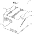
- Fig. 1 illustrates an exemplary device 10 as presented herein.
- the device 10 can include a carton or container 12, a rotatable member or elongated rotatable member 14 such as a reel or spool, and a support structure 16 featuring one or more slots 24 for rotatably supporting at least a portion of the reel 14 within the carton 12.
- the carton 12 can be comprised of a plurality of panels 18a-d joined together at their respective end edges and corners.
- the panels 18a-d can form an interior chamber, cavity or compartment 20 for storing the elongated flexible payout material 22, at least a portion of which can be wound around the exterior surface of the rotatable member 14.
- At least one of the panels 18a-18d can additionally include an opening 30 providing an egress for the material 22 to exit the container 12.
- the carton 12 can be made from any type of lightweight, durable and/or recyclable material, such as for example, cardboard, reinforced corrugated fiberboard, plastic, wood, fiberglass or plastic.
- the embodiment illustrated in Fig. 1 shows the device 10 as having a rectangular/cubical-shaped carton 12 formed by six flat panels 18a-18d having the same size/shape
- the carton 12 can feature more or less panels 18a-d as need be, can have curved panels, such as for example, where the carton 12 is cylindrical in shape, or can have panels 18a-d of different sizes.
- the carton 12 can additionally be customized to accommodate various sizes of reels 14 or different amounts of payout material 22, or can be produced or made available in standard uniform sizes or shapes to assist in warehousing or transportation.
- the support structure 16 can include one or more slots 24 which can be sized and shaped for receiving a portion of the rotatable member 14.
- the support structure 18 can be incorporated into the panels 18a-d, or can be separate structure(s) located within the interior compartment 20 of the carton 12 or outside the panels 18a-d.
- Fig. 1 illustrates the support structure 16 as including slots 24 integrated into opposing panels 18b, 18d for receiving the ends of the rotatable member 14.
- the slots 16 are spaced apart from one another and rotatably support the rotatable reel or spool 14 at opposing ends, with the length of the rotatable member 14 spanning the interior compartment 20 of the carton 12.
- the slots 16 can extend completely through the panels 18b, 18d to allow the ends of the rotatable member 14 to extend outside the carton 12, or merely be channels or grooves formed on the interior sides of the panels 18b, 18d.
- the support structure 16 can include plates (not pictured) secured to the interior or exterior of panels 18a-18d or a u-shaped bracket (not pictured) having a transverse portion joining opposing arms that extend substantially parallel to opposing panels 18a-d of the carton 12.
- the plates or arms of the support structure 16 can include at least one slot 24 of the type illustrated in Fig. 1 which can receive a portion of the rotatable member 14 and for rotatably supporting the member 14 at some point along its length.
- Fig. 1 illustrates slots 24 supporting the rotatable member 14 at the opposing ends, it will be recognized that such slot 24 can support the member 14 at any point along its length.
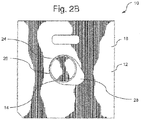
- Figs 1 and 2A-2B illustrate additional detail with regard to the slot(s) 24 according to embodiments presented herein.
- the slot 24 can have a tapered teardrop-shaped configuration having a wide larger diameter end 26 and a narrow smaller diameter end 28.
- the slot 24 can be sized and shaped to receive at least a portion of the rotatable member 14 so that it can slide between the larger diameter end 26 and the smaller diameter end 28.
- the larger diameter end 26 can be being sized to accommodate the full diameter of the rotatable member 14 such that the member 14 is able to rotate with minimal friction or resistance from the edge of the slot 24 when rotatable member 14 is in the larger diameter end 26.
- the smaller diameter end 28 of the slot 24 can be sized to have a diameter equal to or less than the diameter of the rotatable member 14, such that the small diameter end 28 either cannot receive the full diameter of the rotatable member 14 or provides a snug fit around the outer circumference of the member 14.
- the slot(s) 24 (and/or the support structure 16 for the slots 24) can be positioned on or in the carton 12 in an upright and forwardly angled position relative a vertical axis, whereby the larger diameter end 26 is elevated from the smaller diameter end 28 and is further positioned slightly closer to the opening 30.
- Fig. 1 illustrates an exemplary position of the slot 24 relative the opening 30.
- the rotatable member 14 extends substantially parallel to the horizontal surface such that the device can rely on gravity to provide a breaking mechanism.
- tension on the material 22 is absent or withdrawn, the rotatable member 14 will slide back towards the smaller diameter end 28 of the slot 24.
- Figs. 2A and 2B further illustrate the rotatable member 14 in varying positions within the slot 24.
- the rotatable member 14 is shown in a position representative of a "breaking" or “idle” position which is typical when no tension is being applied to the payout material 22 wound around the rotatable member 14.
- the member 14 can rest in a position towards the smaller diameter end 28 such that the outer circumference of the rotatable member 14 is in contact with portions of the edge of the slot 24.
- the edge of the slot 24 can provide resistance, friction or otherwise "pinch” the outer surface of the rotatable member 14 which can produce a breaking function preventing the rotatable member 14 from rotating.
- Such braking function can prevent unintended payout of the material 22 and can additionally cause the material 22 to slightly retract into the carton 12 to minimize the amount of extraneous material withdrawn from the carton 12.
- Fig. 2B illustrates the rotatable member 14 in a position representative of a "payout" position which can be typical when tension is being applied to the payout material 22 wound around the rotatable member 14.
- the rotatable member 14 can slide into a position towards the larger diameter end 26 of the slot 24 such that the edge of the slot 24 provides minimal contact or resistance to the outer circumference of the rotatable member 14.
- the member 14 can be allowed to rotate freely or with minimal resistance so that a user is able to easily withdraw as much material 22 as may be needed.
- embodiments of the subject invention can provide an automatic braking function which does not require a user to manually engage any braking device to stop the rotatable member 14 from further rotating.
- the subject device 12 can allow for little reactive tension on the payout material 22 while it is being pulled and additionally engage a braking function when no tension is applied to the material 22. It will be further recognized that additional benefits of the subject device are that it can be customer/user friendly in that it is relatively easy to use and requires little labor to operate or to load a new rotatable member 14 or payout material 22. In addition, the automated braking function can prevent excessive discharge of the payout material 22 which can typically result in wasted material and/or tangles or kinking of the material 22 which can require additional user attention and/or delay. Further benefits of the device disclosed herein are that it can be economical, easy to transport and be environmental-friendly.
- the device 10 can include a weighted or texturized base 32, including for example, a weighted plate or a tactile or texturized pad. Such features can provide the device 10 with greater grip strength and/or a lower center of gravity in order to keep the device from unintentionally sliding, tipping or being overturned during use.
- the exterior of the carton 12 can also include customized design elements 34, such as for example, bright colors or distinctive markings, lettering, graphics or logos to make it stand out, for commercial or advertising purposes or to conceal dirt or dust.
- the device can include a built-in cutting device 36 proximate the opening to enable a user to cut the desired amount of payout material once it has been withdrawn from the carton 12.
- the device 10 can additionally feature a handle 38 to assist with transporting the device.
- the handle 38 can extend away from a panel 18a of the carton, or be incorporated into a panel 18a-d as shown in Fig. 1 .
- the device 10 can additionally include an access door 40 on at least one panel 18a-d for accessing the interior compartment 20.
- the access door can be hinged, slidable or removable from the carton 12 as need be and can be an entire panel 18a-d or merely disposed on a portion of a panel.
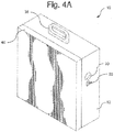
- Fig. 4A illustrates a device 10 with an access door 40 in a closed position enclosing the interior compartment 20.
- Fig. 4B illustrates a device 10 with a hinged access door 40 in an open position revealing the interior compartment 22.
- the door 40 can assist with changing or replacing the rotatable member 14 or the payout material 22. As shown in Fig.
- the interior compartment 20 of the device 10 can have a cylindrical or annular shape to conform with the shape of the rotatable member 14 and payout material 22 supported thereon.
- the cylindrically-shaped compartment 20 can facilitate smooth rotation of the payout material 22 around the interior compartment 20 when the member 14 is being rotated to prevent the material 22 from being snagged, caught or being accumulated in a corner of the compartment 22.
- the carton 12 can be reusable such that once a spool, reel or mandrel 14 of payout material 22 is exhausted, another can be easily loaded into the carton 12 or the material 22 can be reloaded on the existing member 14.
- the device 10 can be provided as a fully assembled unit or partially assembled as need be.
- the carton 12 can include slots, flaps or folds enabling the carton 12 to be easily collapsible for assembly and disassembly before or after use.
- one or more cartons 12 can be transported on a shipping pallet with the spool 14 and payout material 22 pre-loaded in place and ready for use, or such internal components can be provided within an assembled carton in an unassembled state.
- the carton 12 can be transported or provided in a collapsed unassembled state with the rotatable reel 14, support members 16 and payout material 22 accompanying the materials, or provided separately altogether.
Landscapes
- Details Of Rigid Or Semi-Rigid Containers (AREA)
- Cartons (AREA)
- Packaging Of Annular Or Rod-Shaped Articles, Wearing Apparel, Cassettes, Or The Like (AREA)
Applications Claiming Priority (2)
| Application Number | Priority Date | Filing Date | Title |
|---|---|---|---|
| US201461928545P | 2014-01-17 | 2014-01-17 | |
| US14/322,477 US9446928B2 (en) | 2014-01-17 | 2014-07-02 | Inertia braking payout device and package system |
Publications (2)
| Publication Number | Publication Date |
|---|---|
| EP2896586A1 EP2896586A1 (en) | 2015-07-22 |
| EP2896586B1 true EP2896586B1 (en) | 2017-04-19 |
Family
ID=52354779
Family Applications (1)
| Application Number | Title | Priority Date | Filing Date |
|---|---|---|---|
| EP15150979.1A Active EP2896586B1 (en) | 2014-01-17 | 2015-01-13 | Inertia braking payout device and package system |
Country Status (5)
| Country | Link |
|---|---|
| US (3) | US9446928B2 (enExample) |
| EP (1) | EP2896586B1 (enExample) |
| CN (1) | CN104787604B (enExample) |
| CA (1) | CA2877995C (enExample) |
| IN (1) | IN2015DE00119A (enExample) |
Families Citing this family (12)
| Publication number | Priority date | Publication date | Assignee | Title |
|---|---|---|---|---|
| US9446928B2 (en) * | 2014-01-17 | 2016-09-20 | Honeywell International Inc. | Inertia braking payout device and package system |
| DE102016224176B3 (de) * | 2016-12-06 | 2017-12-21 | Technisat Digital Gmbh | Vorrichtung und Verfahren zum Abwickeln eines Materials von einer Vorratstrommel |
| US10710835B2 (en) | 2016-12-28 | 2020-07-14 | Ademco Inc. | Collar retention system for packaging device for dispensing elongated flexible material |
| US11459205B2 (en) * | 2017-07-21 | 2022-10-04 | Belden, Inc | Corrugated cable dispenser |
| US20190225454A1 (en) * | 2018-01-24 | 2019-07-25 | Milliken & Company | Dispensing system for elongated elements |
| USD934061S1 (en) * | 2019-07-15 | 2021-10-26 | Cragg Technologies Llc | Cord pail |
| CN113353732B (zh) * | 2021-05-24 | 2022-09-02 | 绥化达昌亚麻纺织有限公司 | 一种纺织用丝线自动给进系统 |
| FR3123338B1 (fr) * | 2021-05-31 | 2025-09-26 | Nexans | Dispositif de stockage, transport et installation de fils et câbles électriques |
| US20250026607A1 (en) * | 2022-02-16 | 2025-01-23 | Fujikura Ltd. | Cable accommodating body |
| USD1073447S1 (en) * | 2023-10-16 | 2025-05-06 | Larry Ray Buck | Hose container |
| CN118495262B (zh) * | 2024-07-18 | 2024-09-13 | 山东合盛铜业有限公司 | 一种铜箔用收纳装置 |
| USD1072604S1 (en) * | 2025-01-15 | 2025-04-29 | Myeagle Pte. Ltd. | Garden hose reel |
Family Cites Families (9)
| Publication number | Priority date | Publication date | Assignee | Title |
|---|---|---|---|---|
| CA1010831A (en) * | 1974-06-17 | 1977-05-24 | Leon Kowalski | Azimuth seeking reeled primer cord dispenser |
| US4168778A (en) | 1978-04-24 | 1979-09-25 | Bemis Company, Inc. | Dispensing package |
| US4483491A (en) * | 1983-04-25 | 1984-11-20 | Rainey James R | Towel or tissue holder |
| US5967451A (en) | 1998-07-17 | 1999-10-19 | Radaios; Hristos | Cable wire spool |
| US6533077B1 (en) * | 2000-07-14 | 2003-03-18 | Otis Elevator Company | CSB (installation) dispensing tool and multi-belt hoisting clamp |
| US20100314483A1 (en) | 2009-06-15 | 2010-12-16 | Rain Bird Corporation | Method and Apparatus for Dispensing Tubing |
| US8662433B2 (en) * | 2009-12-18 | 2014-03-04 | Commscope, Inc. Of North Carolina | Reel-in-box cable package |
| FI125126B (fi) | 2011-09-23 | 2015-06-15 | Kone Corp | Menetelmä ja järjestely taipuisan elimen asentamiseksi hissiin ja taipuisan elimen asennuspakkaus |
| US9446928B2 (en) * | 2014-01-17 | 2016-09-20 | Honeywell International Inc. | Inertia braking payout device and package system |
-
2014
- 2014-07-02 US US14/322,477 patent/US9446928B2/en active Active
-
2015
- 2015-01-13 EP EP15150979.1A patent/EP2896586B1/en active Active
- 2015-01-14 IN IN119DE2015 patent/IN2015DE00119A/en unknown
- 2015-01-15 CA CA2877995A patent/CA2877995C/en active Active
- 2015-01-16 CN CN201510021816.7A patent/CN104787604B/zh active Active
-
2016
- 2016-09-19 US US15/269,683 patent/US10301142B2/en active Active
- 2016-09-19 US US15/269,750 patent/US10442655B2/en active Active
Non-Patent Citations (1)
| Title |
|---|
| None * |
Also Published As
| Publication number | Publication date |
|---|---|
| CN104787604B (zh) | 2018-09-18 |
| CA2877995C (en) | 2017-05-23 |
| CN104787604A (zh) | 2015-07-22 |
| US20170008726A1 (en) | 2017-01-12 |
| IN2015DE00119A (enExample) | 2015-07-24 |
| US20170008725A1 (en) | 2017-01-12 |
| US10301142B2 (en) | 2019-05-28 |
| CA2877995A1 (en) | 2015-07-17 |
| US20150203324A1 (en) | 2015-07-23 |
| US10442655B2 (en) | 2019-10-15 |
| EP2896586A1 (en) | 2015-07-22 |
| US9446928B2 (en) | 2016-09-20 |
Similar Documents
| Publication | Publication Date | Title |
|---|---|---|
| EP2896586B1 (en) | Inertia braking payout device and package system | |
| US5529186A (en) | Boxed pay-out reel for optic fiber cable or wire or the like, with smooth pay-out, high-impact and cable end holding features | |
| US8708144B2 (en) | Adapter for wire dispensing carton | |
| CN102459028A (zh) | 阀杆填密料分配器 | |
| US4168778A (en) | Dispensing package | |
| US7204367B2 (en) | Method and device for storing decorative light strings | |
| US7819354B2 (en) | Roll holder for tape dispenser and tape dispenser assembly therewith | |
| US9371171B1 (en) | Non-reel dispensing carton | |
| US11820622B1 (en) | Stackable wire-dispensing container | |
| US8360352B1 (en) | Reel for improved handling of lengthy flexible materials such as electrical cords, and the like | |
| US10710835B2 (en) | Collar retention system for packaging device for dispensing elongated flexible material | |
| WO2018026339A1 (ru) | Упаковка с нитевидным изделием | |
| KR200470261Y1 (ko) | 분리 장치 | |
| US20150028148A1 (en) | Product Containers with Rolled Goods | |
| US20050242225A1 (en) | Tape dispenser/package assembly | |
| KR20250000423U (ko) | 롤스티커 디스펜서 종이박스 | |
| KR20240025984A (ko) | 포장 및 개봉이 용이한 박스 | |
| JPH0232584Y2 (enExample) | ||
| US20050127234A1 (en) | Electrical wire dispensing device and package | |
| JP2012236668A (ja) | 線条体繰り出し装置 |
Legal Events
| Date | Code | Title | Description |
|---|---|---|---|
| PUAI | Public reference made under article 153(3) epc to a published international application that has entered the european phase |
Free format text: ORIGINAL CODE: 0009012 |
|
| 17P | Request for examination filed |
Effective date: 20150113 |
|
| AK | Designated contracting states |
Kind code of ref document: A1 Designated state(s): AL AT BE BG CH CY CZ DE DK EE ES FI FR GB GR HR HU IE IS IT LI LT LU LV MC MK MT NL NO PL PT RO RS SE SI SK SM TR |
|
| AX | Request for extension of the european patent |
Extension state: BA ME |
|
| RAP1 | Party data changed (applicant data changed or rights of an application transferred) |
Owner name: HONEYWELL INTERNATIONAL INC. |
|
| GRAP | Despatch of communication of intention to grant a patent |
Free format text: ORIGINAL CODE: EPIDOSNIGR1 |
|
| RIC1 | Information provided on ipc code assigned before grant |
Ipc: B65H 49/20 20060101ALI20161117BHEP Ipc: B65D 85/04 20060101ALI20161117BHEP Ipc: B65H 49/32 20060101AFI20161117BHEP |
|
| INTG | Intention to grant announced |
Effective date: 20161207 |
|
| GRAS | Grant fee paid |
Free format text: ORIGINAL CODE: EPIDOSNIGR3 |
|
| GRAA | (expected) grant |
Free format text: ORIGINAL CODE: 0009210 |
|
| AK | Designated contracting states |
Kind code of ref document: B1 Designated state(s): AL AT BE BG CH CY CZ DE DK EE ES FI FR GB GR HR HU IE IS IT LI LT LU LV MC MK MT NL NO PL PT RO RS SE SI SK SM TR |
|
| REG | Reference to a national code |
Ref country code: GB Ref legal event code: FG4D |
|
| REG | Reference to a national code |
Ref country code: CH Ref legal event code: EP |
|
| REG | Reference to a national code |
Ref country code: AT Ref legal event code: REF Ref document number: 885726 Country of ref document: AT Kind code of ref document: T Effective date: 20170515 |
|
| REG | Reference to a national code |
Ref country code: IE Ref legal event code: FG4D |
|
| REG | Reference to a national code |
Ref country code: DE Ref legal event code: R096 Ref document number: 602015002263 Country of ref document: DE |
|
| REG | Reference to a national code |
Ref country code: NL Ref legal event code: MP Effective date: 20170419 |
|
| REG | Reference to a national code |
Ref country code: LT Ref legal event code: MG4D |
|
| REG | Reference to a national code |
Ref country code: AT Ref legal event code: MK05 Ref document number: 885726 Country of ref document: AT Kind code of ref document: T Effective date: 20170419 |
|
| PG25 | Lapsed in a contracting state [announced via postgrant information from national office to epo] |
Ref country code: NL Free format text: LAPSE BECAUSE OF FAILURE TO SUBMIT A TRANSLATION OF THE DESCRIPTION OR TO PAY THE FEE WITHIN THE PRESCRIBED TIME-LIMIT Effective date: 20170419 |
|
| PG25 | Lapsed in a contracting state [announced via postgrant information from national office to epo] |
Ref country code: ES Free format text: LAPSE BECAUSE OF FAILURE TO SUBMIT A TRANSLATION OF THE DESCRIPTION OR TO PAY THE FEE WITHIN THE PRESCRIBED TIME-LIMIT Effective date: 20170419 Ref country code: HR Free format text: LAPSE BECAUSE OF FAILURE TO SUBMIT A TRANSLATION OF THE DESCRIPTION OR TO PAY THE FEE WITHIN THE PRESCRIBED TIME-LIMIT Effective date: 20170419 Ref country code: NO Free format text: LAPSE BECAUSE OF FAILURE TO SUBMIT A TRANSLATION OF THE DESCRIPTION OR TO PAY THE FEE WITHIN THE PRESCRIBED TIME-LIMIT Effective date: 20170719 Ref country code: LT Free format text: LAPSE BECAUSE OF FAILURE TO SUBMIT A TRANSLATION OF THE DESCRIPTION OR TO PAY THE FEE WITHIN THE PRESCRIBED TIME-LIMIT Effective date: 20170419 Ref country code: AT Free format text: LAPSE BECAUSE OF FAILURE TO SUBMIT A TRANSLATION OF THE DESCRIPTION OR TO PAY THE FEE WITHIN THE PRESCRIBED TIME-LIMIT Effective date: 20170419 Ref country code: GR Free format text: LAPSE BECAUSE OF FAILURE TO SUBMIT A TRANSLATION OF THE DESCRIPTION OR TO PAY THE FEE WITHIN THE PRESCRIBED TIME-LIMIT Effective date: 20170720 Ref country code: FI Free format text: LAPSE BECAUSE OF FAILURE TO SUBMIT A TRANSLATION OF THE DESCRIPTION OR TO PAY THE FEE WITHIN THE PRESCRIBED TIME-LIMIT Effective date: 20170419 |
|
| PG25 | Lapsed in a contracting state [announced via postgrant information from national office to epo] |
Ref country code: RS Free format text: LAPSE BECAUSE OF FAILURE TO SUBMIT A TRANSLATION OF THE DESCRIPTION OR TO PAY THE FEE WITHIN THE PRESCRIBED TIME-LIMIT Effective date: 20170419 Ref country code: IS Free format text: LAPSE BECAUSE OF FAILURE TO SUBMIT A TRANSLATION OF THE DESCRIPTION OR TO PAY THE FEE WITHIN THE PRESCRIBED TIME-LIMIT Effective date: 20170819 Ref country code: PL Free format text: LAPSE BECAUSE OF FAILURE TO SUBMIT A TRANSLATION OF THE DESCRIPTION OR TO PAY THE FEE WITHIN THE PRESCRIBED TIME-LIMIT Effective date: 20170419 Ref country code: BG Free format text: LAPSE BECAUSE OF FAILURE TO SUBMIT A TRANSLATION OF THE DESCRIPTION OR TO PAY THE FEE WITHIN THE PRESCRIBED TIME-LIMIT Effective date: 20170719 Ref country code: LV Free format text: LAPSE BECAUSE OF FAILURE TO SUBMIT A TRANSLATION OF THE DESCRIPTION OR TO PAY THE FEE WITHIN THE PRESCRIBED TIME-LIMIT Effective date: 20170419 Ref country code: SE Free format text: LAPSE BECAUSE OF FAILURE TO SUBMIT A TRANSLATION OF THE DESCRIPTION OR TO PAY THE FEE WITHIN THE PRESCRIBED TIME-LIMIT Effective date: 20170419 |
|
| REG | Reference to a national code |
Ref country code: DE Ref legal event code: R097 Ref document number: 602015002263 Country of ref document: DE |
|
| REG | Reference to a national code |
Ref country code: FR Ref legal event code: PLFP Year of fee payment: 4 |
|
| PG25 | Lapsed in a contracting state [announced via postgrant information from national office to epo] |
Ref country code: SK Free format text: LAPSE BECAUSE OF FAILURE TO SUBMIT A TRANSLATION OF THE DESCRIPTION OR TO PAY THE FEE WITHIN THE PRESCRIBED TIME-LIMIT Effective date: 20170419 Ref country code: EE Free format text: LAPSE BECAUSE OF FAILURE TO SUBMIT A TRANSLATION OF THE DESCRIPTION OR TO PAY THE FEE WITHIN THE PRESCRIBED TIME-LIMIT Effective date: 20170419 Ref country code: DK Free format text: LAPSE BECAUSE OF FAILURE TO SUBMIT A TRANSLATION OF THE DESCRIPTION OR TO PAY THE FEE WITHIN THE PRESCRIBED TIME-LIMIT Effective date: 20170419 Ref country code: RO Free format text: LAPSE BECAUSE OF FAILURE TO SUBMIT A TRANSLATION OF THE DESCRIPTION OR TO PAY THE FEE WITHIN THE PRESCRIBED TIME-LIMIT Effective date: 20170419 Ref country code: CZ Free format text: LAPSE BECAUSE OF FAILURE TO SUBMIT A TRANSLATION OF THE DESCRIPTION OR TO PAY THE FEE WITHIN THE PRESCRIBED TIME-LIMIT Effective date: 20170419 |
|
| PLBE | No opposition filed within time limit |
Free format text: ORIGINAL CODE: 0009261 |
|
| STAA | Information on the status of an ep patent application or granted ep patent |
Free format text: STATUS: NO OPPOSITION FILED WITHIN TIME LIMIT |
|
| PG25 | Lapsed in a contracting state [announced via postgrant information from national office to epo] |
Ref country code: SM Free format text: LAPSE BECAUSE OF FAILURE TO SUBMIT A TRANSLATION OF THE DESCRIPTION OR TO PAY THE FEE WITHIN THE PRESCRIBED TIME-LIMIT Effective date: 20170419 Ref country code: IT Free format text: LAPSE BECAUSE OF FAILURE TO SUBMIT A TRANSLATION OF THE DESCRIPTION OR TO PAY THE FEE WITHIN THE PRESCRIBED TIME-LIMIT Effective date: 20170419 |
|
| 26N | No opposition filed |
Effective date: 20180122 |
|
| PG25 | Lapsed in a contracting state [announced via postgrant information from national office to epo] |
Ref country code: SI Free format text: LAPSE BECAUSE OF FAILURE TO SUBMIT A TRANSLATION OF THE DESCRIPTION OR TO PAY THE FEE WITHIN THE PRESCRIBED TIME-LIMIT Effective date: 20170419 |
|
| REG | Reference to a national code |
Ref country code: CH Ref legal event code: PL |
|
| PG25 | Lapsed in a contracting state [announced via postgrant information from national office to epo] |
Ref country code: LU Free format text: LAPSE BECAUSE OF NON-PAYMENT OF DUE FEES Effective date: 20180113 |
|
| REG | Reference to a national code |
Ref country code: IE Ref legal event code: MM4A |
|
| REG | Reference to a national code |
Ref country code: BE Ref legal event code: MM Effective date: 20180131 |
|
| PG25 | Lapsed in a contracting state [announced via postgrant information from national office to epo] |
Ref country code: CH Free format text: LAPSE BECAUSE OF NON-PAYMENT OF DUE FEES Effective date: 20180131 Ref country code: LI Free format text: LAPSE BECAUSE OF NON-PAYMENT OF DUE FEES Effective date: 20180131 Ref country code: BE Free format text: LAPSE BECAUSE OF NON-PAYMENT OF DUE FEES Effective date: 20180131 |
|
| PG25 | Lapsed in a contracting state [announced via postgrant information from national office to epo] |
Ref country code: IE Free format text: LAPSE BECAUSE OF NON-PAYMENT OF DUE FEES Effective date: 20180113 |
|
| PG25 | Lapsed in a contracting state [announced via postgrant information from national office to epo] |
Ref country code: MC Free format text: LAPSE BECAUSE OF FAILURE TO SUBMIT A TRANSLATION OF THE DESCRIPTION OR TO PAY THE FEE WITHIN THE PRESCRIBED TIME-LIMIT Effective date: 20170419 |
|
| PG25 | Lapsed in a contracting state [announced via postgrant information from national office to epo] |
Ref country code: MT Free format text: LAPSE BECAUSE OF NON-PAYMENT OF DUE FEES Effective date: 20180113 |
|
| PG25 | Lapsed in a contracting state [announced via postgrant information from national office to epo] |
Ref country code: TR Free format text: LAPSE BECAUSE OF FAILURE TO SUBMIT A TRANSLATION OF THE DESCRIPTION OR TO PAY THE FEE WITHIN THE PRESCRIBED TIME-LIMIT Effective date: 20170419 |
|
| PG25 | Lapsed in a contracting state [announced via postgrant information from national office to epo] |
Ref country code: PT Free format text: LAPSE BECAUSE OF FAILURE TO SUBMIT A TRANSLATION OF THE DESCRIPTION OR TO PAY THE FEE WITHIN THE PRESCRIBED TIME-LIMIT Effective date: 20170419 |
|
| PG25 | Lapsed in a contracting state [announced via postgrant information from national office to epo] |
Ref country code: MK Free format text: LAPSE BECAUSE OF NON-PAYMENT OF DUE FEES Effective date: 20170419 Ref country code: HU Free format text: LAPSE BECAUSE OF FAILURE TO SUBMIT A TRANSLATION OF THE DESCRIPTION OR TO PAY THE FEE WITHIN THE PRESCRIBED TIME-LIMIT; INVALID AB INITIO Effective date: 20150113 Ref country code: CY Free format text: LAPSE BECAUSE OF FAILURE TO SUBMIT A TRANSLATION OF THE DESCRIPTION OR TO PAY THE FEE WITHIN THE PRESCRIBED TIME-LIMIT Effective date: 20170419 |
|
| PG25 | Lapsed in a contracting state [announced via postgrant information from national office to epo] |
Ref country code: AL Free format text: LAPSE BECAUSE OF FAILURE TO SUBMIT A TRANSLATION OF THE DESCRIPTION OR TO PAY THE FEE WITHIN THE PRESCRIBED TIME-LIMIT Effective date: 20170419 |
|
| REG | Reference to a national code |
Ref country code: GB Ref legal event code: 732E Free format text: REGISTERED BETWEEN 20201126 AND 20201202 |
|
| REG | Reference to a national code |
Ref country code: DE Ref legal event code: R081 Ref document number: 602015002263 Country of ref document: DE Owner name: ADEMCO INC., GOLDEN VALLEY, US Free format text: FORMER OWNER: HONEYWELL INTERNATIONAL INC., MORRIS PLAINS, N.J., US |
|
| P01 | Opt-out of the competence of the unified patent court (upc) registered |
Effective date: 20230601 |
|
| PGFP | Annual fee paid to national office [announced via postgrant information from national office to epo] |
Ref country code: DE Payment date: 20250129 Year of fee payment: 11 |
|
| PGFP | Annual fee paid to national office [announced via postgrant information from national office to epo] |
Ref country code: FR Payment date: 20250127 Year of fee payment: 11 |
|
| PGFP | Annual fee paid to national office [announced via postgrant information from national office to epo] |
Ref country code: GB Payment date: 20250127 Year of fee payment: 11 |