EP2896575A1 - Combination barrel made of two plastic barrels - Google Patents
Combination barrel made of two plastic barrels Download PDFInfo
- Publication number
- EP2896575A1 EP2896575A1 EP14194039.5A EP14194039A EP2896575A1 EP 2896575 A1 EP2896575 A1 EP 2896575A1 EP 14194039 A EP14194039 A EP 14194039A EP 2896575 A1 EP2896575 A1 EP 2896575A1
- Authority
- EP
- European Patent Office
- Prior art keywords
- barrel
- fassteil
- drum
- outer barrel
- combination
- Prior art date
- Legal status (The legal status is an assumption and is not a legal conclusion. Google has not performed a legal analysis and makes no representation as to the accuracy of the status listed.)
- Granted
Links
- 239000004033 plastic Substances 0.000 title claims abstract description 25
- 229920003023 plastic Polymers 0.000 title claims abstract description 25
- 238000004519 manufacturing process Methods 0.000 claims abstract description 11
- 238000000034 method Methods 0.000 claims description 26
- 238000003466 welding Methods 0.000 claims description 26
- 238000002844 melting Methods 0.000 claims description 16
- 230000008018 melting Effects 0.000 claims description 16
- 238000000071 blow moulding Methods 0.000 claims description 11
- 230000000295 complement effect Effects 0.000 claims description 5
- 230000004927 fusion Effects 0.000 claims description 5
- 210000003195 fascia Anatomy 0.000 claims description 4
- 238000003780 insertion Methods 0.000 claims description 2
- 230000037431 insertion Effects 0.000 claims description 2
- 238000000926 separation method Methods 0.000 claims 1
- 239000000126 substance Substances 0.000 description 5
- 229910000831 Steel Inorganic materials 0.000 description 4
- 239000010959 steel Substances 0.000 description 4
- 238000005304 joining Methods 0.000 description 3
- 239000000463 material Substances 0.000 description 3
- 230000001419 dependent effect Effects 0.000 description 2
- 239000007788 liquid Substances 0.000 description 2
- 239000002184 metal Substances 0.000 description 2
- 238000009423 ventilation Methods 0.000 description 2
- 230000015572 biosynthetic process Effects 0.000 description 1
- 238000001816 cooling Methods 0.000 description 1
- 230000003247 decreasing effect Effects 0.000 description 1
- 238000011161 development Methods 0.000 description 1
- 230000018109 developmental process Effects 0.000 description 1
- 239000012799 electrically-conductive coating Substances 0.000 description 1
- 238000007689 inspection Methods 0.000 description 1
- 239000000155 melt Substances 0.000 description 1
- 239000007769 metal material Substances 0.000 description 1
- 238000003860 storage Methods 0.000 description 1
Images


Classifications
-
- B—PERFORMING OPERATIONS; TRANSPORTING
- B65—CONVEYING; PACKING; STORING; HANDLING THIN OR FILAMENTARY MATERIAL
- B65D—CONTAINERS FOR STORAGE OR TRANSPORT OF ARTICLES OR MATERIALS, e.g. BAGS, BARRELS, BOTTLES, BOXES, CANS, CARTONS, CRATES, DRUMS, JARS, TANKS, HOPPERS, FORWARDING CONTAINERS; ACCESSORIES, CLOSURES, OR FITTINGS THEREFOR; PACKAGING ELEMENTS; PACKAGES
- B65D25/00—Details of other kinds or types of rigid or semi-rigid containers
- B65D25/20—External fittings
- B65D25/24—External fittings for spacing bases of containers from supporting surfaces, e.g. legs
-
- B—PERFORMING OPERATIONS; TRANSPORTING
- B65—CONVEYING; PACKING; STORING; HANDLING THIN OR FILAMENTARY MATERIAL
- B65D—CONTAINERS FOR STORAGE OR TRANSPORT OF ARTICLES OR MATERIALS, e.g. BAGS, BARRELS, BOTTLES, BOXES, CANS, CARTONS, CRATES, DRUMS, JARS, TANKS, HOPPERS, FORWARDING CONTAINERS; ACCESSORIES, CLOSURES, OR FITTINGS THEREFOR; PACKAGING ELEMENTS; PACKAGES
- B65D11/00—Containers having bodies formed by interconnecting or uniting two or more rigid, or substantially rigid, components made wholly or mainly of plastics material
- B65D11/02—Containers having bodies formed by interconnecting or uniting two or more rigid, or substantially rigid, components made wholly or mainly of plastics material of curved cross-section
- B65D11/06—Drums or barrels
- B65D11/08—Arrangements of filling or discharging apertures
-
- B—PERFORMING OPERATIONS; TRANSPORTING
- B65—CONVEYING; PACKING; STORING; HANDLING THIN OR FILAMENTARY MATERIAL
- B65D—CONTAINERS FOR STORAGE OR TRANSPORT OF ARTICLES OR MATERIALS, e.g. BAGS, BARRELS, BOTTLES, BOXES, CANS, CARTONS, CRATES, DRUMS, JARS, TANKS, HOPPERS, FORWARDING CONTAINERS; ACCESSORIES, CLOSURES, OR FITTINGS THEREFOR; PACKAGING ELEMENTS; PACKAGES
- B65D11/00—Containers having bodies formed by interconnecting or uniting two or more rigid, or substantially rigid, components made wholly or mainly of plastics material
- B65D11/16—Containers having bodies formed by interconnecting or uniting two or more rigid, or substantially rigid, components made wholly or mainly of plastics material with double walls
Definitions
- the invention relates to a combination drum comprising an outer drum and an inner drum accommodated in the outer drum.
- the body of the outer barrel is formed from a first and a second Fassteil, wherein the first Fassteil has a first connection portion and the second Fassteil a complementary to the first connection region formed second connection region. Furthermore, the invention relates to a method for producing such combination kegs.
- combination kegs consist of an outer drum made of sheet steel and an inner drum made of plastic.
- the inner drums can not be made of steel, as combination drums are often used to transport and store aggressive chemicals and steel is not resistant enough to such aggressive chemicals.
- combination drums are also used for chemicals with a low vapor pressure. If barrels were used for this purpose from only one container, they would be deformed on cooling of the chemicals due to the decreasing vapor pressure and thus resulting negative pressure. This has the consequence that the barrels, if they are stacked, for example, can fall down or can not be handled. Furthermore, such simple barrels can implode in this case in the empty state.
- the use of combination drums has the advantage that at least the outer container, ie the outer drum, does not deform and thus the shape remains stable.
- combination kegs can be made from a metal outer keg and a plastic barrel are not used or only at the cost of certain disadvantages.
- Combination kegs in order to be approved for the transport and storage of dangerous goods, must comply with UN directives, i. There are numerous extensive approval tests must be passed.
- the combination drum consists of an outer drum and an inner drum accommodated in the outer drum, wherein the body of the outer drum is formed by a first and a second drum part, which are connected to one another by way of two complementary connection areas.
- first and the second Fassteil are firmly connected.
- Both the inner and the outer barrel are made of a plastic.
- the combination drum is constructed entirely of plastic.
- the combination drum can also be used in areas where Metallic materials are undesirable. Nevertheless, the desired security is achieved and the UN guidelines can be met.
- the use of plastic has the advantage that the barrel is much lighter and thus easier to handle.
- first and the second Fasteils are welded together at the connection area. This ensures that a secure attachment of the two parts of the outer barrel is achieved after the introduction of the inner barrel and yet an economical production is possible.
- a welding method for joining the two parts it is possible to achieve that the geometry of the outer barrel, in particular the outer geometry, is not influenced and thus that for the fulfillment of security inspection requirements, e.g. Internal pressure test, cold drop test, established requirements are met.
- security inspection requirements e.g. Internal pressure test, cold drop test, established requirements are met.
- the combination drum in its outer shape compared to standard plastic drums does not have to be changed and thus its behavior is not affected in the individual test steps.
- the weld is in particular designed such that it does not change the outer contour of the outer barrel, so that always the same barrel shape can be guaranteed.
- the use of welding methods makes it possible for the attachment of the two barrel parts of the outer barrel to be reproducible and thus to ensure that the desired properties are achieved.
- the welding is carried out in particular via a fusion welding process, in which preferably a melting mirror is used for connecting the barrel parts.
- first and the second connection region are conical, so that their connection takes place via an inner surface which does not influence the geometry of the drum.
- the largest possible and thus safer connection area can be achieved via the conical forming.
- the inner barrel and the outer barrel are preferably each made in a blow molding process, so that a simple, safe and yet accurate production is possible.
- the first and second Fas part of the outer barrel are made of the same plastic, so that it is ensured during welding that these plastics optimally connect with each other.
- the inner drum can be made of the same plastic.
- the inner and outer drum can be made of different plastics, in particular, the inner drum can be adapted to the male chemicals.
- the first Fassteil forms the bottom and the side wall of the outer barrel
- the second Fassteil the outer barrel forms the lid of the outer barrel.
- the first Fas part also form the lid and the side wall and the second Fassteil exclusively the ground. This ensures that the connection point is automatically arranged in the already provided conical areas at the ends of the barrel.
- the inner contour of the outer barrel and the outer contour of the inner barrel are in particular matched to one another and formed substantially the same, so that the inner barrel fits optimally on the outer barrel and, if possible, can not slip. Furthermore, this makes optimum use of the available volume.
- the drum lid of the outer drum is designed in such a way that it has a channel and if a drain opening is provided from which liquid collecting in the drain can drain.
- This drain opening is designed such that it passes through the welded area, that is to say through the two connection areas.
- the combination drum has at least one ventilation valve, which is preferably arranged in the region of the lid and extends through the outer drum.
- Another aspect of the invention relates to a method for producing a combination keg, in which an inner drum is made of plastic. Further, a first Fas portion of an outer barrel and a second Fassteil the outer barrel is made of a plastic, wherein the first Fas part is made such that it is made a first connection portion and the second Fassteil such that it has a second connection region to the first connection region complementary.
- the inner drum is inserted through an opening of the first barrel part in this. Subsequently, the first opening of the first barrel portion is closed with the second Fassteil, wherein the second Fassteil this is placed accordingly and the two Faded are firmly connected to each other in the connecting areas.
- the two barrel parts of the outer barrel are in particular welded together, which has the advantage that a simple economic method for connecting the two barrel parts is achieved, but still a reproducible secure connection between the two barrel parts takes place.
- a fusion welding process is used to weld the two structural parts, which can be carried out in particular with the aid of a welding mirror.
- This has the advantage that the welding process can be carried out very accurately and reproducibly and in particular is not influenced by the connection of the two parts, not the outer shape of the outer barrel. This ensures that the form required for handling and compliance with security policies is maintained.
- the welding mirror is first arranged at the connecting region of the first barrel part.
- the inner drum is introduced into the first barrel portion of the outer barrel only when the melting time of the melting mirror has passed, that is, when the melting point of the melting pot has passed. when the melting mirror has already melted in the connecting region, the material of the first barrel portion. Subsequently, the second Fassteil is placed.
- the inner barrel may first be inserted into the first barrel portion and then commenced the welding process, i. that only then the melting mirror is placed on the first connection area and is started with the melting of the material.
- the melting takes place simultaneously with the aid of the melting mirror and the insertion of the inner barrel into the first Fas portion of the outer barrel. As a result, a particularly fast manufacturing process is achieved.
- the inner barrel and the outer barrel are each produced by the blow molding process.
- the first and second barrel portions of the outer barrel are combined in a single operation of a blow molding process from a melt tube as a workpiece made, which is then separated into the two parts.
- the workpiece is first formed such that the second fitting part is disposed "upside down", ie, rotated by 180 °, as compared with the position where it is finally welded to the first fitting part.
- the second Fassteil is rotated by 180 ° and welded in its intended orientation to the first Fassteil.
- first and / or second gripping part are made of an electrically conductive plastic.
- the entire first and / or second Fassteil can be made of an electrically conductive plastic.
- only an electrically conductive coating can also be provided here.
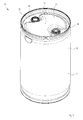
- FIG. 1 is a schematic perspective view of a combination drum 10 is shown.
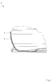
- FIG. 2 shows a sectional view of the combination keg after FIG. 1 .
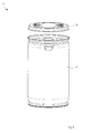
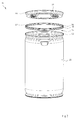
- FIG. 3 and 4 in each case a section of this sectional view FIG. 2 ,
- the combination drum 10 which is often also referred to as a combined drum, comprises an inner drum 12, which is also referred to as an inliner, and an outer drum 14.
- the inner drum 12 is in this case received in the outer drum 14, wherein the shapes of the inner drum 12 and the outer drum 14 are coordinated.
- the outer contour of the inner barrel 12 is substantially identical to the inner contour of the outer barrel 14, so that they fit optimally into one another and no space is given away.
- the outer surface 16 of the outer barrel and / or the inner surface 18 of the inner barrel can in particular be made of an electrically conductive plastic.
- the entire outer barrel 14 can be made of an electrically conductive plastic.
- Both the inner barrel 12 and the outer barrel 14 are in particular made of plastic in a blow molding process, so that a simple inexpensive and yet precise production is possible.
- the outer barrel 14 consists of a first Fassteil 20, in which in the FIGS. 1 to 7 illustrated first embodiment forms the bottom or the side wall of the barrel, and a second Fassteil 22, which forms the lid of the outer barrel 14 in the first embodiment.
- a ventilation valve 24 and filling openings 26, 28 are provided, which pass through the outer drum 14 therethrough.
- the lid 22 is preferably formed such that a groove 30 is formed in it.
- a drain opening 32 is provided, which passes through both the first Fassteil 20 and the second Fassteil 22, so the lid. About this drain opening 32 can drain liquid collected in the channel 30.
- Both the inner barrel 12 and the outer barrel 14 are made of a plastic by means of blow molding.
- the outer barrel 14 wherein the first Fassteil 20 and the second Fassteil 22 are formed contiguous.
- the second Fassteil 22 so the lid, separated from the first Fassteil 20.
- the second Fassteil 22 is compared with the state where it is attached to the blow molding on the first Fassteil 20, rotated by 180 ° and, after the inner barrel 12 through the opening 34 of the first barrel portion 20 in the first Fassteil 20 of the outer barrel 14 has been used, permanently and firmly welded to the first Fassteil 20.
- the welding of the two parts of the outer barrel 14 takes place by means of a fusion welding process carried out via a welding mirror 36.
- a welding mirror 36 For this purpose, outer surface 38 of the welding mirror 36 corresponding to the connecting region 40 of the first barrel part 20 and the inner side 42 corresponding to the connecting region 44 of the second barrel part 22 are formed. The material is melted in the area of the connecting regions 40, 44 via the melting mirror 36, so that the two clamping parts 20, 22 can be connected to one another permanently, safely and without the formation of an outwardly directed weld seam.
- a combination drum 10 can be produced in a simple and efficient manner, which consists exclusively of plastic and yet meets the high safety requirements for the transport of dangerous goods.
- connection of the two barrel parts 20, 22 of the outer barrel 14 takes place only after the inner barrel 12 has been introduced.
- the inner barrel 12 can be inserted into the first Fassteil 20 before the welding process is started.
- the welding mirror 36 can be placed on the connecting region 40 and the inner barrel 12 can be inserted only after completion of the melting, but of course before joining the two barrel parts 20, 22.
- both components 20, 22 By manufacturing both components 20, 22 in a single blow molding process on the one hand, a fast, inexpensive and effective production is achieved. Furthermore, this ensures that the two parts are formed from the same plastic and thus can be optimally welded together, which further increases safety.
- the first fascia 102 includes the lid and side wall of the outer barrel 14 and the second fascia 104 only the bottom. Accordingly, the welded connection is arranged at the lower end of the drum 10.
- FIG. 9 it is shown how, in this embodiment, the welding mirror 106 is arranged between the two fitting parts 102, 104 in order to melt the connecting regions 40, 44.
- FIG. 10 the state is shown after the melting mirror 106 has been removed, so that the two parts 102, 104 can be connected to each other according to the arrow P1.
- FIG. 11 shows a partially sectioned view of a combination keg 200 according to a third embodiment of the invention.
- the first chamfer 202 includes the bottom and the side wall of the outer barrel 14.
- the second chamfer 204 is again formed in the shape of the lid, however, the lid 204 in this embodiment becomes different from the first embodiment , put on the first Fasteil 202 from the outside.
- the welding takes place in each case in a conical region of the outer barrel 14.
- the connecting regions 40, 44 via which the two fitting parts 20, 22, 102, 104, 202, 204 are connected to one another, are likewise conical. This has the advantage that the largest possible welding surface is formed and, in particular, no weld seam which influences the outer contour is produced.
- the connecting portions 40, 44 may also have a shape deviating from the conical shape.
Landscapes
- Engineering & Computer Science (AREA)
- Mechanical Engineering (AREA)
- Lining Or Joining Of Plastics Or The Like (AREA)
Abstract
Die Erfindung betrifft ein Kombinationsfass (10, 100, 200), das ein Außenfass (14) sowie ein Innenfass (12) umfasst, wobei das Außenfass (14) einen ersten Fassteil (20, 102, 202) und einen zweiten Fassteil (22, 104, 204) aufweist. Die beiden Fassteile (20, 22, 102, 202, 104, 202, 204) sind in einem Verbindungsbereich fest miteinander verbunden. Das Innenfass (12) als auch das Außenfass (14) sind aus einem Kunststoff gefertigt. Ferner betrifft die Erfindung ein Verfahren zum Herstellen eines solchen Kombinationsfasses (10, 100, 200).The invention relates to a combination drum (10, 100, 200) comprising an outer drum (14) and an inner drum (12), wherein the outer drum (14) has a first drum part (20, 102, 202) and a second drum part (22, 104, 204). The two grip parts (20, 22, 102, 202, 104, 202, 204) are firmly connected to one another in a connection region. The inner barrel (12) and the outer barrel (14) are made of a plastic. Furthermore, the invention relates to a method for producing such a combination keg (10, 100, 200).
Description
Die Erfindung betrifft ein Kombinationsfass, das ein Außenfass sowie ein in dem Außenfass aufgenommenes Innenfass umfasst. Der Körper des Außenfasses ist aus einem ersten und einem zweiten Fassteil gebildet, wobei der erste Fassteil einen ersten Verbindungsbereich und der zweite Fassteil einen komplementär zum ersten Verbindungsbereich ausgebildeten zweiten Verbindungsbereich aufweist. Ferner betrifft die Erfindung ein Verfahren zum Herstellen solcher Kombinationsfässer.The invention relates to a combination drum comprising an outer drum and an inner drum accommodated in the outer drum. The body of the outer barrel is formed from a first and a second Fassteil, wherein the first Fassteil has a first connection portion and the second Fassteil a complementary to the first connection region formed second connection region. Furthermore, the invention relates to a method for producing such combination kegs.
Bekannte Kombinationsfässer bestehen aus einem Außenfass aus Stahlblech sowie einen Innenfass aus Kunststoff. Die Innenfässer können nicht aus Stahl aufgebaut sein, da Kombinationsfässer häufig zum Transport und zur Lagerung von aggressiven Chemikalien verwendet werden und Stahl nicht beständig genug gegen solche aggressiven Chemikalien ist.Known combination kegs consist of an outer drum made of sheet steel and an inner drum made of plastic. The inner drums can not be made of steel, as combination drums are often used to transport and store aggressive chemicals and steel is not resistant enough to such aggressive chemicals.
Ferner werden Kombinationsfässer auch für Chemikalien mit einem niedrigen Dampfdruck eingesetzt. Würde man hierfür Fässer aus nur einem Behälter verwenden, würden sich diese bei Abkühlung der Chemikalien durch den sinkenden Dampfdruck und somit entstehenden Unterdruck verformen. Dies hat zur Folge, dass die Fässer, sofern sie übereinander gestapelt sind, beispielsweise herunterfallen können oder nicht gehandhabt werden können. Ferner können solche einfachen Fässer in diesem Fall im Leerzustand implodieren. Die Verwendung von Kombinationsfässern hat dagegen den Vorteil, dass zumindest der äußere Behälter, also das Außenfass, sich nicht verformt und somit die Form stabil bleibt.Furthermore, combination drums are also used for chemicals with a low vapor pressure. If barrels were used for this purpose from only one container, they would be deformed on cooling of the chemicals due to the decreasing vapor pressure and thus resulting negative pressure. This has the consequence that the barrels, if they are stacked, for example, can fall down or can not be handled. Furthermore, such simple barrels can implode in this case in the empty state. On the other hand, the use of combination drums has the advantage that at least the outer container, ie the outer drum, does not deform and thus the shape remains stable.
Es gibt jedoch Einsatzbereiche, in denen die Verwendung von metallischen Fässern Nachteile mit sich bringt. Deshalb können Kombinationsfässer aus einem Metallaußenfass und einem Kunststoffinnenfass nicht oder nur unter Inkaufnahme gewisser Nachteile eingesetzt werden.However, there are applications in which the use of metallic drums has disadvantages. Therefore, combination kegs can be made from a metal outer keg and a plastic barrel are not used or only at the cost of certain disadvantages.
Kombinationsfässer müssen, um für den Transport und die Lagerung von Gefahrengütern zugelassen zu werden, den UN-Richtlinien entsprechen, d.h. es müssen zahlreiche umfangreiche Zulassungsprüfungen bestanden werden.Combination kegs, in order to be approved for the transport and storage of dangerous goods, must comply with UN directives, i. There are numerous extensive approval tests must be passed.
Es ist Aufgabe der Erfindung, ein besonders einfach und leicht aufgebautes Kombinationsfass anzugeben. Ferner ist es Aufgabe der Erfindung, ein Verfahren zur Herstellung eines solchen Kombinationsfasses anzugeben.It is an object of the invention to provide a particularly simple and easy constructed combination drum. It is another object of the invention to provide a method for producing such a combination drum.
Die Aufgabe wird durch ein Kombinationsfass mit den Merkmalen des Anspruchs 1 sowie durch ein Verfahren mit den Merkmalen des unabhängigen Verfahrensanspruchs gelöst. Vorteilhafte Weiterbildungen der Erfindung sind in den abhängigen Ansprüchen angegeben.The object is achieved by a combination drum with the features of claim 1 and by a method having the features of the independent method claim. Advantageous developments of the invention are specified in the dependent claims.
Erfindungsgemäß besteht das Kombinationsfass aus einem Außenfass und einem in dem Außenfass aufgenommenen Innenfass, wobei der Körper des Außenfasses aus einem ersten und einem zweiten Fassteil gebildet ist, die über zwei komplementär zueinander ausgebildete Verbindungsbereiche miteinander verbunden sind. In einem zusammengebauten Zustand, d.h. in demjenigen Zustand, in dem das Kombinationsfass fertig zusammengebaut ist, sind das erste und das zweite Fassteil fest miteinander verbunden. Sowohl das Innen- als auch das Außenfass sind aus einem Kunststoff gefertigt.According to the invention, the combination drum consists of an outer drum and an inner drum accommodated in the outer drum, wherein the body of the outer drum is formed by a first and a second drum part, which are connected to one another by way of two complementary connection areas. In an assembled condition, i. in the state in which the combination keg is finished assembled, the first and the second Fassteil are firmly connected. Both the inner and the outer barrel are made of a plastic.
Hierdurch wird erreicht, dass auf Metall, insbesondere Stahlbleche, verzichtet werden kann und das Kombinationsfass ausschließlich aus Kunststoff aufgebaut ist. Hierdurch kann das Kombinationsfass auch in Bereichen verwendet werden, in denen metallische Werkstoffe unerwünscht sind. Dennoch wird die gewünschte Sicherheit erreicht und die UN-Richtlinien können erfüllt werden. Darüber hinaus hat die Verwendung von Kunststoff den Vorteil, dass das Fass wesentlich leichter aufgebaut ist und somit auch einfacher gehandhabt werden kann.This ensures that can be dispensed with metal, especially steel sheets, and the combination drum is constructed entirely of plastic. As a result, the combination drum can also be used in areas where Metallic materials are undesirable. Nevertheless, the desired security is achieved and the UN guidelines can be met. In addition, the use of plastic has the advantage that the barrel is much lighter and thus easier to handle.
Es ist vorteilhaft, wenn das erste und das zweite Fassteil am Verbindungsbereich miteinander verschweißt werden. Hierdurch wird erreicht, dass eine sichere Befestigung der beiden Teile des Außenfasses nach dem Einbringen des Innenfasses erreicht wird und dennoch eine wirtschaftliche Fertigung möglich ist. Darüber hinaus kann durch das Verwenden eines Schweißverfahrens zum Verbinden der beiden Teile erreicht werden, dass die Geometrie des Außenfasses, insbesondere die Außengeometrie nicht beeinflusst wird und somit die für das Erfüllen von Prüfanforderungen für die Sicherheit, z.B. Innendruck-Prüfung, Kältefalltest, aufgestellten Forderungen erfüllt werden. Insbesondere ist es somit möglich, dass das Kombinationsfass in seiner äußeren Form verglichen mit Standardkunststofffässern nicht verändert werden muss und somit sein Verhalten bei den einzelnen Prüfschritten nicht beeinträchtigt wird.It is advantageous if the first and the second Fasteils are welded together at the connection area. This ensures that a secure attachment of the two parts of the outer barrel is achieved after the introduction of the inner barrel and yet an economical production is possible. In addition, by using a welding method for joining the two parts, it is possible to achieve that the geometry of the outer barrel, in particular the outer geometry, is not influenced and thus that for the fulfillment of security inspection requirements, e.g. Internal pressure test, cold drop test, established requirements are met. In particular, it is thus possible that the combination drum in its outer shape compared to standard plastic drums does not have to be changed and thus its behavior is not affected in the individual test steps.
Die Schweißnaht ist insbesondere derart ausgebildet, dass sie die Außenkontur des Außenfasses nicht verändert, so dass immer die gleiche Fassform gewährleistet werden kann.The weld is in particular designed such that it does not change the outer contour of the outer barrel, so that always the same barrel shape can be guaranteed.
Insbesondere ermöglicht die Verwendung von Schweißverfahren, dass die Befestigung der beiden Fassteile des Außenfasses reproduzierbar ist und somit sichergestellt werden kann, dass die gewünschten Eigenschaften erreicht werden. Hierzu erfolgt das Schweißen insbesondere über ein Schmelzschweißverfahren, bei dem vorzugsweise ein Schmelzspiegel zum Verbinden der Fassteile eingesetzt wird.In particular, the use of welding methods makes it possible for the attachment of the two barrel parts of the outer barrel to be reproducible and thus to ensure that the desired properties are achieved. For this purpose, the welding is carried out in particular via a fusion welding process, in which preferably a melting mirror is used for connecting the barrel parts.
Ferner ist es vorteilhaft, wenn der erste und der zweite Verbindungsbereich konisch ausgebildet sind, so dass deren Verbindung miteinander über eine innenliegenden Fläche erfolgt, die die Geometrie des Fasses nicht beeinflusst. Darüber hinaus kann über das konische Ausbilden ein möglichst großer und somit sicherer Verbindungsbereich erreicht werden.Furthermore, it is advantageous if the first and the second connection region are conical, so that their connection takes place via an inner surface which does not influence the geometry of the drum. In addition, the largest possible and thus safer connection area can be achieved via the conical forming.
Das Innenfass und das Außenfass werden vorzugsweise jeweils in einem Blasformverfahren hergestellt, so dass eine einfache, sichere und trotzdem genaue Fertigung möglich ist.The inner barrel and the outer barrel are preferably each made in a blow molding process, so that a simple, safe and yet accurate production is possible.
Ferner ist es vorteilhaft, wenn das erste und das zweite Fassteil des Außenfasses aus demselben Kunststoff gefertigt sind, so dass beim Schweißen sichergestellt ist, dass diese Kunststoffe sich optimal miteinander verbinden. Ferner kann auch das Innenfass aus dem gleichen Kunststoff gefertigt sein. Alternativ können auch das Innenund Außenfass aus unterschiedlichen Kunststoffen gefertigt sein, insbesondere kann das Innenfass an die aufzunehmenden Chemikalien angepasst sein.Further, it is advantageous if the first and second Fas part of the outer barrel are made of the same plastic, so that it is ensured during welding that these plastics optimally connect with each other. Furthermore, the inner drum can be made of the same plastic. Alternatively, the inner and outer drum can be made of different plastics, in particular, the inner drum can be adapted to the male chemicals.
Bei einer bevorzugten Ausführungsform der Erfindung bildet der erste Fassteil den Boden und die Seitenwand des Außenfasses, wohingegen der zweite Fassteil des Außenfasses den Deckel des Außenfasses bildet. Alternativ kann der erste Fassteil auch den Deckel und die Seitenwand bilden und der zweite Fassteil ausschließlich den Boden. Hierdurch wird erreicht, dass die Verbindungsstelle automatisch in den ohnehin vorgesehenen konischen Bereichen an den Enden des Fasses angeordnet ist.In a preferred embodiment of the invention, the first Fassteil forms the bottom and the side wall of the outer barrel, whereas the second Fassteil the outer barrel forms the lid of the outer barrel. Alternatively, the first Fas part also form the lid and the side wall and the second Fassteil exclusively the ground. This ensures that the connection point is automatically arranged in the already provided conical areas at the ends of the barrel.
Die Innenkontur des Außenfasses und die Außenkontur des Innenfasses sind insbesondere aufeinander abgestimmt und im Wesentlichen gleich ausgebildet, so dass das Innenfass optimal am Außenfass anliegt und möglichst nicht verrutschen kann. Ferner wird hierdurch das zur Verfügung stehende Volumen optimal ausgenutzt.The inner contour of the outer barrel and the outer contour of the inner barrel are in particular matched to one another and formed substantially the same, so that the inner barrel fits optimally on the outer barrel and, if possible, can not slip. Furthermore, this makes optimum use of the available volume.
Ferner ist es vorteilhaft, wenn der Fassdeckel des Außenfasses derart gestaltet ist, dass er eine Rinne aufweist und wenn eine Ablauföffnung vorgesehen ist, aus der sich in der Rinne sammelnde Flüssigkeit ablaufen kann. Diese Ablauföffnung ist derart ausgebildet, dass sie durch den verschweißten Bereich, also durch die beiden Verbindungsbereiche, hindurch verläuft.Furthermore, it is advantageous if the drum lid of the outer drum is designed in such a way that it has a channel and if a drain opening is provided from which liquid collecting in the drain can drain. This drain opening is designed such that it passes through the welded area, that is to say through the two connection areas.
Ferner ist es vorteilhaft, wenn das Kombinationsfass mindestens ein Belüftungsventil aufweist, welches vorzugsweise im Bereich des Deckels angeordnet ist und durch das Außenfass hindurch verläuft.Furthermore, it is advantageous if the combination drum has at least one ventilation valve, which is preferably arranged in the region of the lid and extends through the outer drum.
Ein weiterer Aspekt der Erfindung betrifft ein Verfahren zum Herstellen eines Kombinationsfasses, bei dem ein Innenfass aus Kunststoff gefertigt wird. Ferner wird ein erstes Fassteil eines Außenfasses und ein zweites Fassteil des Außenfasses aus einem Kunststoff gefertigt, wobei das erste Fassteil derart gefertigt wird, dass es einen ersten Verbindungsbereich und das zweite Fassteil derart gefertigt wird, dass es einen zum ersten Verbindungsbereich komplementären zweiten Verbindungsbereich aufweist. Das Innenfass wird über eine Öffnung des ersten Fassteils in diesen eingesetzt. Anschließend wird die erste Öffnung des ersten Fassteils mit dem zweiten Fassteil verschlossen, wobei das zweite Fassteil hierzu entsprechend aufgesetzt wird und die beiden Fassteile in den Verbindungsbereichen fest miteinander verbunden werden.Another aspect of the invention relates to a method for producing a combination keg, in which an inner drum is made of plastic. Further, a first Fas portion of an outer barrel and a second Fassteil the outer barrel is made of a plastic, wherein the first Fas part is made such that it is made a first connection portion and the second Fassteil such that it has a second connection region to the first connection region complementary. The inner drum is inserted through an opening of the first barrel part in this. Subsequently, the first opening of the first barrel portion is closed with the second Fassteil, wherein the second Fassteil this is placed accordingly and the two Faßtile are firmly connected to each other in the connecting areas.
Die beiden Fassteile des Außenfasses werden insbesondere miteinander verschweißt, was den Vorteil hat, dass ein einfaches wirtschaftliches Verfahren zum Verbinden der beiden Fassteile erreicht wird, aber dennoch eine reproduzierbare sichere Verbindung zwischen den beiden Fassteilen erfolgt.The two barrel parts of the outer barrel are in particular welded together, which has the advantage that a simple economic method for connecting the two barrel parts is achieved, but still a reproducible secure connection between the two barrel parts takes place.
Insbesondere wird zum Verschweißen der beiden Fassteile ein Schmelzschweißverfahren verwendet, was insbesondere mit Hilfe eines Schweißspiegels durchgeführt werden kann. Dies hat den Vorteil, dass der Schweißprozess sehr genau und reproduzierbar ausgeführt werden kann und insbesondere auch über die Verbindung der beiden Teile nicht die Außenform des Außenfasses beeinflusst wird. Somit wird sichergestellt, dass die für die Handhabung und für die Erfüllung von Sicherheitsrichtlinien wichtige Form erhalten bleibt.In particular, a fusion welding process is used to weld the two structural parts, which can be carried out in particular with the aid of a welding mirror. This has the advantage that the welding process can be carried out very accurately and reproducibly and in particular is not influenced by the connection of the two parts, not the outer shape of the outer barrel. This ensures that the form required for handling and compliance with security policies is maintained.
Bei einem möglichen Verfahren wird der Schweißspiegel zunächst an dem Verbindungsbereich des ersten Fassteils angeordnet. Das Innenfass wird erst in das erste Fassteil des Außenfasses eingeführt, wenn die Aufschmelzzeit des Schmelzspiegels vergangen ist, d.h. wenn der Schmelzspiegel bereits in dem Verbindungsbereich das Material des ersten Fassteils aufgeschmolzen hat. Anschließend wird das zweite Fassteil aufgesetzt.In one possible method, the welding mirror is first arranged at the connecting region of the first barrel part. The inner drum is introduced into the first barrel portion of the outer barrel only when the melting time of the melting mirror has passed, that is, when the melting point of the melting pot has passed. when the melting mirror has already melted in the connecting region, the material of the first barrel portion. Subsequently, the second Fassteil is placed.
Bei einem alternativen Verfahren kann auch zunächst das Innenfass in das erste Fassteil eingeführt werden und dann mit dem Schweißprozess begonnen werden, d.h. dass erst dann der Schmelzspiegel an den ersten Verbindungsbereich angeordnet wird und mit dem Aufschmelzen des Materials begonnen wird.In an alternative method, the inner barrel may first be inserted into the first barrel portion and then commenced the welding process, i. that only then the melting mirror is placed on the first connection area and is started with the melting of the material.
Ferner ist es alternativ auch möglich, dass das Schmelzen mit Hilfe des Schmelzspiegels und das Einführen des Innenfasses in den ersten Fassteil des Außenfasses zeitgleich erfolgt. Hierdurch wird ein besonders schnelles Fertigungsverfahren erreicht.Furthermore, it is alternatively also possible that the melting takes place simultaneously with the aid of the melting mirror and the insertion of the inner barrel into the first Fas portion of the outer barrel. As a result, a particularly fast manufacturing process is achieved.
Ferner ist vorteilhaft, wenn das Innenfass und das Außenfass jeweils im Blasformverfahren hergestellt werden. Bei einer besonders bevorzugten Ausführungsform werden der ersten und der zweite Fassteil des Außenfasses gemeinsam in einem einzigen Arbeitsgang eines Blasformverfahrens aus einem Schmelzschlauch als ein Werkstück hergestellt, das dann in die beiden Fassteile getrennt wird. Insbesondere wird bei diesem Blasformverfahren das Werkstück zunächst derart geformt, dass das zweite Fassteil verglichen mit der Position, in der es am Ende an dem ersten Fassteil angeschweißt wird, "falsch herum", d.h. um 180° verdreht, angeordnet ist. Nach dem Trennen der beiden Fassteile wird das zweite Fassteil um 180° gedreht und in seiner bestimmungsgemäßen Ausrichtung an das erste Fassteil angeschweißt.Furthermore, it is advantageous if the inner barrel and the outer barrel are each produced by the blow molding process. In a particularly preferred embodiment, the first and second barrel portions of the outer barrel are combined in a single operation of a blow molding process from a melt tube as a workpiece made, which is then separated into the two parts. Specifically, in this blow molding method, the workpiece is first formed such that the second fitting part is disposed "upside down", ie, rotated by 180 °, as compared with the position where it is finally welded to the first fitting part. After separating the two barrel parts, the second Fassteil is rotated by 180 ° and welded in its intended orientation to the first Fassteil.
Ferner ist es vorteilhaft, wenn zumindest die innere und/oder äußere Oberfläche des ersten und/oder zweiten Fassteiles aus einem elektrisch leitfähigen Kunststoff gefertigt sind. Insbesondere kann auch das gesamte erste und/oder zweite Fassteil aus einem elektrisch leitenden Kunststoff gefertigt werden. Alternativ kann auch hier lediglich eine elektrisch leitende Beschichtung vorgesehen sein.Furthermore, it is advantageous if at least the inner and / or outer surface of the first and / or second gripping part are made of an electrically conductive plastic. In particular, the entire first and / or second Fassteil can be made of an electrically conductive plastic. Alternatively, only an electrically conductive coating can also be provided here.
Das zuvor beschriebene Verfahren kann mit den in den auf den unabhängigen Vorrichtungsanspruch rückbezogenen Ansprüchen angegebenen Merkmalen bzw. entsprechenden Verfahrensmerkmalen weitergebildet werden. Umgekehrt kann die durch den unabhängigen Vorrichtungsanspruch angegebene Vorrichtung durch die in den Verfahrensansprüchen angegebenen Merkmalen bzw. entsprechenden Vorrichtungsmerkmalen weiter gebildet werden.The method described above can be further developed with the features or corresponding method features specified in the claims dependent on the independent device claim. Conversely, the device indicated by the independent apparatus claim may be further formed by the features set forth in the method claims and corresponding apparatus features, respectively.
Weitere Merkmale und Vorteile der Erfindung ergeben sich aus der folgenden Beschreibung. Die Erfindung wird anhand von Ausführungsbeispielen in Zusammenhang mit den beigefügten Figuren näher erläutert.Further features and advantages of the invention will become apparent from the following description. The invention will be explained in more detail by means of exemplary embodiments in conjunction with the attached figures.
Es zeigen:
- Figur 1
- Eine schematische, perspektivische Darstellung eines Kombinationsfasses gemäß einer ersten Ausführungsform;
- Figur 2
- eine Schnittdarstellung des Kombinationsfasses nach
Figur 1 ; - Figur 3
- einen vergrößerten Ausschnitt der Schnittdarstellung nach
Figur 2 ; - Figur 4
- einen weiteren vergrößerten Ausschnitt der Schnittdarstellung nach Figur 2;
- Figur 5
- eine Schnittdarstellung eines Außenfasses des Kombinationsfasses nach
Figur 1 nach der Beendigung eines Blasformverfahrens; - Figur 6
- eine schematische, perspektivische Darstellung des Außenfasses nach
Figur 5 mit abgetrenntem Deckel; - Figur 7
- eine Explosionsdarstellung des Außenfasses nach den
Figuren 5 und6 während eines Schmelzschweißvorgangs; - Figur 8
- eine teilgeschnittene Darstellung eines Kombinationsfasses gemäß einer zweiten Ausführungsform;
- Figur 9
- einen Ausschnitt einer Schnittdarstellung des Kombinationsfasses nach
Figur 8 während des Schweißvorgangs; Figur 10- eine weiteren Ausschnitt des Kombinationsfasses nach
Figur 8 vor dem Zusammenfügen der beiden Fassteile des Außenfasses; und - Figur 11
- eine teilgeschnittene Darstellung eines Kombinationsfasses gemäß einer dritten Ausführungsform.
- FIG. 1
- A schematic perspective view of a combination keg according to a first embodiment;
- FIG. 2
- a sectional view of the combination keg after
FIG. 1 ; - FIG. 3
- an enlarged section of the sectional view after
FIG. 2 ; - FIG. 4
- a further enlarged section of the sectional view of Figure 2;
- FIG. 5
- a sectional view of an outer barrel of the combination barrel after
FIG. 1 after the completion of a blow molding process; - FIG. 6
- a schematic perspective view of the outer barrel according to
FIG. 5 with separate lid; - FIG. 7
- an exploded view of the outer barrel after the
Figures 5 and6 during a fusion welding operation; - FIG. 8
- a partially sectioned view of a combination keg according to a second embodiment;
- FIG. 9
- a section of a sectional view of the combination keg after
FIG. 8 during the welding process; - FIG. 10
- another section of the combination keg after
FIG. 8 before joining the two parts of the outer barrel; and - FIG. 11
- a partially sectioned view of a combination keg according to a third embodiment.
In
Das Kombinationsfass 10, welches häufig kurz auch als Kombifass bezeichnet wird, umfasst ein Innenfass 12, welches auch als Inliner bezeichnet wird, sowie ein Außenfass 14. Das Innenfass 12 ist hierbei in dem Außenfass 14 aufgenommen, wobei die Formen des Innenfasses 12 und des Außenfasses 14 aufeinander abgestimmt sind. Insbesondere ist die Außenkontur des Innenfasses 12 im Wesentlichen identisch mit der Innenkontur des Außenfasses 14, so dass diese optimal ineinander passen und kein Platz verschenkt wird. Die äußere Oberfläche 16 des Außenfasses und/oder die innere Oberfläche 18 des Innenfasses können insbesondere aus einem elektrisch leitfähigen Kunststoff gefertigt sein. Alternativ kann auch das gesamte Außenfass 14 aus einem elektrisch leitfähigen Kunststoff hergestellt werden.The
Sowohl das Innenfass 12 als auch das Außenfass 14 werden insbesondere aus Kunststoff in einem Blasformverfahren hergestellt, so dass eine einfache kostengünstige und dennoch präzise Fertigung möglich ist.Both the
Das Außenfass 14 besteht aus einem ersten Fassteil 20, das bei dem in den
Ferner ist der Deckel 22 vorzugsweise derart ausgebildet, dass in ihm eine Rinne 30 geformt ist. In der Wandung des Außenfasses 14 ist eine Ablauföffnung 32 vorgesehen, welche sowohl durch das erste Fassteil 20 als auch das zweite Fassteil 22, also den Deckel, hindurchführt. Über diese Ablauföffnung 32 kann sich in der Rinne 30 gesammelte Flüssigkeit ablaufen.Further, the
Sowohl das Innenfass 12 als auch das Außenfass 14 werden aus einem Kunststoff mit Hilfe von Blasformverfahren hergestellt. Hierbei wird, wie in
Zum Zusammenbau des Kombifasses 10 wird das zweite Fassteil 22 verglichen mit dem Zustand, an dem es nach dem Blasformverfahren an dem ersten Fassteil 20 befestigt ist, um 180°gedreht und, nachdem das Innenfass 12 über die Öffnung 34 des ersten Fassteils 20 in den ersten Fassteil 20 des Außenfasses 14 eingesetzt wurde, dauerhaft und fest mit dem ersten Fassteil 20 verschweißt.For assembly of the
Wie in
Hierdurch wird sichergestellt, dass die Außenform reproduzierbar ist und das Kombinationsfass 10 alle Anforderungen von Sicherheitsrichtlinien erfüllt. Somit kann auf einfache und effiziente Weise ein Kombinationsfass 10 hergestellt werden, welches ausschließlich aus Kunststoff besteht und dennoch den hohen Sicherheitsanforderungen zum Transport von Gefahrengütern genügt.This ensures that the outer shape is reproducible and the
Das Verbinden der beiden Fassteile 20, 22 des Außenfasses 14 erfolgt dabei erst, nachdem das Innenfass 12 eingeführt wurde. Hierbei kann zunächst das Innenfass 12 in den ersten Fassteil 20 eingeführt werden, bevor mit dem Schweißverfahren begonnen wird. Alternativ kann auch zunächst der Schweißspiegel 36 auf den Verbindungsbereich 40 aufgelegt werden und erst nach Beendigung des Aufschmelzens, aber natürlich vor dem Verbinden der beiden Fassteile 20, 22 das Innenfass 12 eingefügt werden.The connection of the two
Durch das Fertigen beider Fassteile 20, 22 in einem einzigen Blasformverfahren wird zum einen eine schnelle, kostengünstige und effektive Fertigung erreicht. Ferner wird hierdurch sichergestellt, dass die beiden Teile aus dem gleichen Kunststoff gebildet sind und sich somit optimal miteinander verschweißen lassen, was die Sicherheit weiter erhöht.By manufacturing both
In den
In
Bei allen drei Ausführungsformen findet das Verschweißen jeweils in einem konischen Bereich des Außenfasses 14 statt. Entsprechend sind die Verbindungsbereiche 40, 44, über die die beiden Fassteile 20, 22, 102, 104, 202, 204 miteinander verbunden sind, ebenfalls konisch ausgebildet. Dies hat den Vorteil, dass eine möglichst große Schweißfläche gebildet wird und insbesondere keine die Außenkontur beeinflussende Schweißnaht entsteht. Alternativ können die Verbindungsbereiche 40, 44 auch eine von der konischen Form abweichende Form haben.In all three embodiments, the welding takes place in each case in a conical region of the
- 10, 100, 20010, 100, 200
- Kombinationsfasscombination barrel
- 1212
- Innenfassinside barrel
- 1414
- Außenfassouter barrel
- 1616
- äußere Oberflächeouter surface
- 1818
- innere Oberflächeinner surface
- 20, 102, 20220, 102, 202
- erstes Fassteilfirst Fasteil
- 22, 104, 20422, 104, 204
- zweites Fassteilsecond Fassteil
- 2424
- Belüftungsventilvent valve
- 26, 2826, 28
- Öffnungopening
- 3030
- Rinnegutter
- 3232
- Ablauföffnungdrain hole
- 3434
- Öffnungopening
- 36, 10636, 106
- Schweißspiegelwelding mirror
- 38, 4238, 42
- Oberflächesurface
- 40, 4440, 44
- Verbindungsbereichconnecting area
- P1P1
- Richtungdirection
Claims (15)
mit einem Außenfass (14), und
mit einem in dem Außenfass (14) aufgenommenen Innenfass (12),
wobei der Körper des Außenfasses (14) aus einem ersten Fassteil (20, 102, 202) und einem zweiten Fassteil (22, 104, 204) gebildet ist,
das erste Fassteil (20, 102, 202) einem ersten Verbindungsbereich (40) und das zweite Fassteil (22, 104, 204) einen komplementär zum ersten Verbindungsbereich (40) ausgebildeten zweiten Verbindungsbereich (44) aufweisen,
das erste und das zweite Fassteil (20, 22, 102, 104, 202, 204) über die Verbindungsbereiche (40, 44) in einem zusammengebauten Zustand fest miteinander verbunden sind, und
wobei sowohl das Innenfass (12) als auch das Außenfass (14) aus Kunststoff gefertigt sind.Combination barrel,
with an outer barrel (14), and
with an inner barrel (12) accommodated in the outer barrel (14),
wherein the body of the outer barrel (14) is formed of a first Fassteil (20, 102, 202) and a second Fassteil (22, 104, 204),
the first fascia part (20, 102, 202) has a first connection region (40) and the second fascial part (22, 104, 204) has a second connection region (44) which is complementary to the first connection region (40),
the first and second fascia members (20, 22, 102, 104, 202, 204) are fixedly connected to each other via the connection portions (40, 44) in an assembled state, and
wherein both the inner barrel (12) and the outer barrel (14) are made of plastic.
bei dem ein Innenfass (12) aus Kunststoff gefertigt wird,
ein erstes Fassteil (20, 102, 202) eines Außenfasses (14) mit einem ersten Verbindungsbereich (40) und ein zweites Fassteil (22, 104, 204) des Außenfasses (14) mit einem zum ersten Verbindungbereich (40) komplementären zweiten Verbindungsbereich (44) aus Kunststoff gefertigt werden,
das Innenfass (12) über eine Öffnung (34) des ersten Fassteils (20, 102, 202) in diesen eingesetzt wird,
und bei dem anschließend die Öffnung (34) des ersten Fassteils (20, 102, 202) mit dem zweiten Fassteil (22, 104, 204) verschlossen wird und die beiden Fassteile (20, 22, 102, 104, 202, 204) über die Verbindungsbereiche (40, 44) fest miteinander verbunden werden.Method for producing a combination drum,
in which an inner barrel (12) is made of plastic,
a first Fassteil (20, 102, 202) of an outer barrel (14) having a first connection region (40) and a second Fassteil (22, 104, 204) of the outer barrel (14) with a first connection region (40) complementary second connection region ( 44) are made of plastic,
the inner barrel (12) is inserted into the first barrel part (20, 102, 202) via an opening (34) thereof,
and in which subsequently the opening (34) of the first barrel part (20, 102, 202) is closed with the second barrel part (22, 104, 204) and the two grip parts (20, 22, 102, 104, 202, 204) over the connection areas (40, 44) are firmly connected to each other.
Applications Claiming Priority (2)
| Application Number | Priority Date | Filing Date | Title |
|---|---|---|---|
| DE202014100178.6U DE202014100178U1 (en) | 2014-01-16 | 2014-01-16 | Combination barrel made of two plastic drums |
| DE102014100442.6A DE102014100442A1 (en) | 2014-01-16 | 2014-01-16 | Combination barrel made of two plastic drums |
Publications (2)
| Publication Number | Publication Date |
|---|---|
| EP2896575A1 true EP2896575A1 (en) | 2015-07-22 |
| EP2896575B1 EP2896575B1 (en) | 2017-03-01 |
Family
ID=52016389
Family Applications (1)
| Application Number | Title | Priority Date | Filing Date |
|---|---|---|---|
| EP14194039.5A Active EP2896575B1 (en) | 2014-01-16 | 2014-11-20 | Combination barrel made of two plastic barrels |
Country Status (1)
| Country | Link |
|---|---|
| EP (1) | EP2896575B1 (en) |
Cited By (1)
| Publication number | Priority date | Publication date | Assignee | Title |
|---|---|---|---|---|
| DE202017100694U1 (en) | 2017-02-09 | 2018-05-11 | Bodo Richter | Double cask for dangerous goods |
Citations (5)
| Publication number | Priority date | Publication date | Assignee | Title |
|---|---|---|---|---|
| US3977569A (en) * | 1975-10-14 | 1976-08-31 | Scholle Corporation | Drink dispenser |
| WO2006110948A1 (en) * | 2005-04-19 | 2006-10-26 | Ecokeg Pty Ltd | Liquid storage and dispensing apparatus |
| GB2452599A (en) * | 2008-08-20 | 2009-03-11 | Global Polymer Solutions Ltd | Pressure vessel |
| EP2281753A1 (en) * | 2009-07-27 | 2011-02-09 | Rehrig Pacific Company | Plastic beer keg |
| EP2450290A2 (en) * | 2010-11-09 | 2012-05-09 | William P. Apps | Plastic beer keg |
-
2014
- 2014-11-20 EP EP14194039.5A patent/EP2896575B1/en active Active
Patent Citations (5)
| Publication number | Priority date | Publication date | Assignee | Title |
|---|---|---|---|---|
| US3977569A (en) * | 1975-10-14 | 1976-08-31 | Scholle Corporation | Drink dispenser |
| WO2006110948A1 (en) * | 2005-04-19 | 2006-10-26 | Ecokeg Pty Ltd | Liquid storage and dispensing apparatus |
| GB2452599A (en) * | 2008-08-20 | 2009-03-11 | Global Polymer Solutions Ltd | Pressure vessel |
| EP2281753A1 (en) * | 2009-07-27 | 2011-02-09 | Rehrig Pacific Company | Plastic beer keg |
| EP2450290A2 (en) * | 2010-11-09 | 2012-05-09 | William P. Apps | Plastic beer keg |
Cited By (6)
| Publication number | Priority date | Publication date | Assignee | Title |
|---|---|---|---|---|
| DE202017100694U1 (en) | 2017-02-09 | 2018-05-11 | Bodo Richter | Double cask for dangerous goods |
| WO2018146115A1 (en) * | 2017-02-09 | 2018-08-16 | Richter, Bodo | Double barrel for hazardous goods |
| KR20190116295A (en) * | 2017-02-09 | 2019-10-14 | 리히터, 보도 | Dual barrels for dangerous goods |
| JP2020506852A (en) * | 2017-02-09 | 2020-03-05 | ボド リヒターRICHTER, Bodo | Double barrel against dangerous goods |
| US11192683B2 (en) * | 2017-02-09 | 2021-12-07 | Bodo Richter | Double barrel for hazardous goods |
| AU2018219561B2 (en) * | 2017-02-09 | 2023-09-21 | Richter, Bodo | Double barrel for hazardous goods |
Also Published As
| Publication number | Publication date |
|---|---|
| EP2896575B1 (en) | 2017-03-01 |
Similar Documents
| Publication | Publication Date | Title |
|---|---|---|
| EP2769830A1 (en) | Round sonotrode | |
| EP1254842A1 (en) | Plastic container | |
| DE3342302A1 (en) | METHOD FOR THE PRODUCTION OF A SMALL FUSE AND A SMALL FUSE | |
| DE2649721B2 (en) | Container and method and apparatus for the manufacture thereof | |
| DE202007018727U1 (en) | Towing socket unit | |
| EP0380970A2 (en) | Pipe connection and process for manufacturing the same | |
| DE2826680C2 (en) | Collapsible dispensing container and method for making the same | |
| EP2896575B1 (en) | Combination barrel made of two plastic barrels | |
| DE68904243T2 (en) | BARREL MADE OF THERMOPLASTIC MATERIAL. | |
| DE2120059C3 (en) | Connection means for the high-strength connection of components, in particular aircraft components | |
| EP3800034B1 (en) | Method for producing a welded connection between a first plastic pipe and a second plastic pipe | |
| DE102015207176A1 (en) | Method for producing a chassis component | |
| DE102014100442A1 (en) | Combination barrel made of two plastic drums | |
| DE102011011215A1 (en) | Method for positively connecting two workpieces together, involves filling region of injection channel with plug after withdrawing injection tool, so that one of workpieces is welded to another workpiece | |
| DE202014100178U1 (en) | Combination barrel made of two plastic drums | |
| EP3487790A1 (en) | Waste water container, method for the production thereof | |
| EP1138408A2 (en) | Method for making high volume hollow bodies | |
| DE68915883T2 (en) | Container closure. | |
| DE102019129504B4 (en) | Plastic containers for liquids and methods of manufacturing a plastic container | |
| DE224971C (en) | ||
| EP3056791B1 (en) | Gas cartridge for an inhalation device | |
| EP2979805B1 (en) | Protection device for an elongated hollow body with two halves shelves and a cover ; method of installing such protection device on an elongated hollow body | |
| DE202009015439U1 (en) | Pouring insert and closure for a container | |
| DE202019104727U1 (en) | Storage system for a bicycle | |
| DE102022211603A1 (en) | Sealant system |
Legal Events
| Date | Code | Title | Description |
|---|---|---|---|
| PUAI | Public reference made under article 153(3) epc to a published international application that has entered the european phase |
Free format text: ORIGINAL CODE: 0009012 |
|
| 17P | Request for examination filed |
Effective date: 20141120 |
|
| AK | Designated contracting states |
Kind code of ref document: A1 Designated state(s): AL AT BE BG CH CY CZ DE DK EE ES FI FR GB GR HR HU IE IS IT LI LT LU LV MC MK MT NL NO PL PT RO RS SE SI SK SM TR |
|
| AX | Request for extension of the european patent |
Extension state: BA ME |
|
| 17P | Request for examination filed |
Effective date: 20160121 |
|
| RBV | Designated contracting states (corrected) |
Designated state(s): AL AT BE BG CH CY CZ DE DK EE ES FI FR GB GR HR HU IE IS IT LI LT LU LV MC MK MT NL NO PL PT RO RS SE SI SK SM TR |
|
| RIC1 | Information provided on ipc code assigned before grant |
Ipc: B65D 6/00 20060101AFI20160712BHEP |
|
| GRAP | Despatch of communication of intention to grant a patent |
Free format text: ORIGINAL CODE: EPIDOSNIGR1 |
|
| INTG | Intention to grant announced |
Effective date: 20160916 |
|
| STAA | Information on the status of an ep patent application or granted ep patent |
Free format text: STATUS: GRANT OF PATENT IS INTENDED |
|
| GRAS | Grant fee paid |
Free format text: ORIGINAL CODE: EPIDOSNIGR3 |
|
| GRAA | (expected) grant |
Free format text: ORIGINAL CODE: 0009210 |
|
| STAA | Information on the status of an ep patent application or granted ep patent |
Free format text: STATUS: THE PATENT HAS BEEN GRANTED |
|
| AK | Designated contracting states |
Kind code of ref document: B1 Designated state(s): AL AT BE BG CH CY CZ DE DK EE ES FI FR GB GR HR HU IE IS IT LI LT LU LV MC MK MT NL NO PL PT RO RS SE SI SK SM TR |
|
| REG | Reference to a national code |
Ref country code: GB Ref legal event code: FG4D Free format text: NOT ENGLISH |
|
| REG | Reference to a national code |
Ref country code: CH Ref legal event code: EP Ref country code: AT Ref legal event code: REF Ref document number: 870978 Country of ref document: AT Kind code of ref document: T Effective date: 20170315 |
|
| REG | Reference to a national code |
Ref country code: IE Ref legal event code: FG4D Free format text: LANGUAGE OF EP DOCUMENT: GERMAN |
|
| REG | Reference to a national code |
Ref country code: DE Ref legal event code: R096 Ref document number: 502014002829 Country of ref document: DE |
|
| REG | Reference to a national code |
Ref country code: NL Ref legal event code: FP |
|
| REG | Reference to a national code |
Ref country code: LT Ref legal event code: MG4D |
|
| PG25 | Lapsed in a contracting state [announced via postgrant information from national office to epo] |
Ref country code: HR Free format text: LAPSE BECAUSE OF FAILURE TO SUBMIT A TRANSLATION OF THE DESCRIPTION OR TO PAY THE FEE WITHIN THE PRESCRIBED TIME-LIMIT Effective date: 20170301 Ref country code: GR Free format text: LAPSE BECAUSE OF FAILURE TO SUBMIT A TRANSLATION OF THE DESCRIPTION OR TO PAY THE FEE WITHIN THE PRESCRIBED TIME-LIMIT Effective date: 20170602 Ref country code: FI Free format text: LAPSE BECAUSE OF FAILURE TO SUBMIT A TRANSLATION OF THE DESCRIPTION OR TO PAY THE FEE WITHIN THE PRESCRIBED TIME-LIMIT Effective date: 20170301 Ref country code: LT Free format text: LAPSE BECAUSE OF FAILURE TO SUBMIT A TRANSLATION OF THE DESCRIPTION OR TO PAY THE FEE WITHIN THE PRESCRIBED TIME-LIMIT Effective date: 20170301 Ref country code: NO Free format text: LAPSE BECAUSE OF FAILURE TO SUBMIT A TRANSLATION OF THE DESCRIPTION OR TO PAY THE FEE WITHIN THE PRESCRIBED TIME-LIMIT Effective date: 20170601 |
|
| PG25 | Lapsed in a contracting state [announced via postgrant information from national office to epo] |
Ref country code: LV Free format text: LAPSE BECAUSE OF FAILURE TO SUBMIT A TRANSLATION OF THE DESCRIPTION OR TO PAY THE FEE WITHIN THE PRESCRIBED TIME-LIMIT Effective date: 20170301 Ref country code: ES Free format text: LAPSE BECAUSE OF FAILURE TO SUBMIT A TRANSLATION OF THE DESCRIPTION OR TO PAY THE FEE WITHIN THE PRESCRIBED TIME-LIMIT Effective date: 20170301 Ref country code: SE Free format text: LAPSE BECAUSE OF FAILURE TO SUBMIT A TRANSLATION OF THE DESCRIPTION OR TO PAY THE FEE WITHIN THE PRESCRIBED TIME-LIMIT Effective date: 20170301 Ref country code: RS Free format text: LAPSE BECAUSE OF FAILURE TO SUBMIT A TRANSLATION OF THE DESCRIPTION OR TO PAY THE FEE WITHIN THE PRESCRIBED TIME-LIMIT Effective date: 20170301 Ref country code: BG Free format text: LAPSE BECAUSE OF FAILURE TO SUBMIT A TRANSLATION OF THE DESCRIPTION OR TO PAY THE FEE WITHIN THE PRESCRIBED TIME-LIMIT Effective date: 20170601 |
|
| PG25 | Lapsed in a contracting state [announced via postgrant information from national office to epo] |
Ref country code: RO Free format text: LAPSE BECAUSE OF FAILURE TO SUBMIT A TRANSLATION OF THE DESCRIPTION OR TO PAY THE FEE WITHIN THE PRESCRIBED TIME-LIMIT Effective date: 20170301 Ref country code: SK Free format text: LAPSE BECAUSE OF FAILURE TO SUBMIT A TRANSLATION OF THE DESCRIPTION OR TO PAY THE FEE WITHIN THE PRESCRIBED TIME-LIMIT Effective date: 20170301 Ref country code: EE Free format text: LAPSE BECAUSE OF FAILURE TO SUBMIT A TRANSLATION OF THE DESCRIPTION OR TO PAY THE FEE WITHIN THE PRESCRIBED TIME-LIMIT Effective date: 20170301 Ref country code: CZ Free format text: LAPSE BECAUSE OF FAILURE TO SUBMIT A TRANSLATION OF THE DESCRIPTION OR TO PAY THE FEE WITHIN THE PRESCRIBED TIME-LIMIT Effective date: 20170301 Ref country code: IT Free format text: LAPSE BECAUSE OF FAILURE TO SUBMIT A TRANSLATION OF THE DESCRIPTION OR TO PAY THE FEE WITHIN THE PRESCRIBED TIME-LIMIT Effective date: 20170301 |
|
| REG | Reference to a national code |
Ref country code: FR Ref legal event code: PLFP Year of fee payment: 4 |
|
| PG25 | Lapsed in a contracting state [announced via postgrant information from national office to epo] |
Ref country code: PT Free format text: LAPSE BECAUSE OF FAILURE TO SUBMIT A TRANSLATION OF THE DESCRIPTION OR TO PAY THE FEE WITHIN THE PRESCRIBED TIME-LIMIT Effective date: 20170703 Ref country code: SM Free format text: LAPSE BECAUSE OF FAILURE TO SUBMIT A TRANSLATION OF THE DESCRIPTION OR TO PAY THE FEE WITHIN THE PRESCRIBED TIME-LIMIT Effective date: 20170301 Ref country code: IS Free format text: LAPSE BECAUSE OF FAILURE TO SUBMIT A TRANSLATION OF THE DESCRIPTION OR TO PAY THE FEE WITHIN THE PRESCRIBED TIME-LIMIT Effective date: 20170701 Ref country code: PL Free format text: LAPSE BECAUSE OF FAILURE TO SUBMIT A TRANSLATION OF THE DESCRIPTION OR TO PAY THE FEE WITHIN THE PRESCRIBED TIME-LIMIT Effective date: 20170301 |
|
| REG | Reference to a national code |
Ref country code: DE Ref legal event code: R097 Ref document number: 502014002829 Country of ref document: DE |
|
| PLBE | No opposition filed within time limit |
Free format text: ORIGINAL CODE: 0009261 |
|
| STAA | Information on the status of an ep patent application or granted ep patent |
Free format text: STATUS: NO OPPOSITION FILED WITHIN TIME LIMIT |
|
| PG25 | Lapsed in a contracting state [announced via postgrant information from national office to epo] |
Ref country code: DK Free format text: LAPSE BECAUSE OF FAILURE TO SUBMIT A TRANSLATION OF THE DESCRIPTION OR TO PAY THE FEE WITHIN THE PRESCRIBED TIME-LIMIT Effective date: 20170301 |
|
| 26N | No opposition filed |
Effective date: 20171204 |
|
| PG25 | Lapsed in a contracting state [announced via postgrant information from national office to epo] |
Ref country code: SI Free format text: LAPSE BECAUSE OF FAILURE TO SUBMIT A TRANSLATION OF THE DESCRIPTION OR TO PAY THE FEE WITHIN THE PRESCRIBED TIME-LIMIT Effective date: 20170301 |
|
| PG25 | Lapsed in a contracting state [announced via postgrant information from national office to epo] |
Ref country code: MC Free format text: LAPSE BECAUSE OF FAILURE TO SUBMIT A TRANSLATION OF THE DESCRIPTION OR TO PAY THE FEE WITHIN THE PRESCRIBED TIME-LIMIT Effective date: 20170301 |
|
| PG25 | Lapsed in a contracting state [announced via postgrant information from national office to epo] |
Ref country code: CH Free format text: LAPSE BECAUSE OF NON-PAYMENT OF DUE FEES Effective date: 20171130 Ref country code: LI Free format text: LAPSE BECAUSE OF NON-PAYMENT OF DUE FEES Effective date: 20171130 |
|
| PG25 | Lapsed in a contracting state [announced via postgrant information from national office to epo] |
Ref country code: LU Free format text: LAPSE BECAUSE OF NON-PAYMENT OF DUE FEES Effective date: 20171120 |
|
| REG | Reference to a national code |
Ref country code: BE Ref legal event code: MM Effective date: 20171130 |
|
| REG | Reference to a national code |
Ref country code: IE Ref legal event code: MM4A |
|
| REG | Reference to a national code |
Ref country code: CH Ref legal event code: AECN Free format text: DAS PATENT IST AUFGRUND DES WEITERBEHANDLUNGSANTRAGS VOM 20. AUGUST 2018 REAKTIVIERT WORDEN. |
|
| PG25 | Lapsed in a contracting state [announced via postgrant information from national office to epo] |
Ref country code: MT Free format text: LAPSE BECAUSE OF FAILURE TO SUBMIT A TRANSLATION OF THE DESCRIPTION OR TO PAY THE FEE WITHIN THE PRESCRIBED TIME-LIMIT Effective date: 20170301 |
|
| REG | Reference to a national code |
Ref country code: CH Ref legal event code: NV Representative=s name: SCHNEIDER FELDMANN AG PATENT- UND MARKENANWAEL, CH |
|
| PG25 | Lapsed in a contracting state [announced via postgrant information from national office to epo] |
Ref country code: IE Free format text: LAPSE BECAUSE OF NON-PAYMENT OF DUE FEES Effective date: 20171120 |
|
| PG25 | Lapsed in a contracting state [announced via postgrant information from national office to epo] |
Ref country code: BE Free format text: LAPSE BECAUSE OF NON-PAYMENT OF DUE FEES Effective date: 20171130 Ref country code: LI Free format text: LAPSE BECAUSE OF NON-PAYMENT OF DUE FEES Effective date: 20171130 Ref country code: CH Free format text: LAPSE BECAUSE OF NON-PAYMENT OF DUE FEES Effective date: 20171130 |
|
| PGRI | Patent reinstated in contracting state [announced from national office to epo] |
Ref country code: LI Effective date: 20180820 Ref country code: CH Effective date: 20180820 |
|
| REG | Reference to a national code |
Ref country code: CH Ref legal event code: PCOW Free format text: NEW ADDRESS: AM KIRCHWEG 17, 53604 BAD HONNEF (DE) |
|
| PG25 | Lapsed in a contracting state [announced via postgrant information from national office to epo] |
Ref country code: HU Free format text: LAPSE BECAUSE OF FAILURE TO SUBMIT A TRANSLATION OF THE DESCRIPTION OR TO PAY THE FEE WITHIN THE PRESCRIBED TIME-LIMIT; INVALID AB INITIO Effective date: 20141120 |
|
| GBPC | Gb: european patent ceased through non-payment of renewal fee |
Effective date: 20181120 |
|
| REG | Reference to a national code |
Ref country code: DE Ref legal event code: R082 Ref document number: 502014002829 Country of ref document: DE Representative=s name: SCHAUMBURG UND PARTNER PATENTANWAELTE MBB, DE Ref country code: DE Ref legal event code: R081 Ref document number: 502014002829 Country of ref document: DE Owner name: RICHTER, BODO, DE Free format text: FORMER OWNER: RICHTER, BODO, 57610 ALTENKIRCHEN, DE |
|
| PG25 | Lapsed in a contracting state [announced via postgrant information from national office to epo] |
Ref country code: CY Free format text: LAPSE BECAUSE OF FAILURE TO SUBMIT A TRANSLATION OF THE DESCRIPTION OR TO PAY THE FEE WITHIN THE PRESCRIBED TIME-LIMIT Effective date: 20170301 |
|
| PG25 | Lapsed in a contracting state [announced via postgrant information from national office to epo] |
Ref country code: MK Free format text: LAPSE BECAUSE OF FAILURE TO SUBMIT A TRANSLATION OF THE DESCRIPTION OR TO PAY THE FEE WITHIN THE PRESCRIBED TIME-LIMIT Effective date: 20170301 |
|
| PG25 | Lapsed in a contracting state [announced via postgrant information from national office to epo] |
Ref country code: GB Free format text: LAPSE BECAUSE OF NON-PAYMENT OF DUE FEES Effective date: 20181120 |
|
| PG25 | Lapsed in a contracting state [announced via postgrant information from national office to epo] |
Ref country code: TR Free format text: LAPSE BECAUSE OF FAILURE TO SUBMIT A TRANSLATION OF THE DESCRIPTION OR TO PAY THE FEE WITHIN THE PRESCRIBED TIME-LIMIT Effective date: 20170301 |
|
| PG25 | Lapsed in a contracting state [announced via postgrant information from national office to epo] |
Ref country code: AL Free format text: LAPSE BECAUSE OF FAILURE TO SUBMIT A TRANSLATION OF THE DESCRIPTION OR TO PAY THE FEE WITHIN THE PRESCRIBED TIME-LIMIT Effective date: 20170301 |
|
| REG | Reference to a national code |
Ref country code: CH Ref legal event code: PFA Owner name: BODO RICHTER, DE Free format text: FORMER OWNER: BODO RICHTER, DE |
|
| REG | Reference to a national code |
Ref country code: AT Ref legal event code: MM01 Ref document number: 870978 Country of ref document: AT Kind code of ref document: T Effective date: 20191120 |
|
| PG25 | Lapsed in a contracting state [announced via postgrant information from national office to epo] |
Ref country code: AT Free format text: LAPSE BECAUSE OF NON-PAYMENT OF DUE FEES Effective date: 20191120 |
|
| PGFP | Annual fee paid to national office [announced via postgrant information from national office to epo] |
Ref country code: FR Payment date: 20211119 Year of fee payment: 8 Ref country code: NL Payment date: 20211119 Year of fee payment: 8 |
|
| PGFP | Annual fee paid to national office [announced via postgrant information from national office to epo] |
Ref country code: CH Payment date: 20211123 Year of fee payment: 8 |
|
| P01 | Opt-out of the competence of the unified patent court (upc) registered |
Effective date: 20230509 |
|
| REG | Reference to a national code |
Ref country code: CH Ref legal event code: PL |
|
| REG | Reference to a national code |
Ref country code: NL Ref legal event code: MM Effective date: 20221201 |
|
| PG25 | Lapsed in a contracting state [announced via postgrant information from national office to epo] |
Ref country code: LI Free format text: LAPSE BECAUSE OF NON-PAYMENT OF DUE FEES Effective date: 20221130 Ref country code: CH Free format text: LAPSE BECAUSE OF NON-PAYMENT OF DUE FEES Effective date: 20221130 |
|
| PG25 | Lapsed in a contracting state [announced via postgrant information from national office to epo] |
Ref country code: NL Free format text: LAPSE BECAUSE OF NON-PAYMENT OF DUE FEES Effective date: 20221201 |
|
| PG25 | Lapsed in a contracting state [announced via postgrant information from national office to epo] |
Ref country code: FR Free format text: LAPSE BECAUSE OF NON-PAYMENT OF DUE FEES Effective date: 20221130 |
|
| PGFP | Annual fee paid to national office [announced via postgrant information from national office to epo] |
Ref country code: DE Payment date: 20231124 Year of fee payment: 10 |