EP2896554A1 - Auxiliary device for hydraulic brake assembly - Google Patents
Auxiliary device for hydraulic brake assembly Download PDFInfo
- Publication number
- EP2896554A1 EP2896554A1 EP14151492.7A EP14151492A EP2896554A1 EP 2896554 A1 EP2896554 A1 EP 2896554A1 EP 14151492 A EP14151492 A EP 14151492A EP 2896554 A1 EP2896554 A1 EP 2896554A1
- Authority
- EP
- European Patent Office
- Prior art keywords
- link
- positioning rod
- passive
- transmission device
- driving
- Prior art date
- Legal status (The legal status is an assumption and is not a legal conclusion. Google has not performed a legal analysis and makes no representation as to the accuracy of the status listed.)
- Granted
Links
Images







Classifications
-
- B—PERFORMING OPERATIONS; TRANSPORTING
- B62—LAND VEHICLES FOR TRAVELLING OTHERWISE THAN ON RAILS
- B62L—BRAKES SPECIALLY ADAPTED FOR CYCLES
- B62L3/00—Brake-actuating mechanisms; Arrangements thereof
- B62L3/08—Mechanisms specially adapted for braking more than one wheel
-
- B—PERFORMING OPERATIONS; TRANSPORTING
- B60—VEHICLES IN GENERAL
- B60T—VEHICLE BRAKE CONTROL SYSTEMS OR PARTS THEREOF; BRAKE CONTROL SYSTEMS OR PARTS THEREOF, IN GENERAL; ARRANGEMENT OF BRAKING ELEMENTS ON VEHICLES IN GENERAL; PORTABLE DEVICES FOR PREVENTING UNWANTED MOVEMENT OF VEHICLES; VEHICLE MODIFICATIONS TO FACILITATE COOLING OF BRAKES
- B60T8/00—Arrangements for adjusting wheel-braking force to meet varying vehicular or ground-surface conditions, e.g. limiting or varying distribution of braking force
- B60T8/26—Arrangements for adjusting wheel-braking force to meet varying vehicular or ground-surface conditions, e.g. limiting or varying distribution of braking force characterised by producing differential braking between front and rear wheels
- B60T8/261—Arrangements for adjusting wheel-braking force to meet varying vehicular or ground-surface conditions, e.g. limiting or varying distribution of braking force characterised by producing differential braking between front and rear wheels specially adapted for use in motorcycles
-
- B—PERFORMING OPERATIONS; TRANSPORTING
- B62—LAND VEHICLES FOR TRAVELLING OTHERWISE THAN ON RAILS
- B62L—BRAKES SPECIALLY ADAPTED FOR CYCLES
- B62L3/00—Brake-actuating mechanisms; Arrangements thereof
- B62L3/02—Brake-actuating mechanisms; Arrangements thereof for control by a hand lever
- B62L3/023—Brake-actuating mechanisms; Arrangements thereof for control by a hand lever acting on fluid pressure systems
Definitions
- the present invention relates to an auxiliary device for a brake assembly, and more particularly, to auxiliary device for a hydraulic brake assembly of a two-wheel vehicle to simultaneously activate the front and rear wheel brake units and control the difference of the braking pressures of the front and rear wheels.
- the conventional brake assembly for two-wheel vehicles uses the left brake lever and the right brake lever to respectively brake the front wheel and the rear wheel.
- some of the riders may brake the front wheel or the rear wheel too much so that the front or rear wheel is locked when in urgent situations, this situation may cause the eider and the bicycle to flip over or slip aside, and the rider or people beside the rider may be injured.
- the rear wheel is first braked and the front wheel is then braked.
- 30% of the braking force is applied to the front wheel and 70% of the braking force is applied to the rear wheel.
- the hydraulic brake assembly has higher efficiency than the conventional brake assembly, especially for those high-end bicycles and motorbikes, a reliable and high performance brake assembly is required.
- a reliable and high performance brake assembly is required.
- the improper operation to the hydraulic brake assembly such as the braking force to the rear wheel is larger than that to the front wheel, may cause damage to the bicycle or motorbike, and the rider.
- the present invention intends to provide an auxiliary device for a hydraulic brake assembly which improves the shortcomings mentioned above.
- the present invention relates to an auxiliary device for a hydraulic brake assembly and comprises a body having four cylinders located between the top and the bottom thereof, each of the four cylinders has a movable unit.
- the movable unit has its first end located in the cylinder, and the second end protruding beyond the first end of the cylinder and each of the movable units is movable relative to the cylinder axially.
- a transmission device is disposed on the body and has two driving ends and two passive ends, the two driving ends and the two passive ends are respectively located on movement tracks of the four movable units and contact the four movable units. When the movable unit drives one of the driving ends located corresponding thereto, the two movable units located corresponding to the passive ends are moved by the transmission device.
- the movable unit has a piston and a piston rod.
- the piston is movably located in the cylinder corresponding thereto, and the piston rod has the first end thereof connected to the piston, and the second end protruding beyond the first end of the cylinder and contacting one of the driving ends, or one of the passive ends of the transmission device.
- the present invention can control the braking actions.
- the left brake lever hose and the right brake lever hose are respectively connected to two respective second ends of the cylinders located corresponding to the two driving ends.
- the front wheel brake hose and the rear wheel brake hose are respectively connected to two respective second ends of the cylinders located corresponding to the two passive ends.
- the diameter of the cylinder connected to the rear wheel brake hose is larger than the diameter of the cylinder connected with the front wheel brake hose.
- the piston rods protruding from the cylinders are located on one side of the body, and a connection portion is connected to the side of the body so as to be connected with the transmission device.
- the transmission device has a positioning rod, a first link and a second link.
- the positioning rod extends through the connection portion and is rotatable along the axis thereof.
- the first and second links respectively extend through the positioning rods.
- the two driving ends are located on two respective first ends of the first and second links, the two passive ends are located on two respective second ends of the first and second links.
- the transmission device has a positioning rod, a first link and a second link.
- the central portion of the positioning rod is connected to the connection portion.
- Two ends of the positioning rod are rotatable about the connection portion.
- the first and second links are respectively connected to the two ends of the positioning rod.
- the two driving ends are located on two ends of the first link.
- the two passive ends are located on two ends of the first and second link.
- the piston rods that are located corresponding to the two driving ends protrude from the first side of the body.
- the piston rods that are located corresponding to the two passive ends protrude from the second side of the body.
- the transmission device extends through the body, and the two driving ends and the two passive ends are respectively located on two opposite sides of the body.
- the transmission device has a positioning rod, a first link and a second link.
- the positioning rod extends through the body.
- the first and second links are respectively connected to two ends of the positioning rods.
- the two driving ends are located on two ends of the first link.
- the two passive ends are located on two ends of the second links.
- the primary object of the present invention is to provide an auxiliary device for a hydraulic brake assembly.
- the front and wheel are braked by either pulling the left brake lever or the right brake lever.
- Another object of the present invention is to provide an auxiliary device for a hydraulic brake assembly, wherein the force applied to the rear wheel is always larger than that to the front wheel.
- the auxiliary device 1 of a hydraulic brake assembly for two-wheel vehicles of the present invention is connected to the left brake lever hose 61, the right brake lever hose 62, the front wheel brake hose 71 and the rear wheel brake hose 72 of the two-wheel vehicle.
- the auxiliary device 1 comprises a body 10 and a transmission device 20.
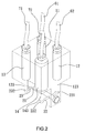
- the body 10 is a rectangular body and has four cylinders 11, 12, 13, 14 located between the top and the bottom thereof.
- the four cylinders 11, 12, 13, 14 are respectively connected to the left brake lever hose 61, the right brake lever hose 62, the front wheel brake hose 71 and the rear wheel brake hose 72.
- Each of the four cylinders 11, 12, 13, 14 has a movable unit 111/121/131/141 which has a first end located in the cylinder 11/12/13/14 corresponding thereto, and a second end protruding beyond the first end of the cylinder 11/12/13/14 corresponding thereto.
- Each of the movable units 111, 121, 131, 141 is movable relative to the cylinder 11/12/13/14 corresponding thereto axially.
- the movable unit 111/121/131/141 has a piston 112/122/132/142 and a piston rod 113/123/133/143.
- the piston 112/122/132/142 is movably located in the cylinder 11/12/13/14 corresponding thereto, and the piston rod 113/123/133/143 has a first end connected to the piston 112/122/132/142, and a second end protruding beyond the first end of the cylinder 11/12/13/14.
- the transmission device 20 is connected to the connection portion 15 on the bottom of the body 10, and comprises a positioning rod 21, a first link 22 and a second link 23.
- the positioning rod 21 extends through the connection portion 15 and is rotatable along the axis thereof.
- the first and second links 22, 23 respectively extend through the positioning rod 21, and are rotatable with the positioning rod 21.
- a driving end 221 and a passive end 222 are connected to the two ends of the first link 22, and are respectively located on the two movement tracks of the two piston rods 123, 143 connected to the two cylinders 12, 14 which are connected to the right brake lever hose 62 and the rear wheel brake hose 72.
- the other driving end 231 and the other passive end 232 are connected to the two ends of the second link 23, and are respectively located on the two movement tracks of the two piston rods 113, 133 connected to the two cylinders 11, 13 which are connected to the left brake lever hose 61 and the front wheel brake hose 71.
- the first link 22 is activated by the positioning rod 21, and is rotated along with the second link 23 so that the passive end 222 pushes the piston rod 143.
- the two piston rods 133, 143 move the pistons 132, 142 to drive the front wheel brake unit and the rear wheel brake unit via the front and rear wheel brake hoses 71, 72.
- the first link 22 rotates the positioning rod 21 and drives the second link 23 so as to drive the front wheel brake unit and the rear wheel brake unit via the front and rear wheel brake hoses 71, 72.
- the present invention is easily operated and can activate the front wheel brake unit and the rear wheel brake unit by either pulling the left or right brake lever.
- the transmission device 20 is replaced by the transmission device 30 which has a positioning rod 31, a first link 32 and a second link 33.
- the central portion of the positioning rod 31 is connected to the connection portion 16 located at the bottom of the body 10 and is secured by a positioning shaft 161, so that the positioning rod 31 is rotatable about the positioning shaft 161.
- the first and second links 32, 33 are respectively connected to the two ends of the positioning rod 31.
- the two driving ends 321, 322 are located on two ends of the first link 32 and located on the movement tracks of the two protruding piston rods 113, 123.
- the two passive ends 331, 332 are located on two ends of the second link 33, and located on the movement tracks of the two protruding piston rods 133, 143.
- the two passive ends 331, 332 simultaneously push the piston rods 133, 143 and the two pistons 132, 142 so as to drive the front wheel brake unit and the rear wheel brake unit via the front and rear wheel brake hoses 71, 72.
- the piston 122 and the piston rod 123 of the cylinder 12 are driven via the hydraulic power from the right brake lever hose 62.
- the first link 32 is moved downward and the second link 33 on the other end of the positioning rod 31 is moved upward.
- the two passive ends 331, 332 simultaneously push the piston rods 133, 143 and the two pistons 132, 142 so as to drive the front wheel brake unit and the rear wheel brake unit via the front and rear wheel brake hoses 71, 72.
- the left and right brake lever hoses 61, 62 and the front and rear wheel brake hoses 71, 72 are connected to the same side of the body 10, by the cooperation of the transmission devices 20, 30 on the other side of the body 10, using the leverage principle, when the driving ends 221(231), 321 (322) is moved downward, the two passive ends 222, 232, 331, 332 are moved upward by the positioning rods 21, 31 to achieve the safe braking action.
- the four hoses are connected to the same side of the body 10 and this is difficult when installed to the vehicle.
- the applicant further provides an improved arrangement as shown in Figs. 11 to 15 , the left and right brake lever hoses 61, 62 and the front and rear wheel brake hoses 71, 72 are respectively connected to the two opposite sides of the body 50, which is more convenient when in use.
- the third embodiment of the auxiliary device 1 of the present invention comprises a body 50 and a transmission device 40, wherein the body 50 is a rectangular body and has four cylinders 51, 52, 53, 54 located between the top and the bottom thereof.
- the two cylinders 51, 52 on the top of the body 50 are connected to the left and right brake lever hoses 61, 62, and the other two cylinders 53, 54 on the bottom of the body 50 are connected to the front and rear wheel brake hoses 71, 72.
- Each of the cylinders 51, 52, 53, 54 has a movable unit 511/521/531/541 which has a piston 512/522/532/542 and a piston rod 513/523/533/543.
- the piston 512/522/532/542 is movably located in the cylinder 51/52/53/54 corresponding thereto.
- the piston rod 513/523/533/543 is connected to the piston 512/522/532/542 correspondingly and protrudes beyond the cylinder 51/52/53/54 corresponding thereto and located in opposite to the hose.
- the piston rods 513, 523 of the cylinders 51, 52 that are connected to the left and right brake lever hoses 61, 62, extend beyond the bottom of the body 50.
- the piston rods 533, 543 of the cylinders 53, 54 that are connected to the front and rear wheel brake hoses 71, 72, extend beyond the top of the body 50.
- the transmission device 40 of the embodiment has a positioning rod 41, a first link 42 and a second link 43.
- the positioning rod 41 extends through the body 50 and the two ends of the positioning rod 41 respectively extend beyond the top and bottom of the body 50.
- the two ends of the positioning rod 41 are respectively connected to the first and second links 42, 43.
- the two driving ends 421, 422 are located on the two ends of the first link 42 and located on the movement tracks of the two protruding piston rods 513, 523.
- the two passive ends 431, 432 are located on the two ends of the second link 43, and located on the movement tracks of the two protruding piston rods 533, 543.
- the two passive ends 431, 432 simultaneously push the piston rods 533, 543 and the two pistons 532, 542 so as to drive the front wheel brake unit and the rear wheel brake unit via the front and rear wheel brake hoses 71, 72.
- the piston 522 and the piston rod 523 of the cylinder 52 are driven via the hydraulic power from the right brake lever hose 62.
- the first link 42 is moved downward, and the positioning rod 41 and the second link 43 are moved downward.
- the two passive ends 431, 432 simultaneously push the piston rods 533, 543 and the two pistons 532, 542 so as to drive the front wheel brake unit and the rear wheel brake unit via the front and rear wheel brake hoses 71, 72.
- the driving ends 221, 231, 321, 322, 421, 422 are located in the cylinders 12, 11, 11, 12, 51, 52 which has limited amount or even no hydraulic oil when the brake lever is not pulled.
- the hydraulic oil is full to have the best status for the braking actions.
- the front and wheel are braked by either pulling the left brake lever or the right brake lever.
- the front wheel brake unit and the rear wheel brake unit are simultaneously activated by pulling either the left brake lever or the right break lever.
- the front wheel brake unit and the rear wheel brake unit are simultaneously activated by pulling either the left brake lever or the right break lever.
- the front wheel brake unit and the rear wheel brake unit preferably, the front wheel is braked right after the rear wheel is braked.
- the braking force applied to the rear wheel is larger than that to the front wheel.
- the diameters of the cylinders 14, 54 connected to the rear wheel brake hose 72 are larger than those of the diameters of the cylinders 13, 53 connected to the front wheel brake hose 71, this is helpful for the control to the vehicle when the rider brakes the vehicle.
Landscapes
- Engineering & Computer Science (AREA)
- Mechanical Engineering (AREA)
- Physics & Mathematics (AREA)
- Fluid Mechanics (AREA)
- Transportation (AREA)
- Transmission Of Braking Force In Braking Systems (AREA)
Abstract
Description
- The present invention relates to an auxiliary device for a brake assembly, and more particularly, to auxiliary device for a hydraulic brake assembly of a two-wheel vehicle to simultaneously activate the front and rear wheel brake units and control the difference of the braking pressures of the front and rear wheels.
- For two-wheel vehicles, such as bicycles or motorbikes, are used widely as a convenient transportation tool. In order to increase the efficiency of braking feature, the hydraulic brake assembly is developed and becomes the main trend of the brake systems.
- The conventional brake assembly for two-wheel vehicles uses the left brake lever and the right brake lever to respectively brake the front wheel and the rear wheel. However, some of the riders may brake the front wheel or the rear wheel too much so that the front or rear wheel is locked when in urgent situations, this situation may cause the eider and the bicycle to flip over or slip aside, and the rider or people beside the rider may be injured. Preferably, when braking the bicycle, the rear wheel is first braked and the front wheel is then braked. Preferably, 30% of the braking force is applied to the front wheel and 70% of the braking force is applied to the rear wheel.
- The hydraulic brake assembly has higher efficiency than the conventional brake assembly, especially for those high-end bicycles and motorbikes, a reliable and high performance brake assembly is required. However, when in urgent situations, such as moving downward at high speed, the improper operation to the hydraulic brake assembly, such as the braking force to the rear wheel is larger than that to the front wheel, may cause damage to the bicycle or motorbike, and the rider.
- The present invention intends to provide an auxiliary device for a hydraulic brake assembly which improves the shortcomings mentioned above.
- The present invention relates to an auxiliary device for a hydraulic brake assembly and comprises a body having four cylinders located between the top and the bottom thereof, each of the four cylinders has a movable unit. The movable unit has its first end located in the cylinder, and the second end protruding beyond the first end of the cylinder and each of the movable units is movable relative to the cylinder axially. A transmission device is disposed on the body and has two driving ends and two passive ends, the two driving ends and the two passive ends are respectively located on movement tracks of the four movable units and contact the four movable units. When the movable unit drives one of the driving ends located corresponding thereto, the two movable units located corresponding to the passive ends are moved by the transmission device.
- Preferably, the movable unit has a piston and a piston rod. The piston is movably located in the cylinder corresponding thereto, and the piston rod has the first end thereof connected to the piston, and the second end protruding beyond the first end of the cylinder and contacting one of the driving ends, or one of the passive ends of the transmission device. By the cooperation of the pistons and the piston rods, the present invention can control the braking actions.
- Preferably, the left brake lever hose and the right brake lever hose are respectively connected to two respective second ends of the cylinders located corresponding to the two driving ends. The front wheel brake hose and the rear wheel brake hose are respectively connected to two respective second ends of the cylinders located corresponding to the two passive ends.
- Preferably, the diameter of the cylinder connected to the rear wheel brake hose is larger than the diameter of the cylinder connected with the front wheel brake hose.
- Preferably, the piston rods protruding from the cylinders are located on one side of the body, and a connection portion is connected to the side of the body so as to be connected with the transmission device.
- Preferably, the transmission device has a positioning rod, a first link and a second link. The positioning rod extends through the connection portion and is rotatable along the axis thereof. The first and second links respectively extend through the positioning rods. The two driving ends are located on two respective first ends of the first and second links, the two passive ends are located on two respective second ends of the first and second links.
- Preferably, the transmission device has a positioning rod, a first link and a second link. The central portion of the positioning rod is connected to the connection portion. Two ends of the positioning rod are rotatable about the connection portion. The first and second links are respectively connected to the two ends of the positioning rod. The two driving ends are located on two ends of the first link. The two passive ends are located on two ends of the first and second link.
- Preferably, the piston rods that are located corresponding to the two driving ends protrude from the first side of the body. The piston rods that are located corresponding to the two passive ends protrude from the second side of the body. The transmission device extends through the body, and the two driving ends and the two passive ends are respectively located on two opposite sides of the body.
- Preferably, the transmission device has a positioning rod, a first link and a second link. The positioning rod extends through the body. The first and second links are respectively connected to two ends of the positioning rods. The two driving ends are located on two ends of the first link. The two passive ends are located on two ends of the second links.
- The primary object of the present invention is to provide an auxiliary device for a hydraulic brake assembly. The front and wheel are braked by either pulling the left brake lever or the right brake lever.
- Another object of the present invention is to provide an auxiliary device for a hydraulic brake assembly, wherein the force applied to the rear wheel is always larger than that to the front wheel.
- The present invention will become more obvious from the following description when taken in connection with the accompanying drawings which show, for purposes of illustration only, a preferred embodiment in accordance with the present invention.
-
-
Fig. 1 is a perspective view to show the auxiliary device of the present invention; -
Fig. 2 shows the inside arrangement of the auxiliary device of the present invention; -
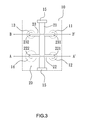
Fig. 3 is a top view to show the arrangement of the auxiliary device of the present invention; -
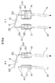
Fig. 4 is two cross sectional views respectively taking along lines A-A' and B-B' inFig. 3 , wherein no action is taken; -
Fig. 5 is two cross sectional views respectively taking along lines A-A' and B-B' inFig. 3 , wherein the left brake lever is operated; -
Fig. 6 is two cross sectional views respectively taking along lines A-A' and B-B' inFig. 3 , wherein the right brake lever is operated; -
Fig. 7 is a top view to show the arrangement of the second embodiment of the auxiliary device of the present invention; -
Fig. 8 is two cross sectional views respectively taking along lines C-C' and D-D' inFig. 7 , wherein no action is taken; -
Fig. 9 is two cross sectional views respectively taking along lines C-C' and D-D' inFig. 7 , wherein the left brake lever is operated; -
Fig. 10 is two cross sectional views respectively taking along lines C-C' and D-D' inFig. 7 , wherein the right brake lever is operated; -
Fig. 11 shows the arrangement of the third embodiment of the auxiliary device of the present invention; -
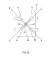
Fig. 12 is a top view to show the arrangement of the third embodiment of the auxiliary device of the present invention; -
Fig. 13 is two cross sectional views respectively taking along lines E-E' and F-F' inFig. 11 , wherein no action is taken; -
Fig. 14 is two cross sectional views respectively taking along lines E-E' and F-F' inFig. 11 , wherein the left brake lever is operated, and -
Fig. 15 is two cross sectional views respectively taking along lines E-E' and F-F' inFig. 11 , wherein the right brake lever is operated. - Referring to
Figs. 1 to 6 , theauxiliary device 1 of a hydraulic brake assembly for two-wheel vehicles of the present invention is connected to the leftbrake lever hose 61, the rightbrake lever hose 62, the frontwheel brake hose 71 and the rearwheel brake hose 72 of the two-wheel vehicle. Theauxiliary device 1 comprises abody 10 and atransmission device 20. - As shown in
Figs. 2 to 4 , thebody 10 is a rectangular body and has fourcylinders cylinders brake lever hose 61, the rightbrake lever hose 62, the frontwheel brake hose 71 and the rearwheel brake hose 72. Each of the fourcylinders movable unit 111/121/131/141 which has a first end located in thecylinder 11/12/13/14 corresponding thereto, and a second end protruding beyond the first end of thecylinder 11/12/13/14 corresponding thereto., Each of themovable units cylinder 11/12/13/14 corresponding thereto axially. Themovable unit 111/121/131/141 has apiston 112/122/132/142 and apiston rod 113/123/133/143. Thepiston 112/122/132/142 is movably located in thecylinder 11/12/13/14 corresponding thereto, and thepiston rod 113/123/133/143 has a first end connected to thepiston 112/122/132/142, and a second end protruding beyond the first end of thecylinder 11/12/13/14. - The
transmission device 20 is connected to theconnection portion 15 on the bottom of thebody 10, and comprises apositioning rod 21, afirst link 22 and asecond link 23. Thepositioning rod 21 extends through theconnection portion 15 and is rotatable along the axis thereof. The first andsecond links positioning rod 21, and are rotatable with thepositioning rod 21. A drivingend 221 and apassive end 222 are connected to the two ends of thefirst link 22, and are respectively located on the two movement tracks of the twopiston rods cylinders brake lever hose 62 and the rearwheel brake hose 72. The other drivingend 231 and the otherpassive end 232 are connected to the two ends of thesecond link 23, and are respectively located on the two movement tracks of the twopiston rods cylinders brake lever hose 61 and the frontwheel brake hose 71. - When the left and right
brake lever hoses Fig. 4 , the driving ends 221, 231 contact thepiston rods piston rods Fig. 5 , thepiston 112 and thepiston rod 113 of thecylinder 11 are driven via the hydraulic power from the leftbrake lever hose 61, thesecond link 23 is pushed by the drivingend 231 and thepositioning rod 21 is rotated so as to drive thepassive end 232 to push thepiston rod 133. In the meanwhile, thefirst link 22 is activated by thepositioning rod 21, and is rotated along with thesecond link 23 so that thepassive end 222 pushes thepiston rod 143. The twopiston rods pistons wheel brake hoses Fig. 6 , thefirst link 22 rotates thepositioning rod 21 and drives thesecond link 23 so as to drive the front wheel brake unit and the rear wheel brake unit via the front and rearwheel brake hoses - The present invention is easily operated and can activate the front wheel brake unit and the rear wheel brake unit by either pulling the left or right brake lever.
- As shown in
Figs. 7 to 10 , by different connection between the parts of the present invention, the same function is achieved. Thetransmission device 20 is replaced by thetransmission device 30 which has apositioning rod 31, afirst link 32 and asecond link 33. The central portion of thepositioning rod 31 is connected to theconnection portion 16 located at the bottom of thebody 10 and is secured by apositioning shaft 161, so that thepositioning rod 31 is rotatable about thepositioning shaft 161. The first andsecond links positioning rod 31. The two driving ends 321, 322 are located on two ends of thefirst link 32 and located on the movement tracks of the two protrudingpiston rods passive ends second link 33, and located on the movement tracks of the two protrudingpiston rods - As shown in
Figs. 8 to 10 , when no braking action is taken, as shown inFig. 8 , two driving ends 321, 322 and the passive ends 331, 332 respectively contact thepiston rods Fig. 9 , thepiston 112 and thepiston rod 113 of thecylinder 11 are driven via the hydraulic power from the leftbrake lever hose 61, thefirst link 32 is pushed by the drivingend 321 and thefirst link 32 is moved downward, thepositioning rod 31 is rotated about theconnection portion 16 so that thesecond link 33 on the opposite side of thepositioning rod 31 moves upward. The twopassive ends piston rods pistons wheel brake hoses Fig. 10 , thepiston 122 and thepiston rod 123 of thecylinder 12 are driven via the hydraulic power from the rightbrake lever hose 62. Thefirst link 32 is moved downward and thesecond link 33 on the other end of thepositioning rod 31 is moved upward. The twopassive ends piston rods pistons wheel brake hoses - In the previous two embodiments, the left and right
brake lever hoses wheel brake hoses body 10, by the cooperation of thetransmission devices body 10, using the leverage principle, when the driving ends 221(231), 321 (322) is moved downward, the twopassive ends positioning rods body 10 and this is difficult when installed to the vehicle. The applicant further provides an improved arrangement as shown inFigs. 11 to 15 , the left and rightbrake lever hoses wheel brake hoses body 50, which is more convenient when in use. - As shown in
Figs. 11 to 13 , the third embodiment of theauxiliary device 1 of the present invention comprises abody 50 and atransmission device 40, wherein thebody 50 is a rectangular body and has fourcylinders cylinders body 50 are connected to the left and rightbrake lever hoses cylinders body 50 are connected to the front and rearwheel brake hoses cylinders movable unit 511/521/531/541 which has apiston 512/522/532/542 and apiston rod 513/523/533/543. Thepiston 512/522/532/542 is movably located in thecylinder 51/52/53/54 corresponding thereto. Thepiston rod 513/523/533/543 is connected to thepiston 512/522/532/542 correspondingly and protrudes beyond thecylinder 51/52/53/54 corresponding thereto and located in opposite to the hose. Thepiston rods cylinders brake lever hoses body 50. Thepiston rods cylinders wheel brake hoses body 50. - The
transmission device 40 of the embodiment has apositioning rod 41, afirst link 42 and asecond link 43. Thepositioning rod 41 extends through thebody 50 and the two ends of thepositioning rod 41 respectively extend beyond the top and bottom of thebody 50. The two ends of thepositioning rod 41 are respectively connected to the first andsecond links first link 42 and located on the movement tracks of the two protrudingpiston rods passive ends second link 43, and located on the movement tracks of the two protrudingpiston rods - As shown in
Figs. 13 to 15 , when no braking action is taken, as shown inFig. 13 , two driving ends 421, 422 and the passive ends 431, 432 respectively contact thepiston rods Fig. 14 , thepiston 512 and thepiston rod 513 of thecylinder 51 are driven via the hydraulic power from the leftbrake lever hose 61, thefirst link 42 is pushed by the drivingend 421 and thefirst link 42 is moved downward, thepositioning rod 41 and thesecond link 43 are moved downward. The twopassive ends piston rods pistons wheel brake hoses Fig. 15 , thepiston 522 and thepiston rod 523 of thecylinder 52 are driven via the hydraulic power from the rightbrake lever hose 62. Thefirst link 42 is moved downward, and thepositioning rod 41 and thesecond link 43 are moved downward. The twopassive ends piston rods pistons wheel brake hoses - For each of the embodiments, the driving ends 221, 231, 321, 322, 421, 422 are located in the
cylinders cylinders - For the
auxiliary device 1 of the present invention, the front and wheel are braked by either pulling the left brake lever or the right brake lever. In detail, the front wheel brake unit and the rear wheel brake unit are simultaneously activated by pulling either the left brake lever or the right break lever. By using different sizes of the front wheel brake unit and the rear wheel brake unit, preferably, the front wheel is braked right after the rear wheel is braked. The braking force applied to the rear wheel is larger than that to the front wheel. In the embodiments, the diameters of thecylinders wheel brake hose 72 are larger than those of the diameters of thecylinders wheel brake hose 71, this is helpful for the control to the vehicle when the rider brakes the vehicle. - While we have shown and described the embodiment in accordance with the present invention, it should be clear to those skilled in the art that further embodiments may be made without departing from the scope of the present invention.
Claims (15)
- An auxiliary device for a hydraulic brake assembly, comprising:a body having four cylinders located between a top and a bottom thereof, each of the four cylinders having a movable unit, each of the movable units having a first end located in the cylinder corresponding thereto and a second end protruding beyond a first end of the cylinder corresponding thereto, and each of the movable units movable relative to the cylinder corresponding thereto axially;a transmission device disposed on the body and having two driving ends and two passive ends, the two driving ends and the two passive ends respectively located on movement tracks of the four movable units and contacting the four movable units, andwhen the movable unit drives one of the driving ends located corresponding thereto, the two movable units located corresponding to the passive ends are moved by the transmission device.
- The device as claimed in claim 1, wherein the movable unit has a piston and a piston rod, the piston is movably located in the cylinder corresponding thereto, the piston rod has a first end connected to the piston, and a second end protruding beyond the first end of the cylinder and contacting one of the driving ends or one of the passive ends of the transmission device.
- The device as claimed in claim 2, wherein a left brake lever hose and a right brake lever hose are respectively connected to two respective second ends of the cylinders located corresponding to the two driving ends, a front wheel brake hose and a rear wheel brake hose are respectively connected to two respective second ends of the cylinders located corresponding to the two passive ends.
- The device as claimed in claim 2, wherein a diameter of the cylinder connected to the rear wheel brake hose is larger than a diameter of the cylinder connected with the front wheel brake hose.
- The device as claimed in claim 4, wherein the piston rods protruding from the cylinders are located on one side of the body, a connection portion is formed on the side of the body so as to be connected with the transmission device.
- The device as claimed in claim 5, wherein the transmission device has a positioning rod, a first link and a second link, the positioning rod extends through the connection portion and is rotatable along an axis thereof, the first and second links respectively extend through the positioning rods, the two driving ends are located on two respective first ends of the first and second links, the two passive ends are located on two respective second ends of the first and second links.
- The device as claimed in claim 5, wherein the transmission device has a positioning rod, a first link and a second link, a central portion of the positioning rod is connected to the connection portion, two ends of the positioning rod are rotatable about the connection portion, the first and second links are respectively connected to the two ends of the positioning rod, the two driving ends are located on two ends of the first link, the two passive ends are located on two ends of the second link.
- The device as claimed in claim 4, wherein the piston rods that are located corresponding to the two driving ends protrude from a first side of the body, the piston rods that are located corresponding to the two passive ends protrude from a second side of the body, the transmission device extends through the body, and the two driving ends and the two passive ends are respectively located on two opposite sides of the body.
- The device as claimed in claim 8, wherein the transmission device has a positioning rod, a first link and a second link, the positioning rod extends through the body, the first and second links are respectively connected to two ends of the positioning rods, the two driving ends are located on two ends of the first link, the two passive ends are located on two ends of the second link.
- The device as claimed in claim 3, wherein a diameter of the cylinder connected to the rear wheel brake hose is larger than a diameter of the cylinder connected with the front wheel brake hose.
- The device as claimed in claim 10, wherein the piston rods protruding from the cylinders are located on one side of the body, a connection portion is formed on the side of the body so as to be connected with the transmission device.
- The device as claimed in claim 11, wherein the transmission device has a positioning rod, a first link and a second link, the positioning rod extends through the connection portion and is rotatable along an axis thereof, the first and second links respectively extend through the positioning rods, the two driving ends are located on two respective first ends of the first and second links, the two passive ends are located on two respective second ends of the first and second links.
- The device as claimed in claim 11, wherein the transmission device has a positioning rod, a first link and a second link, a central portion of the positioning rod is connected to the connection portion, two ends of the positioning rod are rotatable about the connection portion, the first and second links are respectively connected to the two ends of the positioning rod, the two driving ends are located on two ends of the first link, the two passive ends are located on two ends of the second link.
- The device as claimed in claim 10, wherein the piston rods that are located corresponding to the two driving ends protrude from a first side of the body, the piston rods that are located corresponding to the two passive ends protrude from a second side of the body, the transmission device extends through the body, and the two driving ends and the two passive ends are respectively located on two opposite sides of the body.
- The device as claimed in claim 14, wherein the transmission device has a positioning rod, a first link and a second link, the positioning rod extends through the body, the first and second links are respectively connected to two ends of the positioning rods, the two driving ends are located on two ends of the first link, the two passive ends are located on two ends of the second link.
Priority Applications (1)
| Application Number | Priority Date | Filing Date | Title |
|---|---|---|---|
| EP14151492.7A EP2896554B1 (en) | 2014-01-16 | 2014-01-16 | Auxiliary device for hydraulic brake assembly |
Applications Claiming Priority (1)
| Application Number | Priority Date | Filing Date | Title |
|---|---|---|---|
| EP14151492.7A EP2896554B1 (en) | 2014-01-16 | 2014-01-16 | Auxiliary device for hydraulic brake assembly |
Publications (2)
| Publication Number | Publication Date |
|---|---|
| EP2896554A1 true EP2896554A1 (en) | 2015-07-22 |
| EP2896554B1 EP2896554B1 (en) | 2017-03-15 |
Family
ID=49920300
Family Applications (1)
| Application Number | Title | Priority Date | Filing Date |
|---|---|---|---|
| EP14151492.7A Not-in-force EP2896554B1 (en) | 2014-01-16 | 2014-01-16 | Auxiliary device for hydraulic brake assembly |
Country Status (1)
| Country | Link |
|---|---|
| EP (1) | EP2896554B1 (en) |
Cited By (1)
| Publication number | Priority date | Publication date | Assignee | Title |
|---|---|---|---|---|
| WO2017211347A1 (en) * | 2016-06-08 | 2017-12-14 | Schaeffler Technologies AG & Co. KG | Brake system for a vehicle, and vehicle having the brake system |
Citations (3)
| Publication number | Priority date | Publication date | Assignee | Title |
|---|---|---|---|---|
| JP2000280886A (en) * | 1999-03-31 | 2000-10-10 | Nissin Kogyo Co Ltd | Hydraulic bar handle vehicle brake system |
| US20030201667A1 (en) * | 2002-04-29 | 2003-10-30 | Chih-Chen Juan | Hydraulic balanced braking system |
| EP2639123A1 (en) * | 2012-03-16 | 2013-09-18 | Ansure, Inc. | Brake auxiliary device |
-
2014
- 2014-01-16 EP EP14151492.7A patent/EP2896554B1/en not_active Not-in-force
Patent Citations (3)
| Publication number | Priority date | Publication date | Assignee | Title |
|---|---|---|---|---|
| JP2000280886A (en) * | 1999-03-31 | 2000-10-10 | Nissin Kogyo Co Ltd | Hydraulic bar handle vehicle brake system |
| US20030201667A1 (en) * | 2002-04-29 | 2003-10-30 | Chih-Chen Juan | Hydraulic balanced braking system |
| EP2639123A1 (en) * | 2012-03-16 | 2013-09-18 | Ansure, Inc. | Brake auxiliary device |
Cited By (1)
| Publication number | Priority date | Publication date | Assignee | Title |
|---|---|---|---|---|
| WO2017211347A1 (en) * | 2016-06-08 | 2017-12-14 | Schaeffler Technologies AG & Co. KG | Brake system for a vehicle, and vehicle having the brake system |
Also Published As
| Publication number | Publication date |
|---|---|
| EP2896554B1 (en) | 2017-03-15 |
Similar Documents
| Publication | Publication Date | Title |
|---|---|---|
| CN107645998B (en) | Combined brake device for vehicles | |
| CN104210981A (en) | Automatic brake device and automatic brake method of automobile capstan | |
| EP3495254B1 (en) | Hydraulic time difference-based braking device | |
| RU2712208C1 (en) | System of safe braking with double clutch | |
| DE102018125566A1 (en) | BRAKING DEVICE AND BRAKING SYSTEM | |
| ITBO20080651A1 (en) | BRAKING SYSTEM OF A VEHICLE ACTING TO COMMAND A REGENERATIVE BRAKING | |
| JP6300894B2 (en) | Hydraulic time difference brake device | |
| TWI638742B (en) | Integrated drive for bicycle handlebars | |
| CN201800698U (en) | Driving and parking brake device of all-terrain vehicle | |
| US9227693B2 (en) | Auxiliary device for hydraulic brake assembly | |
| EP2896554B1 (en) | Auxiliary device for hydraulic brake assembly | |
| CN103303295A (en) | Brake of vehicle | |
| CN205345257U (en) | Manual brake system is united to dish behind preceding dish | |
| TWI637871B (en) | Hydraulic braking system and control device thereof | |
| CN103448705A (en) | Brake master cylinder assembly | |
| CN103925318B (en) | Normally closed parking brake | |
| CN106608252A (en) | Hydraulic time difference brake device | |
| CN207315929U (en) | A kind of sprocket-type brake | |
| US20150075920A1 (en) | Brake Release System | |
| US3692147A (en) | Brake system using vehicle's own kinetic energy to control the brake and the device thereof | |
| TWI489045B (en) | Hydraulic brake assist device | |
| CN103723229B (en) | Electric vehicle mechanical disc brake mechanism | |
| JP2004217211A (en) | Disc brakes for vehicles | |
| CN209870656U (en) | Linkage brake mechanism and brake system thereof | |
| CN201506442U (en) | Synchronous braking device |
Legal Events
| Date | Code | Title | Description |
|---|---|---|---|
| PUAI | Public reference made under article 153(3) epc to a published international application that has entered the european phase |
Free format text: ORIGINAL CODE: 0009012 |
|
| 17P | Request for examination filed |
Effective date: 20140116 |
|
| AK | Designated contracting states |
Kind code of ref document: A1 Designated state(s): AL AT BE BG CH CY CZ DE DK EE ES FI FR GB GR HR HU IE IS IT LI LT LU LV MC MK MT NL NO PL PT RO RS SE SI SK SM TR |
|
| AX | Request for extension of the european patent |
Extension state: BA ME |
|
| 17P | Request for examination filed |
Effective date: 20160122 |
|
| RBV | Designated contracting states (corrected) |
Designated state(s): AL AT BE BG CH CY CZ DE DK EE ES FI FR GB GR HR HU IE IS IT LI LT LU LV MC MK MT NL NO PL PT RO RS SE SI SK SM TR |
|
| GRAP | Despatch of communication of intention to grant a patent |
Free format text: ORIGINAL CODE: EPIDOSNIGR1 |
|
| RIC1 | Information provided on ipc code assigned before grant |
Ipc: B62L 3/08 20060101AFI20160809BHEP Ipc: B60T 8/26 20060101ALN20160809BHEP |
|
| INTG | Intention to grant announced |
Effective date: 20160902 |
|
| RIN1 | Information on inventor provided before grant (corrected) |
Inventor name: TSENG, TON-RONG |
|
| GRAS | Grant fee paid |
Free format text: ORIGINAL CODE: EPIDOSNIGR3 |
|
| GRAA | (expected) grant |
Free format text: ORIGINAL CODE: 0009210 |
|
| AK | Designated contracting states |
Kind code of ref document: B1 Designated state(s): AL AT BE BG CH CY CZ DE DK EE ES FI FR GB GR HR HU IE IS IT LI LT LU LV MC MK MT NL NO PL PT RO RS SE SI SK SM TR |
|
| REG | Reference to a national code |
Ref country code: CH Ref legal event code: EP Ref country code: GB Ref legal event code: FG4D |
|
| REG | Reference to a national code |
Ref country code: IE Ref legal event code: FG4D |
|
| REG | Reference to a national code |
Ref country code: AT Ref legal event code: REF Ref document number: 875230 Country of ref document: AT Kind code of ref document: T Effective date: 20170415 |
|
| REG | Reference to a national code |
Ref country code: DE Ref legal event code: R096 Ref document number: 602014007490 Country of ref document: DE |
|
| REG | Reference to a national code |
Ref country code: NL Ref legal event code: FP |
|
| REG | Reference to a national code |
Ref country code: LT Ref legal event code: MG4D |
|
| PG25 | Lapsed in a contracting state [announced via postgrant information from national office to epo] |
Ref country code: FI Free format text: LAPSE BECAUSE OF FAILURE TO SUBMIT A TRANSLATION OF THE DESCRIPTION OR TO PAY THE FEE WITHIN THE PRESCRIBED TIME-LIMIT Effective date: 20170315 Ref country code: HR Free format text: LAPSE BECAUSE OF FAILURE TO SUBMIT A TRANSLATION OF THE DESCRIPTION OR TO PAY THE FEE WITHIN THE PRESCRIBED TIME-LIMIT Effective date: 20170315 Ref country code: GR Free format text: LAPSE BECAUSE OF FAILURE TO SUBMIT A TRANSLATION OF THE DESCRIPTION OR TO PAY THE FEE WITHIN THE PRESCRIBED TIME-LIMIT Effective date: 20170616 Ref country code: LT Free format text: LAPSE BECAUSE OF FAILURE TO SUBMIT A TRANSLATION OF THE DESCRIPTION OR TO PAY THE FEE WITHIN THE PRESCRIBED TIME-LIMIT Effective date: 20170315 Ref country code: NO Free format text: LAPSE BECAUSE OF FAILURE TO SUBMIT A TRANSLATION OF THE DESCRIPTION OR TO PAY THE FEE WITHIN THE PRESCRIBED TIME-LIMIT Effective date: 20170615 |
|
| REG | Reference to a national code |
Ref country code: AT Ref legal event code: MK05 Ref document number: 875230 Country of ref document: AT Kind code of ref document: T Effective date: 20170315 |
|
| PG25 | Lapsed in a contracting state [announced via postgrant information from national office to epo] |
Ref country code: RS Free format text: LAPSE BECAUSE OF FAILURE TO SUBMIT A TRANSLATION OF THE DESCRIPTION OR TO PAY THE FEE WITHIN THE PRESCRIBED TIME-LIMIT Effective date: 20170315 Ref country code: LV Free format text: LAPSE BECAUSE OF FAILURE TO SUBMIT A TRANSLATION OF THE DESCRIPTION OR TO PAY THE FEE WITHIN THE PRESCRIBED TIME-LIMIT Effective date: 20170315 Ref country code: BG Free format text: LAPSE BECAUSE OF FAILURE TO SUBMIT A TRANSLATION OF THE DESCRIPTION OR TO PAY THE FEE WITHIN THE PRESCRIBED TIME-LIMIT Effective date: 20170615 Ref country code: SE Free format text: LAPSE BECAUSE OF FAILURE TO SUBMIT A TRANSLATION OF THE DESCRIPTION OR TO PAY THE FEE WITHIN THE PRESCRIBED TIME-LIMIT Effective date: 20170315 |
|
| PG25 | Lapsed in a contracting state [announced via postgrant information from national office to epo] |
Ref country code: AT Free format text: LAPSE BECAUSE OF FAILURE TO SUBMIT A TRANSLATION OF THE DESCRIPTION OR TO PAY THE FEE WITHIN THE PRESCRIBED TIME-LIMIT Effective date: 20170315 Ref country code: CZ Free format text: LAPSE BECAUSE OF FAILURE TO SUBMIT A TRANSLATION OF THE DESCRIPTION OR TO PAY THE FEE WITHIN THE PRESCRIBED TIME-LIMIT Effective date: 20170315 Ref country code: ES Free format text: LAPSE BECAUSE OF FAILURE TO SUBMIT A TRANSLATION OF THE DESCRIPTION OR TO PAY THE FEE WITHIN THE PRESCRIBED TIME-LIMIT Effective date: 20170315 Ref country code: RO Free format text: LAPSE BECAUSE OF FAILURE TO SUBMIT A TRANSLATION OF THE DESCRIPTION OR TO PAY THE FEE WITHIN THE PRESCRIBED TIME-LIMIT Effective date: 20170315 Ref country code: SK Free format text: LAPSE BECAUSE OF FAILURE TO SUBMIT A TRANSLATION OF THE DESCRIPTION OR TO PAY THE FEE WITHIN THE PRESCRIBED TIME-LIMIT Effective date: 20170315 Ref country code: EE Free format text: LAPSE BECAUSE OF FAILURE TO SUBMIT A TRANSLATION OF THE DESCRIPTION OR TO PAY THE FEE WITHIN THE PRESCRIBED TIME-LIMIT Effective date: 20170315 |
|
| PG25 | Lapsed in a contracting state [announced via postgrant information from national office to epo] |
Ref country code: PL Free format text: LAPSE BECAUSE OF FAILURE TO SUBMIT A TRANSLATION OF THE DESCRIPTION OR TO PAY THE FEE WITHIN THE PRESCRIBED TIME-LIMIT Effective date: 20170315 Ref country code: PT Free format text: LAPSE BECAUSE OF FAILURE TO SUBMIT A TRANSLATION OF THE DESCRIPTION OR TO PAY THE FEE WITHIN THE PRESCRIBED TIME-LIMIT Effective date: 20170717 Ref country code: IS Free format text: LAPSE BECAUSE OF FAILURE TO SUBMIT A TRANSLATION OF THE DESCRIPTION OR TO PAY THE FEE WITHIN THE PRESCRIBED TIME-LIMIT Effective date: 20170715 Ref country code: SM Free format text: LAPSE BECAUSE OF FAILURE TO SUBMIT A TRANSLATION OF THE DESCRIPTION OR TO PAY THE FEE WITHIN THE PRESCRIBED TIME-LIMIT Effective date: 20170315 |
|
| REG | Reference to a national code |
Ref country code: DE Ref legal event code: R097 Ref document number: 602014007490 Country of ref document: DE |
|
| PLBE | No opposition filed within time limit |
Free format text: ORIGINAL CODE: 0009261 |
|
| STAA | Information on the status of an ep patent application or granted ep patent |
Free format text: STATUS: NO OPPOSITION FILED WITHIN TIME LIMIT |
|
| REG | Reference to a national code |
Ref country code: FR Ref legal event code: PLFP Year of fee payment: 5 |
|
| PG25 | Lapsed in a contracting state [announced via postgrant information from national office to epo] |
Ref country code: DK Free format text: LAPSE BECAUSE OF FAILURE TO SUBMIT A TRANSLATION OF THE DESCRIPTION OR TO PAY THE FEE WITHIN THE PRESCRIBED TIME-LIMIT Effective date: 20170315 |
|
| 26N | No opposition filed |
Effective date: 20171218 |
|
| PG25 | Lapsed in a contracting state [announced via postgrant information from national office to epo] |
Ref country code: IT Free format text: LAPSE BECAUSE OF FAILURE TO SUBMIT A TRANSLATION OF THE DESCRIPTION OR TO PAY THE FEE WITHIN THE PRESCRIBED TIME-LIMIT Effective date: 20170315 Ref country code: SI Free format text: LAPSE BECAUSE OF FAILURE TO SUBMIT A TRANSLATION OF THE DESCRIPTION OR TO PAY THE FEE WITHIN THE PRESCRIBED TIME-LIMIT Effective date: 20170315 |
|
| PGFP | Annual fee paid to national office [announced via postgrant information from national office to epo] |
Ref country code: NL Payment date: 20180116 Year of fee payment: 5 |
|
| PGFP | Annual fee paid to national office [announced via postgrant information from national office to epo] |
Ref country code: GB Payment date: 20180108 Year of fee payment: 5 |
|
| PGFP | Annual fee paid to national office [announced via postgrant information from national office to epo] |
Ref country code: FR Payment date: 20180130 Year of fee payment: 5 |
|
| REG | Reference to a national code |
Ref country code: CH Ref legal event code: PL |
|
| PG25 | Lapsed in a contracting state [announced via postgrant information from national office to epo] |
Ref country code: LU Free format text: LAPSE BECAUSE OF NON-PAYMENT OF DUE FEES Effective date: 20180116 |
|
| REG | Reference to a national code |
Ref country code: IE Ref legal event code: MM4A |
|
| REG | Reference to a national code |
Ref country code: BE Ref legal event code: MM Effective date: 20180131 |
|
| PG25 | Lapsed in a contracting state [announced via postgrant information from national office to epo] |
Ref country code: BE Free format text: LAPSE BECAUSE OF NON-PAYMENT OF DUE FEES Effective date: 20180131 Ref country code: CH Free format text: LAPSE BECAUSE OF NON-PAYMENT OF DUE FEES Effective date: 20180131 Ref country code: LI Free format text: LAPSE BECAUSE OF NON-PAYMENT OF DUE FEES Effective date: 20180131 |
|
| PG25 | Lapsed in a contracting state [announced via postgrant information from national office to epo] |
Ref country code: IE Free format text: LAPSE BECAUSE OF NON-PAYMENT OF DUE FEES Effective date: 20180116 |
|
| PGFP | Annual fee paid to national office [announced via postgrant information from national office to epo] |
Ref country code: DE Payment date: 20190125 Year of fee payment: 6 |
|
| PG25 | Lapsed in a contracting state [announced via postgrant information from national office to epo] |
Ref country code: MC Free format text: LAPSE BECAUSE OF FAILURE TO SUBMIT A TRANSLATION OF THE DESCRIPTION OR TO PAY THE FEE WITHIN THE PRESCRIBED TIME-LIMIT Effective date: 20170315 |
|
| REG | Reference to a national code |
Ref country code: NL Ref legal event code: MM Effective date: 20190201 |
|
| GBPC | Gb: european patent ceased through non-payment of renewal fee |
Effective date: 20190116 |
|
| PG25 | Lapsed in a contracting state [announced via postgrant information from national office to epo] |
Ref country code: FR Free format text: LAPSE BECAUSE OF NON-PAYMENT OF DUE FEES Effective date: 20190131 Ref country code: NL Free format text: LAPSE BECAUSE OF NON-PAYMENT OF DUE FEES Effective date: 20190201 |
|
| PG25 | Lapsed in a contracting state [announced via postgrant information from national office to epo] |
Ref country code: GB Free format text: LAPSE BECAUSE OF NON-PAYMENT OF DUE FEES Effective date: 20190116 |
|
| PG25 | Lapsed in a contracting state [announced via postgrant information from national office to epo] |
Ref country code: MT Free format text: LAPSE BECAUSE OF NON-PAYMENT OF DUE FEES Effective date: 20180116 |
|
| PG25 | Lapsed in a contracting state [announced via postgrant information from national office to epo] |
Ref country code: TR Free format text: LAPSE BECAUSE OF FAILURE TO SUBMIT A TRANSLATION OF THE DESCRIPTION OR TO PAY THE FEE WITHIN THE PRESCRIBED TIME-LIMIT Effective date: 20170315 |
|
| PG25 | Lapsed in a contracting state [announced via postgrant information from national office to epo] |
Ref country code: HU Free format text: LAPSE BECAUSE OF FAILURE TO SUBMIT A TRANSLATION OF THE DESCRIPTION OR TO PAY THE FEE WITHIN THE PRESCRIBED TIME-LIMIT; INVALID AB INITIO Effective date: 20140116 Ref country code: MK Free format text: LAPSE BECAUSE OF NON-PAYMENT OF DUE FEES Effective date: 20170315 Ref country code: CY Free format text: LAPSE BECAUSE OF FAILURE TO SUBMIT A TRANSLATION OF THE DESCRIPTION OR TO PAY THE FEE WITHIN THE PRESCRIBED TIME-LIMIT Effective date: 20170315 |
|
| PG25 | Lapsed in a contracting state [announced via postgrant information from national office to epo] |
Ref country code: AL Free format text: LAPSE BECAUSE OF FAILURE TO SUBMIT A TRANSLATION OF THE DESCRIPTION OR TO PAY THE FEE WITHIN THE PRESCRIBED TIME-LIMIT Effective date: 20170315 |
|
| REG | Reference to a national code |
Ref country code: DE Ref legal event code: R119 Ref document number: 602014007490 Country of ref document: DE |
|
| PG25 | Lapsed in a contracting state [announced via postgrant information from national office to epo] |
Ref country code: DE Free format text: LAPSE BECAUSE OF NON-PAYMENT OF DUE FEES Effective date: 20200801 |