EP2896420B1 - Vorrichtung zur nadellosen transdermalen Verabreichung von Arzneimitteln - Google Patents
Vorrichtung zur nadellosen transdermalen Verabreichung von Arzneimitteln Download PDFInfo
- Publication number
- EP2896420B1 EP2896420B1 EP14196904.8A EP14196904A EP2896420B1 EP 2896420 B1 EP2896420 B1 EP 2896420B1 EP 14196904 A EP14196904 A EP 14196904A EP 2896420 B1 EP2896420 B1 EP 2896420B1
- Authority
- EP
- European Patent Office
- Prior art keywords
- plunger
- piston
- nipple
- chamber
- firing
- Prior art date
- Legal status (The legal status is an assumption and is not a legal conclusion. Google has not performed a legal analysis and makes no representation as to the accuracy of the status listed.)
- Active
Links
Images


Classifications
-
- A—HUMAN NECESSITIES
- A61—MEDICAL OR VETERINARY SCIENCE; HYGIENE
- A61M—DEVICES FOR INTRODUCING MEDIA INTO, OR ONTO, THE BODY; DEVICES FOR TRANSDUCING BODY MEDIA OR FOR TAKING MEDIA FROM THE BODY; DEVICES FOR PRODUCING OR ENDING SLEEP OR STUPOR
- A61M5/00—Devices for bringing media into the body in a subcutaneous, intra-vascular or intramuscular way; Accessories therefor, e.g. filling or cleaning devices, arm-rests
- A61M5/178—Syringes
- A61M5/30—Syringes for injection by jet action, without needle, e.g. for use with replaceable ampoules or carpules
-
- A—HUMAN NECESSITIES
- A61—MEDICAL OR VETERINARY SCIENCE; HYGIENE
- A61M—DEVICES FOR INTRODUCING MEDIA INTO, OR ONTO, THE BODY; DEVICES FOR TRANSDUCING BODY MEDIA OR FOR TAKING MEDIA FROM THE BODY; DEVICES FOR PRODUCING OR ENDING SLEEP OR STUPOR
- A61M5/00—Devices for bringing media into the body in a subcutaneous, intra-vascular or intramuscular way; Accessories therefor, e.g. filling or cleaning devices, arm-rests
- A61M5/178—Syringes
- A61M5/20—Automatic syringes, e.g. with automatically actuated piston rod, with automatic needle injection, filling automatically
- A61M2005/2006—Having specific accessories
- A61M2005/202—Having specific accessories cocking means, e.g. to bias the main drive spring of an injector
-
- A—HUMAN NECESSITIES
- A61—MEDICAL OR VETERINARY SCIENCE; HYGIENE
- A61M—DEVICES FOR INTRODUCING MEDIA INTO, OR ONTO, THE BODY; DEVICES FOR TRANSDUCING BODY MEDIA OR FOR TAKING MEDIA FROM THE BODY; DEVICES FOR PRODUCING OR ENDING SLEEP OR STUPOR
- A61M5/00—Devices for bringing media into the body in a subcutaneous, intra-vascular or intramuscular way; Accessories therefor, e.g. filling or cleaning devices, arm-rests
- A61M5/178—Syringes
- A61M5/20—Automatic syringes, e.g. with automatically actuated piston rod, with automatic needle injection, filling automatically
- A61M5/204—Automatic syringes, e.g. with automatically actuated piston rod, with automatic needle injection, filling automatically connected to external reservoirs for multiple refilling
-
- A—HUMAN NECESSITIES
- A61—MEDICAL OR VETERINARY SCIENCE; HYGIENE
- A61M—DEVICES FOR INTRODUCING MEDIA INTO, OR ONTO, THE BODY; DEVICES FOR TRANSDUCING BODY MEDIA OR FOR TAKING MEDIA FROM THE BODY; DEVICES FOR PRODUCING OR ENDING SLEEP OR STUPOR
- A61M5/00—Devices for bringing media into the body in a subcutaneous, intra-vascular or intramuscular way; Accessories therefor, e.g. filling or cleaning devices, arm-rests
- A61M5/48—Devices for bringing media into the body in a subcutaneous, intra-vascular or intramuscular way; Accessories therefor, e.g. filling or cleaning devices, arm-rests having means for varying, regulating, indicating or limiting injection pressure
- A61M5/484—Regulating injection pressure
Definitions
- the present invention relates to an apparatus for transdermal inoculation of medicaments such as vaccines and the like into the muscle of an animal. It is known in the sector of intensive livestock farming of animals such as poultry, pigs and ruminants that there exists the need to administer to said animals medicaments in general, vaccines, antibiotics and the like.
- CA 2 822 908 A1 and WO2012/048268 A2 disclose administration devices which are designed to introduce the medicament without the use of needles, but by using the discharge thrust of the fluid from a chamber which is placed under pressure by means of a quantity of gas contained inside a pressurised cartridge or by the action of a plunger.
- US 3 057 349 describes an inoculation gun in which firing is performed by a spring prestressed by a hydraulic fluid under pressure supplied to a metering chamber, the fluid keeping the spring compressed until the chamber is rapidly emptied of the fluid, allowing firing.
- a further example of an injection apparatus according to the prior art is described in FR 2 629 706 .
- the apparatus is formed by a cylindrical container consisting of two parts which can be separated so as to allow insertion of the phial containing the medicament to be injected.
- This embodiment gives rise to numerous complications resulting from the need to form an internal space for housing the phial, with the result that the springs for rearming the device must be arranged in opposite positions with respect to the phial itself.
- operation of the apparatus is based, on the one hand, on a firing action caused by the feeding of compressed air supplied to the front end of the apparatus and acting in the same direction as that of injection of the medicament and, on the other hand, on a mechanical arming action performed by the springs arranged along the containing cylinder.
- Both the known apparatus have a highly complex structure formed by a large number of parts, as well as large dimensions and complex and costly auxiliary operating components.
- the technical problem which is posed, therefore, is that of providing an apparatus which provides a solution to the problems of the prior art mentioned above and which in particular is designed to allow the transdermal inoculation, to the correct depth, of medicaments or the like, including also large quantities of vaccine also for large animals.
- this apparatus should have small dimensions and be easy and inexpensive to produce and assemble by means of standard apparatus which can be easily used and maintained.
- a set of three axes having, respectively, a longitudinal axial direction X-X, corresponding to the direction of axial extension of the apparatus, transverse/radial direction Y-Y orthogonal to the preceding direction, and vertical direction Z-Z, orthogonal to the plane formed by the other two directions, as well as a front end corresponding to the end for discharging of the medicament and a rear end opposite to said front end.
- firing is understood as meaning the actions which cause the returning of the medicament and “arming” is understood as meaning the actions which cause the resetting of a apparatus to the firing condition.
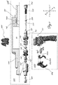
- an apparatus 100 for transdermal inoculation of medicaments and the like comprises :
- the first closing member 114 On its surface facing the inside of the chamber 111, the first closing member 114 has a seat 114c for receiving the end of a spring 115, the other end of which acts against a corresponding outer bearing surface 116a of a hollow piston 116, in turn arranged coaxially and axially slidably inside the rear chamber 111; the other surface of the piston also has, mounted thereon, an annular seal 116b, preferably of the lip type, for ensuring a relative sealing action for the air A supplied to the chamber 111 through the associated inlet 111d.
- a nozzle 140 which is provided with an associated outlet hole 140a and has, arranged inside it, a ball 141 which is pushed by a spring 141a towards a rear duct 142 connecting the nozzle to the front chamber 112 so that the duct is normally closed.
- a duct 143 which is radial in the example, for supplying the medicament M to be inoculated also leads into the front chamber 112.
- a firing plunger 150 is mounted thereon, said plunger being assembled at the rear inside a nipple 151 which is screwed onto the female thread 114c of the through-hole of the member 114 for closing the first chamber 111; in greater detail, the rear part of the plunger 150 has an annular projection 152 with an outer diameter substantially corresponding to the inner diameter of the nipple 151 so as to form an end-of-travel element making contact against the front wall 151a of the nipple provided with a through-hole 151b having an outer diameter corresponding to the outer diameter of the plunger 150; the annular projection 152 of the plunger 150 forms a support base for one end of a firing spring 153, the other end of which reacts against a member 154 for closing the rear of the nipple 151.
- said closing member consists of a ring 154 for adjusting the compression of the spring, which is screwed onto the second thread 151b of said nipple; said ring having a rear hole for allowing the end of the plunger 150 to protrude outwards.
- the plunger In a zone thereof axially corresponding to the axial position of the sleeve 117 carrying the balls 118, the plunger has an annular groove 155 designed to cooperate with the said balls 118 so as to cause coupling/release of the plunger with/from the piston 116.
- the rear free end of the plunger 150 has annular notches 150g, preferably marked with values of a numerical scale which correspond to different inoculation pressure values related to the different ages and type of animal and determined a priori on the basis of test measurements and which provide the user with a means for intuitive calibration of the thrusting force of the plunger.
- the apparatus according to the invention is easy and inexpensive to implement, manage, use and maintain, also by personnel who are not particularly skilled, and can be supplied with a fluid, such as compressed air, obtainable at a low cost by means of an ordinary compressor which can be found and installed in any location and at a negligble cost, without depending on any external service.
- a fluid such as compressed air
- the inoculating action is determined by the force imparted by the spring acting on the plunger, while subsequent rearming is performed by means of the supply fluid (compressed air), therefore eliminating the manual effort on the part of the operator with a consequent reduction in the fatigue and improved performance.
- the longitudinal dimensions of the apparatus may be kept small, thus resulting in better balance and therefore precision of the apparatus and a reduction in the fatigue of the operator, this fatigue being one of the main causes of imprecise or unsuccessful inoculation.
- use of the inoculation needle is eliminated also for the administration of large quantities of medicament and this results in the further advantages comprising:
- anatomical hand-grip 200 composed of:
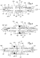
- the nipple 151 is coaxially inserted inside an axial extension 1111 of the body 111 and that the axial length of the rear part of the plunger 150 is reduced so as to occupy only a part of the inside of said nipple, so that the other, rear, part may contain the shank 1155a of a thruster 1155, the head 1155b of which external to the nipple 151 forms the bearing surface for the rear end of the spring 153.
- the presser 1155 is displaced by the end 1154a of a lever 1154 rotating about a transverse pin 1154b; conveniently the end 1154a of the lever 1154 acting on the presser 1155 is formed as a cam with a plurality of flat surfaces 1154c which are arranged at different inclinations so as to determine different thrusting forces of the presser 155 and therefore different compressions of the spring 153 acting during firing on the plunger 150 with consequent different forces for injection of medicament.
- Fig. 8 shows a further embodiment of the hand-grip 1200 which can be associated with the inoculation apparatus 1100 according to Fig. 7 ; this embodiment has a firing trigger 1213 and a safety locking element 1214 which, only when pressed, releases the supply of air A to the apparatus.
- the apparatus thus becomes a convenient, light and functional transdermal inoculation gun designed to ensure a high inoculation performance.
Landscapes
- Health & Medical Sciences (AREA)
- Vascular Medicine (AREA)
- Engineering & Computer Science (AREA)
- Anesthesiology (AREA)
- Biomedical Technology (AREA)
- Heart & Thoracic Surgery (AREA)
- Hematology (AREA)
- Life Sciences & Earth Sciences (AREA)
- Animal Behavior & Ethology (AREA)
- General Health & Medical Sciences (AREA)
- Public Health (AREA)
- Veterinary Medicine (AREA)
- Infusion, Injection, And Reservoir Apparatuses (AREA)
- Chemical Or Physical Treatment Of Fibers (AREA)
- Liquid Crystal (AREA)
Claims (8)
- Vorrichtung zur transdermalen Verabreichung von Medikamenten oder dergleichen, die sich in Längsrichtung (X-X) zwischen einem vorderen Ende zum Abgeben des Medikaments in Ausstoßrichtung und einem hinteren Ende gegenüber dem vorderen Ende erstreckt und Folgendes umfasst:• einen zylindrischen Mono-Körper (110) ausbildend- eine hintere Kammer (111) mit gegebenem Durchmesser mit einer vorderen Endfläche, die mit einem vorderen Einlass (111d) für Luft (A) versehen ist, die unter Druck zugeführt wird, um in einer Richtung entgegengesetzt zur Ausstoßrichtung zu wirken;- eine vordere Kammer (112) mit einem Durchmesser, der kleiner als der der hinteren Kammer (111) ist und mit einem zugeordneten Einlass (143) für das Medikament (M) versehen ist, wobei sich die Kammern koaxial in Längsrichtung (X-X) erstrecken und mittels einer Zwischenkammer (113) mit einem Durchmesser zwischen dem Durchmesser der anderen beiden Kammern (111; 112) miteinander verbunden sind;- ein erstes hinteres Schließelement (114) zum Schließen des zylindrischen Mono-Körpers (110), das die hintere Kammer (111) hinten begrenzt und eine koaxiale Durchgangsbohrung (114a) mit Innengewinde (114c) aufweist;- ein zweites vorderes Schließelement (123), das die hintere Kammer (111) vorne begrenzt und einen ringförmigen Kopf (123b) aufweist, der in Lagerkontakt mit der vorderen Endfläche der hinteren Kammer (111) treten kann und das ein durch dieses hindurchgehendes Durchgangsloch (123a) hat;• einen hohlen Scharfschaltkolben (116), der koaxial abgedichtet und axial verschiebbar in der hinteren Kammer (111) angeordnet ist, wobei der Kolben (116) umfasst:- eine äußere Lagerfläche (116a),- eine hintere Endfläche (116d),- ein Loch (116c), das in der hinteren Endfläche (116d) ausgebildet ist,- eine Basis mit einem Sitz (116f);• eine erste Feder (115), die zwischen der äußeren Lagerfläche (116a) des Kolbens (116) und dem ersten hinteren Schließelement (114) angeordnet ist;• eine hohle Hülse (117), die koaxial in den Kolben (116) eingesetzt ist und die umfasst:- einen axial hinteren Teil mit einem Außendurchmesser, der dem Innendurchmesser des Lochs (116c) entspricht, das in der hinteren Endfläche (116d) des Kolbens (116) ausgebildet ist;- ein vorderes Teil mit einem Außendurchmesser, der dem Innendurchmesser des Kolbens (116) entspricht;- die Hülse (117) hat innen einen ringförmigen Vorsprung (117a) zum Zusammenwirken mit einer Vielzahl von Kugeln (118) und einen ringförmigen Sitz (117b) zur teilweisen Aufnahme der Vielzahl von Kugeln (118), die axial hintereinander von dem vorderen Ende bis zu dem hinteren Ende der Vorrichtung angeordnet sind;• ein im wesentlichen T-förmiges Schubstück (119) mit:- einem Schaft (119a) mit einem Außendurchmesser, der dem Innendurchmesser der hohlen Hülse (117) entspricht, in die es teilweise in axialer Richtung eindringt, und- einem Kopf (119b) mit einem Außendurchmesser, um einen Lagerkontakt innerhalb des entsprechenden Sitzes (116f) der Basis des Kolbens (116) herzustellen;• eine Schubfeder (120), die zwischen dem Kopf (119b) des Schubstücks (119) und dem vorderen Teil der Hülse (117) und konzentrisch zu der auf den Scharfschaltkolben wirkenden Feder (115) angeordnet ist;• eine Düse (140), die mit einem zugehörigen Auslassloch (140a) versehen ist und in der eine Kugel (141) angeordnet ist, die von einer Feder (141a) in Richtung eines hinteren Kanals (142) gedrückt wird, der die Düse mit der vordere Kammer (112) verbindet, so dass der Kanal normalerweise geschlossen ist;• einen Ausstoßstößel (150), der koaxial in dem zylindrischen Körper (110) enthalten ist und mit einem hinteren Teil versehen ist, der einen ringförmigen Vorsprung (152) mit gegebenem Außendurchmesser aufweist;• einen Nippel (151), der auf das Innengewinde (114c) des Durchgangslochs des Schließelements (114) aufgeschraubt ist, wobei der Nippel- einen Innendurchmesser aufweist, der im Wesentlichen dem Außendurchmesser des ringförmigen Vorsprungs (152) des rückseitigen Teils des Stößels (150) entspricht;- eine Vorderwand (151a) mit einem Durchgangsloch (151b) mit einem Innendurchmesser, der dem Außendurchmesser des Stößels (150) entspricht;- ein hinteres Schließelement (154; 1154);• eine Ausstoßfeder (153), die zwischen dem hinteren Schließelement (154; 1154) des Nippels und dem ringförmigen Vorsprung (152) des Ausstoßstößels (150) angeordnet ist und mit einer Schubkraft darauf wirkt;wobei der Ausstoßstößel (150) mit einer ringförmigen Aussparung (155) versehen ist, die geeignet ist, mit der Vielzahl von Kugeln (118) zusammenzuwirken, um das Koppeln/Freigeben des Stößels (150) mit/von dem Kolben (116) zu bewirken, so dass in einer Ruheposition der Vorrichtung der Stößel (150) mit dem bewegungsbegrenzenden ringförmigen Vorsprung (152) gegen die Vorderwand (151a) des Nippels (151) nach vorne gedrückt wird, wobei die ringförmige Aussparung (155) des Stößels (150) axial ausgerichtet mit der Vielzahl von Kugeln (118) angeordnet ist, die durch den ringförmigen Vorsprung (117a) der Hülse (117) radial in Richtung der Längsachse (X-X) gedrückt gehalten werden, so dass der Stößel (150) starr mit dem Kolben (116) gekoppelt ist;
und wobei durch die Zufuhr von Luft (A) in die hintere Kammer (111) über den Einlass mit einem Druck, der die Schubkraft der ersten Feder (115) und der Ausstoßfeder (153) überwindet, der Kolben (116) und der Stößel (150) gleichzeitig aus dem Ruhezustand in Richtung der Rückseite der hinteren Kammer (111) verschoben werden, bis die Hülse (117) in axialen Lagerkontakt mit dem Nippel (151) des hinteren Verschlusselements (114) kommt, wobei durch das Zurückziehen des Stößels (150) ein Vakuum in der vorderen Kammer (112) erzeugt wird, das das Ansaugen einer vordefinierten Menge an Medikament (M) bewirkt;
und wobei der Stößel (150) bei Fortsetzung der Luftzufuhr (A) aus dem Eingriff mit dem Kolben (116) befreit wird und somit durch die Schubkraft der zuvor zusammengedrückten Ausstoßfeder (153) heftig nach vorne gedrückt wird, wodurch das Medikament (M) durch die Düse (140) abgegeben wird. - Vorrichtung nach Anspruch 1,
dadurch gekennzeichnet,
dass das das hintere Ende des Nippels (151) verschließende Element durch eine Ringmutter (154) gebildet ist, die auf ein hinteres Gewinde (151b) des Nippels aufgeschraubt ist. - Vorrichtung nach Anspruch 2,
dadurch gekennzeichnet,
dass die Ringmutter ein hinteres Loch aufweist, damit das hintere Ende des Bolzens (150) nach außen vorstehen kann. - Vorrichtung nach Anspruch 3,
dadurch gekennzeichnet,
dass das hintere Ende des Stößels (150) ringförmige Kerben (150g) aufweist, die mit Werten einer numerischen Skala gekennzeichnet sind, die verschiedenen Verabreichungsdruckwerten entsprechen. - Vorrichtung nach Anspruch 1,
dadurch gekennzeichnet,
dass der Körper (111) eine axiale Verlängerung (1111) aufweist, in die der Nippel (151) koaxial eingesetzt ist und dass die axiale Länge des hinteren Teils des Stößels (150) ausreichend klein ist, um nur einen axialen Teil der Innenseite des Nippels aufzunehmen. - Vorrichtung nach Anspruch 5,
dadurch gekennzeichnet,
dass sie einen Drücker (1155) umfasst, der einen Schaft (1155a) aufweist, der im inneren hinteren Teil des Nippels (151) enthalten ist und dessen Kopf (1155b) außerhalb des Nippels (151) liegt und die Auflagefläche für das hintere Ende der Feder (153) bildet. - Vorrichtung nach Anspruch 6,
dadurch gekennzeichnet,
dass sie Mittel zum Einstellen der Kompression der Ausstoßfeder (153) umfasst, die einen Hebel (1154) umfassen, der um einen Querbolzen (1154b) drehbar ist und dessen auf den Drücker (1155) einwirkendes Ende (1154a) die Form eines Nockens mit mehreren ebenen Flächen (1154c) aufweist, die in unterschiedlichen Neigungen angeordnet sind. - Vorrichtung nach einem der vorhergehenden Ansprüche,
dadurch gekennzeichnet,
dass sie einen Handgriff (200; 1200) mit zugeordnetem Ventil (212) zum Zuführen der Druckluft (A), einen Betätigungshebel (213; 1213) und ein Sicherheitselement umfasst (214; 1214) zum Verhindern eines versehentlichen Ausstoßes.
Applications Claiming Priority (1)
| Application Number | Priority Date | Filing Date | Title |
|---|---|---|---|
| IT002067A ITMI20132067A1 (it) | 2013-12-11 | 2013-12-11 | Apparecchiatura per l'inoculazione transdermica di medicamenti |
Publications (2)
| Publication Number | Publication Date |
|---|---|
| EP2896420A1 EP2896420A1 (de) | 2015-07-22 |
| EP2896420B1 true EP2896420B1 (de) | 2020-05-27 |
Family
ID=49958576
Family Applications (1)
| Application Number | Title | Priority Date | Filing Date |
|---|---|---|---|
| EP14196904.8A Active EP2896420B1 (de) | 2013-12-11 | 2014-12-09 | Vorrichtung zur nadellosen transdermalen Verabreichung von Arzneimitteln |
Country Status (3)
| Country | Link |
|---|---|
| EP (1) | EP2896420B1 (de) |
| ES (1) | ES2808773T3 (de) |
| IT (1) | ITMI20132067A1 (de) |
Family Cites Families (8)
| Publication number | Priority date | Publication date | Assignee | Title |
|---|---|---|---|---|
| GB766431A (en) * | 1953-02-11 | 1957-01-23 | Nat Res Dev | Improvements relating to hypodermic injection apparatus |
| US3057349A (en) * | 1959-12-14 | 1962-10-09 | Ismach Aaron | Multi-dose jet injection device |
| US4103684A (en) * | 1976-12-30 | 1978-08-01 | Aaron Ismach | Hydraulically powered hypodermic injector with adapters for reducing and increasing fluid injection force |
| DE3115376A1 (de) * | 1981-04-16 | 1982-12-16 | Hoechst Ag, 6000 Frankfurt | Nadelloses injektionsgeraet |
| FR2629706B1 (fr) * | 1988-04-11 | 1992-05-22 | Accaries Claude | Appareil d'injection de liquide, notamment a usage de soins dentaires |
| US6939319B1 (en) * | 2002-11-20 | 2005-09-06 | Conrad Anstead | Process and device for single use, needle-free intradermal, subcutaneous, or intramuscular injections |
| WO2012048268A2 (en) | 2010-10-07 | 2012-04-12 | Massachusetts Instiute Of Technology | Delivery of a solid body and/or a fluid using a linear lorentz-force actuated needle-free jet injection system |
| JP2014508565A (ja) | 2011-01-10 | 2014-04-10 | ゾゲニクス インコーポレーティッド | 改善された無針注射器 |
-
2013
- 2013-12-11 IT IT002067A patent/ITMI20132067A1/it unknown
-
2014
- 2014-12-09 EP EP14196904.8A patent/EP2896420B1/de active Active
- 2014-12-09 ES ES14196904T patent/ES2808773T3/es active Active
Non-Patent Citations (1)
| Title |
|---|
| None * |
Also Published As
| Publication number | Publication date |
|---|---|
| ITMI20132067A1 (it) | 2015-06-12 |
| EP2896420A1 (de) | 2015-07-22 |
| ES2808773T3 (es) | 2021-03-01 |
Similar Documents
| Publication | Publication Date | Title |
|---|---|---|
| US20220226582A1 (en) | Autoinjector | |
| US5549560A (en) | Apparatus and method for injecting a pharmaceutical preparation in solid form | |
| EP1474192B1 (de) | Nadelloser injektor | |
| KR20120116428A (ko) | 바늘없는 주사장치 | |
| AU2011329575B2 (en) | Medicament delivery device | |
| US20040158195A1 (en) | Needle-free mass injection device | |
| US10434257B2 (en) | Powered injection device for delivering multiple liquid formulations, including vaccines | |
| CN113082388B (zh) | 气动无针注射器 | |
| CN107397606B (zh) | 一种兽医用注射器 | |
| US20040129803A1 (en) | Triggering means for a pressure jet injector | |
| JP2022528596A (ja) | 液体を投与するための投与装置 | |
| EP2896420B1 (de) | Vorrichtung zur nadellosen transdermalen Verabreichung von Arzneimitteln | |
| CN218852891U (zh) | 一种无针注射器 | |
| CN102512733A (zh) | 一次性使用的无针注射器 | |
| KR200488129Y1 (ko) | 백신 표식기 | |
| CN204932479U (zh) | 无针注射器 | |
| AU2002332125B2 (en) | Jet injector with hand piece | |
| EP1225842B1 (de) | Gerät zur medikamenteninjektion bei tieren | |
| EP3344313B1 (de) | Injektor | |
| WO2022129402A1 (en) | Medication delivery device |
Legal Events
| Date | Code | Title | Description |
|---|---|---|---|
| PUAI | Public reference made under article 153(3) epc to a published international application that has entered the european phase |
Free format text: ORIGINAL CODE: 0009012 |
|
| 17P | Request for examination filed |
Effective date: 20141209 |
|
| AK | Designated contracting states |
Kind code of ref document: A1 Designated state(s): AL AT BE BG CH CY CZ DE DK EE ES FI FR GB GR HR HU IE IS IT LI LT LU LV MC MK MT NL NO PL PT RO RS SE SI SK SM TR |
|
| AX | Request for extension of the european patent |
Extension state: BA ME |
|
| 17P | Request for examination filed |
Effective date: 20160120 |
|
| RBV | Designated contracting states (corrected) |
Designated state(s): AL AT BE BG CH CY CZ DE DK EE ES FI FR GB GR HR HU IE IS IT LI LT LU LV MC MK MT NL NO PL PT RO RS SE SI SK SM TR |
|
| STAA | Information on the status of an ep patent application or granted ep patent |
Free format text: STATUS: EXAMINATION IS IN PROGRESS |
|
| 17Q | First examination report despatched |
Effective date: 20180810 |
|
| GRAP | Despatch of communication of intention to grant a patent |
Free format text: ORIGINAL CODE: EPIDOSNIGR1 |
|
| STAA | Information on the status of an ep patent application or granted ep patent |
Free format text: STATUS: GRANT OF PATENT IS INTENDED |
|
| INTG | Intention to grant announced |
Effective date: 20191108 |
|
| INTG | Intention to grant announced |
Effective date: 20191113 |
|
| GRAS | Grant fee paid |
Free format text: ORIGINAL CODE: EPIDOSNIGR3 |
|
| GRAJ | Information related to disapproval of communication of intention to grant by the applicant or resumption of examination proceedings by the epo deleted |
Free format text: ORIGINAL CODE: EPIDOSDIGR1 |
|
| GRAL | Information related to payment of fee for publishing/printing deleted |
Free format text: ORIGINAL CODE: EPIDOSDIGR3 |
|
| STAA | Information on the status of an ep patent application or granted ep patent |
Free format text: STATUS: EXAMINATION IS IN PROGRESS |
|
| GRAR | Information related to intention to grant a patent recorded |
Free format text: ORIGINAL CODE: EPIDOSNIGR71 |
|
| STAA | Information on the status of an ep patent application or granted ep patent |
Free format text: STATUS: GRANT OF PATENT IS INTENDED |
|
| GRAJ | Information related to disapproval of communication of intention to grant by the applicant or resumption of examination proceedings by the epo deleted |
Free format text: ORIGINAL CODE: EPIDOSDIGR1 |
|
| STAA | Information on the status of an ep patent application or granted ep patent |
Free format text: STATUS: EXAMINATION IS IN PROGRESS |
|
| INTC | Intention to grant announced (deleted) | ||
| GRAR | Information related to intention to grant a patent recorded |
Free format text: ORIGINAL CODE: EPIDOSNIGR71 |
|
| STAA | Information on the status of an ep patent application or granted ep patent |
Free format text: STATUS: GRANT OF PATENT IS INTENDED |
|
| GRAA | (expected) grant |
Free format text: ORIGINAL CODE: 0009210 |
|
| STAA | Information on the status of an ep patent application or granted ep patent |
Free format text: STATUS: THE PATENT HAS BEEN GRANTED |
|
| AK | Designated contracting states |
Kind code of ref document: B1 Designated state(s): AL AT BE BG CH CY CZ DE DK EE ES FI FR GB GR HR HU IE IS IT LI LT LU LV MC MK MT NL NO PL PT RO RS SE SI SK SM TR |
|
| INTG | Intention to grant announced |
Effective date: 20200420 |
|
| REG | Reference to a national code |
Ref country code: GB Ref legal event code: FG4D |
|
| REG | Reference to a national code |
Ref country code: CH Ref legal event code: EP |
|
| REG | Reference to a national code |
Ref country code: AT Ref legal event code: REF Ref document number: 1273880 Country of ref document: AT Kind code of ref document: T Effective date: 20200615 |
|
| REG | Reference to a national code |
Ref country code: DE Ref legal event code: R096 Ref document number: 602014065849 Country of ref document: DE |
|
| REG | Reference to a national code |
Ref country code: LT Ref legal event code: MG4D |
|
| PG25 | Lapsed in a contracting state [announced via postgrant information from national office to epo] |
Ref country code: IS Free format text: LAPSE BECAUSE OF FAILURE TO SUBMIT A TRANSLATION OF THE DESCRIPTION OR TO PAY THE FEE WITHIN THE PRESCRIBED TIME-LIMIT Effective date: 20200927 Ref country code: NO Free format text: LAPSE BECAUSE OF FAILURE TO SUBMIT A TRANSLATION OF THE DESCRIPTION OR TO PAY THE FEE WITHIN THE PRESCRIBED TIME-LIMIT Effective date: 20200827 Ref country code: FI Free format text: LAPSE BECAUSE OF FAILURE TO SUBMIT A TRANSLATION OF THE DESCRIPTION OR TO PAY THE FEE WITHIN THE PRESCRIBED TIME-LIMIT Effective date: 20200527 Ref country code: GR Free format text: LAPSE BECAUSE OF FAILURE TO SUBMIT A TRANSLATION OF THE DESCRIPTION OR TO PAY THE FEE WITHIN THE PRESCRIBED TIME-LIMIT Effective date: 20200828 Ref country code: LT Free format text: LAPSE BECAUSE OF FAILURE TO SUBMIT A TRANSLATION OF THE DESCRIPTION OR TO PAY THE FEE WITHIN THE PRESCRIBED TIME-LIMIT Effective date: 20200527 Ref country code: SE Free format text: LAPSE BECAUSE OF FAILURE TO SUBMIT A TRANSLATION OF THE DESCRIPTION OR TO PAY THE FEE WITHIN THE PRESCRIBED TIME-LIMIT Effective date: 20200527 Ref country code: PT Free format text: LAPSE BECAUSE OF FAILURE TO SUBMIT A TRANSLATION OF THE DESCRIPTION OR TO PAY THE FEE WITHIN THE PRESCRIBED TIME-LIMIT Effective date: 20200928 |
|
| REG | Reference to a national code |
Ref country code: NL Ref legal event code: MP Effective date: 20200527 |
|
| PG25 | Lapsed in a contracting state [announced via postgrant information from national office to epo] |
Ref country code: RS Free format text: LAPSE BECAUSE OF FAILURE TO SUBMIT A TRANSLATION OF THE DESCRIPTION OR TO PAY THE FEE WITHIN THE PRESCRIBED TIME-LIMIT Effective date: 20200527 Ref country code: BG Free format text: LAPSE BECAUSE OF FAILURE TO SUBMIT A TRANSLATION OF THE DESCRIPTION OR TO PAY THE FEE WITHIN THE PRESCRIBED TIME-LIMIT Effective date: 20200827 Ref country code: HR Free format text: LAPSE BECAUSE OF FAILURE TO SUBMIT A TRANSLATION OF THE DESCRIPTION OR TO PAY THE FEE WITHIN THE PRESCRIBED TIME-LIMIT Effective date: 20200527 Ref country code: LV Free format text: LAPSE BECAUSE OF FAILURE TO SUBMIT A TRANSLATION OF THE DESCRIPTION OR TO PAY THE FEE WITHIN THE PRESCRIBED TIME-LIMIT Effective date: 20200527 |
|
| REG | Reference to a national code |
Ref country code: AT Ref legal event code: MK05 Ref document number: 1273880 Country of ref document: AT Kind code of ref document: T Effective date: 20200527 |
|
| PG25 | Lapsed in a contracting state [announced via postgrant information from national office to epo] |
Ref country code: AL Free format text: LAPSE BECAUSE OF FAILURE TO SUBMIT A TRANSLATION OF THE DESCRIPTION OR TO PAY THE FEE WITHIN THE PRESCRIBED TIME-LIMIT Effective date: 20200527 Ref country code: NL Free format text: LAPSE BECAUSE OF FAILURE TO SUBMIT A TRANSLATION OF THE DESCRIPTION OR TO PAY THE FEE WITHIN THE PRESCRIBED TIME-LIMIT Effective date: 20200527 |
|
| PG25 | Lapsed in a contracting state [announced via postgrant information from national office to epo] |
Ref country code: EE Free format text: LAPSE BECAUSE OF FAILURE TO SUBMIT A TRANSLATION OF THE DESCRIPTION OR TO PAY THE FEE WITHIN THE PRESCRIBED TIME-LIMIT Effective date: 20200527 Ref country code: AT Free format text: LAPSE BECAUSE OF FAILURE TO SUBMIT A TRANSLATION OF THE DESCRIPTION OR TO PAY THE FEE WITHIN THE PRESCRIBED TIME-LIMIT Effective date: 20200527 Ref country code: SM Free format text: LAPSE BECAUSE OF FAILURE TO SUBMIT A TRANSLATION OF THE DESCRIPTION OR TO PAY THE FEE WITHIN THE PRESCRIBED TIME-LIMIT Effective date: 20200527 Ref country code: DK Free format text: LAPSE BECAUSE OF FAILURE TO SUBMIT A TRANSLATION OF THE DESCRIPTION OR TO PAY THE FEE WITHIN THE PRESCRIBED TIME-LIMIT Effective date: 20200527 Ref country code: CZ Free format text: LAPSE BECAUSE OF FAILURE TO SUBMIT A TRANSLATION OF THE DESCRIPTION OR TO PAY THE FEE WITHIN THE PRESCRIBED TIME-LIMIT Effective date: 20200527 Ref country code: RO Free format text: LAPSE BECAUSE OF FAILURE TO SUBMIT A TRANSLATION OF THE DESCRIPTION OR TO PAY THE FEE WITHIN THE PRESCRIBED TIME-LIMIT Effective date: 20200527 |
|
| PG25 | Lapsed in a contracting state [announced via postgrant information from national office to epo] |
Ref country code: SK Free format text: LAPSE BECAUSE OF FAILURE TO SUBMIT A TRANSLATION OF THE DESCRIPTION OR TO PAY THE FEE WITHIN THE PRESCRIBED TIME-LIMIT Effective date: 20200527 Ref country code: PL Free format text: LAPSE BECAUSE OF FAILURE TO SUBMIT A TRANSLATION OF THE DESCRIPTION OR TO PAY THE FEE WITHIN THE PRESCRIBED TIME-LIMIT Effective date: 20200527 |
|
| REG | Reference to a national code |
Ref country code: ES Ref legal event code: FG2A Ref document number: 2808773 Country of ref document: ES Kind code of ref document: T3 Effective date: 20210301 |
|
| REG | Reference to a national code |
Ref country code: DE Ref legal event code: R097 Ref document number: 602014065849 Country of ref document: DE |
|
| PLBE | No opposition filed within time limit |
Free format text: ORIGINAL CODE: 0009261 |
|
| STAA | Information on the status of an ep patent application or granted ep patent |
Free format text: STATUS: NO OPPOSITION FILED WITHIN TIME LIMIT |
|
| 26N | No opposition filed |
Effective date: 20210302 |
|
| PG25 | Lapsed in a contracting state [announced via postgrant information from national office to epo] |
Ref country code: SI Free format text: LAPSE BECAUSE OF FAILURE TO SUBMIT A TRANSLATION OF THE DESCRIPTION OR TO PAY THE FEE WITHIN THE PRESCRIBED TIME-LIMIT Effective date: 20200527 |
|
| REG | Reference to a national code |
Ref country code: CH Ref legal event code: PL |
|
| GBPC | Gb: european patent ceased through non-payment of renewal fee |
Effective date: 20201209 |
|
| PG25 | Lapsed in a contracting state [announced via postgrant information from national office to epo] |
Ref country code: MC Free format text: LAPSE BECAUSE OF FAILURE TO SUBMIT A TRANSLATION OF THE DESCRIPTION OR TO PAY THE FEE WITHIN THE PRESCRIBED TIME-LIMIT Effective date: 20200527 |
|
| REG | Reference to a national code |
Ref country code: BE Ref legal event code: MM Effective date: 20201231 |
|
| PG25 | Lapsed in a contracting state [announced via postgrant information from national office to epo] |
Ref country code: IE Free format text: LAPSE BECAUSE OF NON-PAYMENT OF DUE FEES Effective date: 20201209 Ref country code: LU Free format text: LAPSE BECAUSE OF NON-PAYMENT OF DUE FEES Effective date: 20201209 |
|
| PG25 | Lapsed in a contracting state [announced via postgrant information from national office to epo] |
Ref country code: GB Free format text: LAPSE BECAUSE OF NON-PAYMENT OF DUE FEES Effective date: 20201209 Ref country code: CH Free format text: LAPSE BECAUSE OF NON-PAYMENT OF DUE FEES Effective date: 20201231 Ref country code: LI Free format text: LAPSE BECAUSE OF NON-PAYMENT OF DUE FEES Effective date: 20201231 |
|
| PG25 | Lapsed in a contracting state [announced via postgrant information from national office to epo] |
Ref country code: TR Free format text: LAPSE BECAUSE OF FAILURE TO SUBMIT A TRANSLATION OF THE DESCRIPTION OR TO PAY THE FEE WITHIN THE PRESCRIBED TIME-LIMIT Effective date: 20200527 Ref country code: MT Free format text: LAPSE BECAUSE OF FAILURE TO SUBMIT A TRANSLATION OF THE DESCRIPTION OR TO PAY THE FEE WITHIN THE PRESCRIBED TIME-LIMIT Effective date: 20200527 Ref country code: CY Free format text: LAPSE BECAUSE OF FAILURE TO SUBMIT A TRANSLATION OF THE DESCRIPTION OR TO PAY THE FEE WITHIN THE PRESCRIBED TIME-LIMIT Effective date: 20200527 |
|
| PG25 | Lapsed in a contracting state [announced via postgrant information from national office to epo] |
Ref country code: MK Free format text: LAPSE BECAUSE OF FAILURE TO SUBMIT A TRANSLATION OF THE DESCRIPTION OR TO PAY THE FEE WITHIN THE PRESCRIBED TIME-LIMIT Effective date: 20200527 |
|
| PG25 | Lapsed in a contracting state [announced via postgrant information from national office to epo] |
Ref country code: BE Free format text: LAPSE BECAUSE OF NON-PAYMENT OF DUE FEES Effective date: 20201231 |
|
| PGFP | Annual fee paid to national office [announced via postgrant information from national office to epo] |
Ref country code: FR Payment date: 20221214 Year of fee payment: 9 Ref country code: DE Payment date: 20221216 Year of fee payment: 9 |
|
| PGFP | Annual fee paid to national office [announced via postgrant information from national office to epo] |
Ref country code: ES Payment date: 20230102 Year of fee payment: 9 |
|
| P01 | Opt-out of the competence of the unified patent court (upc) registered |
Effective date: 20230313 |
|
| REG | Reference to a national code |
Ref country code: DE Ref legal event code: R119 Ref document number: 602014065849 Country of ref document: DE |
|
| PG25 | Lapsed in a contracting state [announced via postgrant information from national office to epo] |
Ref country code: DE Free format text: LAPSE BECAUSE OF NON-PAYMENT OF DUE FEES Effective date: 20240702 |
|
| PG25 | Lapsed in a contracting state [announced via postgrant information from national office to epo] |
Ref country code: FR Free format text: LAPSE BECAUSE OF NON-PAYMENT OF DUE FEES Effective date: 20231231 |
|
| PG25 | Lapsed in a contracting state [announced via postgrant information from national office to epo] |
Ref country code: FR Free format text: LAPSE BECAUSE OF NON-PAYMENT OF DUE FEES Effective date: 20231231 Ref country code: DE Free format text: LAPSE BECAUSE OF NON-PAYMENT OF DUE FEES Effective date: 20240702 |
|
| PGFP | Annual fee paid to national office [announced via postgrant information from national office to epo] |
Ref country code: IT Payment date: 20241218 Year of fee payment: 11 |
|
| REG | Reference to a national code |
Ref country code: ES Ref legal event code: FD2A Effective date: 20250129 |
|
| PG25 | Lapsed in a contracting state [announced via postgrant information from national office to epo] |
Ref country code: ES Free format text: LAPSE BECAUSE OF NON-PAYMENT OF DUE FEES Effective date: 20231210 |
|
| PG25 | Lapsed in a contracting state [announced via postgrant information from national office to epo] |
Ref country code: IS Free format text: LAPSE BECAUSE OF NON-PAYMENT OF DUE FEES Effective date: 20200927 |