EP2896420B1 - Apparatus for needleless transdermal inoculation of medicaments - Google Patents
Apparatus for needleless transdermal inoculation of medicaments Download PDFInfo
- Publication number
- EP2896420B1 EP2896420B1 EP14196904.8A EP14196904A EP2896420B1 EP 2896420 B1 EP2896420 B1 EP 2896420B1 EP 14196904 A EP14196904 A EP 14196904A EP 2896420 B1 EP2896420 B1 EP 2896420B1
- Authority
- EP
- European Patent Office
- Prior art keywords
- plunger
- piston
- nipple
- chamber
- firing
- Prior art date
- Legal status (The legal status is an assumption and is not a legal conclusion. Google has not performed a legal analysis and makes no representation as to the accuracy of the status listed.)
- Active
Links
- 239000003814 drug Substances 0.000 title claims description 27
- 238000011081 inoculation Methods 0.000 title claims description 22
- 238000010304 firing Methods 0.000 claims description 22
- 210000002445 nipple Anatomy 0.000 claims description 21
- 230000006835 compression Effects 0.000 claims description 3
- 238000007906 compression Methods 0.000 claims description 3
- 238000007599 discharging Methods 0.000 claims description 3
- 230000004323 axial length Effects 0.000 claims description 2
- 230000008878 coupling Effects 0.000 claims description 2
- 238000010168 coupling process Methods 0.000 claims description 2
- 238000005859 coupling reaction Methods 0.000 claims description 2
- 230000002452 interceptive effect Effects 0.000 claims 1
- 241001465754 Metazoa Species 0.000 description 11
- 239000012530 fluid Substances 0.000 description 7
- 238000002347 injection Methods 0.000 description 7
- 239000007924 injection Substances 0.000 description 7
- 229960005486 vaccine Drugs 0.000 description 4
- 230000008030 elimination Effects 0.000 description 3
- 238000003379 elimination reaction Methods 0.000 description 3
- 230000005540 biological transmission Effects 0.000 description 2
- 239000007789 gas Substances 0.000 description 2
- 244000144972 livestock Species 0.000 description 2
- 238000003860 storage Methods 0.000 description 2
- 208000035143 Bacterial infection Diseases 0.000 description 1
- 208000032843 Hemorrhage Diseases 0.000 description 1
- 241000282849 Ruminantia Species 0.000 description 1
- 241000282887 Suidae Species 0.000 description 1
- 208000027418 Wounds and injury Diseases 0.000 description 1
- 206010000269 abscess Diseases 0.000 description 1
- 239000003242 anti bacterial agent Substances 0.000 description 1
- 229940088710 antibiotic agent Drugs 0.000 description 1
- 208000022362 bacterial infectious disease Diseases 0.000 description 1
- 238000006243 chemical reaction Methods 0.000 description 1
- 238000007796 conventional method Methods 0.000 description 1
- 230000006378 damage Effects 0.000 description 1
- 230000001419 dependent effect Effects 0.000 description 1
- 229940079593 drug Drugs 0.000 description 1
- 230000000642 iatrogenic effect Effects 0.000 description 1
- 239000011261 inert gas Substances 0.000 description 1
- 208000015181 infectious disease Diseases 0.000 description 1
- 230000036512 infertility Effects 0.000 description 1
- 208000014674 injury Diseases 0.000 description 1
- 238000003780 insertion Methods 0.000 description 1
- 230000037431 insertion Effects 0.000 description 1
- 238000007918 intramuscular administration Methods 0.000 description 1
- 238000004519 manufacturing process Methods 0.000 description 1
- 238000005259 measurement Methods 0.000 description 1
- 239000002184 metal Substances 0.000 description 1
- 210000003205 muscle Anatomy 0.000 description 1
- 230000003387 muscular Effects 0.000 description 1
- 238000009304 pastoral farming Methods 0.000 description 1
- 230000035515 penetration Effects 0.000 description 1
- 244000144977 poultry Species 0.000 description 1
- 238000003825 pressing Methods 0.000 description 1
- 230000000384 rearing effect Effects 0.000 description 1
- 238000007789 sealing Methods 0.000 description 1
- 239000000243 solution Substances 0.000 description 1
- 238000012360 testing method Methods 0.000 description 1
- 210000003813 thumb Anatomy 0.000 description 1
- 230000000472 traumatic effect Effects 0.000 description 1
Images


Classifications
-
- A—HUMAN NECESSITIES
- A61—MEDICAL OR VETERINARY SCIENCE; HYGIENE
- A61M—DEVICES FOR INTRODUCING MEDIA INTO, OR ONTO, THE BODY; DEVICES FOR TRANSDUCING BODY MEDIA OR FOR TAKING MEDIA FROM THE BODY; DEVICES FOR PRODUCING OR ENDING SLEEP OR STUPOR
- A61M5/00—Devices for bringing media into the body in a subcutaneous, intra-vascular or intramuscular way; Accessories therefor, e.g. filling or cleaning devices, arm-rests
- A61M5/178—Syringes
- A61M5/30—Syringes for injection by jet action, without needle, e.g. for use with replaceable ampoules or carpules
-
- A—HUMAN NECESSITIES
- A61—MEDICAL OR VETERINARY SCIENCE; HYGIENE
- A61M—DEVICES FOR INTRODUCING MEDIA INTO, OR ONTO, THE BODY; DEVICES FOR TRANSDUCING BODY MEDIA OR FOR TAKING MEDIA FROM THE BODY; DEVICES FOR PRODUCING OR ENDING SLEEP OR STUPOR
- A61M5/00—Devices for bringing media into the body in a subcutaneous, intra-vascular or intramuscular way; Accessories therefor, e.g. filling or cleaning devices, arm-rests
- A61M5/178—Syringes
- A61M5/20—Automatic syringes, e.g. with automatically actuated piston rod, with automatic needle injection, filling automatically
- A61M2005/2006—Having specific accessories
- A61M2005/202—Having specific accessories cocking means, e.g. to bias the main drive spring of an injector
-
- A—HUMAN NECESSITIES
- A61—MEDICAL OR VETERINARY SCIENCE; HYGIENE
- A61M—DEVICES FOR INTRODUCING MEDIA INTO, OR ONTO, THE BODY; DEVICES FOR TRANSDUCING BODY MEDIA OR FOR TAKING MEDIA FROM THE BODY; DEVICES FOR PRODUCING OR ENDING SLEEP OR STUPOR
- A61M5/00—Devices for bringing media into the body in a subcutaneous, intra-vascular or intramuscular way; Accessories therefor, e.g. filling or cleaning devices, arm-rests
- A61M5/178—Syringes
- A61M5/20—Automatic syringes, e.g. with automatically actuated piston rod, with automatic needle injection, filling automatically
- A61M5/204—Automatic syringes, e.g. with automatically actuated piston rod, with automatic needle injection, filling automatically connected to external reservoirs for multiple refilling
-
- A—HUMAN NECESSITIES
- A61—MEDICAL OR VETERINARY SCIENCE; HYGIENE
- A61M—DEVICES FOR INTRODUCING MEDIA INTO, OR ONTO, THE BODY; DEVICES FOR TRANSDUCING BODY MEDIA OR FOR TAKING MEDIA FROM THE BODY; DEVICES FOR PRODUCING OR ENDING SLEEP OR STUPOR
- A61M5/00—Devices for bringing media into the body in a subcutaneous, intra-vascular or intramuscular way; Accessories therefor, e.g. filling or cleaning devices, arm-rests
- A61M5/48—Devices for bringing media into the body in a subcutaneous, intra-vascular or intramuscular way; Accessories therefor, e.g. filling or cleaning devices, arm-rests having means for varying, regulating, indicating or limiting injection pressure
- A61M5/484—Regulating injection pressure
Definitions
- the present invention relates to an apparatus for transdermal inoculation of medicaments such as vaccines and the like into the muscle of an animal. It is known in the sector of intensive livestock farming of animals such as poultry, pigs and ruminants that there exists the need to administer to said animals medicaments in general, vaccines, antibiotics and the like.
- CA 2 822 908 A1 and WO2012/048268 A2 disclose administration devices which are designed to introduce the medicament without the use of needles, but by using the discharge thrust of the fluid from a chamber which is placed under pressure by means of a quantity of gas contained inside a pressurised cartridge or by the action of a plunger.
- US 3 057 349 describes an inoculation gun in which firing is performed by a spring prestressed by a hydraulic fluid under pressure supplied to a metering chamber, the fluid keeping the spring compressed until the chamber is rapidly emptied of the fluid, allowing firing.
- a further example of an injection apparatus according to the prior art is described in FR 2 629 706 .
- the apparatus is formed by a cylindrical container consisting of two parts which can be separated so as to allow insertion of the phial containing the medicament to be injected.
- This embodiment gives rise to numerous complications resulting from the need to form an internal space for housing the phial, with the result that the springs for rearming the device must be arranged in opposite positions with respect to the phial itself.
- operation of the apparatus is based, on the one hand, on a firing action caused by the feeding of compressed air supplied to the front end of the apparatus and acting in the same direction as that of injection of the medicament and, on the other hand, on a mechanical arming action performed by the springs arranged along the containing cylinder.
- Both the known apparatus have a highly complex structure formed by a large number of parts, as well as large dimensions and complex and costly auxiliary operating components.
- the technical problem which is posed, therefore, is that of providing an apparatus which provides a solution to the problems of the prior art mentioned above and which in particular is designed to allow the transdermal inoculation, to the correct depth, of medicaments or the like, including also large quantities of vaccine also for large animals.
- this apparatus should have small dimensions and be easy and inexpensive to produce and assemble by means of standard apparatus which can be easily used and maintained.
- a set of three axes having, respectively, a longitudinal axial direction X-X, corresponding to the direction of axial extension of the apparatus, transverse/radial direction Y-Y orthogonal to the preceding direction, and vertical direction Z-Z, orthogonal to the plane formed by the other two directions, as well as a front end corresponding to the end for discharging of the medicament and a rear end opposite to said front end.
- firing is understood as meaning the actions which cause the returning of the medicament and “arming” is understood as meaning the actions which cause the resetting of a apparatus to the firing condition.
- an apparatus 100 for transdermal inoculation of medicaments and the like comprises :
- the first closing member 114 On its surface facing the inside of the chamber 111, the first closing member 114 has a seat 114c for receiving the end of a spring 115, the other end of which acts against a corresponding outer bearing surface 116a of a hollow piston 116, in turn arranged coaxially and axially slidably inside the rear chamber 111; the other surface of the piston also has, mounted thereon, an annular seal 116b, preferably of the lip type, for ensuring a relative sealing action for the air A supplied to the chamber 111 through the associated inlet 111d.
- a nozzle 140 which is provided with an associated outlet hole 140a and has, arranged inside it, a ball 141 which is pushed by a spring 141a towards a rear duct 142 connecting the nozzle to the front chamber 112 so that the duct is normally closed.
- a duct 143 which is radial in the example, for supplying the medicament M to be inoculated also leads into the front chamber 112.
- a firing plunger 150 is mounted thereon, said plunger being assembled at the rear inside a nipple 151 which is screwed onto the female thread 114c of the through-hole of the member 114 for closing the first chamber 111; in greater detail, the rear part of the plunger 150 has an annular projection 152 with an outer diameter substantially corresponding to the inner diameter of the nipple 151 so as to form an end-of-travel element making contact against the front wall 151a of the nipple provided with a through-hole 151b having an outer diameter corresponding to the outer diameter of the plunger 150; the annular projection 152 of the plunger 150 forms a support base for one end of a firing spring 153, the other end of which reacts against a member 154 for closing the rear of the nipple 151.
- said closing member consists of a ring 154 for adjusting the compression of the spring, which is screwed onto the second thread 151b of said nipple; said ring having a rear hole for allowing the end of the plunger 150 to protrude outwards.
- the plunger In a zone thereof axially corresponding to the axial position of the sleeve 117 carrying the balls 118, the plunger has an annular groove 155 designed to cooperate with the said balls 118 so as to cause coupling/release of the plunger with/from the piston 116.
- the rear free end of the plunger 150 has annular notches 150g, preferably marked with values of a numerical scale which correspond to different inoculation pressure values related to the different ages and type of animal and determined a priori on the basis of test measurements and which provide the user with a means for intuitive calibration of the thrusting force of the plunger.
- the apparatus according to the invention is easy and inexpensive to implement, manage, use and maintain, also by personnel who are not particularly skilled, and can be supplied with a fluid, such as compressed air, obtainable at a low cost by means of an ordinary compressor which can be found and installed in any location and at a negligble cost, without depending on any external service.
- a fluid such as compressed air
- the inoculating action is determined by the force imparted by the spring acting on the plunger, while subsequent rearming is performed by means of the supply fluid (compressed air), therefore eliminating the manual effort on the part of the operator with a consequent reduction in the fatigue and improved performance.
- the longitudinal dimensions of the apparatus may be kept small, thus resulting in better balance and therefore precision of the apparatus and a reduction in the fatigue of the operator, this fatigue being one of the main causes of imprecise or unsuccessful inoculation.
- use of the inoculation needle is eliminated also for the administration of large quantities of medicament and this results in the further advantages comprising:
- anatomical hand-grip 200 composed of:
- the nipple 151 is coaxially inserted inside an axial extension 1111 of the body 111 and that the axial length of the rear part of the plunger 150 is reduced so as to occupy only a part of the inside of said nipple, so that the other, rear, part may contain the shank 1155a of a thruster 1155, the head 1155b of which external to the nipple 151 forms the bearing surface for the rear end of the spring 153.
- the presser 1155 is displaced by the end 1154a of a lever 1154 rotating about a transverse pin 1154b; conveniently the end 1154a of the lever 1154 acting on the presser 1155 is formed as a cam with a plurality of flat surfaces 1154c which are arranged at different inclinations so as to determine different thrusting forces of the presser 155 and therefore different compressions of the spring 153 acting during firing on the plunger 150 with consequent different forces for injection of medicament.
- Fig. 8 shows a further embodiment of the hand-grip 1200 which can be associated with the inoculation apparatus 1100 according to Fig. 7 ; this embodiment has a firing trigger 1213 and a safety locking element 1214 which, only when pressed, releases the supply of air A to the apparatus.
- the apparatus thus becomes a convenient, light and functional transdermal inoculation gun designed to ensure a high inoculation performance.
Description
- The present invention relates to an apparatus for transdermal inoculation of medicaments such as vaccines and the like into the muscle of an animal. It is known in the sector of intensive livestock farming of animals such as poultry, pigs and ruminants that there exists the need to administer to said animals medicaments in general, vaccines, antibiotics and the like.
- It is also known that such administration is performed by means of intramuscular inoculation in specific given areas of each animal using special syringes equipped with needle and hand-grip and with a plunger which is operated with a pressing force of the operator's thumb against the opposing action of a spring which, once injection has been performed, causes the plunger to return to the initial position for inoculation of a fresh dose of a medicament.
- By way of an alternative
CA 2 822 908 A1 andWO2012/048268 A2 disclose administration devices which are designed to introduce the medicament without the use of needles, but by using the discharge thrust of the fluid from a chamber which is placed under pressure by means of a quantity of gas contained inside a pressurised cartridge or by the action of a plunger. - In the first case the actual discharge thrust of the gas and therefore the actual effectiveness and repeatability of the inoculation are highly unpredictable, while in the second case the apparatus is very complex and costly owing to the introduction of complicated means for controlling the thrusting force to be applied to the medicament for transdermal inoculation thereof, with the practical difficulty of supplying the inert gas at a high pressure, as well as the high cost of this service, considering also that livestock farms in question are normally located in areas far from urban centres and that in many countries of the world this facility is practically non-existent.
-
US 3 057 349 describes an inoculation gun in which firing is performed by a spring prestressed by a hydraulic fluid under pressure supplied to a metering chamber, the fluid keeping the spring compressed until the chamber is rapidly emptied of the fluid, allowing firing. - This results in the need to provide two triggers with respective control valves and associated ducts respectively for supplying the fluid under pressure and for fast discharging thereof with the consequent firing and injecting action.
- A further example of an injection apparatus according to the prior art is described in
FR 2 629 706 - This embodiment gives rise to numerous complications resulting from the need to form an internal space for housing the phial, with the result that the springs for rearming the device must be arranged in opposite positions with respect to the phial itself. In addition, operation of the apparatus is based, on the one hand, on a firing action caused by the feeding of compressed air supplied to the front end of the apparatus and acting in the same direction as that of injection of the medicament and, on the other hand, on a mechanical arming action performed by the springs arranged along the containing cylinder.
- Both the known apparatus have a highly complex structure formed by a large number of parts, as well as large dimensions and complex and costly auxiliary operating components.
- The technical problem which is posed, therefore, is that of providing an apparatus which provides a solution to the problems of the prior art mentioned above and which in particular is designed to allow the transdermal inoculation, to the correct depth, of medicaments or the like, including also large quantities of vaccine also for large animals.
- In connection with this problem it is also required that this apparatus should have small dimensions and be easy and inexpensive to produce and assemble by means of standard apparatus which can be easily used and maintained.
- These results are obtained according to the present invention by an apparatus for transdermal inoculation of medicaments according to the features of Claim 1. Advantageous embodiments of the invention are set out in the dependent claims.
- Further details may be obtained from the following description of a non-limiting example of embodiment of the subject of the present invention, provided with reference to the accompanying drawings, in which:
-
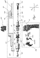
Figure 1 : is a schematic exploded view partially cross sectioned of the inoculation apparatus according to the present invention and a hand-grip which can be associated with said apparatus; -
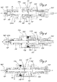
Figure 2 : is a longitudinal section, along a vertical axial plane, of the apparatus according toFig. 1 in the assembled condition; -
Figure 3 : is a longitudinal section, similar to that ofFig. 2 , of the apparatus during filling; -
Figure 4 : is a cross-section, similar to that of -
Fig. 2 , of the apparatus during dispensing; -
Figure 5 : is a cross-section, similar to that of -
Fig. 2 , of the apparatus during rearming; -
Figure 6 : shows the apparatus according to the invention assembled with a hand-grip for gripping and operation by the user; -
Figure 7 : shows a longitudinally sectioned view of a variation of embodiment of the means for adjusting the inoculation force of the apparatus according to the present invention; and -
Figure 8 : shows a view, similar to that ofFig. 7 , of an apparatus associated with a further embodiment of a hand-grip for the user. - As shown in
Figs. 1 and2 the following axes are assumed solely for the sake of easier description and without a limiting meaning: a set of three axes having, respectively, a longitudinal axial direction X-X, corresponding to the direction of axial extension of the apparatus, transverse/radial direction Y-Y orthogonal to the preceding direction, and vertical direction Z-Z, orthogonal to the plane formed by the other two directions, as well as a front end corresponding to the end for discharging of the medicament and a rear end opposite to said front end. - In addition to this, for the purposes of the present patent, "firing" is understood as meaning the actions which cause the returning of the medicament and "arming" is understood as meaning the actions which cause the resetting of a apparatus to the firing condition.
- As shown, an
apparatus 100 for transdermal inoculation of medicaments and the like according to the invention comprises : - -) a cylindrical mono-
body 110 forming a first, rear,chamber 111 of given diameter and a second, front,chamber 112 for metering the medicament to be injected, having a smaller diameter than that of thefirst chamber 111, said chambers extending coaxially in the longitudinal direction and being connected together by means of anintermediate chamber 113 having a diameter in between the two said diameters; the cylindrical body has an inlet 111d, which only by way of example is shown as being axial, for supplying to thefirst chamber 111 compressed air acting in a direction opposite to the direction of inoculation and firing. - -) the
rear chamber 111 is delimited at the rear by a first, rear,closing member 114 of the cylindrical mono-body 110, which has a coaxial through-hole 114a and which is mounted on thebody 110 for example by means of a screw 114b/female thread 111b connection; - On its surface facing the inside of the
chamber 111, thefirst closing member 114 has a seat 114c for receiving the end of aspring 115, the other end of which acts against a correspondingouter bearing surface 116a of ahollow piston 116, in turn arranged coaxially and axially slidably inside therear chamber 111; the other surface of the piston also has, mounted thereon, an annular seal 116b, preferably of the lip type, for ensuring a relative sealing action for the air A supplied to thechamber 111 through the associated inlet 111d. - -) inside the
hollow piston 116 there is, coaxially arranged, ahollow sleeve 117 for carryingballs 118, which has an axially rear part with an outer diameter corresponding to the inner diameter of anopen hole 116a in therear end surface 116d of thepiston 116 and a front part with an outer diameter corresponding to the inner diameter of thepiston 116; internally thesleeve 117 has anannular projection 117a and an annular seat 117b which are arranged axially in succession from the front end to the rear end of the apparatus and are respectively designed to interfere with and partially contain a plurality ofballs 118 designed to interact in the transverse/radial direction with aplunger 150 as will emerge more clearly below; - -) the
sleeve 117 is kept axially in bearing contact against the inner rear end of thehollow piston 116 by a substantially T-shaped thruster 119 with ashank 119a having: an outer diameter corresponding to the inner diameter of thehollow sleeve 117, inside which it penetrates partially in the axial direction, and ahead 119b with an outer diameter such as to make bearing contact inside acorresponding seat 116f of the base of saidpiston 116; acoaxial thrust spring 120 substantially concentric with thespring 115 acting against thepiston 116 being arranged between thehead 119b of the thruster and the front base of thesleeve 117; as shown, once assembly has been completed, afree space 121 remains between the free end of the shank of the T inside the recess and the rear end surface of thesleeve 117. - On the free front end of the said
second chamber 112 there is mounted anozzle 140 which is provided with an associatedoutlet hole 140a and has, arranged inside it, aball 141 which is pushed by aspring 141a towards arear duct 142 connecting the nozzle to thefront chamber 112 so that the duct is normally closed. - An
adapter 145 with coaxialinner seat 143, inside which the front end of aplunger 150 described below may penetrate, is arranged between thenozzle 140 and the front end of the cylindrical body inside which thefront chamber 112 is formed. - A
duct 143, which is radial in the example, for supplying the medicament M to be inoculated also leads into thefront chamber 112. - Coaxially with the
cylindrical body 110 and inside it, afiring plunger 150 is mounted thereon, said plunger being assembled at the rear inside anipple 151 which is screwed onto the female thread 114c of the through-hole of themember 114 for closing thefirst chamber 111; in greater detail, the rear part of theplunger 150 has anannular projection 152 with an outer diameter substantially corresponding to the inner diameter of thenipple 151 so as to form an end-of-travel element making contact against thefront wall 151a of the nipple provided with a through-hole 151b having an outer diameter corresponding to the outer diameter of theplunger 150; theannular projection 152 of theplunger 150 forms a support base for one end of afiring spring 153, the other end of which reacts against amember 154 for closing the rear of thenipple 151. Preferably, said closing member consists of aring 154 for adjusting the compression of the spring, which is screwed onto the second thread 151b of said nipple; said ring having a rear hole for allowing the end of theplunger 150 to protrude outwards. - In a zone thereof axially corresponding to the axial position of the
sleeve 117 carrying theballs 118, the plunger has anannular groove 155 designed to cooperate with the saidballs 118 so as to cause coupling/release of the plunger with/from thepiston 116. - In the rest condition the
front end 150a of theplunger 150 bears axially against theduct 142 of thenozzle 140. - With reference to this configuration the operating principle of the apparatus is now explained:
- -) in the rest and cycle start conditions (
Fig. 2 ) the three springs 115,120,153 all act with a thrusting force, so as to keep, respectively:- the
piston 116 in the end-of-travel position towards the front end of thechamber 111 so that thethruster 119 bears against the annular head 13b of thefront closing member 123, - the
sleeve 117 in bearing contact against the rear surface of thepiston 116 so that its rear part protrudes partially from the said piston, - the
plunger 150 pushed forward with the end-of-travel projection 152 against thefront end wall 151a of thenipple 151; - in this way the
annular seat 155 of theplunger 150 is arranged axially aligned with theballs 118 kept radially pushed towards the longitudinal axis X-X by theprojection 117a of the sleeve 117: theplunger 150 is therefore rigidly locked to thepiston 116;
- the
- -) by supplying air A (
Fig. 3 ) to thechamber 111 to act in a direction opposite to the firing direction and with a pressure such as to overcome the thrust of thesprings piston 116 and theplunger 150 are simultaneously displaced towards the rear of thechamber 111 until thesleeve 117 makes bearing contact axially with thenipple 151 of therear closing member 114; retraction of theplunger 150 also creates a vacuum inside thefront chamber 112 which causes the suction of the predefined quantity of medicament M from a respective storage container (not shown); - -) continuing with supplying of the air A (
Fig. 4 ), the piston continues its axial travel until it comes into contact against theclosing member 114, causing simultaneously:- retraction, towards the front, of the
sleeve 117 which consequently brings its annular seat 117b into an axial position corresponding to that of theballs 118 which are thus allowed to come out radially from theannular seat 155 of theplunger 150 which is now disengaged from the condition locked together with thepiston 116; - -) the
plunger 150, freed from engagement with thepiston 116, is pushed violently forwards (fig. 5 ) by the thrust of the previously compressedspring 153, causing:- the medicament M to be discharged through the
nozzle 140, - the return to the initial position (
Fig. 2 ) of the apparatus, with rearming of the plunger which is ready for a second inoculation cycle.
- the medicament M to be discharged through the
- retraction, towards the front, of the
- Correct designing of the dimensions of the various component parts and in particular the volumes of the first and second chambers and the reaction force of the three springs will also allow the aspiration/injection of a precise and predefined amount of medicament M; in addition, adjustment, by means of the
ring nut 154, of the force of thespring 153 acting on theplunger 150 also allows adjustment of the penetration force and the injection depth of the medicament depending on the hardness of the hide and the size of the animal. According to a preferred embodiment the rear free end of theplunger 150 hasannular notches 150g, preferably marked with values of a numerical scale which correspond to different inoculation pressure values related to the different ages and type of animal and determined a priori on the basis of test measurements and which provide the user with a means for intuitive calibration of the thrusting force of the plunger. - It is therefore clear how the apparatus according to the invention is easy and inexpensive to implement, manage, use and maintain, also by personnel who are not particularly skilled, and can be supplied with a fluid, such as compressed air, obtainable at a low cost by means of an ordinary compressor which can be found and installed in any location and at a negligble cost, without depending on any external service.
- In addition, in the apparatus according to the invention, the inoculating action is determined by the force imparted by the spring acting on the plunger, while subsequent rearming is performed by means of the supply fluid (compressed air), therefore eliminating the manual effort on the part of the operator with a consequent reduction in the fatigue and improved performance.
- Moreover, owing to the particular concentric arrangement of the cylindrical mono-body, the piston with associated arming springs and the radial ball carrier sleeve, the longitudinal dimensions of the apparatus may be kept small, thus resulting in better balance and therefore precision of the apparatus and a reduction in the fatigue of the operator, this fatigue being one of the main causes of imprecise or unsuccessful inoculation. Moreover, with the apparatus according to the invention, use of the inoculation needle is eliminated also for the administration of large quantities of medicament and this results in the further advantages comprising:
- the substantial elimination of the risk of transmission of infections between animals, since, when operating in large numbers, it is not possible to replace every time the needle following use with conventional methods (iatrogenic transmission);
- guarantee of the sterility of the drug or vaccine which is injected;
- a significant reduction in the traumatic effect caused by the introduction of the needle into the body of the animal, with frequent haemorrhages and in particular bacterial infections attributable to dirty or blunt needles (abscesses which are also responsible for a significant economic loss since they result in devaluation of the carcass in terms of product quality);
- elimination of the risk of broken needles remaining in the carcasses, together with the extremely serious consequences for the consumer in the light of the increasingly rigorous food safety regulations; it should be remembered that all the major slaughterhouses must be equipped with metal detectors in order to eliminate this risk.
- reduction of the stress affecting the animal with obvious benefits for the same;
- elimination of the risk of injury for operators owing to accidental injections, in view also of the high production demands which are characteristic of intensive livestock rearing;
- major reduction in the muscular force required of the operator, this being replaced by the mechanical work performed by the compressed air.
- As shown in
Fig. 6 andFig. 1 , a further embodiment of the apparatus according to the invention is envisaged and comprises an anatomical hand-grip 200 composed of: - a butt 210 with a top head-
piece 211 which houses internally avalve 212 for supplying the air A; thevalve 212 is opened by atrigger 213 protected by aguard 214 which acts on aspindle 213a which opens the duct supplying the compressed air from a corresponding storage container/compressor (not shown); theapparatus 100 is also fixed to the head-piece 211 by means of a bridge-piece 220 (Fig. 1 ) which can be screwed in the vertical direction Z-Z onto said head-piece 211. - As shown in
Fig. 7 , it is envisaged that in a further embodiment thenipple 151 is coaxially inserted inside an axial extension 1111 of thebody 111 and that the axial length of the rear part of theplunger 150 is reduced so as to occupy only a part of the inside of said nipple, so that the other, rear, part may contain theshank 1155a of athruster 1155, the head 1155b of which external to thenipple 151 forms the bearing surface for the rear end of thespring 153. - The
presser 1155 is displaced by theend 1154a of alever 1154 rotating about a transverse pin 1154b; conveniently theend 1154a of thelever 1154 acting on thepresser 1155 is formed as a cam with a plurality of flat surfaces 1154c which are arranged at different inclinations so as to determine different thrusting forces of thepresser 155 and therefore different compressions of thespring 153 acting during firing on theplunger 150 with consequent different forces for injection of medicament. -
Fig. 8 shows a further embodiment of the hand-grip 1200 which can be associated with the inoculation apparatus 1100 according toFig. 7 ; this embodiment has afiring trigger 1213 and asafety locking element 1214 which, only when pressed, releases the supply of air A to the apparatus. - In these configurations the apparatus thus becomes a convenient, light and functional transdermal inoculation gun designed to ensure a high inoculation performance.
- Although described in connection with the use for animals, if designed with the appropriate dimensions the apparatus may also be used for administration operations carried out on humans. Although described in connection with a number of embodiments and a number of preferred examples of embodiment of the invention, it is understood that the scope of protection of the present patent is determined solely by the claims below.
Claims (8)
- Apparatus for transdermal inoculation of medicaments or the like, extending in a longitudinal axial direction (X-X) between a front end for discharging the medicament in a firing direction and a rear end opposite to the front end, comprising:• a cylindrical mono-body (110) forming- a rear chamber (111) of given diameter with a front end surface provided with a front inlet (111d) for air (A) supplied under pressure to act in a direction opposite to the firing direction;- a front chamber (112) with a diameter smaller than that of the rear chamber (111) and provided with an associated inlet (143) for the medicament (M), said chambers extending coaxially in the longitudinal direction (X-X) and being connected together by means of an intermediate chamber (113) having a diameter in between the diameter of the other two chambers (111;112);- a first rear closing member (114) for closing the cylindrical mono-body (110), which delimits at the rear the rear chamber (111) and has a coaxial through-hole (114a) with female thread (114c);- a second front closing member (123), which delimits at the front the rear chamber (111) and has an annular head (123b) able to enter into bearing contact with the front end surface of the rear chamber (111) and which has a through-hole (123a) passing through it;• an arming hollow piston (116) coaxially arranged in a sealed manner and axially slidably inside the rear chamber (111), the piston (116) comprising:- an outer bearing surface (116a),- a rear end surface (116d),- a hole (116c) formed in the rear end surface (116d),- a base with a seat (116f);• a first spring (115) arranged between the outer bearing surface (116a) of the piston (116) and the first rear closing member (114)• a hollow sleeve (117) which is coaxially inserted inside the piston (116) and which has- an axially rear part with an outer diameter corresponding to the inner diameter of the hole (116c) formed in the rear end surface (116d) of the piston (116);- a front part with an outer diameter corresponding to the inner diameter of the piston (116);- internally the sleeve (117) has an annular projection (117a) for interfering with a plurality of balls (118) and an annular seat (117b) for partially containing the plurality of balls (118), which are arranged axially one after another from the front end towards the rear end of the apparatus;• a substantially T-shaped thruster (119) with:- a shank (119a) having an outer diameter corresponding to the inner diameter of the hollow sleeve (117) inside which it penetrates partially in the axial direction and- a head (119b) with an outer diameter such as to make bearing contact inside the corresponding seat (116f) of the base of the piston (116);• a thrust spring (120) arranged between the head (119b) of the thruster (119) and the front part of the sleeve (117) and concentrically with respect to the spring (115) acting on the arming piston;• a nozzle (140) which is provided with an associated outlet hole (140a) and has, arranged inside it, a ball (141) which is pushed by a spring (141a) towards a rear duct (142) connecting the nozzle to the front chamber (112) so that the duct is normally closed;• a firing plunger (150) coaxially contained inside the cylindrical body (110) and provided with a rear part which has an annular projection (152) of given outer diameter;• a nipple (151) screwed onto the female thread (114c) of the through-hole of the closing member (114), the nipple having- an inner diameter substantially corresponding to the outer diameter of the annular projection (152) of the rear part of the plunger (150);- a front wall (151a) having a through-hole (151b) with an inner diameter corresponding to the outer diameter of the plunger (150);- a rear closing member (154;1154);• a firing spring (153) arranged between the rear closing member (154;1154) of the nipple and the annular projection (152) of the firing plunger (150) acting with a thrust thereon;wherein the firing plunger (150) is provided with an annular recess (155) suitable for cooperating with the said plurality of balls (118) so as to cause coupling/release of the plunger (150) with/from the piston (116), so that in a rest position of the apparatus, the plunger (150) is pushed forward with the end-of-travel annular projection (152) against the front end wall (151a)of the nipple (151), the annular recess (155)of the plunger (150) being arranged axially aligned with the plurality of balls (118)that are kept radially pushed towards the longitudinal axis (X-X)by the annular projection (117a) of the sleeve (117), such that the plunger (150) is rigidly coupled with the piston (116); and
wherein by supplying air A to the rear chamber (111) via the inlet with a pressure such as to overcome the thrust of the first (115) and firing (153) springs, the piston (116) and the plunger (150) are simultaneously displaced from the rest condition towards the rear of the rear chamber (111) until the sleeve (117) makes bearing contact axially with the nipple (151) of the rear closing member (114), retraction of the plunger (150) creating a vacuum inside the front chamber (112) which causes suction of a predefined quantity of medicament M;
and wherein, continuing with supplying of the air (A), the plunger (150) becomes freed from engagement with the piston (116), and is thus pushed violently forwards by the thrust of the previously compressed firing spring (153), causing the medicament (M) to be discharged through the nozzle (140). - Apparatus according to Claim 1, characterized in that said member closing the rear end of the nipple (151) is formed by a ring nut (154) screwed onto a rear thread (151b) of the said nipple.
- Apparatus according to Claim 2, characterized in that said ring nut has a rear hole for allowing the rear end of the plunger (150) to protrude externally.
- Apparatus according to Claim 3, characterized in that the rear end of the plunger (150) has annular notches (150g) marked with values of a numerical scale corresponding to different inoculation pressure values.
- Apparatus according to Claim 1, characterized in that the body (111) has an axial extension (1111) inside which the nipple (151) is coaxially inserted and that the axial length of the rear part of the plunger (150) is sufficiently small to occupy only an axial part of the inside of the said nipple.
- Apparatus according to Claim 5, characterized in that it comprises a presser (1155) which has a shank (1155a) contained inside the inner rear part of the nipple (151) and the head (1155b) of which is situated outside the nipple (151) and forms the bearing surface for the rear end of the spring (153).
- Apparatus according to Claim 6, characterized in that it comprises means for adjusting the compression of the firing spring (153), comprising a lever (1154) which is rotatable about a transverse pin (1154b) and the end (1154a) of which acting on the presser (1155) is shaped in the manner of a cam with a plurality of flat surfaces (1154c) arranged at different inclinations.
- Apparatus according to any one of the preceding claims, characterized in that it comprises a hand-grip (200;1200) with associated valve (212) for supplying the compressed air (A), an operating trigger (213;1213) and safety element (214;1214) for preventing accidental firing.
Applications Claiming Priority (1)
| Application Number | Priority Date | Filing Date | Title |
|---|---|---|---|
| IT002067A ITMI20132067A1 (en) | 2013-12-11 | 2013-12-11 | EQUIPMENT FOR THE TRANSDERMIC INOCULATION OF MEDICINATIONS |
Publications (2)
| Publication Number | Publication Date |
|---|---|
| EP2896420A1 EP2896420A1 (en) | 2015-07-22 |
| EP2896420B1 true EP2896420B1 (en) | 2020-05-27 |
Family
ID=49958576
Family Applications (1)
| Application Number | Title | Priority Date | Filing Date |
|---|---|---|---|
| EP14196904.8A Active EP2896420B1 (en) | 2013-12-11 | 2014-12-09 | Apparatus for needleless transdermal inoculation of medicaments |
Country Status (3)
| Country | Link |
|---|---|
| EP (1) | EP2896420B1 (en) |
| ES (1) | ES2808773T3 (en) |
| IT (1) | ITMI20132067A1 (en) |
Family Cites Families (8)
| Publication number | Priority date | Publication date | Assignee | Title |
|---|---|---|---|---|
| GB766431A (en) * | 1953-02-11 | 1957-01-23 | Nat Res Dev | Improvements relating to hypodermic injection apparatus |
| US3057349A (en) * | 1959-12-14 | 1962-10-09 | Ismach Aaron | Multi-dose jet injection device |
| US4103684A (en) * | 1976-12-30 | 1978-08-01 | Aaron Ismach | Hydraulically powered hypodermic injector with adapters for reducing and increasing fluid injection force |
| DE3115376A1 (en) * | 1981-04-16 | 1982-12-16 | Hoechst Ag, 6000 Frankfurt | NEEDLE-FREE INJECTION DEVICE |
| FR2629706B1 (en) * | 1988-04-11 | 1992-05-22 | Accaries Claude | LIQUID INJECTION APPARATUS, PARTICULARLY FOR USE IN DENTAL CARE |
| US6939319B1 (en) * | 2002-11-20 | 2005-09-06 | Conrad Anstead | Process and device for single use, needle-free intradermal, subcutaneous, or intramuscular injections |
| US8821434B2 (en) | 2010-10-07 | 2014-09-02 | Massachusetts Institute Of Technology | Delivery of a solid body and/or a fluid using a linear Lorentz-force actuated needle-free jet injection system |
| RU2587011C2 (en) | 2011-01-10 | 2016-06-10 | Зодженикс, Инк. | Improved needle-free injectors |
-
2013
- 2013-12-11 IT IT002067A patent/ITMI20132067A1/en unknown
-
2014
- 2014-12-09 ES ES14196904T patent/ES2808773T3/en active Active
- 2014-12-09 EP EP14196904.8A patent/EP2896420B1/en active Active
Non-Patent Citations (1)
| Title |
|---|
| None * |
Also Published As
| Publication number | Publication date |
|---|---|
| EP2896420A1 (en) | 2015-07-22 |
| ES2808773T3 (en) | 2021-03-01 |
| ITMI20132067A1 (en) | 2015-06-12 |
Similar Documents
| Publication | Publication Date | Title |
|---|---|---|
| US5549560A (en) | Apparatus and method for injecting a pharmaceutical preparation in solid form | |
| EP1474192B1 (en) | Needleless injector | |
| KR20120116428A (en) | Needleless injector | |
| AU2011329575B2 (en) | Medicament delivery device | |
| US20040158195A1 (en) | Needle-free mass injection device | |
| CN107397606B (en) | A kind of veterinary syringe | |
| US10434257B2 (en) | Powered injection device for delivering multiple liquid formulations, including vaccines | |
| US20040129803A1 (en) | Triggering means for a pressure jet injector | |
| EP2896420B1 (en) | Apparatus for needleless transdermal inoculation of medicaments | |
| CN106255521B (en) | Medicament delivery device | |
| CN102512733A (en) | Disposable needleless injector | |
| KR200488129Y1 (en) | Vaccine markers | |
| AU2002332125B2 (en) | Jet injector with hand piece | |
| CN204932479U (en) | Needleless injector | |
| AU2019203731B2 (en) | An Injector | |
| US20240001043A1 (en) | Medication delivery device | |
| CN115804890B (en) | Fuel-powered needleless continuous injection device and method | |
| EP1225842B1 (en) | Apparatus for the inoculation of medications in animals | |
| JP2022528596A (en) | Dosing device for administering liquids |
Legal Events
| Date | Code | Title | Description |
|---|---|---|---|
| PUAI | Public reference made under article 153(3) epc to a published international application that has entered the european phase |
Free format text: ORIGINAL CODE: 0009012 |
|
| 17P | Request for examination filed |
Effective date: 20141209 |
|
| AK | Designated contracting states |
Kind code of ref document: A1 Designated state(s): AL AT BE BG CH CY CZ DE DK EE ES FI FR GB GR HR HU IE IS IT LI LT LU LV MC MK MT NL NO PL PT RO RS SE SI SK SM TR |
|
| AX | Request for extension of the european patent |
Extension state: BA ME |
|
| 17P | Request for examination filed |
Effective date: 20160120 |
|
| RBV | Designated contracting states (corrected) |
Designated state(s): AL AT BE BG CH CY CZ DE DK EE ES FI FR GB GR HR HU IE IS IT LI LT LU LV MC MK MT NL NO PL PT RO RS SE SI SK SM TR |
|
| STAA | Information on the status of an ep patent application or granted ep patent |
Free format text: STATUS: EXAMINATION IS IN PROGRESS |
|
| 17Q | First examination report despatched |
Effective date: 20180810 |
|
| GRAP | Despatch of communication of intention to grant a patent |
Free format text: ORIGINAL CODE: EPIDOSNIGR1 |
|
| STAA | Information on the status of an ep patent application or granted ep patent |
Free format text: STATUS: GRANT OF PATENT IS INTENDED |
|
| INTG | Intention to grant announced |
Effective date: 20191108 |
|
| INTG | Intention to grant announced |
Effective date: 20191113 |
|
| GRAS | Grant fee paid |
Free format text: ORIGINAL CODE: EPIDOSNIGR3 |
|
| GRAJ | Information related to disapproval of communication of intention to grant by the applicant or resumption of examination proceedings by the epo deleted |
Free format text: ORIGINAL CODE: EPIDOSDIGR1 |
|
| GRAL | Information related to payment of fee for publishing/printing deleted |
Free format text: ORIGINAL CODE: EPIDOSDIGR3 |
|
| STAA | Information on the status of an ep patent application or granted ep patent |
Free format text: STATUS: EXAMINATION IS IN PROGRESS |
|
| GRAR | Information related to intention to grant a patent recorded |
Free format text: ORIGINAL CODE: EPIDOSNIGR71 |
|
| STAA | Information on the status of an ep patent application or granted ep patent |
Free format text: STATUS: GRANT OF PATENT IS INTENDED |
|
| GRAJ | Information related to disapproval of communication of intention to grant by the applicant or resumption of examination proceedings by the epo deleted |
Free format text: ORIGINAL CODE: EPIDOSDIGR1 |
|
| STAA | Information on the status of an ep patent application or granted ep patent |
Free format text: STATUS: EXAMINATION IS IN PROGRESS |
|
| INTC | Intention to grant announced (deleted) | ||
| GRAR | Information related to intention to grant a patent recorded |
Free format text: ORIGINAL CODE: EPIDOSNIGR71 |
|
| STAA | Information on the status of an ep patent application or granted ep patent |
Free format text: STATUS: GRANT OF PATENT IS INTENDED |
|
| GRAA | (expected) grant |
Free format text: ORIGINAL CODE: 0009210 |
|
| STAA | Information on the status of an ep patent application or granted ep patent |
Free format text: STATUS: THE PATENT HAS BEEN GRANTED |
|
| AK | Designated contracting states |
Kind code of ref document: B1 Designated state(s): AL AT BE BG CH CY CZ DE DK EE ES FI FR GB GR HR HU IE IS IT LI LT LU LV MC MK MT NL NO PL PT RO RS SE SI SK SM TR |
|
| INTG | Intention to grant announced |
Effective date: 20200420 |
|
| REG | Reference to a national code |
Ref country code: GB Ref legal event code: FG4D |
|
| REG | Reference to a national code |
Ref country code: CH Ref legal event code: EP |
|
| REG | Reference to a national code |
Ref country code: AT Ref legal event code: REF Ref document number: 1273880 Country of ref document: AT Kind code of ref document: T Effective date: 20200615 |
|
| REG | Reference to a national code |
Ref country code: DE Ref legal event code: R096 Ref document number: 602014065849 Country of ref document: DE |
|
| REG | Reference to a national code |
Ref country code: LT Ref legal event code: MG4D |
|
| PG25 | Lapsed in a contracting state [announced via postgrant information from national office to epo] |
Ref country code: IS Free format text: LAPSE BECAUSE OF FAILURE TO SUBMIT A TRANSLATION OF THE DESCRIPTION OR TO PAY THE FEE WITHIN THE PRESCRIBED TIME-LIMIT Effective date: 20200927 Ref country code: NO Free format text: LAPSE BECAUSE OF FAILURE TO SUBMIT A TRANSLATION OF THE DESCRIPTION OR TO PAY THE FEE WITHIN THE PRESCRIBED TIME-LIMIT Effective date: 20200827 Ref country code: FI Free format text: LAPSE BECAUSE OF FAILURE TO SUBMIT A TRANSLATION OF THE DESCRIPTION OR TO PAY THE FEE WITHIN THE PRESCRIBED TIME-LIMIT Effective date: 20200527 Ref country code: GR Free format text: LAPSE BECAUSE OF FAILURE TO SUBMIT A TRANSLATION OF THE DESCRIPTION OR TO PAY THE FEE WITHIN THE PRESCRIBED TIME-LIMIT Effective date: 20200828 Ref country code: LT Free format text: LAPSE BECAUSE OF FAILURE TO SUBMIT A TRANSLATION OF THE DESCRIPTION OR TO PAY THE FEE WITHIN THE PRESCRIBED TIME-LIMIT Effective date: 20200527 Ref country code: SE Free format text: LAPSE BECAUSE OF FAILURE TO SUBMIT A TRANSLATION OF THE DESCRIPTION OR TO PAY THE FEE WITHIN THE PRESCRIBED TIME-LIMIT Effective date: 20200527 Ref country code: PT Free format text: LAPSE BECAUSE OF FAILURE TO SUBMIT A TRANSLATION OF THE DESCRIPTION OR TO PAY THE FEE WITHIN THE PRESCRIBED TIME-LIMIT Effective date: 20200928 |
|
| REG | Reference to a national code |
Ref country code: NL Ref legal event code: MP Effective date: 20200527 |
|
| PG25 | Lapsed in a contracting state [announced via postgrant information from national office to epo] |
Ref country code: RS Free format text: LAPSE BECAUSE OF FAILURE TO SUBMIT A TRANSLATION OF THE DESCRIPTION OR TO PAY THE FEE WITHIN THE PRESCRIBED TIME-LIMIT Effective date: 20200527 Ref country code: BG Free format text: LAPSE BECAUSE OF FAILURE TO SUBMIT A TRANSLATION OF THE DESCRIPTION OR TO PAY THE FEE WITHIN THE PRESCRIBED TIME-LIMIT Effective date: 20200827 Ref country code: HR Free format text: LAPSE BECAUSE OF FAILURE TO SUBMIT A TRANSLATION OF THE DESCRIPTION OR TO PAY THE FEE WITHIN THE PRESCRIBED TIME-LIMIT Effective date: 20200527 Ref country code: LV Free format text: LAPSE BECAUSE OF FAILURE TO SUBMIT A TRANSLATION OF THE DESCRIPTION OR TO PAY THE FEE WITHIN THE PRESCRIBED TIME-LIMIT Effective date: 20200527 |
|
| REG | Reference to a national code |
Ref country code: AT Ref legal event code: MK05 Ref document number: 1273880 Country of ref document: AT Kind code of ref document: T Effective date: 20200527 |
|
| PG25 | Lapsed in a contracting state [announced via postgrant information from national office to epo] |
Ref country code: AL Free format text: LAPSE BECAUSE OF FAILURE TO SUBMIT A TRANSLATION OF THE DESCRIPTION OR TO PAY THE FEE WITHIN THE PRESCRIBED TIME-LIMIT Effective date: 20200527 Ref country code: NL Free format text: LAPSE BECAUSE OF FAILURE TO SUBMIT A TRANSLATION OF THE DESCRIPTION OR TO PAY THE FEE WITHIN THE PRESCRIBED TIME-LIMIT Effective date: 20200527 |
|
| PG25 | Lapsed in a contracting state [announced via postgrant information from national office to epo] |
Ref country code: EE Free format text: LAPSE BECAUSE OF FAILURE TO SUBMIT A TRANSLATION OF THE DESCRIPTION OR TO PAY THE FEE WITHIN THE PRESCRIBED TIME-LIMIT Effective date: 20200527 Ref country code: AT Free format text: LAPSE BECAUSE OF FAILURE TO SUBMIT A TRANSLATION OF THE DESCRIPTION OR TO PAY THE FEE WITHIN THE PRESCRIBED TIME-LIMIT Effective date: 20200527 Ref country code: SM Free format text: LAPSE BECAUSE OF FAILURE TO SUBMIT A TRANSLATION OF THE DESCRIPTION OR TO PAY THE FEE WITHIN THE PRESCRIBED TIME-LIMIT Effective date: 20200527 Ref country code: DK Free format text: LAPSE BECAUSE OF FAILURE TO SUBMIT A TRANSLATION OF THE DESCRIPTION OR TO PAY THE FEE WITHIN THE PRESCRIBED TIME-LIMIT Effective date: 20200527 Ref country code: CZ Free format text: LAPSE BECAUSE OF FAILURE TO SUBMIT A TRANSLATION OF THE DESCRIPTION OR TO PAY THE FEE WITHIN THE PRESCRIBED TIME-LIMIT Effective date: 20200527 Ref country code: RO Free format text: LAPSE BECAUSE OF FAILURE TO SUBMIT A TRANSLATION OF THE DESCRIPTION OR TO PAY THE FEE WITHIN THE PRESCRIBED TIME-LIMIT Effective date: 20200527 |
|
| PG25 | Lapsed in a contracting state [announced via postgrant information from national office to epo] |
Ref country code: SK Free format text: LAPSE BECAUSE OF FAILURE TO SUBMIT A TRANSLATION OF THE DESCRIPTION OR TO PAY THE FEE WITHIN THE PRESCRIBED TIME-LIMIT Effective date: 20200527 Ref country code: PL Free format text: LAPSE BECAUSE OF FAILURE TO SUBMIT A TRANSLATION OF THE DESCRIPTION OR TO PAY THE FEE WITHIN THE PRESCRIBED TIME-LIMIT Effective date: 20200527 |
|
| REG | Reference to a national code |
Ref country code: ES Ref legal event code: FG2A Ref document number: 2808773 Country of ref document: ES Kind code of ref document: T3 Effective date: 20210301 |
|
| REG | Reference to a national code |
Ref country code: DE Ref legal event code: R097 Ref document number: 602014065849 Country of ref document: DE |
|
| PLBE | No opposition filed within time limit |
Free format text: ORIGINAL CODE: 0009261 |
|
| STAA | Information on the status of an ep patent application or granted ep patent |
Free format text: STATUS: NO OPPOSITION FILED WITHIN TIME LIMIT |
|
| 26N | No opposition filed |
Effective date: 20210302 |
|
| PG25 | Lapsed in a contracting state [announced via postgrant information from national office to epo] |
Ref country code: SI Free format text: LAPSE BECAUSE OF FAILURE TO SUBMIT A TRANSLATION OF THE DESCRIPTION OR TO PAY THE FEE WITHIN THE PRESCRIBED TIME-LIMIT Effective date: 20200527 |
|
| REG | Reference to a national code |
Ref country code: CH Ref legal event code: PL |
|
| GBPC | Gb: european patent ceased through non-payment of renewal fee |
Effective date: 20201209 |
|
| PG25 | Lapsed in a contracting state [announced via postgrant information from national office to epo] |
Ref country code: MC Free format text: LAPSE BECAUSE OF FAILURE TO SUBMIT A TRANSLATION OF THE DESCRIPTION OR TO PAY THE FEE WITHIN THE PRESCRIBED TIME-LIMIT Effective date: 20200527 |
|
| REG | Reference to a national code |
Ref country code: BE Ref legal event code: MM Effective date: 20201231 |
|
| PG25 | Lapsed in a contracting state [announced via postgrant information from national office to epo] |
Ref country code: IE Free format text: LAPSE BECAUSE OF NON-PAYMENT OF DUE FEES Effective date: 20201209 Ref country code: LU Free format text: LAPSE BECAUSE OF NON-PAYMENT OF DUE FEES Effective date: 20201209 |
|
| PG25 | Lapsed in a contracting state [announced via postgrant information from national office to epo] |
Ref country code: GB Free format text: LAPSE BECAUSE OF NON-PAYMENT OF DUE FEES Effective date: 20201209 Ref country code: CH Free format text: LAPSE BECAUSE OF NON-PAYMENT OF DUE FEES Effective date: 20201231 Ref country code: LI Free format text: LAPSE BECAUSE OF NON-PAYMENT OF DUE FEES Effective date: 20201231 |
|
| PG25 | Lapsed in a contracting state [announced via postgrant information from national office to epo] |
Ref country code: TR Free format text: LAPSE BECAUSE OF FAILURE TO SUBMIT A TRANSLATION OF THE DESCRIPTION OR TO PAY THE FEE WITHIN THE PRESCRIBED TIME-LIMIT Effective date: 20200527 Ref country code: MT Free format text: LAPSE BECAUSE OF FAILURE TO SUBMIT A TRANSLATION OF THE DESCRIPTION OR TO PAY THE FEE WITHIN THE PRESCRIBED TIME-LIMIT Effective date: 20200527 Ref country code: CY Free format text: LAPSE BECAUSE OF FAILURE TO SUBMIT A TRANSLATION OF THE DESCRIPTION OR TO PAY THE FEE WITHIN THE PRESCRIBED TIME-LIMIT Effective date: 20200527 |
|
| PG25 | Lapsed in a contracting state [announced via postgrant information from national office to epo] |
Ref country code: MK Free format text: LAPSE BECAUSE OF FAILURE TO SUBMIT A TRANSLATION OF THE DESCRIPTION OR TO PAY THE FEE WITHIN THE PRESCRIBED TIME-LIMIT Effective date: 20200527 |
|
| PG25 | Lapsed in a contracting state [announced via postgrant information from national office to epo] |
Ref country code: BE Free format text: LAPSE BECAUSE OF NON-PAYMENT OF DUE FEES Effective date: 20201231 |
|
| PGFP | Annual fee paid to national office [announced via postgrant information from national office to epo] |
Ref country code: FR Payment date: 20221214 Year of fee payment: 9 Ref country code: DE Payment date: 20221216 Year of fee payment: 9 |
|
| PGFP | Annual fee paid to national office [announced via postgrant information from national office to epo] |
Ref country code: ES Payment date: 20230102 Year of fee payment: 9 |
|
| P01 | Opt-out of the competence of the unified patent court (upc) registered |
Effective date: 20230313 |
|
| PGFP | Annual fee paid to national office [announced via postgrant information from national office to epo] |
Ref country code: IT Payment date: 20231214 Year of fee payment: 10 |