EP2896383A1 - Signalübertragung mit Kathetergeflechtdrähten - Google Patents
Signalübertragung mit Kathetergeflechtdrähten Download PDFInfo
- Publication number
- EP2896383A1 EP2896383A1 EP15151379.3A EP15151379A EP2896383A1 EP 2896383 A1 EP2896383 A1 EP 2896383A1 EP 15151379 A EP15151379 A EP 15151379A EP 2896383 A1 EP2896383 A1 EP 2896383A1
- Authority
- EP
- European Patent Office
- Prior art keywords
- signal
- braid
- pair
- magnetic field
- insertion tube
- Prior art date
- Legal status (The legal status is an assumption and is not a legal conclusion. Google has not performed a legal analysis and makes no representation as to the accuracy of the status listed.)
- Granted
Links
- 230000008054 signal transmission Effects 0.000 title description 6
- 238000003780 insertion Methods 0.000 claims abstract description 38
- 230000037431 insertion Effects 0.000 claims abstract description 38
- 239000000523 sample Substances 0.000 claims abstract description 31
- 238000000034 method Methods 0.000 claims description 30
- 230000000747 cardiac effect Effects 0.000 claims description 7
- 230000001939 inductive effect Effects 0.000 description 4
- 238000013507 mapping Methods 0.000 description 4
- 238000002679 ablation Methods 0.000 description 3
- 230000006870 function Effects 0.000 description 3
- 239000002184 metal Substances 0.000 description 3
- 230000004044 response Effects 0.000 description 3
- 210000000748 cardiovascular system Anatomy 0.000 description 2
- 238000010586 diagram Methods 0.000 description 2
- 230000005672 electromagnetic field Effects 0.000 description 2
- 210000000056 organ Anatomy 0.000 description 2
- 230000001225 therapeutic effect Effects 0.000 description 2
- 206010003119 arrhythmia Diseases 0.000 description 1
- 238000009954 braiding Methods 0.000 description 1
- 239000003990 capacitor Substances 0.000 description 1
- 229940000032 cardiovascular system drug Drugs 0.000 description 1
- 239000004020 conductor Substances 0.000 description 1
- 230000008878 coupling Effects 0.000 description 1
- 238000010168 coupling process Methods 0.000 description 1
- 238000005859 coupling reaction Methods 0.000 description 1
- 238000003745 diagnosis Methods 0.000 description 1
- 229910003460 diamond Inorganic materials 0.000 description 1
- 239000010432 diamond Substances 0.000 description 1
- 230000004064 dysfunction Effects 0.000 description 1
- 238000001125 extrusion Methods 0.000 description 1
- 238000009413 insulation Methods 0.000 description 1
- 238000002595 magnetic resonance imaging Methods 0.000 description 1
- 239000000463 material Substances 0.000 description 1
- 238000005259 measurement Methods 0.000 description 1
- 230000007246 mechanism Effects 0.000 description 1
- 238000012986 modification Methods 0.000 description 1
- 230000004048 modification Effects 0.000 description 1
- 230000003287 optical effect Effects 0.000 description 1
- 229920000642 polymer Polymers 0.000 description 1
- 230000009467 reduction Effects 0.000 description 1
- 230000002792 vascular Effects 0.000 description 1
Images

Classifications
-
- A—HUMAN NECESSITIES
- A61—MEDICAL OR VETERINARY SCIENCE; HYGIENE
- A61B—DIAGNOSIS; SURGERY; IDENTIFICATION
- A61B5/00—Measuring for diagnostic purposes; Identification of persons
- A61B5/06—Devices, other than using radiation, for detecting or locating foreign bodies ; determining position of probes within or on the body of the patient
- A61B5/061—Determining position of a probe within the body employing means separate from the probe, e.g. sensing internal probe position employing impedance electrodes on the surface of the body
- A61B5/062—Determining position of a probe within the body employing means separate from the probe, e.g. sensing internal probe position employing impedance electrodes on the surface of the body using magnetic field
-
- A—HUMAN NECESSITIES
- A61—MEDICAL OR VETERINARY SCIENCE; HYGIENE
- A61B—DIAGNOSIS; SURGERY; IDENTIFICATION
- A61B34/00—Computer-aided surgery; Manipulators or robots specially adapted for use in surgery
- A61B34/20—Surgical navigation systems; Devices for tracking or guiding surgical instruments, e.g. for frameless stereotaxis
-
- A—HUMAN NECESSITIES
- A61—MEDICAL OR VETERINARY SCIENCE; HYGIENE
- A61B—DIAGNOSIS; SURGERY; IDENTIFICATION
- A61B5/00—Measuring for diagnostic purposes; Identification of persons
- A61B5/02—Detecting, measuring or recording pulse, heart rate, blood pressure or blood flow; Combined pulse/heart-rate/blood pressure determination; Evaluating a cardiovascular condition not otherwise provided for, e.g. using combinations of techniques provided for in this group with electrocardiography or electroauscultation; Heart catheters for measuring blood pressure
- A61B5/02028—Determining haemodynamic parameters not otherwise provided for, e.g. cardiac contractility or left ventricular ejection fraction
-
- A—HUMAN NECESSITIES
- A61—MEDICAL OR VETERINARY SCIENCE; HYGIENE
- A61B—DIAGNOSIS; SURGERY; IDENTIFICATION
- A61B5/00—Measuring for diagnostic purposes; Identification of persons
- A61B5/68—Arrangements of detecting, measuring or recording means, e.g. sensors, in relation to patient
- A61B5/6846—Arrangements of detecting, measuring or recording means, e.g. sensors, in relation to patient specially adapted to be brought in contact with an internal body part, i.e. invasive
- A61B5/6847—Arrangements of detecting, measuring or recording means, e.g. sensors, in relation to patient specially adapted to be brought in contact with an internal body part, i.e. invasive mounted on an invasive device
- A61B5/6851—Guide wires
-
- A—HUMAN NECESSITIES
- A61—MEDICAL OR VETERINARY SCIENCE; HYGIENE
- A61B—DIAGNOSIS; SURGERY; IDENTIFICATION
- A61B5/00—Measuring for diagnostic purposes; Identification of persons
- A61B5/68—Arrangements of detecting, measuring or recording means, e.g. sensors, in relation to patient
- A61B5/6846—Arrangements of detecting, measuring or recording means, e.g. sensors, in relation to patient specially adapted to be brought in contact with an internal body part, i.e. invasive
- A61B5/6847—Arrangements of detecting, measuring or recording means, e.g. sensors, in relation to patient specially adapted to be brought in contact with an internal body part, i.e. invasive mounted on an invasive device
- A61B5/6852—Catheters
-
- A—HUMAN NECESSITIES
- A61—MEDICAL OR VETERINARY SCIENCE; HYGIENE
- A61B—DIAGNOSIS; SURGERY; IDENTIFICATION
- A61B5/00—Measuring for diagnostic purposes; Identification of persons
- A61B5/72—Signal processing specially adapted for physiological signals or for diagnostic purposes
- A61B5/7203—Signal processing specially adapted for physiological signals or for diagnostic purposes for noise prevention, reduction or removal
-
- A—HUMAN NECESSITIES
- A61—MEDICAL OR VETERINARY SCIENCE; HYGIENE
- A61M—DEVICES FOR INTRODUCING MEDIA INTO, OR ONTO, THE BODY; DEVICES FOR TRANSDUCING BODY MEDIA OR FOR TAKING MEDIA FROM THE BODY; DEVICES FOR PRODUCING OR ENDING SLEEP OR STUPOR
- A61M25/00—Catheters; Hollow probes
- A61M25/0009—Making of catheters or other medical or surgical tubes
- A61M25/0012—Making of catheters or other medical or surgical tubes with embedded structures, e.g. coils, braids, meshes, strands or radiopaque coils
-
- A—HUMAN NECESSITIES
- A61—MEDICAL OR VETERINARY SCIENCE; HYGIENE
- A61M—DEVICES FOR INTRODUCING MEDIA INTO, OR ONTO, THE BODY; DEVICES FOR TRANSDUCING BODY MEDIA OR FOR TAKING MEDIA FROM THE BODY; DEVICES FOR PRODUCING OR ENDING SLEEP OR STUPOR
- A61M25/00—Catheters; Hollow probes
- A61M25/01—Introducing, guiding, advancing, emplacing or holding catheters
- A61M25/0105—Steering means as part of the catheter or advancing means; Markers for positioning
- A61M25/0127—Magnetic means; Magnetic markers
-
- A—HUMAN NECESSITIES
- A61—MEDICAL OR VETERINARY SCIENCE; HYGIENE
- A61B—DIAGNOSIS; SURGERY; IDENTIFICATION
- A61B34/00—Computer-aided surgery; Manipulators or robots specially adapted for use in surgery
- A61B34/20—Surgical navigation systems; Devices for tracking or guiding surgical instruments, e.g. for frameless stereotaxis
- A61B2034/2046—Tracking techniques
- A61B2034/2051—Electromagnetic tracking systems
-
- A—HUMAN NECESSITIES
- A61—MEDICAL OR VETERINARY SCIENCE; HYGIENE
- A61B—DIAGNOSIS; SURGERY; IDENTIFICATION
- A61B2562/00—Details of sensors; Constructional details of sensor housings or probes; Accessories for sensors
- A61B2562/02—Details of sensors specially adapted for in-vivo measurements
- A61B2562/0223—Magnetic field sensors
-
- A—HUMAN NECESSITIES
- A61—MEDICAL OR VETERINARY SCIENCE; HYGIENE
- A61B—DIAGNOSIS; SURGERY; IDENTIFICATION
- A61B2562/00—Details of sensors; Constructional details of sensor housings or probes; Accessories for sensors
- A61B2562/12—Manufacturing methods specially adapted for producing sensors for in-vivo measurements
-
- A—HUMAN NECESSITIES
- A61—MEDICAL OR VETERINARY SCIENCE; HYGIENE
- A61M—DEVICES FOR INTRODUCING MEDIA INTO, OR ONTO, THE BODY; DEVICES FOR TRANSDUCING BODY MEDIA OR FOR TAKING MEDIA FROM THE BODY; DEVICES FOR PRODUCING OR ENDING SLEEP OR STUPOR
- A61M25/00—Catheters; Hollow probes
- A61M25/0043—Catheters; Hollow probes characterised by structural features
- A61M25/005—Catheters; Hollow probes characterised by structural features with embedded materials for reinforcement, e.g. wires, coils, braids
-
- Y—GENERAL TAGGING OF NEW TECHNOLOGICAL DEVELOPMENTS; GENERAL TAGGING OF CROSS-SECTIONAL TECHNOLOGIES SPANNING OVER SEVERAL SECTIONS OF THE IPC; TECHNICAL SUBJECTS COVERED BY FORMER USPC CROSS-REFERENCE ART COLLECTIONS [XRACs] AND DIGESTS
- Y10—TECHNICAL SUBJECTS COVERED BY FORMER USPC
- Y10T—TECHNICAL SUBJECTS COVERED BY FORMER US CLASSIFICATION
- Y10T29/00—Metal working
- Y10T29/49—Method of mechanical manufacture
- Y10T29/49002—Electrical device making
- Y10T29/49117—Conductor or circuit manufacturing
Definitions
- the present invention relates generally to intra-body probes, and particularly to methods and systems for transmitting electrical signals in intra-body probes.
- Magnetic field detectors installed near the distal end of catheters are used in medical positioning systems to identify the position of the catheter distal end in the body of a patient.
- the catheter distal end sensor is typically connected to the medical positioning system via cabling traversing the catheter lumen.
- U.S. Patent 7,881,769 whose disclosure is incorporated herein by reference, describes a catheter for performing a medical operation on an organic lumen, the catheter including an elongated member, a medical operational element located at a distal end of the elongated member, an electromagnetic field detector located at the distal end, and a wiring for coupling the electromagnetic field detector with a medical positioning system, wherein the medical positioning system determines the position and orientation of the distal end.
- U.S. Patent Application Number US 2012/0182014 whose disclosure is incorporated herein by reference, describes a magnetic resonance imaging device, which includes an elongate flexible member having a proximal end, a distal end, and a lumen extending between the proximal end and the distal end and a solenoid coil affixed to the distal end of the elongate flexible member, the solenoid coil having a plurality of wire turns, the solenoid coil connected to a twisted-pair of leads extending proximally along the length of the flexible member.
- a connector is disposed at the proximal end of the elongate flexible member, the connector operatively coupled to the twisted-pair of leads.
- a coaxial cable substitutes for the lumen-containing elongate flexible member.
- An embodiment of the present invention provides a probe including an insertion tube, a magnetic field sensor, a dummy load mounted adjacent to the magnetic field sensor, and a braid.
- the braid includes multiple braid wires that traverse a length of the insertion tube. A first pair of the braid wires is connected across the magnetic field sensor, and a second pair of the braid wires is connected across the dummy load.
- the magnetic sensor includes a single-axis sensor.
- the probe includes a cardiac catheter.
- the probe includes a cardiac guide-wire.
- each of the braid wires in the first and second pairs is electrically-insulated from the other braid wires.
- the probe includes an elongate flexible member that is contained within the insertion tube, such that the braid is located between the insertion tube and the elongate flexible member.
- the probe includes circuitry that is configured to cancel interference in a first signal transferred over the first pair using a second signal transferred over the second pair.
- the circuitry is configured to subtract the second signal from the first signal.
- a method for fabricating a probe including mounting a magnetic field sensor and a dummy load adjacent to one another in an insertion tube.
- a braid is placed along the insertion tube, the braid including multiple braid wires so as to traverse a length of the insertion tube.
- a first pair of the braid wires is connected across the magnetic field sensor, and a second pair of the braid wires is connected across the dummy load.
- a method for position tracking including inserting into a living body a probe, which includes an insertion tube, a magnetic field sensor, a dummy load mounted adjacent to the magnetic field sensor, and a braid including multiple braid wires that traverse a length of the insertion tube.
- a first pair of the braid wires is connected across the magnetic field sensor, and a second pair of the braid wires is connected across the dummy load.
- a magnetic field is applied to the living body.
- a first signal is measured across the first pair.
- a second signal is measured across the second pair. The second signal is applied to the first signal so as to remove interference from the first signal.
- a position of the magnetic field sensor in the living body is computed from the first signal after removing the interference.
- applying the second signal to the first signal includes subtracting the second signal from the first signal.
- a position tracking system including a probe and an external subsystem.
- the probe is inserted into a living body and includes an insertion tube, a magnetic field sensor, a dummy load mounted adjacent to the magnetic field sensor, and a braid including multiple braid wires that traverse a length of the insertion tube. A first pair of the braid wires is connected across the magnetic field sensor, and a second pair of the braid wires is connected across the dummy load.
- the external subsystem is configured to apply a magnetic field to the living body, to measure a first signal across the first pair, to measure a second signal across the second pair, to apply the second signal to the first signal so as to remove interference from the first signal, and to compute a position of the magnetic field sensor in the living body from the first signal after removing the interference.
- Catheters are used in a variety of therapeutic and diagnostic medical procedures.
- a catheter is percutaneously inserted into the cardio-vascular system of a living body, typically a medical patient.
- the catheter distal end is navigated to a target region in an organ of the body, typically a heart cavity, to perform the medical procedure.
- the catheter may tracked in the living body by techniques such as magnetic position sensing.
- a magnetic field sensor is installed near the distal end of the catheter.
- Magnetic fields which are generated externally to the body by a catheter position tracking system, induce electrical signals in the distal-end sensor.
- the induced electrical signals are used by a processor in the system to compute the position of the magnetic sensor, thus tracking the distal end of the catheter in the body.
- the electrical signals are typically transferred from the distal-end sensor to the processor using electrical wires traversing the catheter.
- Embodiments of the present invention that are described herein provide improved methods and systems for transferring electrical signals through intra-body probes such as catheters.
- the catheter comprises a braid of electrical wires for providing flexibility, structural strength and kink resistance. Two of the braid wires are used for transferring the electrical signals sensed by the distal-end sensor along the catheter en-route to the external processor.
- a dummy load is fitted adjacent to the distal-end sensor, and an additional pair of braid wires is used for transferring signals induced in the dummy load.
- the dummy load may comprise a resistor, or may be formed by electrically connecting both wires in the pair.
- braid wires can be used for transferring ablation current to ablation electrodes, and/or for transferring signals measured by electrophysiological (EP) mapping electrodes.
- EP mapping electrodes may be mounted near the distal end or at any other suitable location along the catheter. EP mapping signals can also be protected from interference using a dummy-load mechanism.
- the methods and systems described herein are highly effective in canceling noise and interference in the signals sensed by the catheter sensors, and therefore enable accurate position sensing and EP mapping even in harsh electromagnetic environments. Since the disclosed techniques re-use the existing braid wires for signal transmission, they eliminate the need for additional cabling that traverse the catheter lumen, as well as for additional shielding. This saving in volume can be used for vacating the catheter lumen for other purposes, or for reducing the catheter diameter.
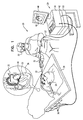
- Fig. 1 is a schematic, pictorial illustration of a catheter tracking system 20, in accordance with an embodiment of the present invention.
- System 20 comprises a probe 22, in the present example a cardiac catheter, and a control console 24.
- catheter 22 may be used for any suitable therapeutic and/or diagnostic purposes, such as ablation of tissue in a heart 26 and the mapping of electro-cardiac signals for the diagnosis of cardiac dysfunctions, such as cardiac arrhythmias, for example.
- Console 24 comprises a processor 42, typically a general-purpose computer, with suitable front end and interface circuits for receiving signals from catheter 22 (such as differential signals as will be described later) and for controlling the other components of system 20 described herein.
- Processor 42 may be programmed in software to carry out the functions that are used by the system, and the processor stores data for the software in a memory 50.
- the software may be downloaded to console 24 in electronic form, over a network, for example, or it may be provided on non-transitory tangible media, such as optical, magnetic or electronic memory media. Alternatively, some or all of the functions of processor 42 may be carried out by dedicated or programmable digital hardware components.
- Operator 30 moves a distal end 40 of catheter 22 in the vicinity of the target region in heart 26 by manipulating catheter 22 with a manipulator 32 near the proximal end of the catheter as shown in the inset of Fig. 1 .
- the proximal end of catheter 22 is connected to interface circuitry in processor 42.
- console 24 comprises a driver circuit 34, which drives magnetic field generators 36 placed at known positions external to patient 28 lying on table 29, e.g., below the patient's torso.
- a magnetic field sensor is installed in catheter 22 near distal end 40 (not shown in Fig. 1 , but will be shown in Fig. 2 below).
- the sensor generates electrical position signals in response to the magnetic fields from the coils, thereby enabling processor 42 to determine the position, (e.g., the location and orientation) of catheter distal end 40 within the heart cavity.
- Cabling within the lumen of catheter 22 connect the magnetic sensor at catheter distal end 40 to interface circuitry in processor 42 at the catheter proximal end.
- Operator 30 can view the position of catheter distal end 40 on an image 44 of heart 26 on a user display 46.
- This method of position sensing is implemented, for example, in the CARTO TM system, produced by Biosense Webster Inc. (Diamond Bar, Calif.) and is described in detail in U.S. Pat. Nos. 5,391,199 , 6,690,963 , 6,484,118 , 6,239,724 , 6,618,612 and 6,332,089 , in PCT Patent Publication WO 96/05768 , and in U.S. Patent Application Publications 2002/0065455 A1 , 2003/0120150 A1 and 2004/0068178 A1 , whose disclosures are all incorporated herein by reference.
- a catheter braid may be disposed along the length of the catheter from the proximal to distal end.
- the catheter braid is typically formed from multiple wires which are woven into the desired braid configuration.
- the braid may be placed in any suitable position within the catheter lumen along the length of the catheter.
- the multiple wires are typically coiled along the length of the elongate member to form the catheter braid.
- the catheter braid wire may be woven into a mesh, spiral coil, or any suitable pattern.
- the terms “braid” and “braid wires” refer to any suitable configuration of the wires, including various meshed and coiled configurations.
- pairs of wires chosen from among the multiple wires forming the catheter braid are used to form electrical interconnects to relay signals between elements near the catheter's distal end to medical equipment at the proximal end.
- Fig. 2 is a diagram schematically illustrating multiple wires 103 in a catheter braid 100 used for signal transmission, in accordance with an embodiment of the present invention.
- operator manipulator 32 is connected to catheter 22 at the catheter proximal end.
- Catheter braid 100 is formed from multiple catheter braid wires 103, typically metal wires, and are shown in the upper portion of Fig. 2 as a metal coil braid.
- Catheter 22 comprises an insertion tube 105 and multiple wires 103 that are coiled around the length of an elongate flexible member 110.
- Elongate flexible member 110 is configured to be inserted into insertion tube 105.
- Two pairs of wires can be seen in Fig. 2 .
- a first wire pair 130 (shown as bold lines) is connected to a single-axis magnetic sensor 115 at distal end 40, and a second wire pair 125 (shown as dotted lines) is connected to a dummy load 120 that is adjacent to sensor 115.
- Dummy load 120 may comprise any suitable combination of resistors, inductors, capacitors, a short, or any suitable electronic element for terminating second wire pair 125.
- Braid 100 is shown as if there are two pairs connected across sensor 115 and dummy load 120, e.g., four wires that coil around elongate member 110 to form braid 100.
- braid 100 may be formed from any suitable number of wires. Any suitable number of wire pairs may be chosen from among the multiple wires in braid 100 to connect to any number of elements at catheter distal end 40 to medical equipment at the catheter proximal end.
- the braid wires used for signal transmission are electrically-insulated from one another and from other braid wires.
- Fig. 2 The catheter structure shown in Fig. 2 is for conceptual clarity and not by way of limitation of the embodiments of the present invention. There are many catheter structures and configurations which can be used depending in the medical procedure as described previously.
- Fig. 2 shows a braid in which the wires are coiled, i.e., wound helically, in alternative embodiments the wires may be braided in any other suitable way, such as in a cross-braiding configuration.
- the disclosed techniques can be used with various other kinds of probes.
- the probe comprises a guide-wire fitted with a magnetic sensor similar to sensor 115 (e.g., a single-axis sensor) and a dummy load similar to dummy load 120.
- catheter 22 comprises an insertion tube 105.
- Braid 100 is coiled around elongate member 110, the elongate member inserted into any suitable position within the lumen of insertion tube 105 and contained in the insertion tube.
- the elongate member may be potted and held rigidly within the insertion tube.
- the catheter may comprise a multilayered insertion tube formed from an outer layer, the braid, and an inner layer forming the inner wall of the catheter lumen.
- elongate member 110 comprises a second flexible tube.
- the second flexible tube is contained within insertion tube 105 and connected to the insertion tube along the length of the insertion tube, thus forming the inner wall of the catheter lumen.
- Braid 100 is sandwiched between insertion tube 102 and the second flexible tube.
- the insertion tube and elongate flexible member are typically formed from polymers, but may be formed from any suitable material by any suitable method, such as extrusion.
- any type of braid pattern of multiple wires 103 may be implemented, such that braid 100 is not limited to a coil as shown in Fig. 2 .
- Wires 103 may be formed from metal or any suitable conducting material to provide mechanical flexibility to the catheter.
- the multiple wires may be insulated.
- the sensor and/or any suitable elements may be connected to the wire through openings formed in the insulation.
- the magnetic sensor at distal end 40 is not limited to a single-axis sensor, but may be any suitable sensor structure.
- the wires that traverse the length of the catheter from connecting electrodes and/or sensors near the distal end to medical equipment at the proximal end are subject to various spurious noise sources.
- the induced differential electrical signal from sensor 115 in response to the magnetic field generated by magnetic sources 36 may be corrupted by different noise sources as the differential signal traverses pair 130 in braid 100.
- inductive pickup from magnetic sources 36 in the unshielded pair 130 can give rise to spurious signals from magnetic sources 36.
- Inductive pickup can also come from an RF generator (e.g., driver circuit 34 that drives field generators 36).
- dummy load 120 is placed next to sensor 115.
- Second pair 125 of wires is connected across dummy load 120.
- the two wire pairs (130 and 125) experience approximately the same noise environment along the length of catheter 22 from the distal to the proximal end of catheter 22.
- any spurious noise pickup induced in second pair 125 with dummy load 120 can be used to remove the spurious noise pickup in the differential signal in the first pair 130, which corrupts the signal from single-axis sensor 115.
- differential amplifier circuitry 135 can be used to measure and amplify the respective signals from sensor 115 and dummy load 120 from first pair 130 and second pair 125, respectively, by any suitable method.
- a first differential amplifier 140 amplifies the differential signal from sensor 115 in first pair 130.
- the single ended signal output of amplifier 140 is denoted S.
- a second differential amplifier 145 amplifies the signal from dummy load 120 in second pair 125.
- the single ended signal output of amplifier 145 is denoted N for the spurious (common-mode) inductive pickup noise coupled into the wires of second pair 125.
- Differential amplifier circuitry 135 may be a separate unit, or it may be integrated within processor unit 42 at the proximal end of catheter 22.
- signal S is the sensor signal corrupted by spurious pickup noise.
- Processor 42 is configured to use the noise N to remove the noise from the sensor signal.
- processor 42 may use the noise N in second pair 125 to remove the noise N from the sensor signal S transmitted along the length of first pair 130 by any suitable digital and/or analog technique, such as subtracting the noise N from the signal S.
- analog subtraction of N from S can be performed internally in circuitry 135. In either case, processor 42 estimates the position coordinates of sensor 115 (and thus of distal end 40) based on the interference-free signal S-N.
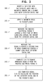
- Fig. 3 is a flow chart that schematically illustrates a method for interference-proof catheter position tracking, in accordance with an embodiment of the present invention.
- catheter 22 is inserted into patient body 28 with magnetic sensor 115 and dummy load 120 near catheter distal end 40.
- a magnetic field is applied to patient body 28 from magnetic sources 36.
- circuitry 135 measures the induced signal S across first wire pair 130 connected across sensor 115 near catheter distal end 40.
- circuitry 135 measures the signal N across second pair 125 connected across dummy load 120 near catheter distal end 40.
- processor 42 computes signal S-N to remove unwanted noise N from the original signal S induced in distal end sensor 115 in response to the applied magnetic field.
- processor 42 uses computed signal S-N to calculate the position of catheter distal end 40 in patient body 28.
- external subsystem refers to any suitable combination of processor 42, differential amplifier circuitry 135, or any other medical equipment circuitry needed to perform the functions of catheter tracking system 20 described herein in accordance with the embodiments of the present invention.
- the embodiments described herein mainly address cardiac catheters
- the methods and systems described herein can also be used in other applications, such as in catheters or location-enabled guide-wires used in other body organs and in other types of intra-body probes.
Applications Claiming Priority (1)
| Application Number | Priority Date | Filing Date | Title |
|---|---|---|---|
| US14/157,739 US9480416B2 (en) | 2014-01-17 | 2014-01-17 | Signal transmission using catheter braid wires |
Publications (2)
| Publication Number | Publication Date |
|---|---|
| EP2896383A1 true EP2896383A1 (de) | 2015-07-22 |
| EP2896383B1 EP2896383B1 (de) | 2020-08-19 |
Family
ID=52434543
Family Applications (1)
| Application Number | Title | Priority Date | Filing Date |
|---|---|---|---|
| EP15151379.3A Active EP2896383B1 (de) | 2014-01-17 | 2015-01-16 | Signalübertragung mit Kathetergeflechtdrähten |
Country Status (7)
| Country | Link |
|---|---|
| US (1) | US9480416B2 (de) |
| EP (1) | EP2896383B1 (de) |
| JP (1) | JP6495016B2 (de) |
| CN (1) | CN104783892B (de) |
| AU (1) | AU2015200138B2 (de) |
| CA (1) | CA2877253A1 (de) |
| IL (1) | IL236165B (de) |
Cited By (3)
| Publication number | Priority date | Publication date | Assignee | Title |
|---|---|---|---|---|
| EP3389541A4 (de) * | 2016-02-03 | 2019-11-27 | St. Jude Medical International Holding S.à r.l. | System und verfahren zur unterdrückung von quellinduzierten fehlern |
| EP3586737A1 (de) * | 2018-06-29 | 2020-01-01 | Biosense Webster (Israel) Ltd. | Referenzdrähte zur beseitigung von rauschen und artefakten in mapping-herzkatheter |
| US11229402B2 (en) | 2015-05-29 | 2022-01-25 | Microvention, Inc. | Catheter circuit |
Families Citing this family (36)
| Publication number | Priority date | Publication date | Assignee | Title |
|---|---|---|---|---|
| US20170354338A1 (en) * | 2016-06-09 | 2017-12-14 | Biosense Webster (Israel) Ltd. | Dual-function sensors for a basket catheter |
| EP3568168B1 (de) * | 2017-01-12 | 2023-11-22 | Medtronic Inc. | Schlauchhülle für eine implantierbare vorrichtung |
| JP6256962B1 (ja) | 2017-06-21 | 2018-01-10 | 朝日インテック株式会社 | 磁気式の方位・位置測定装置 |
| JP7262886B2 (ja) | 2017-07-21 | 2023-04-24 | 朝日インテック株式会社 | 超小型高感度磁気センサ |
| TWI712432B (zh) * | 2018-03-05 | 2020-12-11 | 鄭惇方 | 生物能量訊號擷取及轉換裝置 |
| US20200038101A1 (en) | 2018-08-03 | 2020-02-06 | Biosense Webster (Israel) Ltd. | Unipolar reference electrode for electrophysiology mapping catheter |
| WO2020104888A1 (en) | 2018-11-21 | 2020-05-28 | Biosense Webster (Israel) Ltd. | Ablation catheter with stacked circuit assembly |
| US20200297281A1 (en) | 2019-03-18 | 2020-09-24 | Biosense Webster (Israel) Ltd. | Electrode configurations for diagnosis of arrhythmias |
| US10736207B1 (en) * | 2019-04-03 | 2020-08-04 | Biosense Webster (Israel) Ltd. | Canceling magnetic pickup using three-dimensional wiring assembly |
| US11744480B2 (en) | 2019-06-25 | 2023-09-05 | Biosense Webster (Israel) Ltd. | Catheter deflection system with deflection load limiter |
| US20200405385A1 (en) | 2019-06-25 | 2020-12-31 | Biosense Webster (Israel) Ltd. | Irrigation fluid monitor and alarm |
| US11540878B2 (en) | 2019-07-17 | 2023-01-03 | Biosense Webster (Israel) Ltd. | Blooming leaflet catheter with high density electrode array |
| US20210059744A1 (en) | 2019-09-03 | 2021-03-04 | Biosense Webster (Israel) Ltd. | Catheter construction to eliminate static and noise |
| US20210059745A1 (en) | 2019-09-03 | 2021-03-04 | Biosense Webster (Israel) Ltd. | Mapping catheter with flex panel electrode assembly |
| US20210077184A1 (en) | 2019-09-16 | 2021-03-18 | Biosense Webster (Israel) Ltd. | Catheter with thin-film electrodes on expandable membrane |
| US11896395B2 (en) | 2019-09-17 | 2024-02-13 | Biosense Webster (Israel) Ltd. | Catheter with insert-molded microelectrode |
| US20210077183A1 (en) | 2019-09-18 | 2021-03-18 | Biosense Webster (Israel) Ltd. | Catheter with thin-film electrodes on expandable mechanical structure |
| US20210085386A1 (en) | 2019-09-20 | 2021-03-25 | Biosense Webster (Israel) Ltd. | Catheter instrument with three pull wires |
| US20210113812A1 (en) | 2019-10-22 | 2021-04-22 | Biosense Webster (Israel) Ltd. | Flared insert member for use with catheter assembly |
| US20210121231A1 (en) | 2019-10-23 | 2021-04-29 | Biosense Webster (Israel) Ltd. | Cardiac mapping catheter with square-spaced electrodes |
| US11918751B2 (en) | 2019-11-12 | 2024-03-05 | Biosense Webster (Israel) Ltd. | Catheter with vapor deposited features on tip |
| CN110870791B (zh) * | 2019-12-04 | 2021-09-03 | 上海微创电生理医疗科技股份有限公司 | 医用介入式针组件与医用介入式导管 |
| US20210177506A1 (en) | 2019-12-16 | 2021-06-17 | Biosense Webster (Israel) Ltd. | Catheter deflection control assembly |
| US20210220042A1 (en) | 2020-01-17 | 2021-07-22 | Biosense Webster (Israel) Ltd. | Catheter with integrated thin-film microsensors |
| US11857267B2 (en) * | 2020-04-22 | 2024-01-02 | Medtronic Navigation, Inc. | System and method for navigation |
| JP2021186647A (ja) | 2020-05-29 | 2021-12-13 | バイオセンス・ウエブスター・(イスラエル)・リミテッドBiosense Webster (Israel), Ltd. | 不整脈を診断するための電極装置 |
| CN112221006A (zh) * | 2020-10-19 | 2021-01-15 | 湖北工业大学 | 一种用于快速诊断急性肺栓塞的导管介入电磁导引装置 |
| US20220202370A1 (en) * | 2020-12-29 | 2022-06-30 | Biosense Webster (Israel) Ltd. | Systems, methods, and processes for detecting electrode wire noise |
| US20230149069A1 (en) | 2021-11-16 | 2023-05-18 | Biosense Webster (Israel) Ltd. | Planar catheter with overlapping electrode pairs |
| US20230181241A1 (en) | 2021-12-10 | 2023-06-15 | Biosense Webster (Israel) Ltd. | Electrical paths along flexible section of deflectable sheath |
| US20230190367A1 (en) | 2021-12-17 | 2023-06-22 | Biosense Webster (Israel) Ltd. | Catheter end effector with laterally projecting body |
| US20230200895A1 (en) | 2021-12-27 | 2023-06-29 | Biosense Webster (Israel) Ltd. | Catheter end effector with resilient frame and flexible interior |
| US20230310071A1 (en) | 2022-04-05 | 2023-10-05 | Biosense Webster (Israel) Ltd. | Catheter with external magnetic coils |
| US20240091502A1 (en) | 2022-09-20 | 2024-03-21 | Biosense Webster (Israel) Ltd. | Catheter shaft with multi-plane articulation and rotation |
| US20240099768A1 (en) | 2022-09-22 | 2024-03-28 | Biosense Webster (Israel) Ltd. | Two-segment deflectin catheter with side exit guidwire lumen |
| US20240123210A1 (en) | 2022-10-18 | 2024-04-18 | Biosense Webster (Israel) Ltd. | Catheter insertion tool |
Citations (14)
| Publication number | Priority date | Publication date | Assignee | Title |
|---|---|---|---|---|
| US5391199A (en) | 1993-07-20 | 1995-02-21 | Biosense, Inc. | Apparatus and method for treating cardiac arrhythmias |
| WO1996005768A1 (en) | 1994-08-19 | 1996-02-29 | Biosense, Inc. | Medical diagnosis, treatment and imaging systems |
| US6213995B1 (en) * | 1999-08-31 | 2001-04-10 | Phelps Dodge High Performance Conductors Of Sc And Ga, Inc. | Flexible tubing with braided signal transmission elements |
| US6239724B1 (en) | 1997-12-30 | 2001-05-29 | Remon Medical Technologies, Ltd. | System and method for telemetrically providing intrabody spatial position |
| US6332089B1 (en) | 1996-02-15 | 2001-12-18 | Biosense, Inc. | Medical procedures and apparatus using intrabody probes |
| US20020065455A1 (en) | 1995-01-24 | 2002-05-30 | Shlomo Ben-Haim | Medical diagnosis, treatment and imaging systems |
| US6484118B1 (en) | 2000-07-20 | 2002-11-19 | Biosense, Inc. | Electromagnetic position single axis system |
| US20030120150A1 (en) | 2001-12-21 | 2003-06-26 | Assaf Govari | Wireless position sensor |
| US6618612B1 (en) | 1996-02-15 | 2003-09-09 | Biosense, Inc. | Independently positionable transducers for location system |
| US20040068178A1 (en) | 2002-09-17 | 2004-04-08 | Assaf Govari | High-gradient recursive locating system |
| US7881769B2 (en) | 2002-11-18 | 2011-02-01 | Mediguide Ltd. | Method and system for mounting an MPS sensor on a catheter |
| US20110066029A1 (en) * | 2009-09-11 | 2011-03-17 | Medtronic, Inc. | Electromagnetic Medical Device |
| US20110156700A1 (en) * | 2009-12-31 | 2011-06-30 | Itay Kariv | System and method for assessing interference to a signal caused by a magnetic field |
| US20120182014A1 (en) | 2009-08-12 | 2012-07-19 | Debra Strick Rivera | Magnetic resonance microcoil and method of use |
Family Cites Families (10)
| Publication number | Priority date | Publication date | Assignee | Title |
|---|---|---|---|---|
| DE69736826T2 (de) | 1996-12-05 | 2007-05-16 | Philips Medical Systems (Cleveland), Inc., Cleveland | Radiofrequenzspulen für Kernresonanz |
| US6374667B1 (en) * | 1998-10-30 | 2002-04-23 | Volusense As | Volumetric physiological measuring system and method |
| US6408199B1 (en) * | 2000-07-07 | 2002-06-18 | Biosense, Inc. | Bipolar mapping of intracardiac potentials with electrode having blood permeable covering |
| DE60230499D1 (de) * | 2001-04-27 | 2009-02-05 | Bard Inc C R | Katheter zur drei-dimensionallen abbildung der elektrischen aktivität in blutgefässen |
| JP4827495B2 (ja) * | 2005-11-09 | 2011-11-30 | Hoya株式会社 | 内視鏡挿入部形状把握システム |
| IL196660A (en) * | 2008-01-23 | 2014-09-30 | Mediguide Ltd | Flexible conductive catheter with sensor |
| US8926528B2 (en) * | 2008-08-06 | 2015-01-06 | Biosense Webster, Inc. | Single-axis sensors on flexible backbone |
| CN101836862B (zh) * | 2009-03-16 | 2014-03-26 | 上海微创医疗器械(集团)有限公司 | 人体腔室内壁三维标测方法及其设备和系统 |
| US9211094B2 (en) * | 2010-12-10 | 2015-12-15 | Biosense Webster (Israel), Ltd. | System and method for detection of metal disturbance based on contact force measurement |
| US8636718B2 (en) * | 2010-12-30 | 2014-01-28 | St. Jude Medical, Atrial Fibrillation Division, Inc. | Method of assembling a positioning sensor and associated wiring on a medical tool |
-
2014
- 2014-01-17 US US14/157,739 patent/US9480416B2/en active Active
- 2014-12-10 IL IL236165A patent/IL236165B/en active IP Right Grant
-
2015
- 2015-01-09 CA CA2877253A patent/CA2877253A1/en not_active Abandoned
- 2015-01-13 AU AU2015200138A patent/AU2015200138B2/en not_active Ceased
- 2015-01-16 CN CN201510024041.9A patent/CN104783892B/zh active Active
- 2015-01-16 EP EP15151379.3A patent/EP2896383B1/de active Active
- 2015-01-16 JP JP2015006484A patent/JP6495016B2/ja active Active
Patent Citations (15)
| Publication number | Priority date | Publication date | Assignee | Title |
|---|---|---|---|---|
| US5391199A (en) | 1993-07-20 | 1995-02-21 | Biosense, Inc. | Apparatus and method for treating cardiac arrhythmias |
| WO1996005768A1 (en) | 1994-08-19 | 1996-02-29 | Biosense, Inc. | Medical diagnosis, treatment and imaging systems |
| US6690963B2 (en) | 1995-01-24 | 2004-02-10 | Biosense, Inc. | System for determining the location and orientation of an invasive medical instrument |
| US20020065455A1 (en) | 1995-01-24 | 2002-05-30 | Shlomo Ben-Haim | Medical diagnosis, treatment and imaging systems |
| US6618612B1 (en) | 1996-02-15 | 2003-09-09 | Biosense, Inc. | Independently positionable transducers for location system |
| US6332089B1 (en) | 1996-02-15 | 2001-12-18 | Biosense, Inc. | Medical procedures and apparatus using intrabody probes |
| US6239724B1 (en) | 1997-12-30 | 2001-05-29 | Remon Medical Technologies, Ltd. | System and method for telemetrically providing intrabody spatial position |
| US6213995B1 (en) * | 1999-08-31 | 2001-04-10 | Phelps Dodge High Performance Conductors Of Sc And Ga, Inc. | Flexible tubing with braided signal transmission elements |
| US6484118B1 (en) | 2000-07-20 | 2002-11-19 | Biosense, Inc. | Electromagnetic position single axis system |
| US20030120150A1 (en) | 2001-12-21 | 2003-06-26 | Assaf Govari | Wireless position sensor |
| US20040068178A1 (en) | 2002-09-17 | 2004-04-08 | Assaf Govari | High-gradient recursive locating system |
| US7881769B2 (en) | 2002-11-18 | 2011-02-01 | Mediguide Ltd. | Method and system for mounting an MPS sensor on a catheter |
| US20120182014A1 (en) | 2009-08-12 | 2012-07-19 | Debra Strick Rivera | Magnetic resonance microcoil and method of use |
| US20110066029A1 (en) * | 2009-09-11 | 2011-03-17 | Medtronic, Inc. | Electromagnetic Medical Device |
| US20110156700A1 (en) * | 2009-12-31 | 2011-06-30 | Itay Kariv | System and method for assessing interference to a signal caused by a magnetic field |
Cited By (5)
| Publication number | Priority date | Publication date | Assignee | Title |
|---|---|---|---|---|
| US11229402B2 (en) | 2015-05-29 | 2022-01-25 | Microvention, Inc. | Catheter circuit |
| EP3389541A4 (de) * | 2016-02-03 | 2019-11-27 | St. Jude Medical International Holding S.à r.l. | System und verfahren zur unterdrückung von quellinduzierten fehlern |
| US11045110B2 (en) | 2016-02-03 | 2021-06-29 | St. Jude Medical International Holding S.À R.L. | System and method of cancellation of source induced errors |
| EP3586737A1 (de) * | 2018-06-29 | 2020-01-01 | Biosense Webster (Israel) Ltd. | Referenzdrähte zur beseitigung von rauschen und artefakten in mapping-herzkatheter |
| US11779280B2 (en) | 2018-06-29 | 2023-10-10 | Biosense Webster (Israel) Ltd. | Reference wires to remove noise and artifacts in cardiac mapping catheter |
Also Published As
| Publication number | Publication date |
|---|---|
| JP2015134166A (ja) | 2015-07-27 |
| IL236165B (en) | 2018-01-31 |
| AU2015200138A1 (en) | 2015-08-06 |
| US9480416B2 (en) | 2016-11-01 |
| US20150201864A1 (en) | 2015-07-23 |
| JP6495016B2 (ja) | 2019-04-03 |
| CA2877253A1 (en) | 2015-07-17 |
| CN104783892A (zh) | 2015-07-22 |
| AU2015200138B2 (en) | 2019-01-31 |
| CN104783892B (zh) | 2018-10-16 |
| EP2896383B1 (de) | 2020-08-19 |
Similar Documents
| Publication | Publication Date | Title |
|---|---|---|
| US9480416B2 (en) | Signal transmission using catheter braid wires | |
| EP2915498B1 (de) | Mehrarmiger katheter mit signalübertragung über geflechtdrähte | |
| EP3858233B1 (de) | Auf eine gefaltete flexible leiterplatte gedruckte, multiaxiale positionssensoren | |
| US10105073B2 (en) | Flexible multiple-arm diagnostic catheter | |
| JP5762836B2 (ja) | 位置依存性干渉の相殺 | |
| EP2897524B1 (de) | Kointegrationsfilter für ein katheternavigationssystem | |
| CA2920863A1 (en) | Angioplasty guidewire | |
| CN111511303A (zh) | 导管和用于导管组装的方法 | |
| US11744479B2 (en) | Multi-layer flat coil magnetic transmitters | |
| US9423475B2 (en) | Electrical lead assemblies for MRI-compatible medical devices and MRI-compatible medical devices incorporating same | |
| CN104042206B (zh) | 具有形状记忆的保护锁 |
Legal Events
| Date | Code | Title | Description |
|---|---|---|---|
| PUAI | Public reference made under article 153(3) epc to a published international application that has entered the european phase |
Free format text: ORIGINAL CODE: 0009012 |
|
| 17P | Request for examination filed |
Effective date: 20150116 |
|
| AK | Designated contracting states |
Kind code of ref document: A1 Designated state(s): AL AT BE BG CH CY CZ DE DK EE ES FI FR GB GR HR HU IE IS IT LI LT LU LV MC MK MT NL NO PL PT RO RS SE SI SK SM TR |
|
| AX | Request for extension of the european patent |
Extension state: BA ME |
|
| 17P | Request for examination filed |
Effective date: 20151216 |
|
| RBV | Designated contracting states (corrected) |
Designated state(s): AL AT BE BG CH CY CZ DE DK EE ES FI FR GB GR HR HU IE IS IT LI LT LU LV MC MK MT NL NO PL PT RO RS SE SI SK SM TR |
|
| STAA | Information on the status of an ep patent application or granted ep patent |
Free format text: STATUS: EXAMINATION IS IN PROGRESS |
|
| 17Q | First examination report despatched |
Effective date: 20171204 |
|
| REG | Reference to a national code |
Ref country code: DE Ref legal event code: R079 Ref document number: 602015057586 Country of ref document: DE Free format text: PREVIOUS MAIN CLASS: A61B0019000000 Ipc: A61B0034200000 |
|
| GRAP | Despatch of communication of intention to grant a patent |
Free format text: ORIGINAL CODE: EPIDOSNIGR1 |
|
| STAA | Information on the status of an ep patent application or granted ep patent |
Free format text: STATUS: GRANT OF PATENT IS INTENDED |
|
| RIC1 | Information provided on ipc code assigned before grant |
Ipc: A61M 25/01 20060101ALI20200511BHEP Ipc: A61B 34/20 20160101AFI20200511BHEP Ipc: A61M 25/00 20060101ALI20200511BHEP |
|
| INTG | Intention to grant announced |
Effective date: 20200608 |
|
| GRAS | Grant fee paid |
Free format text: ORIGINAL CODE: EPIDOSNIGR3 |
|
| GRAA | (expected) grant |
Free format text: ORIGINAL CODE: 0009210 |
|
| STAA | Information on the status of an ep patent application or granted ep patent |
Free format text: STATUS: THE PATENT HAS BEEN GRANTED |
|
| AK | Designated contracting states |
Kind code of ref document: B1 Designated state(s): AL AT BE BG CH CY CZ DE DK EE ES FI FR GB GR HR HU IE IS IT LI LT LU LV MC MK MT NL NO PL PT RO RS SE SI SK SM TR |
|
| RAP1 | Party data changed (applicant data changed or rights of an application transferred) |
Owner name: BIOSENSE WEBSTER (ISRAEL) LTD. |
|
| REG | Reference to a national code |
Ref country code: CH Ref legal event code: EP |
|
| REG | Reference to a national code |
Ref country code: DE Ref legal event code: R096 Ref document number: 602015057586 Country of ref document: DE |
|
| REG | Reference to a national code |
Ref country code: AT Ref legal event code: REF Ref document number: 1303066 Country of ref document: AT Kind code of ref document: T Effective date: 20200915 |
|
| REG | Reference to a national code |
Ref country code: IE Ref legal event code: FG4D |
|
| REG | Reference to a national code |
Ref country code: NL Ref legal event code: FP |
|
| REG | Reference to a national code |
Ref country code: LT Ref legal event code: MG4D |
|
| PG25 | Lapsed in a contracting state [announced via postgrant information from national office to epo] |
Ref country code: SE Free format text: LAPSE BECAUSE OF FAILURE TO SUBMIT A TRANSLATION OF THE DESCRIPTION OR TO PAY THE FEE WITHIN THE PRESCRIBED TIME-LIMIT Effective date: 20200819 Ref country code: FI Free format text: LAPSE BECAUSE OF FAILURE TO SUBMIT A TRANSLATION OF THE DESCRIPTION OR TO PAY THE FEE WITHIN THE PRESCRIBED TIME-LIMIT Effective date: 20200819 Ref country code: BG Free format text: LAPSE BECAUSE OF FAILURE TO SUBMIT A TRANSLATION OF THE DESCRIPTION OR TO PAY THE FEE WITHIN THE PRESCRIBED TIME-LIMIT Effective date: 20201119 Ref country code: NO Free format text: LAPSE BECAUSE OF FAILURE TO SUBMIT A TRANSLATION OF THE DESCRIPTION OR TO PAY THE FEE WITHIN THE PRESCRIBED TIME-LIMIT Effective date: 20201119 Ref country code: GR Free format text: LAPSE BECAUSE OF FAILURE TO SUBMIT A TRANSLATION OF THE DESCRIPTION OR TO PAY THE FEE WITHIN THE PRESCRIBED TIME-LIMIT Effective date: 20201120 Ref country code: PT Free format text: LAPSE BECAUSE OF FAILURE TO SUBMIT A TRANSLATION OF THE DESCRIPTION OR TO PAY THE FEE WITHIN THE PRESCRIBED TIME-LIMIT Effective date: 20201221 Ref country code: HR Free format text: LAPSE BECAUSE OF FAILURE TO SUBMIT A TRANSLATION OF THE DESCRIPTION OR TO PAY THE FEE WITHIN THE PRESCRIBED TIME-LIMIT Effective date: 20200819 Ref country code: LT Free format text: LAPSE BECAUSE OF FAILURE TO SUBMIT A TRANSLATION OF THE DESCRIPTION OR TO PAY THE FEE WITHIN THE PRESCRIBED TIME-LIMIT Effective date: 20200819 |
|
| REG | Reference to a national code |
Ref country code: AT Ref legal event code: MK05 Ref document number: 1303066 Country of ref document: AT Kind code of ref document: T Effective date: 20200819 |
|
| PG25 | Lapsed in a contracting state [announced via postgrant information from national office to epo] |
Ref country code: IS Free format text: LAPSE BECAUSE OF FAILURE TO SUBMIT A TRANSLATION OF THE DESCRIPTION OR TO PAY THE FEE WITHIN THE PRESCRIBED TIME-LIMIT Effective date: 20201219 Ref country code: LV Free format text: LAPSE BECAUSE OF FAILURE TO SUBMIT A TRANSLATION OF THE DESCRIPTION OR TO PAY THE FEE WITHIN THE PRESCRIBED TIME-LIMIT Effective date: 20200819 Ref country code: PL Free format text: LAPSE BECAUSE OF FAILURE TO SUBMIT A TRANSLATION OF THE DESCRIPTION OR TO PAY THE FEE WITHIN THE PRESCRIBED TIME-LIMIT Effective date: 20200819 Ref country code: RS Free format text: LAPSE BECAUSE OF FAILURE TO SUBMIT A TRANSLATION OF THE DESCRIPTION OR TO PAY THE FEE WITHIN THE PRESCRIBED TIME-LIMIT Effective date: 20200819 |
|
| PG25 | Lapsed in a contracting state [announced via postgrant information from national office to epo] |
Ref country code: CZ Free format text: LAPSE BECAUSE OF FAILURE TO SUBMIT A TRANSLATION OF THE DESCRIPTION OR TO PAY THE FEE WITHIN THE PRESCRIBED TIME-LIMIT Effective date: 20200819 Ref country code: DK Free format text: LAPSE BECAUSE OF FAILURE TO SUBMIT A TRANSLATION OF THE DESCRIPTION OR TO PAY THE FEE WITHIN THE PRESCRIBED TIME-LIMIT Effective date: 20200819 Ref country code: RO Free format text: LAPSE BECAUSE OF FAILURE TO SUBMIT A TRANSLATION OF THE DESCRIPTION OR TO PAY THE FEE WITHIN THE PRESCRIBED TIME-LIMIT Effective date: 20200819 Ref country code: SM Free format text: LAPSE BECAUSE OF FAILURE TO SUBMIT A TRANSLATION OF THE DESCRIPTION OR TO PAY THE FEE WITHIN THE PRESCRIBED TIME-LIMIT Effective date: 20200819 Ref country code: EE Free format text: LAPSE BECAUSE OF FAILURE TO SUBMIT A TRANSLATION OF THE DESCRIPTION OR TO PAY THE FEE WITHIN THE PRESCRIBED TIME-LIMIT Effective date: 20200819 |
|
| REG | Reference to a national code |
Ref country code: DE Ref legal event code: R097 Ref document number: 602015057586 Country of ref document: DE |
|
| PG25 | Lapsed in a contracting state [announced via postgrant information from national office to epo] |
Ref country code: ES Free format text: LAPSE BECAUSE OF FAILURE TO SUBMIT A TRANSLATION OF THE DESCRIPTION OR TO PAY THE FEE WITHIN THE PRESCRIBED TIME-LIMIT Effective date: 20200819 Ref country code: AL Free format text: LAPSE BECAUSE OF FAILURE TO SUBMIT A TRANSLATION OF THE DESCRIPTION OR TO PAY THE FEE WITHIN THE PRESCRIBED TIME-LIMIT Effective date: 20200819 Ref country code: AT Free format text: LAPSE BECAUSE OF FAILURE TO SUBMIT A TRANSLATION OF THE DESCRIPTION OR TO PAY THE FEE WITHIN THE PRESCRIBED TIME-LIMIT Effective date: 20200819 |
|
| PLBE | No opposition filed within time limit |
Free format text: ORIGINAL CODE: 0009261 |
|
| STAA | Information on the status of an ep patent application or granted ep patent |
Free format text: STATUS: NO OPPOSITION FILED WITHIN TIME LIMIT |
|
| PG25 | Lapsed in a contracting state [announced via postgrant information from national office to epo] |
Ref country code: SK Free format text: LAPSE BECAUSE OF FAILURE TO SUBMIT A TRANSLATION OF THE DESCRIPTION OR TO PAY THE FEE WITHIN THE PRESCRIBED TIME-LIMIT Effective date: 20200819 |
|
| 26N | No opposition filed |
Effective date: 20210520 |
|
| PG25 | Lapsed in a contracting state [announced via postgrant information from national office to epo] |
Ref country code: SI Free format text: LAPSE BECAUSE OF FAILURE TO SUBMIT A TRANSLATION OF THE DESCRIPTION OR TO PAY THE FEE WITHIN THE PRESCRIBED TIME-LIMIT Effective date: 20200819 Ref country code: MC Free format text: LAPSE BECAUSE OF FAILURE TO SUBMIT A TRANSLATION OF THE DESCRIPTION OR TO PAY THE FEE WITHIN THE PRESCRIBED TIME-LIMIT Effective date: 20200819 |
|
| REG | Reference to a national code |
Ref country code: CH Ref legal event code: PL |
|
| PG25 | Lapsed in a contracting state [announced via postgrant information from national office to epo] |
Ref country code: LU Free format text: LAPSE BECAUSE OF NON-PAYMENT OF DUE FEES Effective date: 20210116 |
|
| REG | Reference to a national code |
Ref country code: BE Ref legal event code: MM Effective date: 20210131 |
|
| PG25 | Lapsed in a contracting state [announced via postgrant information from national office to epo] |
Ref country code: LI Free format text: LAPSE BECAUSE OF NON-PAYMENT OF DUE FEES Effective date: 20210131 Ref country code: CH Free format text: LAPSE BECAUSE OF NON-PAYMENT OF DUE FEES Effective date: 20210131 |
|
| PG25 | Lapsed in a contracting state [announced via postgrant information from national office to epo] |
Ref country code: IE Free format text: LAPSE BECAUSE OF NON-PAYMENT OF DUE FEES Effective date: 20210116 |
|
| PGFP | Annual fee paid to national office [announced via postgrant information from national office to epo] |
Ref country code: NL Payment date: 20211216 Year of fee payment: 8 |
|
| PG25 | Lapsed in a contracting state [announced via postgrant information from national office to epo] |
Ref country code: BE Free format text: LAPSE BECAUSE OF NON-PAYMENT OF DUE FEES Effective date: 20210131 |
|
| PG25 | Lapsed in a contracting state [announced via postgrant information from national office to epo] |
Ref country code: HU Free format text: LAPSE BECAUSE OF FAILURE TO SUBMIT A TRANSLATION OF THE DESCRIPTION OR TO PAY THE FEE WITHIN THE PRESCRIBED TIME-LIMIT; INVALID AB INITIO Effective date: 20150116 |
|
| PGFP | Annual fee paid to national office [announced via postgrant information from national office to epo] |
Ref country code: IT Payment date: 20221213 Year of fee payment: 9 Ref country code: DE Payment date: 20221130 Year of fee payment: 9 |
|
| PG25 | Lapsed in a contracting state [announced via postgrant information from national office to epo] |
Ref country code: CY Free format text: LAPSE BECAUSE OF FAILURE TO SUBMIT A TRANSLATION OF THE DESCRIPTION OR TO PAY THE FEE WITHIN THE PRESCRIBED TIME-LIMIT Effective date: 20200819 |
|
| REG | Reference to a national code |
Ref country code: NL Ref legal event code: MM Effective date: 20230201 |
|
| PG25 | Lapsed in a contracting state [announced via postgrant information from national office to epo] |
Ref country code: NL Free format text: LAPSE BECAUSE OF NON-PAYMENT OF DUE FEES Effective date: 20230201 |
|
| PGFP | Annual fee paid to national office [announced via postgrant information from national office to epo] |
Ref country code: GB Payment date: 20231130 Year of fee payment: 10 |
|
| PGFP | Annual fee paid to national office [announced via postgrant information from national office to epo] |
Ref country code: FR Payment date: 20231212 Year of fee payment: 10 |