EP2896370B1 - Ultraschalldiagnosevorrichtung und ultraschallsonde - Google Patents
Ultraschalldiagnosevorrichtung und ultraschallsonde Download PDFInfo
- Publication number
- EP2896370B1 EP2896370B1 EP13846873.1A EP13846873A EP2896370B1 EP 2896370 B1 EP2896370 B1 EP 2896370B1 EP 13846873 A EP13846873 A EP 13846873A EP 2896370 B1 EP2896370 B1 EP 2896370B1
- Authority
- EP
- European Patent Office
- Prior art keywords
- temperature
- ultrasonic
- diagnosis apparatus
- unit
- ultrasonic probe
- Prior art date
- Legal status (The legal status is an assumption and is not a legal conclusion. Google has not performed a legal analysis and makes no representation as to the accuracy of the status listed.)
- Active
Links
Images




Classifications
-
- A—HUMAN NECESSITIES
- A61—MEDICAL OR VETERINARY SCIENCE; HYGIENE
- A61B—DIAGNOSIS; SURGERY; IDENTIFICATION
- A61B8/00—Diagnosis using ultrasonic, sonic or infrasonic waves
- A61B8/54—Control of the diagnostic device
- A61B8/546—Control of the diagnostic device involving monitoring or regulation of device temperature
-
- A—HUMAN NECESSITIES
- A61—MEDICAL OR VETERINARY SCIENCE; HYGIENE
- A61B—DIAGNOSIS; SURGERY; IDENTIFICATION
- A61B8/00—Diagnosis using ultrasonic, sonic or infrasonic waves
- A61B8/06—Measuring blood flow
-
- A—HUMAN NECESSITIES
- A61—MEDICAL OR VETERINARY SCIENCE; HYGIENE
- A61B—DIAGNOSIS; SURGERY; IDENTIFICATION
- A61B8/00—Diagnosis using ultrasonic, sonic or infrasonic waves
- A61B8/48—Diagnostic techniques
- A61B8/488—Diagnostic techniques involving Doppler signals
Definitions
- Embodiments described herein relate to an ultrasonic diagnosis apparatus and an ultrasonic probe.
- the ultrasonic diagnosis apparatus In an ultrasonic diagnosis apparatus, the temperature of a surface of an ultrasonic probe that contacts a subject sometimes increases. For this reason, the ultrasonic diagnosis apparatus incorporates a temperature sensor in an acoustic module of the ultrasonic probe, and the temperature of a contact surface with the subject is monitored. When the ultrasonic diagnosis apparatus detects an abnormal increase in the temperature of the contact surface, the ultrasonic diagnosis apparatus keeps driving conditions low or stops the operation at the time of an excessive temperature increase, thereby maintaining safety of the subject.
- a plurality of temperature sensors are incorporated in an acoustic module.
- the probe cable becomes large and heavy.
- WO 2008/146208 A2 relates to a wireless ultrasound probe with energy conservation.
- WO 2007/000680 A2 relates to optimized temperature measurement in an ultrasound transducer.
- the present invention has been achieved in view of the above problems, and an object of the invention is to provide an ultrasonic diagnosis apparatus that can maintain the operability of an ultrasonic probe even when the number of temperature sensors is increased, and an ultrasonic probe.
- the present invention has been achieved in view of the above problems, and an object of the invention is to provide an ultrasonic diagnosis apparatus that can maintain the operability of an ultrasonic probe even when the number of temperature sensors is increased, and an ultrasonic probe.
- An ultrasonic diagnosis apparatus includes an ultrasonic probe, an image generation unit, a display unit, and a control unit.
- the ultrasonic probe transmits and receives an ultrasonic wave to and from a subject.
- the image generation unit generates image data from a reflected wave received from the ultrasonic probe.
- the display unit displays the image data.
- the control unit controls transmission and reception of ultrasonic waves by the ultrasonic probe.
- the ultrasonic probe includes a plurality of temperature sensors that measure the temperature of the ultrasonic probe and a switching circuit that is connected to the respective temperature sensors and switches connection to any one of the temperature sensors to a valid state to output data from the temperature sensors to a temperature detector.
- the control unit includes an instruction unit that instructs the switching circuit to switch connection to any one of the temperature sensors to a valid state at a predetermined time interval and a determination unit that determines whether the temperature measured by the temperature detector is within a set temperature range.
- FIG. 1 is an example of a configuration of an ultrasonic diagnosis apparatus 1 according to a first embodiment.
- the ultrasonic diagnosis apparatus 1 according to the first embodiment includes an ultrasonic-diagnosis-apparatus main unit 10 and an ultrasonic probe 50.
- the ultrasonic-diagnosis-apparatus main unit 10 is connected via a connection unit 2 and a probe cable 3 to the ultrasonic probe 50.
- the ultrasonic-diagnosis-apparatus main unit 10 includes a receiving/scanning circuit 21, an image generation unit 22, a display unit 25, a temperature detector 30, and a control unit 40.
- the receiving/scanning circuit 21 receives a signal having a delay added thereto in a reception circuit 80 included in the ultrasonic probe 50 that is explained later via the probe cable 3.
- the receiving/scanning circuit 21 further performs processes such as signal amplitude adjustment and delay addition on the received signal.
- the receiving/scanning circuit 21 then outputs the processed signal to the image generation unit 22.
- the image generation unit 22 includes a blood-flow information detector 22a, an amplitude detector 22b, and a display process unit 22c.
- An output of the receiving/scanning circuit 21 is supplied to the blood-flow information detector 22a together with a reference clock.
- the blood-flow information detector 22a supplies an average speed (or the maximum speed), a speed distribution (or a speed distribution width), and scattering power information from a blood flow to the display process unit 22c. That is, the blood-flow information detector 22a outputs Doppler image information to the display process unit 22c.
- An output of the receiving/scanning circuit 21 is supplied to the amplitude detector 22b.
- the amplitude detector 22b detects the magnitude of a reflected wave of an ultrasonic beam in each raster direction.
- the amplitude detector 22b outputs brightness information of each raster, that is, B-mode image (cross-sectional image) information to the display process unit 22c.
- the display process unit 22c generates display image data from image information.
- the display process unit 22c performs a process of converting a raster direction (a scanning direction) of image data input from the blood-flow information detector 22a and the amplitude detector 22b, and outputs the processed image data to the display unit 25.
- the display unit 25 displays image data generated by the image generation unit 22.
- the temperature detector 30 measures the temperature based on a signal output from a switching circuit 59 that is explained later. For example, the temperature detector 30 measures a resistance value using a signal output from the switching circuit 59 and then measures the temperature using the resistance value. The temperature detector 30 outputs the measured temperature to the control unit 40. Alternatively, a resistance value measured by the temperature detector 30 can be output to the control unit 40 and the control unit 40 can calculate the temperature using the resistance value measured by the temperature detector 30.
- the control unit 40 is a control processor (CPU: Central Processing Unit) that realizes functions as an information processing device, and controls the entire processing of the ultrasonic diagnosis apparatus 1. For example, the control unit 40 controls transmission and reception of ultrasonic waves by the ultrasonic probe 50.
- CPU Central Processing Unit
- control unit 40 includes an instruction unit 41, a determination unit 42, and a changing unit 43, and monitors the temperature detected by the temperature detector 30.
- the control unit 40 is configured so as to be able to cause hardware to forcibly stop operations depending on the degree of an abnormality. Details of the instruction unit 41, the determination unit 42, and the changing unit 43 included in the control unit 40 are explained later with reference to FIG. 4 .
- the ultrasonic probe 50 is an electronic-scanning ultrasonic probe, and includes an acoustic module 51, temperature sensors 53 to 56, a sensor line 57, a reference sensor 58, the switching circuit 59, and an electronic circuit 60.
- the acoustic module 51 is constituted by a large number of ultrasonic transducer elements that are one- or two-dimensionally arrayed. Depending on the type of the ultrasonic probe 50, the ultrasonic transducer elements are linearly arrayed or arrayed in a shape having curvature. By changing a timing of a voltage applied to each transducer element, an ultrasonic beam can be electronically scanned in a fan shape or can be focused. Further, by moving the range of used elements, the position where an ultrasonic beam is generated can be moved.
- the temperature sensors 53 to 55 that detect the temperature of a contact surface with a subject are embedded in the acoustic module 51.
- the temperature sensor 56 that detects the temperature of the electronic circuit 60 is also incorporated in the acoustic module 51.
- These temperature sensors 53 to 56 are, for example, a thermistor in which a resistance value changes depending on a change in the temperature.
- the reference sensor 58 is a resistor having a predetermined resistance value. In other words, the resistance value of the reference sensor 58 does not change depending on the temperature.
- the reference sensor 58 is used for calibrating a temperature detection system that estimates the temperature from signals output from the temperature sensors 53 to 56.
- One ends of signal lines of these temperature sensors 53 to 56 and the reference sensor 58 are connected to the switching circuit 59.
- the switching circuit 59 is connected to one sensor line 57.
- the switching circuit 59 selects any one of the signal lines of the temperature sensors 53 to 56 and the reference sensor 58 and outputs a signal to the sensor line 57.
- the signal output from the switching circuit 59 is input via the probe cable 3 and the connection unit 2 to the temperature detector 30 within the ultrasonic-diagnosis-apparatus main unit 10.
- the other ends of the signal lines of the temperature sensors 53 to 56 and the reference sensor 58 are grounded.
- Ultrasonic transducer elements arranged in the acoustic module 51 within the ultrasonic probe 50 are connected to a transmission circuit 70 and the reception circuit 80 included in the electronic circuit 60 to transmit and receive ultrasonic waves of the respective elements.
- the transmission circuit 70 supplies a drive signal to the ultrasonic probe 50.
- a detailed configuration of the transmission circuit 70 is explained later with reference to FIG. 2 .
- the reception circuit 80 adds a delay to a reflected wave signal received by the ultrasonic probe 50 and outputs the delay added signal via the probe cable 3 to the ultrasonic-diagnosis-apparatus main unit 10. As a result, the signal having a delay added thereto by the reception circuit 80 is input to the receiving/scanning circuit 21.
- a detailed configuration of the reception circuit 80 is explained later with reference to FIG. 3 .
- FIG. 2 is an example of the configuration of the transmission circuit 70 according to the first embodiment.
- the transmission circuit 70 includes a logic-circuit power supply 71, a high-voltage power supply 72, a transmission control circuit 73, a reference-signal delay circuit 74, a pulse generator 75, and a level converter 76.
- the logic-circuit power supply 71 supplies a transmission delay power supply to the reference-signal delay circuit 74.
- the logic-circuit power supply 71 also supplies a power supply for generating drive pulses to the pulse generator 75.
- the high-voltage power supply 72 supplies a high-voltage power supply that is used in the level converter 76.
- the power supply of the logic-circuit power supply 71 and the high-voltage power supply 72 is supplied from the probe cable 3.
- the transmission control circuit 73 controls the reference-signal delay circuit 74, the pulse generator 75, and the level converter 76.
- the reference-signal delay circuit 74 delays a clock and a reference timing signal that are transmitted via the probe cable 3 for every element.
- the reference-signal delay circuit 74 is constituted by a large number of delay lines having different delay times, and outputs of the respective delay lines are supplied to a large number of transducer elements, respectively.
- the delay time By changing the delay time, the direction (the raster direction) of an ultrasonic beam irradiated from the ultrasonic probe 50 can be changed to an arbitrary direction.
- the pulse generator 75 supplies a drive pulse to the level converter 76 using a reference timing signal at a fixed cycle.
- the reciprocal of the period is a repetition frequency (a rate frequency) of an ultrasonic beam.
- the level converter 76 generates high-voltage pulses and supplies the pulses to elements of the acoustic module 51.
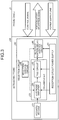
- FIG. 3 is an example of the configuration of the reception circuit 80 according to the first embodiment.
- the reception circuit 80 includes a reception circuit power supply 81, a reception control circuit 82, a preamplifier 83, and a received-portion delay-addition circuit 86.
- the reception circuit power supply 81 supplies a power supply to the preamplifier 83 and the received-portion delay-addition circuit 86.
- the reception control circuit 82 controls the preamplifier 83 and the received-portion delay-addition circuit 86.
- the preamplifier 83 includes a low noise amplifier 84 and a TGC (Time Gain Compensation) circuit 85, and adjusts the amplitude of a received reflected wave signal to an appropriate amplitude.
- the low noise circuit 84 is a low noise amplifier having a fixed amplification degree.
- the TGC circuit 85 changes the amplification degree during a reception period to reduce the amplification degree of a short-distance strong signal and increase the amplification degree of a long-distance weak signal. Therefore, the TGC circuit 85 prevents occurrence of practical saturation and noise characteristic degradation even when the dynamic range of the subsequent circuit is narrow.
- Delays that are different for each element are given to the received-portion delay-addition circuit 86, and the received-portion delay-addition circuit 86 adds signals of a plurality of elements together.
- the received-portion delay-addition circuit 86 adds signals of the elements so that the signals create directionality, thereby reducing the number of the signal lines.
- the final reception directionality is created in the receiving/scanning circuit 21. Delays of the respective elements at this time are adjusted depending on a direction that signals are desired to be received. According to the number of added elements, for example, when the number of elements is 4,000 and the number of channels of a probe cable is 200, addition is performed for every 20 elements so that the elements fall within the number of channels of the probe cable. In this way, signals are transmitted via the probe cable 3 and the connection unit 2 to the ultrasonic-diagnosis-apparatus main unit 10.
- the internal temperature of the ultrasonic probe 50 increases due to a loss caused by transmission of ultrasonic waves. Furthermore, in the reception circuit 80 within the ultrasonic probe 50, the internal temperature of the ultrasonic probe 50 increases because power is consumed by a bias current.
- the temperature of the acoustic module 51 or a casing of the ultrasonic probe 50 increases due to heat generated by a loss of an oscillating element, absorption of acoustic energy transmitted to a back surface by an attenuation material, a loss of acoustic energy in a substance interposed between a subject and the ultrasonic probe 50 such as rubber on an acoustic emission surface, and the like.
- the temperature sensors 53 to 55 for temperature detection are provided within the ultrasonic probe 50 to monitor the temperatures.
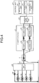
- FIG. 4 is an explanatory diagram of an operation of a switching process of the sensor line 57 by the control unit 40 according to the first embodiment.
- one ends of signal lines of the temperature sensors 53 to 55 that detect the temperature of the acoustic module 51, the temperature sensor 56 that detects the temperature of the electronic circuit 60, and the reference sensor 58 are commonly connected to the ground of a substrate of the electronic circuit 60.
- the other ends of the signal lines of the temperature sensors 53 to 56 and the reference sensor 58 are connected to the switching circuit 59.
- the switching circuit 59 is connected to one sensor line 57. That is, the switching circuit 59 reduces the number of the signal lines of the temperature sensors 53 to 56 and the reference sensor 58 to one sensor line 57.
- Control of the switching circuit 59 is executed by a control line connected to the ultrasonic-diagnosis-apparatus main unit 10.
- the switching circuit 59 validly connects a signal line of any one of the temperature sensors 53 to 56 and the reference sensor 58 that is designated by the control unit 40 to the sensor line 57.
- the sensor line 57 is then connected via the probe cable 3 to the connection unit 2.
- the ultrasonic probe 50 is connected via the connection unit 2 to the ultrasonic-diagnosis-apparatus main unit 10.
- a signal line to which the signal lines of the temperature sensors 53 to 56 and the reference sensor 58 are commonly connected is also connected via the probe cable 3 to the connection unit 2.
- the ultrasonic probe 50 is connected via the connection unit 2 to the ultrasonic-diagnosis-apparatus main unit 10.
- connection unit 2 there is a contact resistance between a connector 2a to the ultrasonic probe 50 connected to the sensor line 57 and a connector 2b to the ultrasonic-diagnosis-apparatus main unit 10. Further, in the connection unit 2, there is a contact resistance between a connector 2c to the other signal lines connected in common to the temperature sensors 53 to 56 and the reference sensor 58 and a connector 2d to the ultrasonic-diagnosis-apparatus main unit 10. These contact resistances are equal to or less than 1 ⁇ in a normal state. However, in a case of bad contact due to adhesion of dust or the like, a resistance of a few ohms is generated.
- the connectors 2b and 2d are connected to the temperature detector 30.
- the temperature detector 30 is then connected to the control unit 40.
- the temperature detector 30 measures the resistance value and then the temperature from the measured resistance value. The temperature detector 30 notifies the measured temperature to the control unit 40.
- the temperature detector 30 When the reference sensor 58 is selected, for example, when the difference between the resistance value and an expected value of the resistance value of the reference sensor is equal to or less than 1 ⁇ , the temperature detector 30 notifies the control unit 40 that the temperature is normal. On the other hand, when the reference sensor 58 is selected, for example, when it is detected that the difference in the resistance value is a few ohms, the temperature detector 30 notifies the control unit 40 that a temperature detection system is abnormal.
- control unit 40 includes the instruction unit 41, the determination unit 42, and the changing unit 43.
- the instruction unit 41 instructs the switching circuit 59 to switch connection to any one of the temperature sensors 53 to 56 and the reference sensor 58 to a valid state. For example, before scanning by the ultrasonic diagnosis apparatus 1 starts, the instruction unit 41 instructs the switching circuit 59 to switch connection to the reference sensor 58 to a valid state.
- the instruction unit 41 instructs the switching circuit 59 to switch connection to any one of the temperature sensors 53 to 56 to a valid state in a predetermined order.
- the determination unit 42 determines whether a connection state between connectors of the connection unit 2 is normal. For example, when the reference sensor 58 is selected and the determination unit 42 is notified by the temperature detector 30 that the temperature is normal, the determination unit 42 determines that a connection state between connectors of the connection unit 2 is normal. On the other hand, when the reference sensor 58 is selected and the determination unit 42 is notified by the temperature detector 30 that the temperature is abnormal, the determination unit 42 determines that a connection state between connectors of the connection unit 2 is abnormal. A case where a connection state between connectors of the connection unit 2 is normal refers to a case that connection between the switching circuit 59 and the temperature detector 30 and the control unit 40 is normal.
- the determination unit 42 permits the instruction unit 41 to switch connection to any one of the temperature sensors 53 to 56 to a valid state in a predetermined order.
- the determination unit 42 determines that the temperature of the ultrasonic probe 50 is abnormal.
- the changing unit 43 reduces power consumption of the ultrasonic diagnosis apparatus 1 lower than power consumption when it is determined that the temperature of the ultrasonic probe 50 is normal.
- the changing unit 43 changes the reduced power consumption to the power consumption before the reduction. Details of a process performed by the changing unit 43 are explained later with reference to FIG. 5 .
- FIG. 5 is a flowchart of an example of the process procedure performed by the control unit 40 according to the first embodiment.
- the instruction unit 41 controls the switching circuit 59 to cause the switching circuit 59 to select the reference sensor 58 (Step S101).
- the determination unit 42 determines whether a temperature measured by the temperature detector 30 is normal (Step S102).
- Step S102 determines that the measured temperature is not normal (NO at Step S102)
- the determination unit 42 informs a user of reinsertion of a connector (Step S103), and the process proceeds to Step S101.
- the control unit 40 can recognize a failure of a temperature detection system of the ultrasonic probe 50 and inform the user of reinsertion of the connector.
- the ultrasonic probe 50 can be energized to inform the user to prohibit the use thereof.
- the ultrasonic diagnosis apparatus 1 can thus maintain the safety of a subject.
- the reference sensor 58 When the reference sensor 58 is selected and measurement is performed, for example, there is a case where a slightly increased resistance value in which the difference between a resistance value of the reference sensor 58 and an expected value is 1.2 ⁇ and the like is measured repeatedly and stably. In such a case, the use of the ultrasonic probe 50 can be started after the resistance value of each sensor is corrected using an increase in the resistance. In this case, it is desirable to start using the ultrasonic probe 50 after displaying a caution for the user and correcting temperature detection.
- the determination unit 42 determines that the measured temperature is normal (YES at Step S102)
- the determination unit 42 energizes the ultrasonic probe 50 (Step S104).
- the ultrasonic diagnosis apparatus 1 thus starts to acquire image data.
- the instruction unit 41 instructs the switching circuit 59 to switch the temperature sensors 53 to 55 included in the acoustic module 51 at a fixed interval (Step S105).
- the determination unit 42 determines whether there is any abnormal temperature increase on a contact surface of the ultrasonic probe 50 with the subject (Step S106).
- the instruction unit 41 instructs the switching circuit 59 to switch to the reference sensor 58 (Step S107). In such a case, for example, a power consumption operation can be temporarily stopped.
- the determination unit 42 determines whether the temperature measured by the temperature detector 30 is normal (Step S108). When the determination unit 42 determines that the measured temperature is normal (YES at Step S108), the changing unit 43 reduces an acoustic output (Step S109) and suppresses received power (Step S110).
- the instruction unit 41 then instructs the switching circuit 59 to switch to the temperature sensors 53 to 56 that are determined by the determination unit 42 that the temperature has increased abnormally (Step S111).
- Step S111 In a state where an acoustic output is reduced and/or a state where power of the reception circuit 80 is suppressed, images are acquired and the determination unit 42 determines whether the temperature of the acoustic module 51 has decreased to a normal range (Step S112).
- the ultrasonic probe 50 is under normal control, generally, the temperature decreases.
- Step S113 the changing unit 43 returns the acoustic output level and the power of the reception circuit to the acoustic output level and the power of the reception circuit before the change (Step S113). After Step S113, the process proceeds to Step S105. In this way, the ultrasonic diagnosis apparatus 1 continues acquiring image data.
- the determination unit 42 determines at Step S108 that the measured temperature is not normal (NO at Step S108)
- the determination unit 42 causes the ultrasonic diagnosis apparatus 1 to stop acquisition of image data (Step S114), and the process ends.
- the determination unit 42 determines at Step S112 that the temperature has not decreased (NO at Step S112)
- the determination unit 42 causes the ultrasonic diagnosis apparatus 1 to stop acquisition of image data (Step S114), and the process ends.
- the control unit 40 determines whether the control unit 40 has acknowledged the end of scanning (Step S115).
- Step S115 When the control unit 40 determines that the control unit 40 has not acknowledged the end of scanning (NO at Step S115), the instruction unit 41 proceeds the process to Step S105, and instructs the switching circuit 59 to switch the temperature sensors 53 to 55. On the other hand, when the control unit 40 determines that the control unit 40 has acknowledged the end of scanning (YES at Step S115), the process ends.
- the number of signal lines can be reduced. Therefore, by allocating wires of a probe cable and pins of probe connectors to a plurality of temperature sensors, it is possible to prevent the probe cable from becoming large and heavy. According to the first embodiment, even when the number of temperature sensors is increased, the operability of an ultrasonic probe can be maintained.
- FIG. 6 is an example of a configuration of the probe cable 3 and the connection unit 2 when the switching circuit 59 is not included in the ultrasonic probe 50 and the number of temperature sensors is increased.
- Like constitution units as those shown in FIG. 4 are denoted by like reference signs.
- the respective signal lines of the temperature sensors 53 to 56 are connected via the probe cable 3 to the connection unit 2.
- the respective signal lines of the temperature sensors 53 to 56 are connected by connectors to the switching circuit 59 included in the ultrasonic-diagnosis-apparatus main unit 10.
- the signal lines from the temperature sensors 53 to 56 are made to be redundant and connected in parallel. Therefore, while there are four temperature sensors, there are nine connector pins in the connection unit 2. As explained above, by allocating wires of the probe cable 3 and pins of probe connectors to the respective temperature sensors, the probe cable 3 becomes large and heavy.
- the respective signal lines of the temperature sensors 53 to 56 are connected to the switching circuit 59, and only one sensor line 57 is allocated to the probe cable 3. Therefore, while there are four temperature sensors, there are four connectors in the connection unit 2. According to the ultrasonic diagnosis apparatus 1 of the first embodiment, it is possible to prevent the probe cable 3 from becoming large and heavy.
- the first embodiment has explained an example of temperature detection using a thermistor, even when other temperature detection elements are used, the same configuration can be realized. While an example of mounting the switching circuit 59 on the same substrate as transmission and reception circuits has been explained, even when the switching circuit 59 is mounted on a different substrate, identical effects can be achieved as long as a switch is provided on a side of a probe with respect to a probe cable connector.
- the control unit 40 shown in FIGS. 1 and 4 can be configured so as to include the instruction unit 41 and the determination unit 42 but not the changing unit 43.
- FIG. 7 is an example of a configuration of an ultrasonic diagnosis apparatus 1a according to the second embodiment.
- the ultrasonic diagnosis apparatus 1a according to the second embodiment includes an ultrasonic-diagnosis-apparatus main unit 10a and an ultrasonic probe 50a.
- Constituent elements identical to those of the respective elements shown in FIG. 1 are denoted by like reference signs and detailed explanations thereof will be omitted.
- FIG. 7 is different from FIG. 1 such that the ultrasonic-diagnosis-apparatus main unit 10a does not include the temperature detector 30 and the control unit 40.
- FIG. 8 is an explanatory diagram of an operation of a switching process of the sensor line 57 by the control unit 40 according to the second embodiment. Constituent elements identical to those of the respective elements shown in FIG. 4 are denoted by like reference signs and detailed explanations thereof will be omitted.
- FIG. 8 is different from FIG. 4 such that a signal line to which signal lines of the temperature sensors 53 to 56 and the reference sensor 58 are commonly connected is connected to the temperature detector 30.
- the temperature detector 30 is connected to the control unit 40 within the ultrasonic probe 50.
- a signal that is output by the switching circuit 59 to the sensor line is input from the connection unit 2 via the ultrasonic-diagnosis-apparatus main unit 10a to the temperature detector 30.
- a signal that is output by the switching circuit 59 to the sensor line is input via a path in which A and B in FIG. 8 are shortcircuited by a switch (not shown) and the like to the temperature detector 30.
- the ultrasonic diagnosis apparatus 1 can be also configured so that the ultrasonic probe 50 includes the temperature detector 30 and the ultrasonic-diagnosis-apparatus main unit 10a includes the control unit 40. Further, in the ultrasonic diagnosis apparatus 1, the respective units included in the control unit 40 can be distributed to the ultrasonic probe 50 and the ultrasonic-diagnosis-apparatus main unit 10a. In the ultrasonic diagnosis apparatus 1, functions included in the control unit 40 can be realized by an FPGA (Field-Programmable Gate Array) to reduce the weight of the ultrasonic diagnosis apparatus 1.
- FPGA Field-Programmable Gate Array
- the control unit 40 shown in FIG. 8 can be configured so as to include the instruction unit 41 and the determination unit 42 but not the changing unit 43.
- the number of signal lines can be reduced. Therefore, by allocating wires of a probe cable and pins of probe connectors to a plurality of temperature sensors, it is possible to prevent the probe cable from becoming large and heavy. Therefore, according to the second embodiment, even when the number of temperature sensors is increased, the operability of an ultrasonic probe can be maintained.
- a temperature sensor is incorporated in the acoustic module 51 to prevent a subject from having a burn when the temperature of the acoustic module 51 is abnormal. Therefore, it is desirable to design control of transmission and reception of ultrasonic waves and control of switching of temperature sensors independently from each other so that even when an abnormality occurs in control of transmission and reception of the ultrasonic diagnosis apparatus 1, a temperature abnormality is detectable. For example, in a case where the control of transmission and reception of ultrasonic waves cooperates with the control of switching of temperature sensors, when an abnormality occurs in the control of transmission and reception, there is a possibility that a temperature abnormality cannot be detected.
- the case where the control of transmission and reception of ultrasonic waves cooperates with the control of switching of temperature sensors refers to a case where, depending on ultrasonic transducer elements driven by scanning, connection to a temperature sensor that is installed near these ultrasonic transducer elements is switched to a valid state.
- an ultrasonic diagnosis apparatus 1b according to the third embodiment executes control of transmission and reception of ultrasonic waves and control of temperature sensors independently.
- the ultrasonic diagnosis apparatus 1b according to the third embodiment switches temperature sensors at a timing at which a temperature abnormality can be detected at a predetermined time interval.
- a configuration of the ultrasonic diagnosis apparatus 1b according to the third embodiment is the same as that of the ultrasonic diagnosis apparatus 1 shown in FIG. 1 except that a part of functions of the instruction unit 41 and the determination unit 42 is different. Therefore, detailed explanations of functional units other than the instruction unit 41 and the determination unit 42 according to the third embodiment will be omitted.
- the instruction unit 41 instructs the switching circuit 59 to switch connection to any one of a plurality of temperature sensors to a valid state at a predetermined time interval. For example, the instruction unit 41 outputs a switching signal that instructs the switching circuit 59 to switch connection to any one of the temperature sensors to a valid state to the switching circuit 59 at every predetermined time interval. The instruction unit 41 outputs a switching signal to the switching circuit 59 at a timing at which a temperature sensor can measure the temperature and detect a temperature abnormality at an appropriate time interval.
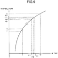
- FIG. 9 is an explanatory diagram of the process operation performed by the instruction unit 41 according to the third embodiment.
- FIG. 9 depicts a change in the temperature of an ultrasonic transducer element according to an elapsed time.
- the vertical axis indicates the temperature of an ultrasonic transducer element that is measured by a temperature sensor
- the horizontal axis indicates time.
- a change in the temperature of an ultrasonic transducer element according to an elapsed time shown in FIG. 9 (hereinafter, also "temperature increase speed”) is determined based on "heat capacity of ultrasonic transducer element" and "transmitted and received ultrasonic energy".
- the instruction unit 41 according to the third embodiment calculates a temperature increase speed in advance from at least one of the material and thickness of the ultrasonic probe 50 and the maximum value of energy available from the ultrasonic diagnosis apparatus 1b.
- the instruction unit 41 according to the third embodiment can hold the temperature increase speed derived in advance.
- the instruction unit 41 determines a predetermined time interval of instructing the switching circuit 59 to switch connection to any one of temperature sensors to a valid state based on the temperature increase speed. It suffices that the instruction unit 41 determines a time interval during which a fact that the temperature is increasing can be detected. For example, it suffices that the instruction unit 41 determines a predetermined time interval so that temperature sensors are switched at a timing faster than a temperature increase as shown in FIG. 9 . It is assumed that the range between a temperature T1 and a temperature T2 shown in FIG. 9 is a set temperature range in the ultrasonic diagnosis apparatus 1b. This set temperature range is a temperature range that is safe for a subject.
- the instruction unit 41 determines a time interval so that the temperature is measured for a fixed number of times within the set temperature range.
- this time interval is desirably an interval during which a curve of a temperature increase (degree of a temperature increase) is detected in the middle of the increase within the set temperature range.
- a temperature T3 at t1 is within the set temperature range.
- T4 is out of the set temperature range.
- a time interval is set so that after the temperature is measured at t1, the temperature is measured at t2, even when the temperature T3 measured at t1 is within the set temperature range, the temperature T4 measured at t2 may no longer be within the set temperature range.
- the instruction unit 41 determines a time interval of switching temperature sensors so that each temperature sensor measures the temperature for 1000 times per second. That is, in the ultrasonic diagnosis apparatus 1b, the instruction unit 41 switches temperature sensors for every 0.3 milliseconds and the temperature is measured by each temperature sensor. According to an example shown in FIG. 9 , the temperature starts to be measured at t1 and is measured by the temperature sensor A for every millisecond. In the ultrasonic diagnosis apparatus 1b, the temperature is measured by three temperature sensors for 3,000 times in total per second. For example, as shown in FIG. 9 , after the temperature starts to be measured at t1 by the temperature sensor A, the temperature is measured by the temperature sensor A for every millisecond.
- T5 When it is assumed that a temperature measured by the temperature sensor A at t11 is indicated as T5, this temperature T5 is within the set temperature range. Further, when it is assumed that a temperature measured by the temperature sensor A at t12 after a millisecond from t11 is indicated as T6, this temperature T6 is also within the set temperature range. On the other hand, when it is assumed that a temperature measured by the temperature sensor A at t13 after a millisecond from t2 is indicated as T7, the temperature T7 is out of the set temperature range.
- the instruction unit 41 outputs a switching signal that instructs the switching circuit 59 to switch connection to any one of temperature sensors to a valid state at a time interval during which a curve of a temperature increase (the degree of a temperature increase) is detected in the middle of the increase within the set temperature range to the switching circuit 59. Accordingly, even when capturing is performed at the maximum value of energy available from the ultrasonic diagnosis apparatus 1b, it is possible to detect whether the ultrasonic probe 50 is within the set temperature range.
- a switching signal is input to the reception circuit 80. That is, by switching the temperature sensors by the instruction unit 41, electric noise is input to the reception circuit 80. In such a case, a bright point is formed at a position of an ultrasonic image where a reflector is not present. Therefore, the instruction unit 41 adjusts a timing so as not to instruct the switching circuit 59 to switch temperature sensors during a period in which the reception circuit 80 receives a reflected wave signal. For example, the instruction unit 41 instructs the switching circuit 59 to switch temperature sensors at a timing at which an ultrasonic wave is transmitted.
- the instruction unit 41 according to the third embodiment instructs the switching circuit 59 to switch the temperature sensors 53 to 55 included in the acoustic module 51 at a predetermined time interval. While the third embodiment has explained that the instruction unit 41 determines the time interval, the embodiment is not limited thereto.
- the instruction unit 41 according to the third embodiment can be configured so as to hold a time interval derived in advance and output a switching signal that instructs the switching circuit 59 to switch connection to any one of a plurality of temperature sensors to a valid state to the switching circuit 59 at this timer interval.
- the ultrasonic diagnosis apparatus 1b executes control of transmission and reception of ultrasonic waves and control of temperature sensors independently, and instructs the switching circuit 59 to switch connection to any one of temperature sensors to a valid state at a predetermined time interval. According to the third embodiment, it is possible to detect a fact that the temperature is increasing within a set temperature range.
- the ultrasonic diagnosis apparatus when the control of transmission and reception of ultrasonic waves cooperates with the control of switching of temperature sensors, as a capturing cycle becomes longer, it becomes more difficult to appropriately switch the temperature sensors.
- the ultrasonic diagnosis apparatus captures the same portion to acquire an average speed (or the maximum speed), a speed distribution (or a speed distribution width), scattering power information from a blood flow, and the like. For this reason, to acquire Doppler image information, the ultrasonic diagnosis apparatus captures a fixed area at a cycle of, for example, 100 milliseconds.
- the number of captures per second may be one or two.
- a timing of switching the temperature sensors becomes slower than a timing when Doppler image information is an observation target, and it is impossible to detect a temperature increase.
- temperature sensors can be arranged in multiple lines, for example, three lines.
- the determination unit 42 can be configured so as to determine that the temperature of the ultrasonic probe 50 is abnormal when a temperature measured by the temperature detector 30 is out of a set temperature range. Also in such a case, the ultrasonic diagnosis apparatus 1b can further determine whether a connection state between connectors of the connection unit 2 is normal. For example, when it is determined by the determination unit 42 that a temperature measured by a temperature sensor whose connection is in a valid state is out of the set temperature range, the instruction unit 41 instructs the switching circuit 59 to switch connection to the reference sensor 58 to a valid state. When connection to the reference sensor 58 is in a valid state and connection of the temperature detector 30 and the control unit 40 is normal, the determination unit 42 determines that the temperature of the ultrasonic probe 50 is abnormal.
- the determination unit 42 can detect a fact that the temperature is increasing within the set temperature range. For example, when a temperature measured by the temperature detector 30 is within the set temperature range and the difference between this temperature and a previously measured temperature is equal to or larger than a predetermined threshold, the determination unit 42 can determine that the temperature of the ultrasonic probe 50 is abnormal. Therefore, for example, even when the temperature changes rapidly, the ultrasonic diagnosis apparatus 1b can prevent a subject from having a burn. Also in such a case, the ultrasonic diagnosis apparatus 1b can further determine whether a connection state between connectors of the connection unit 2 is normal.
- the instruction unit 41 instructs the switching circuit 59 to switch connection to the reference sensor 58 to a valid state.
- the determination unit 42 determines that the temperature of the ultrasonic probe 50 is abnormal.
- the determination unit 42 can determine that the temperature of the ultrasonic probe 50 is abnormal. Therefore, for example, even when the temperature continuously increases, the ultrasonic diagnosis apparatus 1b can prevent a subject from having a burn. Also in such a case, the ultrasonic diagnosis apparatus 1b can further determine whether a connection state between connectors of the connection unit 2 is normal. For example, when it is determined by the determination unit 42 that the temperature continuously increases for a predetermined period, the instruction unit 41 instructs the switching circuit 59 to switch connection to the reference sensor 58 to a valid state. When connection to the reference sensor 58 is in a valid state and connection of the temperature detector 30 and the control unit 40 is normal, the determination unit 42 determines that the temperature of the ultrasonic probe 50 is abnormal.
Landscapes
- Health & Medical Sciences (AREA)
- Life Sciences & Earth Sciences (AREA)
- Engineering & Computer Science (AREA)
- Medical Informatics (AREA)
- Biophysics (AREA)
- Nuclear Medicine, Radiotherapy & Molecular Imaging (AREA)
- Pathology (AREA)
- Radiology & Medical Imaging (AREA)
- Veterinary Medicine (AREA)
- Biomedical Technology (AREA)
- Heart & Thoracic Surgery (AREA)
- Physics & Mathematics (AREA)
- Molecular Biology (AREA)
- Surgery (AREA)
- Animal Behavior & Ethology (AREA)
- General Health & Medical Sciences (AREA)
- Public Health (AREA)
- Hematology (AREA)
- Ultra Sonic Daignosis Equipment (AREA)
Claims (18)
- Ultraschall-Diagnosevorrichtung (1), umfassend:eine Ultraschallsonde (50), die konfiguriert ist, um eine Ultraschallwelle zu einem Probanden zu senden und von ihm zu empfangen;eine Bilderzeugungseinheit (22), die konfiguriert ist, um Bilddaten von einer reflektierten Welle zu erzeugen, die von der Ultraschallsonde empfangen wird (50);eine Anzeigeeinheit (25), die konfiguriert ist, um die Bilddaten anzuzeigen; undeine Steuereinheit (40), die konfiguriert ist, um Übertragung und Empfang einer Ultraschallwelle durch die Ultraschallsonde (50) zu steuern,eine Vielzahl von Temperatursensoren (53 bis 56), die an einer Vielzahl von Positionen innerhalb der Ultraschallsonde (50) eingebaut sind, eine Bestimmungseinheit (42), die in der Steuereinheit (40) eingeschlossen ist, konfiguriert, um zu bestimmen, ob eine durch einen Temperaturdetektor (30) gemessene Temperatur innerhalb eines festgelegten Temperaturbereichs liegt, dadurch gekennzeichnet, dass die Ultraschallvorrichtung ferner umfasst:einen Schaltkreis (59), der in der Ultraschallsonde (50) eingeschlossen ist, konfiguriert, um mit den jeweiligen Temperatursensoren (53 bis 56) verbunden zu sein, und konfiguriert ist, um eine Verbindung zu einem der Temperatursensoren (53 bis 56) auf einen gültigen Zustand zu schalten, um nacheinander Daten von den jeweiligen Temperatursensoren (53 bis 56) an den Temperaturdetektor (30) auszugeben, der eine Temperatur unter Verwendung von Ausgabedaten des Temperatursensors (53 bis 56) misst,eine Befehlseinheit (41), die in der Steuereinheit (40) eingeschlossen ist, konfiguriert, den Schaltkreis (59) anzuweisen, eine Verbindung zu einem der Temperatursensoren (53 bis 56) in einem vorbestimmten Zeitintervall auf einen gültigen Zustand zu schalten.
- Ultraschalldiagnosevorrichtung (1) nach Anspruch 1, wobei die Befehlseinheit (41) konfiguriert ist, um den Schaltkreis (59) anzuweisen, die Verbindung zu einem von einer Vielzahl von Temperatursensoren (53 bis 56) in dem vorbestimmten Zeitintervall, das basierend auf einer Temperaturerhöhungsgeschwindigkeit bestimmt wird, auf einen gültigen Zustand zu schalten.
- Ultraschalldiagnosevorrichtung (1) nach Anspruch 2, wobei die Temperaturerhöhungsgeschwindigkeit basierend auf mindestens einem von einem Material und einer Dicke der Ultraschallsonde (50) und übertragener und empfangener Ultraschallenergie abgeleitet wird.
- Ultraschalldiagnosevorrichtung (1) nach einem der Ansprüche 1 bis 3, wobei
die Ultraschallsonde (50) ferner einen Referenzsensor (58) einschließt, der konfiguriert ist, Daten für den Temperaturdetektor (30) auszugeben, um zu erfassen, ob die Verbindung des Temperaturdetektors (30) und der Steuereinheit (40) normal ist.
der Schaltkreis (59) ferner konfiguriert ist, um mit dem Referenzsensor (58) verbunden zu sein, und konfiguriert ist, um die Verbindung zu einem der Temperatursensoren (53 bis 56) und dem Referenzsensor (58) auf einen gültigen Zustand zu schalten, um nacheinander Ausgabedaten der jeweiligen Sensoren an den Temperaturdetektor (30) auszugeben,
wobei die Befehlseinheit (41) konfiguriert ist, den Schaltkreis (59) anzuweisen, die Verbindung zu einem der Temperatursensoren (53 bis 56) und dem Referenzsensor (58) in dem vorbestimmten Zeitintervall auf einen gültigen Zustand zu schalten, und
wenn die Verbindung zu dem Referenzsensor (58) in einem gültigen Zustand ist und die Verbindung des Temperaturdetektors (30) und der Steuereinheit (40) normal ist, die Bestimmungseinheit (42) konfiguriert ist, um es der Befehlseinheit (41) zu ermöglichen, die Verbindung zu einem der Temperatursensoren (53 bis 56) auf einen gültigen Zustand zu schalten. - Ultraschalldiagnosevorrichtung (1) nach einem der Ansprüche 1 bis 4, wobei, wenn eine von dem Temperaturdetektor (30) gemessene Temperatur außerhalb des festgelegten Temperaturbereichs liegt, die Bestimmungseinheit (42) konfiguriert ist, zu bestimmen, dass eine Temperatur der Ultraschallsonde (50) abnormal ist.
- Ultraschalldiagnosevorrichtung (1) nach einem der Ansprüche 1 bis 4, wobei, wenn eine von dem Temperaturdetektor (30) gemessene Temperatur innerhalb des festgelegten Temperaturbereichs liegt und eine Differenz zwischen der Temperatur und einer zuvor gemessenen Temperatur gleich oder größer als ein vorbestimmter Schwellenwert ist, die Bestimmungseinheit (42) konfiguriert ist, zu bestimmen, dass eine Temperatur der Ultraschallsonde (50) abnormal ist.
- Ultraschalldiagnosevorrichtung (1) nach einem der Ansprüche 1 bis 4, wobei, wenn eine von dem Temperaturdetektor (30) gemessene Temperatur innerhalb des festgelegten Temperaturbereichs liegt und eine Temperatur sich für einen vorbestimmten Zeitraum kontinuierlich erhöht, die Bestimmungseinheit (42) konfiguriert ist, zu bestimmen, dass eine Temperatur der Ultraschallsonde (50) abnormal ist.
- Ultraschalldiagnosevorrichtung (1) nach Anspruch 4, wobei,
wenn durch die Bestimmungseinheit (42) bestimmt wird, dass eine Temperatur, die von dem Temperatursensor (53 bis 56) gemessen wird, dessen Verbindung in einem gültigen Zustand ist, außerhalb des festgelegten Temperaturbereichs liegt, die Befehlseinheit (41) konfiguriert ist, den Schaltkreis (59) anzuweisen, die Verbindung zu dem Referenzsensor (58) auf einen gültigen Zustand zu schalten, und
wenn die Verbindung zu dem Referenzsensor (58) in einem gültigen Zustand ist und die Verbindung des Temperaturdetektors (30) und der Steuereinheit (40) normal ist, die Bestimmungseinheit (42) konfiguriert ist, zu bestimmen, dass eine Temperatur der Ultraschallsonde (50) abnormal ist. - Ultraschalldiagnosevorrichtung (1) nach Anspruch 4 oder 8, wobei,
wenn durch die Bestimmungseinheit (42) bestimmt wird, dass eine von dem Temperaturdetektor (30) gemessene Temperatur innerhalb des festgelegten Temperaturbereichs liegt und eine Differenz zwischen der Temperatur und einer zuvor gemessenen Temperatur gleich oder größer als ein vorbestimmter Schwellenwert ist, die Befehlseinheit (41) konfiguriert ist, den Schaltkreis (59) anzuweisen, die Verbindung zu dem Referenzsensor (58) auf einen gültigen Zustand zu schalten, und
wenn die Verbindung zu dem Referenzsensor (58) in einem gültigen Zustand ist und die Verbindung des Temperaturdetektors (30) und der Steuereinheit (40) normal ist, die Bestimmungseinheit (42) konfiguriert ist, zu bestimmen, dass eine Temperatur der Ultraschallsonde (50) abnormal ist. - Ultraschalldiagnosevorrichtung (1) nach Anspruch 4 oder 8, wobei,
wenn durch die Bestimmungseinheit (42) bestimmt wird, dass eine von dem Temperaturdetektor (30) gemessene Temperatur innerhalb des festgelegten Temperaturbereichs liegt und eine Temperatur für einen vorbestimmten Zeitraum kontinuierlich steigt, die Befehlseinheit (41) konfiguriert ist, den Schaltkreis (59) anzuweisen, die Verbindung zu dem Referenzsensor (58) auf einen gültigen Zustand zu schalten, und
wenn die Verbindung zu dem Referenzsensor (58) in einem gültigen Zustand ist und die Verbindung des Temperaturdetektors (30) und der Steuereinheit (40) normal ist, die Bestimmungseinheit (42) konfiguriert ist, zu bestimmen, dass eine Temperatur der Ultraschallsonde (50) abnormal ist. - Ultraschalldiagnosevorrichtung (1) nach einem der Ansprüche 5 bis 10, wobei, wenn die Bestimmungseinheit (42) konfiguriert ist, zu bestimmen, dass eine Temperatur der Ultraschallsonde (50) abnormal ist, die Bestimmungseinheit (42) konfiguriert ist, einen Benutzer zu informieren, dass die Temperatur der Ultraschallsonde (50) abnormal ist.
- Ultraschalldiagnosevorrichtung (1) nach einem der Ansprüche 5 bis 11, wobei, wenn die Bestimmungseinheit (42) bestimmt, dass eine Temperatur der Ultraschallsonde (50) abnormal ist, die Bestimmungseinheit (42) konfiguriert ist, die Verwendung der Ultraschallsonde (50) zu stoppen.
- Ultraschalldiagnosevorrichtung (1) nach einem der Ansprüche 5 bis 12, ferner umfassend eine Wechseleinheit (43), die, wenn von der Bestimmungseinheit (42) bestimmt wird, dass eine Temperatur der Ultraschallsonde (50) abnormal ist, konfiguriert ist, den Stromverbrauch der Ultraschalldiagnosevorrichtung (1) mehr als den Stromverbrauch zu einem Zeitpunkt zu reduzieren, an dem bestimmt wird, dass die Temperatur der Ultraschallsonde (50) abnormal ist.
- Ultraschalldiagnosevorrichtung (1) nach Anspruch 13, wobei,
nachdem ein Verfahren zum Reduzieren des Stromverbrauchs durch die Wechseleinheit (43) ausgeführt wird, wenn eine Verbindung zum Temperatursensor (53 bis 56) in einem gültigen Zustand ist und eine von dem Temperatursensor (53 bis 56) gemessene Temperatur innerhalb des festgelegten Temperaturbereichs liegt, die Bestimmungseinheit (42) konfiguriert ist, zu bestimmen, dass eine Diagnose durch die Ultraschalldiagnosevorrichtung (1) durchgeführt werden kann, und
wenn durch die Bestimmungseinheit (42) bestimmt wird, dass eine Diagnose durch die Ultraschalldiagnosevorrichtung (1) durchgeführt werden kann, die Wechseleinheit (43) konfiguriert ist, einen reduzierten Stromverbrauch zu einem Stromverbrauch vor der Reduzierung zu ändern. - Ultraschalldiagnosevorrichtung (1) nach einem der Ansprüche 1 bis 14, wobei ein Ende der Signalleitungen der Temperatursensoren (53 bis 56) konfiguriert ist, mit dem Schaltkreis (59) verbunden zu sein, und die anderen Enden der Signalleitungen der Temperatursensoren (53 bis 56) üblicherweise mit einer Masse verbunden sind.
- Ultraschalldiagnosevorrichtung (1) nach einem der Ansprüche 1 bis 15, wobei
die Temperatursensoren (53 bis 56) durch eine Vielzahl von ersten Temperatursensoren (53 bis 56) gebildet sind, die an einer Vielzahl von Positionen eines in der Ultraschallsonde (50) eingeschlossenen Akustikmoduls (51) eingebaut sind, und
mindestens ein zweiter Temperatursensor (56), der in einer elektronischen Schaltung (60) eingebaut ist, in der Ultraschallsonde (50) eingeschlossen ist. - Ultraschalldiagnosevorrichtung (1) nach einem der Ansprüche 1 bis 16, wobei der Temperatursensor (53 bis 56) ein Thermistor ist.
- Ultraschalldiagnosevorrichtung (1) nach einem der Ansprüche 1 bis 17, wobei die Ultraschallsonde (50) die Steuereinheit (40) einschließlich der Befehlseinheit (41) und der Bestimmungseinheit (42) einschließt.
Applications Claiming Priority (2)
| Application Number | Priority Date | Filing Date | Title |
|---|---|---|---|
| JP2012231884 | 2012-10-19 | ||
| PCT/JP2013/078382 WO2014061806A1 (ja) | 2012-10-19 | 2013-10-18 | 超音波診断装置及び超音波探触子 |
Publications (3)
| Publication Number | Publication Date |
|---|---|
| EP2896370A1 EP2896370A1 (de) | 2015-07-22 |
| EP2896370A4 EP2896370A4 (de) | 2016-07-06 |
| EP2896370B1 true EP2896370B1 (de) | 2019-12-18 |
Family
ID=53396086
Family Applications (1)
| Application Number | Title | Priority Date | Filing Date |
|---|---|---|---|
| EP13846873.1A Active EP2896370B1 (de) | 2012-10-19 | 2013-10-18 | Ultraschalldiagnosevorrichtung und ultraschallsonde |
Country Status (1)
| Country | Link |
|---|---|
| EP (1) | EP2896370B1 (de) |
Families Citing this family (2)
| Publication number | Priority date | Publication date | Assignee | Title |
|---|---|---|---|---|
| US11937984B2 (en) * | 2020-08-25 | 2024-03-26 | GE Precision Healthcare LLC | Active ingress detection system for medical probes |
| CN117322957B (zh) * | 2023-12-01 | 2024-02-06 | 深圳腾复医疗科技有限公司 | 超声消融电路及包含其的装置 |
Family Cites Families (4)
| Publication number | Priority date | Publication date | Assignee | Title |
|---|---|---|---|---|
| EP1899720A2 (de) * | 2005-06-29 | 2008-03-19 | Koninklijke Philips Electronics N.V. | Optimierte temperaturmessung in einem ultraschallwandler |
| JP2008188162A (ja) * | 2007-02-02 | 2008-08-21 | Toshiba Corp | 超音波診断装置、及び超音波プローブ |
| WO2008146208A2 (en) * | 2007-06-01 | 2008-12-04 | Koninklijke Philips Electronics, N.V. | Wireless ultrasound probe with energy conservation |
| JP5099681B2 (ja) * | 2007-06-29 | 2012-12-19 | ジーイー・メディカル・システムズ・グローバル・テクノロジー・カンパニー・エルエルシー | 超音波探触子、超音波診断装置および超音波探触子の表面温度推定方法 |
-
2013
- 2013-10-18 EP EP13846873.1A patent/EP2896370B1/de active Active
Non-Patent Citations (1)
| Title |
|---|
| None * |
Also Published As
| Publication number | Publication date |
|---|---|
| EP2896370A4 (de) | 2016-07-06 |
| EP2896370A1 (de) | 2015-07-22 |
Similar Documents
| Publication | Publication Date | Title |
|---|---|---|
| US10226237B2 (en) | Ultrasonic diagnosis apparatus and ultrasonic probe | |
| US9168019B2 (en) | Ultrasonic diagnostic device | |
| US8764662B2 (en) | Ultrasound imaging system and method for temperature management | |
| KR102635039B1 (ko) | 초음파 장치 및 그 제어 방법 | |
| JP5771293B2 (ja) | 超音波診断装置 | |
| WO2013031580A1 (ja) | 超音波プローブ及び超音波診断装置 | |
| EP2896370B1 (de) | Ultraschalldiagnosevorrichtung und ultraschallsonde | |
| JP5510449B2 (ja) | 超音波診断装置 | |
| EP3480621B1 (de) | Ultraschallvorrichtung und steuerungsverfahren dafür | |
| US10485519B2 (en) | Ultrasonic diagnostic apparatus, biological signal acquisition apparatus and method for controlling ultrasonic diagnostic apparatus | |
| JP2004275545A (ja) | 超音波診断装置 | |
| KR102627724B1 (ko) | 초음파 장치 및 그 제어 방법 | |
| JP2013158478A (ja) | 携帯型超音波診断装置 | |
| JP2015181796A (ja) | 測定装置、測定方法、および超音波診断装置 | |
| JPH02291846A (ja) | 超音波診断装置 |
Legal Events
| Date | Code | Title | Description |
|---|---|---|---|
| PUAI | Public reference made under article 153(3) epc to a published international application that has entered the european phase |
Free format text: ORIGINAL CODE: 0009012 |
|
| 17P | Request for examination filed |
Effective date: 20150417 |
|
| AK | Designated contracting states |
Kind code of ref document: A1 Designated state(s): AL AT BE BG CH CY CZ DE DK EE ES FI FR GB GR HR HU IE IS IT LI LT LU LV MC MK MT NL NO PL PT RO RS SE SI SK SM TR |
|
| AX | Request for extension of the european patent |
Extension state: BA ME |
|
| DAX | Request for extension of the european patent (deleted) | ||
| RA4 | Supplementary search report drawn up and despatched (corrected) |
Effective date: 20160606 |
|
| RIC1 | Information provided on ipc code assigned before grant |
Ipc: A61B 8/08 20060101ALI20160531BHEP Ipc: A61B 8/00 20060101AFI20160531BHEP Ipc: A61B 8/06 20060101ALI20160531BHEP |
|
| RAP1 | Party data changed (applicant data changed or rights of an application transferred) |
Owner name: TOSHIBA MEDICAL SYSTEMS CORPORATION |
|
| GRAP | Despatch of communication of intention to grant a patent |
Free format text: ORIGINAL CODE: EPIDOSNIGR1 |
|
| STAA | Information on the status of an ep patent application or granted ep patent |
Free format text: STATUS: GRANT OF PATENT IS INTENDED |
|
| INTG | Intention to grant announced |
Effective date: 20190627 |
|
| GRAS | Grant fee paid |
Free format text: ORIGINAL CODE: EPIDOSNIGR3 |
|
| GRAA | (expected) grant |
Free format text: ORIGINAL CODE: 0009210 |
|
| STAA | Information on the status of an ep patent application or granted ep patent |
Free format text: STATUS: THE PATENT HAS BEEN GRANTED |
|
| RAP1 | Party data changed (applicant data changed or rights of an application transferred) |
Owner name: TOSHIBA MEDICAL SYSTEMS CORPORATION |
|
| AK | Designated contracting states |
Kind code of ref document: B1 Designated state(s): AL AT BE BG CH CY CZ DE DK EE ES FI FR GB GR HR HU IE IS IT LI LT LU LV MC MK MT NL NO PL PT RO RS SE SI SK SM TR |
|
| REG | Reference to a national code |
Ref country code: CH Ref legal event code: EP |
|
| REG | Reference to a national code |
Ref country code: IE Ref legal event code: FG4D |
|
| REG | Reference to a national code |
Ref country code: DE Ref legal event code: R096 Ref document number: 602013064208 Country of ref document: DE |
|
| REG | Reference to a national code |
Ref country code: AT Ref legal event code: REF Ref document number: 1213680 Country of ref document: AT Kind code of ref document: T Effective date: 20200115 |
|
| REG | Reference to a national code |
Ref country code: NL Ref legal event code: FP |
|
| PG25 | Lapsed in a contracting state [announced via postgrant information from national office to epo] |
Ref country code: LV Free format text: LAPSE BECAUSE OF FAILURE TO SUBMIT A TRANSLATION OF THE DESCRIPTION OR TO PAY THE FEE WITHIN THE PRESCRIBED TIME-LIMIT Effective date: 20191218 Ref country code: SE Free format text: LAPSE BECAUSE OF FAILURE TO SUBMIT A TRANSLATION OF THE DESCRIPTION OR TO PAY THE FEE WITHIN THE PRESCRIBED TIME-LIMIT Effective date: 20191218 Ref country code: NO Free format text: LAPSE BECAUSE OF FAILURE TO SUBMIT A TRANSLATION OF THE DESCRIPTION OR TO PAY THE FEE WITHIN THE PRESCRIBED TIME-LIMIT Effective date: 20200318 Ref country code: FI Free format text: LAPSE BECAUSE OF FAILURE TO SUBMIT A TRANSLATION OF THE DESCRIPTION OR TO PAY THE FEE WITHIN THE PRESCRIBED TIME-LIMIT Effective date: 20191218 Ref country code: BG Free format text: LAPSE BECAUSE OF FAILURE TO SUBMIT A TRANSLATION OF THE DESCRIPTION OR TO PAY THE FEE WITHIN THE PRESCRIBED TIME-LIMIT Effective date: 20200318 Ref country code: GR Free format text: LAPSE BECAUSE OF FAILURE TO SUBMIT A TRANSLATION OF THE DESCRIPTION OR TO PAY THE FEE WITHIN THE PRESCRIBED TIME-LIMIT Effective date: 20200319 Ref country code: LT Free format text: LAPSE BECAUSE OF FAILURE TO SUBMIT A TRANSLATION OF THE DESCRIPTION OR TO PAY THE FEE WITHIN THE PRESCRIBED TIME-LIMIT Effective date: 20191218 |
|
| REG | Reference to a national code |
Ref country code: LT Ref legal event code: MG4D |
|
| PG25 | Lapsed in a contracting state [announced via postgrant information from national office to epo] |
Ref country code: HR Free format text: LAPSE BECAUSE OF FAILURE TO SUBMIT A TRANSLATION OF THE DESCRIPTION OR TO PAY THE FEE WITHIN THE PRESCRIBED TIME-LIMIT Effective date: 20191218 Ref country code: RS Free format text: LAPSE BECAUSE OF FAILURE TO SUBMIT A TRANSLATION OF THE DESCRIPTION OR TO PAY THE FEE WITHIN THE PRESCRIBED TIME-LIMIT Effective date: 20191218 |
|
| PG25 | Lapsed in a contracting state [announced via postgrant information from national office to epo] |
Ref country code: AL Free format text: LAPSE BECAUSE OF FAILURE TO SUBMIT A TRANSLATION OF THE DESCRIPTION OR TO PAY THE FEE WITHIN THE PRESCRIBED TIME-LIMIT Effective date: 20191218 |
|
| PG25 | Lapsed in a contracting state [announced via postgrant information from national office to epo] |
Ref country code: EE Free format text: LAPSE BECAUSE OF FAILURE TO SUBMIT A TRANSLATION OF THE DESCRIPTION OR TO PAY THE FEE WITHIN THE PRESCRIBED TIME-LIMIT Effective date: 20191218 Ref country code: RO Free format text: LAPSE BECAUSE OF FAILURE TO SUBMIT A TRANSLATION OF THE DESCRIPTION OR TO PAY THE FEE WITHIN THE PRESCRIBED TIME-LIMIT Effective date: 20191218 Ref country code: PT Free format text: LAPSE BECAUSE OF FAILURE TO SUBMIT A TRANSLATION OF THE DESCRIPTION OR TO PAY THE FEE WITHIN THE PRESCRIBED TIME-LIMIT Effective date: 20200513 Ref country code: CZ Free format text: LAPSE BECAUSE OF FAILURE TO SUBMIT A TRANSLATION OF THE DESCRIPTION OR TO PAY THE FEE WITHIN THE PRESCRIBED TIME-LIMIT Effective date: 20191218 |
|
| PG25 | Lapsed in a contracting state [announced via postgrant information from national office to epo] |
Ref country code: SM Free format text: LAPSE BECAUSE OF FAILURE TO SUBMIT A TRANSLATION OF THE DESCRIPTION OR TO PAY THE FEE WITHIN THE PRESCRIBED TIME-LIMIT Effective date: 20191218 Ref country code: SK Free format text: LAPSE BECAUSE OF FAILURE TO SUBMIT A TRANSLATION OF THE DESCRIPTION OR TO PAY THE FEE WITHIN THE PRESCRIBED TIME-LIMIT Effective date: 20191218 Ref country code: IS Free format text: LAPSE BECAUSE OF FAILURE TO SUBMIT A TRANSLATION OF THE DESCRIPTION OR TO PAY THE FEE WITHIN THE PRESCRIBED TIME-LIMIT Effective date: 20200418 |
|
| REG | Reference to a national code |
Ref country code: DE Ref legal event code: R097 Ref document number: 602013064208 Country of ref document: DE |
|
| REG | Reference to a national code |
Ref country code: AT Ref legal event code: MK05 Ref document number: 1213680 Country of ref document: AT Kind code of ref document: T Effective date: 20191218 |
|
| PLBE | No opposition filed within time limit |
Free format text: ORIGINAL CODE: 0009261 |
|
| STAA | Information on the status of an ep patent application or granted ep patent |
Free format text: STATUS: NO OPPOSITION FILED WITHIN TIME LIMIT |
|
| PG25 | Lapsed in a contracting state [announced via postgrant information from national office to epo] |
Ref country code: DK Free format text: LAPSE BECAUSE OF FAILURE TO SUBMIT A TRANSLATION OF THE DESCRIPTION OR TO PAY THE FEE WITHIN THE PRESCRIBED TIME-LIMIT Effective date: 20191218 Ref country code: ES Free format text: LAPSE BECAUSE OF FAILURE TO SUBMIT A TRANSLATION OF THE DESCRIPTION OR TO PAY THE FEE WITHIN THE PRESCRIBED TIME-LIMIT Effective date: 20191218 |
|
| 26N | No opposition filed |
Effective date: 20200921 |
|
| PG25 | Lapsed in a contracting state [announced via postgrant information from national office to epo] |
Ref country code: AT Free format text: LAPSE BECAUSE OF FAILURE TO SUBMIT A TRANSLATION OF THE DESCRIPTION OR TO PAY THE FEE WITHIN THE PRESCRIBED TIME-LIMIT Effective date: 20191218 Ref country code: SI Free format text: LAPSE BECAUSE OF FAILURE TO SUBMIT A TRANSLATION OF THE DESCRIPTION OR TO PAY THE FEE WITHIN THE PRESCRIBED TIME-LIMIT Effective date: 20191218 |
|
| PG25 | Lapsed in a contracting state [announced via postgrant information from national office to epo] |
Ref country code: IT Free format text: LAPSE BECAUSE OF FAILURE TO SUBMIT A TRANSLATION OF THE DESCRIPTION OR TO PAY THE FEE WITHIN THE PRESCRIBED TIME-LIMIT Effective date: 20191218 |
|
| PG25 | Lapsed in a contracting state [announced via postgrant information from national office to epo] |
Ref country code: PL Free format text: LAPSE BECAUSE OF FAILURE TO SUBMIT A TRANSLATION OF THE DESCRIPTION OR TO PAY THE FEE WITHIN THE PRESCRIBED TIME-LIMIT Effective date: 20191218 |
|
| REG | Reference to a national code |
Ref country code: CH Ref legal event code: PL |
|
| GBPC | Gb: european patent ceased through non-payment of renewal fee |
Effective date: 20201018 |
|
| PG25 | Lapsed in a contracting state [announced via postgrant information from national office to epo] |
Ref country code: MC Free format text: LAPSE BECAUSE OF FAILURE TO SUBMIT A TRANSLATION OF THE DESCRIPTION OR TO PAY THE FEE WITHIN THE PRESCRIBED TIME-LIMIT Effective date: 20191218 Ref country code: LU Free format text: LAPSE BECAUSE OF NON-PAYMENT OF DUE FEES Effective date: 20201018 |
|
| REG | Reference to a national code |
Ref country code: BE Ref legal event code: MM Effective date: 20201031 |
|
| PG25 | Lapsed in a contracting state [announced via postgrant information from national office to epo] |
Ref country code: FR Free format text: LAPSE BECAUSE OF NON-PAYMENT OF DUE FEES Effective date: 20201031 |
|
| PG25 | Lapsed in a contracting state [announced via postgrant information from national office to epo] |
Ref country code: LI Free format text: LAPSE BECAUSE OF NON-PAYMENT OF DUE FEES Effective date: 20201031 Ref country code: GB Free format text: LAPSE BECAUSE OF NON-PAYMENT OF DUE FEES Effective date: 20201018 Ref country code: CH Free format text: LAPSE BECAUSE OF NON-PAYMENT OF DUE FEES Effective date: 20201031 Ref country code: BE Free format text: LAPSE BECAUSE OF NON-PAYMENT OF DUE FEES Effective date: 20201031 |
|
| PG25 | Lapsed in a contracting state [announced via postgrant information from national office to epo] |
Ref country code: IE Free format text: LAPSE BECAUSE OF NON-PAYMENT OF DUE FEES Effective date: 20201018 |
|
| PG25 | Lapsed in a contracting state [announced via postgrant information from national office to epo] |
Ref country code: TR Free format text: LAPSE BECAUSE OF FAILURE TO SUBMIT A TRANSLATION OF THE DESCRIPTION OR TO PAY THE FEE WITHIN THE PRESCRIBED TIME-LIMIT Effective date: 20191218 Ref country code: MT Free format text: LAPSE BECAUSE OF FAILURE TO SUBMIT A TRANSLATION OF THE DESCRIPTION OR TO PAY THE FEE WITHIN THE PRESCRIBED TIME-LIMIT Effective date: 20191218 Ref country code: CY Free format text: LAPSE BECAUSE OF FAILURE TO SUBMIT A TRANSLATION OF THE DESCRIPTION OR TO PAY THE FEE WITHIN THE PRESCRIBED TIME-LIMIT Effective date: 20191218 |
|
| PG25 | Lapsed in a contracting state [announced via postgrant information from national office to epo] |
Ref country code: MK Free format text: LAPSE BECAUSE OF FAILURE TO SUBMIT A TRANSLATION OF THE DESCRIPTION OR TO PAY THE FEE WITHIN THE PRESCRIBED TIME-LIMIT Effective date: 20191218 |
|
| PGFP | Annual fee paid to national office [announced via postgrant information from national office to epo] |
Ref country code: NL Payment date: 20250826 Year of fee payment: 13 |
|
| PGFP | Annual fee paid to national office [announced via postgrant information from national office to epo] |
Ref country code: DE Payment date: 20250827 Year of fee payment: 13 |