EP2895844B1 - Apparatus with an arrangement of optical elements - Google Patents
Apparatus with an arrangement of optical elements Download PDFInfo
- Publication number
- EP2895844B1 EP2895844B1 EP13774619.4A EP13774619A EP2895844B1 EP 2895844 B1 EP2895844 B1 EP 2895844B1 EP 13774619 A EP13774619 A EP 13774619A EP 2895844 B1 EP2895844 B1 EP 2895844B1
- Authority
- EP
- European Patent Office
- Prior art keywords
- excitation
- wavelengths
- light
- transmission
- wavelength
- Prior art date
- Legal status (The legal status is an assumption and is not a legal conclusion. Google has not performed a legal analysis and makes no representation as to the accuracy of the status listed.)
- Active
Links
- 230000003287 optical effect Effects 0.000 title claims description 49
- 230000005284 excitation Effects 0.000 claims description 112
- 238000001069 Raman spectroscopy Methods 0.000 claims description 51
- 230000005855 radiation Effects 0.000 claims description 33
- 230000005540 biological transmission Effects 0.000 claims description 29
- 238000007493 shaping process Methods 0.000 claims description 20
- 238000001228 spectrum Methods 0.000 claims description 12
- 238000012546 transfer Methods 0.000 claims description 4
- 239000000523 sample Substances 0.000 description 34
- 238000001237 Raman spectrum Methods 0.000 description 23
- 230000003595 spectral effect Effects 0.000 description 19
- 238000001514 detection method Methods 0.000 description 10
- 238000004458 analytical method Methods 0.000 description 8
- 238000001444 catalytic combustion detection Methods 0.000 description 5
- 238000005259 measurement Methods 0.000 description 5
- 239000000126 substance Substances 0.000 description 5
- 230000008859 change Effects 0.000 description 4
- 230000008878 coupling Effects 0.000 description 4
- 238000010168 coupling process Methods 0.000 description 4
- 238000005859 coupling reaction Methods 0.000 description 4
- 239000003365 glass fiber Substances 0.000 description 4
- 230000006978 adaptation Effects 0.000 description 3
- 238000011835 investigation Methods 0.000 description 3
- 238000012545 processing Methods 0.000 description 3
- 238000004611 spectroscopical analysis Methods 0.000 description 3
- 238000006243 chemical reaction Methods 0.000 description 2
- 230000000694 effects Effects 0.000 description 2
- 238000011156 evaluation Methods 0.000 description 2
- 239000000835 fiber Substances 0.000 description 2
- 238000007689 inspection Methods 0.000 description 2
- 238000000034 method Methods 0.000 description 2
- 238000009828 non-uniform distribution Methods 0.000 description 2
- 238000010183 spectrum analysis Methods 0.000 description 2
- 230000001629 suppression Effects 0.000 description 2
- 230000000007 visual effect Effects 0.000 description 2
- VYPSYNLAJGMNEJ-UHFFFAOYSA-N Silicium dioxide Chemical compound O=[Si]=O VYPSYNLAJGMNEJ-UHFFFAOYSA-N 0.000 description 1
- 238000010521 absorption reaction Methods 0.000 description 1
- 238000009825 accumulation Methods 0.000 description 1
- 230000008901 benefit Effects 0.000 description 1
- 239000012472 biological sample Substances 0.000 description 1
- 230000015572 biosynthetic process Effects 0.000 description 1
- 238000010276 construction Methods 0.000 description 1
- 230000005670 electromagnetic radiation Effects 0.000 description 1
- 238000000695 excitation spectrum Methods 0.000 description 1
- 230000002349 favourable effect Effects 0.000 description 1
- 238000005286 illumination Methods 0.000 description 1
- 238000009434 installation Methods 0.000 description 1
- 230000002452 interceptive effect Effects 0.000 description 1
- 239000000463 material Substances 0.000 description 1
- 238000012986 modification Methods 0.000 description 1
- 230000004048 modification Effects 0.000 description 1
- 238000005457 optimization Methods 0.000 description 1
- 238000004806 packaging method and process Methods 0.000 description 1
- 238000001945 resonance Rayleigh scattering spectroscopy Methods 0.000 description 1
- 238000000926 separation method Methods 0.000 description 1
- 230000002269 spontaneous effect Effects 0.000 description 1
- 230000001360 synchronised effect Effects 0.000 description 1
- 230000032258 transport Effects 0.000 description 1
Images


Classifications
-
- G—PHYSICS
- G02—OPTICS
- G02B—OPTICAL ELEMENTS, SYSTEMS OR APPARATUS
- G02B27/00—Optical systems or apparatus not provided for by any of the groups G02B1/00 - G02B26/00, G02B30/00
- G02B27/10—Beam splitting or combining systems
- G02B27/1006—Beam splitting or combining systems for splitting or combining different wavelengths
-
- G—PHYSICS
- G01—MEASURING; TESTING
- G01J—MEASUREMENT OF INTENSITY, VELOCITY, SPECTRAL CONTENT, POLARISATION, PHASE OR PULSE CHARACTERISTICS OF INFRARED, VISIBLE OR ULTRAVIOLET LIGHT; COLORIMETRY; RADIATION PYROMETRY
- G01J3/00—Spectrometry; Spectrophotometry; Monochromators; Measuring colours
- G01J3/28—Investigating the spectrum
- G01J3/44—Raman spectrometry; Scattering spectrometry ; Fluorescence spectrometry
-
- G—PHYSICS
- G01—MEASURING; TESTING
- G01J—MEASUREMENT OF INTENSITY, VELOCITY, SPECTRAL CONTENT, POLARISATION, PHASE OR PULSE CHARACTERISTICS OF INFRARED, VISIBLE OR ULTRAVIOLET LIGHT; COLORIMETRY; RADIATION PYROMETRY
- G01J3/00—Spectrometry; Spectrophotometry; Monochromators; Measuring colours
- G01J3/28—Investigating the spectrum
- G01J3/42—Absorption spectrometry; Double beam spectrometry; Flicker spectrometry; Reflection spectrometry
- G01J3/427—Dual wavelengths spectrometry
-
- G—PHYSICS
- G01—MEASURING; TESTING
- G01N—INVESTIGATING OR ANALYSING MATERIALS BY DETERMINING THEIR CHEMICAL OR PHYSICAL PROPERTIES
- G01N21/00—Investigating or analysing materials by the use of optical means, i.e. using sub-millimetre waves, infrared, visible or ultraviolet light
- G01N21/62—Systems in which the material investigated is excited whereby it emits light or causes a change in wavelength of the incident light
- G01N21/63—Systems in which the material investigated is excited whereby it emits light or causes a change in wavelength of the incident light optically excited
- G01N21/65—Raman scattering
-
- G—PHYSICS
- G02—OPTICS
- G02B—OPTICAL ELEMENTS, SYSTEMS OR APPARATUS
- G02B27/00—Optical systems or apparatus not provided for by any of the groups G02B1/00 - G02B26/00, G02B30/00
- G02B27/09—Beam shaping, e.g. changing the cross-sectional area, not otherwise provided for
-
- G—PHYSICS
- G02—OPTICS
- G02B—OPTICAL ELEMENTS, SYSTEMS OR APPARATUS
- G02B27/00—Optical systems or apparatus not provided for by any of the groups G02B1/00 - G02B26/00, G02B30/00
- G02B27/10—Beam splitting or combining systems
- G02B27/1086—Beam splitting or combining systems operating by diffraction only
-
- G—PHYSICS
- G02—OPTICS
- G02B—OPTICAL ELEMENTS, SYSTEMS OR APPARATUS
- G02B27/00—Optical systems or apparatus not provided for by any of the groups G02B1/00 - G02B26/00, G02B30/00
- G02B27/10—Beam splitting or combining systems
- G02B27/14—Beam splitting or combining systems operating by reflection only
- G02B27/141—Beam splitting or combining systems operating by reflection only using dichroic mirrors
-
- G—PHYSICS
- G01—MEASURING; TESTING
- G01J—MEASUREMENT OF INTENSITY, VELOCITY, SPECTRAL CONTENT, POLARISATION, PHASE OR PULSE CHARACTERISTICS OF INFRARED, VISIBLE OR ULTRAVIOLET LIGHT; COLORIMETRY; RADIATION PYROMETRY
- G01J3/00—Spectrometry; Spectrophotometry; Monochromators; Measuring colours
- G01J3/28—Investigating the spectrum
- G01J3/44—Raman spectrometry; Scattering spectrometry ; Fluorescence spectrometry
- G01J2003/4424—Fluorescence correction for Raman spectrometry
-
- G—PHYSICS
- G01—MEASURING; TESTING
- G01N—INVESTIGATING OR ANALYSING MATERIALS BY DETERMINING THEIR CHEMICAL OR PHYSICAL PROPERTIES
- G01N21/00—Investigating or analysing materials by the use of optical means, i.e. using sub-millimetre waves, infrared, visible or ultraviolet light
- G01N21/17—Systems in which incident light is modified in accordance with the properties of the material investigated
- G01N21/25—Colour; Spectral properties, i.e. comparison of effect of material on the light at two or more different wavelengths or wavelength bands
- G01N21/31—Investigating relative effect of material at wavelengths characteristic of specific elements or molecules, e.g. atomic absorption spectrometry
- G01N21/39—Investigating relative effect of material at wavelengths characteristic of specific elements or molecules, e.g. atomic absorption spectrometry using tunable lasers
- G01N2021/396—Type of laser source
- G01N2021/399—Diode laser
-
- G—PHYSICS
- G01—MEASURING; TESTING
- G01N—INVESTIGATING OR ANALYSING MATERIALS BY DETERMINING THEIR CHEMICAL OR PHYSICAL PROPERTIES
- G01N2201/00—Features of devices classified in G01N21/00
- G01N2201/02—Mechanical
- G01N2201/022—Casings
- G01N2201/0221—Portable; cableless; compact; hand-held
-
- G—PHYSICS
- G01—MEASURING; TESTING
- G01N—INVESTIGATING OR ANALYSING MATERIALS BY DETERMINING THEIR CHEMICAL OR PHYSICAL PROPERTIES
- G01N2201/00—Features of devices classified in G01N21/00
- G01N2201/02—Mechanical
- G01N2201/024—Modular construction
Definitions
- the invention relates to a device for Raman spectroscopy with an array of optical elements with excitation light sources.
- the invention relates to a device with an array of optical components with excitation light sources having different wavelengths for exciting a sample in such a way that light scattered back from the sample as a result of the excitation becomes accessible to Raman spectroscopic analysis.
- Raman spectroscopy Chemical, physical and biological samples are known to be identified and analyzed by Raman spectroscopy.
- a sample is excited with light, for example monochromatic laser light, a small portion of the light is scattered inelastically in addition to the absorption and emission.
- the signals characteristic of each sample are called Raman signals. They are spectrally shifted to the excitation wavelength both long-wave (Stokes area) and shorter wavelengths (anti-Stokes area). Due to the typically higher intensity of the Raman signals in the Stokes region at room temperature, this is preferably used for the identification and analysis of a sample.
- excitation wavelength in Raman spectroscopy laser light is typically used from the ultraviolet (UV) spectral range, eg 260 nm, to the near-infrared (NIR) spectral range, eg 1500 nm.
- UV ultraviolet
- NIR near-infrared
- the choice of the excitation wavelength is chosen according to the sample property or type of application.
- the cross section for generating the Raman signals is proportional to ⁇ -4 of the excitation wavelength ⁇ . Thus, excitation at shorter wavelengths can lead to higher Raman intensities.
- excitations especially in the ultraviolet and visual (VIS) spectral range, can lead to resonance effects in certain samples (resonance Raman spectroscopy) and amplify the weak Raman signals by several orders of magnitude.
- fluorescence signals can also be produced. These typically superimpose the weak Raman signals and thus prevent or complicate Raman spectroscopic analysis of the sample. If this property of the sample is known in advance of the investigations, with a suitable choice of the excitation wavelength, e.g. avoid simultaneous excitation of fluorescence signals in the NIR spectral range.
- the choice of the excitation wavelength thus determines the quality of the measured Raman spectra. In particular for unknown samples preliminary investigations for a suitable choice of the excitation wavelength are therefore necessary. This is then largely determined for the optical measuring system.
- optical measuring system or the transfer optics i. the elements for excitation of samples and collection of Raman signals of the samples for spectral analysis purposes are also referred to as optodes.
- a suitable optode leads the excitation light to the sample.
- a bandpass filter specially adapted to the excitation wavelength suppresses the stray light emitted by the excitation source, e.g. Plasma lasers or amplified spontaneous emission (ASE) plasma lasers for diode lasers. Even unwanted signals from quartz glass fibers, with which the excitation light has been transported to the optode out, can be filtered out. These bandpass filters have only a narrow transmission curve and are selected at the excitation wavelength.
- the light scattered back from the sample is collected and imaged via suitable optics into a system for spectrally selective detection.
- dispersive elements are used for spectral separation and multichannel detectors, eg CCDs.
- optical elements such as lenses, mirrors, filters and glass fibers are located within the optode and are typically surrounded by a housing for protection.
- the laser light or the Raman signals pass through an optical window to the sample or back into the optode.
- the optical elements are permanently installed within an optode.
- the filters bandpass filters and, for example, long-pass filters
- a conversion of the optode is thus necessary.
- the distance between an excitation lens and the optical window of an optode can thus not be varied within a measuring system. This distance determines the position of the laser focus (or collection spot) outside the optode. At a fixed distance, these positions can not match the optical properties of e.g. transparent or cloudy sample to be adjusted. Again, a complex conversion of the optode is necessary.
- a multispectral illumination device for fluorescence investigations is known in DE 10 2005 054 184 A1 described.
- McCain et al. describe in "Multi-excitation Raman spectroscopy technique for fluorescence rejection", OPTICS EXPRESS, Vol. 15, 21st July 2008 , a laser system with eight adjacent (782.6 nm - 794.3 nm) wavelength stabilized diode lasers. Although eight different excitation wavelengths are used here, these are to be regarded as comparable with respect to the abovementioned points, in particular with respect to the properties of the Raman scattering.
- a short-pass filter was used to suppress the ASE in the Stokes region.
- a longpass filter (F2 in Fig. 3 ) blocks the laser light. Again, a change to an excitation wavelength, which could lead to a significantly altered Raman intensity, such as 488 nm, associated with an adjustment of the bandpass filter and long pass filter and thus with a costly modification of the measuring system described.
- SERDS also addresses this U.S. Patent 7,982,869 , It describes a Raman analysis apparatus which, by combining three-dimensional Bragg elements with conventional lasers and detectors, can detect the presence of selected substances of interest, the apparatus being made inexpensively and in size less cubic centimeters, and thus used as a portable device can.
- a more complex Raman analysis by means of laser sources can be carried out for two closely adjacent excitation wavelengths, since the fluorescence background is independent of the excitation wavelength, while the spectral lines shift with the change of the excitation wavelength.
- the result of the Raman scattering can be collected via the same optics if the two laser sources sequentially excite the sample.
- a subtraction of the two excitation spectra for the removal of the fluorescence background and a circuit for the analysis of the difference spectrum are disclosed.
- control, optimization or variation of the excitation wavelength (s) for the Raman signal is not disclosed.
- the present invention is concerned with the object to provide an apparatus with an array of optical components, which allows more than two excitation light sources with spectrally widely spaced wavelengths for Raman spectroscopic analysis in portable and / or handy devices without any adjustment or Installation effort to realize.
- the invention can also find application in SERDS-based systems, but is not limited to such applications.
- the present invention therefore proposes a device for Raman spectroscopy with an array of optical components according to claim 1.
- the device comprises excitation light sources for the emission of individual light beams with different wavelengths whose spectral distance in wavenumbers is equidistant from one another.
- the distance in wavenumbers is preferably larger than the typical spectral window of all sufficiently necessary Raman signals for the identification of unknown substances.
- the spectral window in the sense of the present invention is that spectral region in which Raman signals of interest can be generated.
- a particular advantage is that with the inventive device for unknown samples a Raman spectrum can be generated with a large number of excitation light sources over a large spectral range and thus a favorable wavelength can be used for the evaluation of the Raman spectrum of the optionally unknown samples , In particular, it is advantageous that no moving optical elements for switching between the wavelengths are required.
- the device comprising a large number of n> 2 excitation light sources for emission of n excitation radiations each having different equidistantly spaced wavenumbers, each guided along one of n different light paths; wherein each light path is associated with a deflection device, which is designed for a respective first wavelength of the excitation radiation on the light path, to redirect the respective light path to a common light path, wherein the common light path has an optical system which is arranged to focus the excitation radiation on an outside of the device Sample is formed.
- At least n-1 of the deflection devices each have a first transmission for wavelengths from a wavelength range that lies around the respective first wavelength, and a second transmission for respective other wavelengths, wherein each of the first transmission is smaller than the second transmission and wherein the wavelength ranges do not overlap.
- excitation radiation of different wavelengths can be focused onto the sample over a large wavelength range and the backscattered radiation (Raman signal) can subsequently be conducted in a detector unit (preferably spectrometer with CCD camera). Due to the selected transmissions of the deflection device, it is possible to effectively eliminate the excitation radiation from the optical collection path that can be conducted to the detector unit, but the Raman radiation spectrally near the wavelengths of the excitation radiation (most preferably the Stokes bands) through all deflection devices through along the optical collection path. Since the n excitation light sources are equidistant from each other, the spectrum of interest for excitation wavelengths from different spectral ranges can be detected particularly efficiently.
- the Raman signal scattered on the sample is collected by the optics and directed to the common light path in the opposite direction.
- the reflection of the at least n-1 deflection devices for the respective first wavelength is greater than 0.5, more preferably greater than 0.6, more preferably greater than 0.7, even more preferably greater than 0.8 and even more preferably greater than 0, 9th
- an amount of a difference between wavelengths in the spectrum of mutually adjacent excitation radiation is greater than a sum of bandwidths of the respective adjacent excitation radiation.
- the bandwidth is understood to be the wavelength interval around the respective first wavelength (highest wavelength central wavelength) in which preferably 90%, more preferably 95%, even more preferably 99%, of the energy of the excitation radiation lies.
- the distance in wavenumbers between excitation radiation adjacent to each other in the spectrum is at least 10 cm -1 , more preferably at least 1000 cm -1 and more preferably at least 2000 cm -1 .
- the at least one remaining deflecting device for wavelengths from a wavelength range which lies around a first wavelength of the excitation radiation on the light path associated with the remaining deflecting device also has a first transmission and a second transmission for respective other wavelengths, wherein the second transmission of the second deflecting device greater than the first transmission which is at most one remaining deflection device.
- the first deflecting device and / or the second deflecting device are designed as notch filters or as volume Bragg gratings.
- the second transmission of the first deflection device, the second transmission of the deflection devices is in each case greater than 0.5, more preferably greater than 0.6, more preferably greater than 0.7, even more preferably greater than 0.8 and even more preferably greater than 0, 9th
- the transmission conditions selected in this way ensure that the radiation backscattered with wavelengths of the respective excitation light sources is deflected out of the collection path by the deflection devices, the radiation inelastically scattered back onto the sample (no matter which excitation light source) pass through all the deflection devices and thus the detection can be made accessible.
- Raman spectra of different excitation wavelengths can be simultaneously or temporally sequentially directed to one and the same detector for examination, without having to move optical elements.
- the width of the flanks of low transmission of the deflection devices is limited by the respective bandwidth of the excitation light sources down. Between the wavelengths of the respective excitation light sources, a sufficient distance should be selected such that within the selected spectral inspection range corresponding Raman signals are not deflected out of the collection path by a deflection device of adjacent wavelength (relative to excitation light source).
- the device according to the invention is used as an optode for a device for detecting a Raman spectrum.
- Raman spectra are generated for each of the excitation wavelengths and subsequently a selection of a preferred excitation wavelengths is made, with which the actual measurement of the sample then takes place by means of at least one Raman spectrum.
- n is greater than 3, more preferably greater than 5, even more preferably greater than 7, and even more preferably greater than 9.
- These light sources are superimposed on different light paths and associated devices for deflecting the individual light beams onto a common light path, the common light path comprising the same optics for focusing the light beams onto the examination object in the excitation path.
- the individual light sources are addressed by switching the respective excitation on and off.
- the optimum wavelength with respect to the Raman signals can be selected.
- the selection of the optimum wavelength is such that a maximum intensity of the Raman signal or a maximum signal-to-noise ratio is present.
- the switching between the different wavelengths of the device according to the invention is done without mechanically moving parts.
- a particularly robust and at the same time compact device is provided.
- the device according to the invention can be operated without adjustment and assembly.
- the individual light beams are shaped prior to deflection by beamforming optics and filtered by bandpass filters.
- beam shaping optics and bandpass filters are arranged on the different light paths.
- each of the individual light beams can be subjected to beam shaping before the individual light beam strikes the respective deflection device.
- the excitation light sources are arranged on both sides of a further comprising collection optics with scattered light beam shaping optics and transfer optics, the collection optics being suitable for one of the individual light beams scattered from an object in focus via the same optic and via the common one Light path comprising collecting light path and provide at an output, and wherein the different light paths are parallel to and spaced from the common light path and mirror for deflecting the individual light rays arranged on the collecting light path, also called notch filter, notch filters include.
- SERDS In the case of implementing SERDS by means of a laser diode emitting electrically at two closely spaced wavelengths, it is driven alternately with two different excitation conditions for alternately generating different excitation wavelengths by means of the electric current applied to the laser diode, the switching back and forth between the two Excitation conditions preferably with a frequency greater than 0.1 Hz and preferably less than 1 kHz.
- the spectral analysis of the scattered by the medium to be examined electromagnetic radiation can for example be done by coupling the scattered radiation in a spectrograph, wherein from the scattered radiation for the different excitation wavelengths in each case at least one Raman spectrum is detected and from the at least two detected Raman spectra different Excitation wavelengths a Raman spectrum of the medium to be examined is determined, in which the fluorescence background is mathematically eliminated. It is preferred to synchronize the detection of the individual Raman spectra of different excitation wavelengths with the alternating drive of the laser diode. In this case, the detection of a Raman spectrum can each take place within a time interval in which the current intensity of the current applied to the laser diode is kept constant.
- the suppression of the fluorescence background is possible in an efficient manner, in particular, when the excitation light sources are laser diodes which can each be driven to generate excitation radiation of at least two different wavelengths with at least two different excitation conditions.
- the optics which realizes focusing on the measurement object, are additionally mounted in the excitation path on a movable holder, which is adapted, for example, electromechanically steplessly, without replacement of the optics, to the focus point required for the measurement or to a focus region. This allows the individual adaptation of the position of the focus outside the optode to the position of the sample to be examined and its properties for an optimal collection of generated Raman signals. In addition, it allows the suppression of out-of-focus signals and the improved detection of spectroscopic signals in optically opaque or transparent samples or samples in packaging.
- an apparatus for the Detection of a Raman spectrum of a medium to be examined which uses the device according to the invention as an optode.
- the optode comprises means for coupling the emitted excitation radiation into the medium to be examined.
- the optode comprises means for coupling the radiation scattered by the medium to be examined into a spectral-optical system, wherein a data processing device is provided which is connected to the spectral-optical system.
- the data processing device is designed to calculate from the at least two spectra of different excitation wavelengths detected by the spectral optical system a Raman spectrum of the medium to be examined, in which the background fluorescence is computationally separated.
- the spectral optical system is formed by a spectrograph with a multi-channel detector, for example a CCD line.
- the laser diode is connected to a modulated by a modulator current source for generating different excitation wavelengths, and the modulator modulates the current source alternately.
- the switching back and forth takes place at a frequency greater than 0.1 Hz.
- the device is coupled to a spectral-optical system.
- a data processing device is connected to the modulator.
- the detection of Raman spectra of different excitation wavelengths is synchronized with the alternate driving of the laser diode.
- the optics arranged on the common light path to be able to focus the excitation radiation on a sample and for the optics to be separated from a window (or an outer facet of the device via which the excitation radiation emerges) and thus the position of the focal point or a focus region outside the device by controlling the optics is adjustable.
- the device according to the invention is used as an optode for a device for detecting a Raman spectrum, wherein Raman spectra for each of the Excitation wavelengths and generated in each case for different focus depths and then a selection of a preferred excitation wavelength and a preferred focus depth is made, with which then the actual measurement of the sample by means of at least one Raman spectrum.
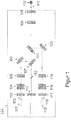
- FIG. 1 shows a first exemplary embodiment of a device with an array of optical elements.
- the device 122 has two laser light sources 101, 115.
- the laser light sources 101, 115 are suitable for generating laser light beams 102, 116 having different wavelengths.
- the generated laser light beams 102, 116 are guided on individual light paths, on which optical beam shaping devices 103, 117, for example lenses, optical isolators 104, 118 and bandpass filters 105, 119 are arranged.
- the light beams are deflected via mirrors 106, 120 to notch or notch filters 107, 121, wherein the notch or notch filters 107, 121 are arranged on a common light path, so that the light beams after deflection through the notch and notch filters 107, 121 cover a common light path.
- a further beam-shaping optical system 108 and a window 109 is arranged, wherein the further beam-shaping optical system 108 focuses the light beams onto a focal point and thus makes a sample 110, which is located in the focal point, accessible to a Raman analysis.
- Light 111 scattered back from the sample 110 is imaged through the window 109 and the further beam shaping optics 108 in the common light path.
- the scattered light then penetrates the notch filters 121, 107 in the opposite direction.
- the notch filters block the laser light and the elastically scattered portion of the scattered light.
- the Raman signals pass through the notch filters and encounter another beam-shaping optics 113.
- volume Bragg gratings may also be used.
- the notch or notch filters 107, 121 can also be replaced by volume Bragg gratings.
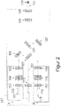
- FIG. 2 is another embodiment of in FIG. 1 shown embodiment shown.
- the laser sources 101, 115 are the associated optical beam shaping devices 103, 117, the associated optical isolators 104, 118 and the associated optical bandpass filters 105, 119 arranged in modules A, B, which are identical in mechanical structure to the laser wavelength of the laser light sources 101 and 115th
- the optode according to an embodiment of the invention is extended to a plurality of laser light sources.
- Modules A 1 to A n and B 1 to B n are arranged parallel to a parallel light deposit and suitable for emitting light of different wavelengths corresponding to parallel light paths spaced from the common light path.
- Mirrors M_A 1 to M_A n and M_B 1 to M_B n redirect the light beams at the parallel light paths to notch or notch filters F_A 1 to F_A n and F_B 1 to F_B n .
- the notch filters F_A 1 to F_A n and F_B 1 to F_B n are arranged on a common light path, which is arranged parallel to the individual light paths onto which the individual laser light beams were emitted. In this common light path, the light beams deflected by the notch filters are beamformed by a beam-shaping optical system O 1 and focused through a window W on a focusing point and a focusing region.
- a sample P located in the focus point or focus region scatters the excitation light through the window W and the beamforming optics O 1 (here O 1 now serves as collection optics) and the backscattered light passes the common light path in the reverse direction through the notch filters F_A 1 to F_A n and F_B 1 to F_B n back.
- the laser light and the elastically scattered light are blocked by the notch filters.
- the spectrally shifted Raman signals pass through the notch filters and are focused onto a fiber F by another beam shaping optics O 2 .
- the Raman signals coupled in here are transported via this fiber F to an evaluation unit.
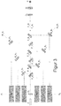
- FIGS. 4A to 4E show different constellations of sample positioning to the focal length of a common adjustable optic of an exemplary optode according to an embodiment of the invention.
- Figure 4A is shown as an excitation light 1 via an optical beam forming unit 02
- the beam forming unit 108 from the FIG. 1 corresponds, via a window 03, that of the window 109 FIG. 1 is focused on a focal point or a focus region with a distance a between the beam shaping unit 02 and window 03.
- a sample 04 which is located in the focal point or the focus region, scatters the excitation light 01 back as light 05.
- the light 05 is projected by the beam-shaping device 02 onto the optical beam-shaping device 07, that of the beam-shaping device 113 FIG. 1 equivalent.
- the beam shaping device 07 in turn focuses the light into a glass fiber 08.
- the FIG. 4B shows the analogous case to FIG. 4A
- sample 04 is no longer in the focus point, so that a maximum coupling of the Raman signal from the sample is no longer possible.
- FIG. 4C the out-of-focus positioning of the sample 04 occurs as a result of an intermediate layer of transparent or opaque material 09 arranged between the sample and the optode, which causes the focal point to be displaced.
- the Figures 5 and 6 show the transmission T of the 16 deflection devices of the preferred embodiment of the Fig. 3 depending on the absolute wave number ( Fig. 5 ) or the wavelength ( Fig. 6 ).
- Raman spectra in the range between 230 nm and 669 nm with the aid of 14 Excitation light sources can be measured.
- Raman spectra can thus be generated with the 14 excitation light sources and a suitable choice of the excitation wavelength can be made on the basis of the Raman spectra and properties of the sample.
- the central wavelengths of the excitation light sources are distributed uniformly over the spectrum with respect to the absolute wave number, ie are spaced equidistant from one another.
- wavenumber differences in the sense of the invention are then considered equal and thus the associated wavenumbers to be considered equidistant, if the wavenumber differences differ by less than 5% from each other.
- the distance is a minimum distance.
- the minimum distance may be about 10 cm -1 , 1000 cm -1 or 2000 cm -1 .
- the minimum distance guarantees a detection window between wave number adjacent excitation light sources, radiation inelastically scattered into the detection window can then be separated from elastically scattered radiation by means of the notch filters. With non-uniform distribution of the central wavelengths of the excitation light sources relative to the absolute wavenumber, observance of the minimum distance between adjacent excitation light source wavenumbers is also preferred.
- the distances between adjacent excitation light source wavenumbers are equal to the minimum distance or a multiple of the minimum distance.
- the width of the deflecting devices which are preferably designed as notch filters, is selected such that at least 99% of the elastically scattered radiation of the excitation light sources is deflected out of the collecting path.
- the width of the flanks of the 14 notch filters is kept as small as possible, so that between the notch filters a high transmission for the other wavelengths is provided, which correspond to the inelastic scattering of the light (Stokes range and anti-Stokes range).
Description
Die Erfindung betrifft eine Vorrichtung für die Raman-Spektroskopie mit einer Anordnung optischer Elemente mit Anregungslichtquellen. Insbesondere betrifft die Erfindung eine Vorrichtung mit einer Anordnung optischer Bauelemente mit Anregungslichtquellen mit unterschiedlichen Wellenlängen zur Anregung einer Probe in einer Weise, dass von der Probe in Folge der Anregung zurück gestreutes Licht einer Raman-spektroskopischen Analyse zugänglich wird.The invention relates to a device for Raman spectroscopy with an array of optical elements with excitation light sources. In particular, the invention relates to a device with an array of optical components with excitation light sources having different wavelengths for exciting a sample in such a way that light scattered back from the sample as a result of the excitation becomes accessible to Raman spectroscopic analysis.
Chemische, physikalische und biologische Proben lassen sich bekanntermaßen mittels Raman-Spektroskopie identifizieren und analysieren. Regt man eine Probe mit Licht, z.B. monochromatischem Laserlicht, an, so wird neben der Absorption und Emission ein geringer Teil des Lichts inelastisch gestreut. Die hieraus für jede Probe charakteristischen Signale werden Raman-Signale genannt. Sie sind zur Anregungswellenlänge sowohl langwellig (Stokes Bereich) als auch zu kürzeren Wellenlängen (Anti-Stokes Bereich) hin spektral verschoben. Auf Grund der bei Raumtemperatur typischer Weise höheren Intensität der Raman-Signale im Stokes Bereich wird dieser bevorzugt für die Identifikation und Analyse einer Probe genutzt.
Als Anregungswellenlänge in der Raman-Spektroskopie wird Laserlicht typischer Weise vom ultravioletten (UV) Spektralbereich, z.B. 260 nm bis zum Nah-Infraroten (NIR) Spektralbereich, z.B. 1500 nm, eingesetzt. Die Wahl der Anregungswellenlänge wird je nach Probeneigenschaft bzw. Art der Anwendung gewählt.
Der Wirkungsquerschnitt zur Erzeugung der Raman-Signale hängt proportional zu λ-4 von der Anregungswellenlänge λ ab. Eine Anregung bei kürzeren Wellenlängen kann demnach zu höheren Raman-Intensitäten führen.Chemical, physical and biological samples are known to be identified and analyzed by Raman spectroscopy. When a sample is excited with light, for example monochromatic laser light, a small portion of the light is scattered inelastically in addition to the absorption and emission. The signals characteristic of each sample are called Raman signals. They are spectrally shifted to the excitation wavelength both long-wave (Stokes area) and shorter wavelengths (anti-Stokes area). Due to the typically higher intensity of the Raman signals in the Stokes region at room temperature, this is preferably used for the identification and analysis of a sample.
As excitation wavelength in Raman spectroscopy, laser light is typically used from the ultraviolet (UV) spectral range, eg 260 nm, to the near-infrared (NIR) spectral range, eg 1500 nm. The choice of the excitation wavelength is chosen according to the sample property or type of application.
The cross section for generating the Raman signals is proportional to λ -4 of the excitation wavelength λ. Thus, excitation at shorter wavelengths can lead to higher Raman intensities.
Anregungen, insbesondere im ultravioletten und visuellen (VIS) Spektralbereich, können weiterhin bei bestimmten Proben zu Resonanzeffekten führen (Resonanz-Raman-Spektroskopie) und die schwachen Raman-Signale um mehrere Größenordnungen verstärken.In particular, excitations, especially in the ultraviolet and visual (VIS) spectral range, can lead to resonance effects in certain samples (resonance Raman spectroscopy) and amplify the weak Raman signals by several orders of magnitude.
Neben den Raman-Signalen können jedoch auch Fluoreszenzsignale entstehen. Diese überlagern typischer Weise die schwachen Raman-Signale und verhindern bzw. erschweren somit eine Raman-spektroskopische Analyse der Probe. Ist diese Eigenschaft der Probe im Vorfeld der Untersuchungen bekannt, lässt sich mit einer geeigneten Wahl der Anregungswellenlänge z.B. im NIR-Spektralbereich die gleichzeitige Anregung von Fluoreszenzsignalen vermeiden.However, besides the Raman signals, fluorescence signals can also be produced. These typically superimpose the weak Raman signals and thus prevent or complicate Raman spectroscopic analysis of the sample. If this property of the sample is known in advance of the investigations, with a suitable choice of the excitation wavelength, e.g. avoid simultaneous excitation of fluorescence signals in the NIR spectral range.
Die Wahl der Anregungswellenlänge bestimmt damit die Qualität der gemessenen Raman-Spektren. Insbesondere für unbekannte Proben sind somit Voruntersuchungen für eine geeignete Wahl der Anregungswellenlänge notwendig. Diese ist dann für das optische Messsystem weitgehend festgelegt.The choice of the excitation wavelength thus determines the quality of the measured Raman spectra. In particular for unknown samples preliminary investigations for a suitable choice of the excitation wavelength are therefore necessary. This is then largely determined for the optical measuring system.
Das optische Messsystem bzw. die Transferoptik, d.h. die Elemente zur Anregung von Proben und zur Sammlung von Raman-Signalen der Proben zu Spektralanalysezwecken, werden auch als Optoden bezeichnet.The optical measuring system or the transfer optics, i. the elements for excitation of samples and collection of Raman signals of the samples for spectral analysis purposes are also referred to as optodes.
Eine geeignete Optode führt das Anregungslicht zur Probe. Ein speziell auf die Anregungswellenlänge angepasster Bandpassfilter unterdrückt das von der Anregungsquelle emittierte Störlicht wie z.B. Plasmalinien bei Gaslasern bzw. verstärkter spontaner Emission (amplified spontaneous emission, ASE) bei Diodenlasern. Auch unerwünschte Signale von Quarzglasfasern, mit der das Anregungslicht zur Optode hin transportiert wurde, können so herausgefiltert werden. Diese Bandpassfilter besitzen eine nur schmale Transmissionskurve und sind zur Anregungswellenlänge ausgewählt.A suitable optode leads the excitation light to the sample. A bandpass filter specially adapted to the excitation wavelength suppresses the stray light emitted by the excitation source, e.g. Plasma lasers or amplified spontaneous emission (ASE) plasma lasers for diode lasers. Even unwanted signals from quartz glass fibers, with which the excitation light has been transported to the optode out, can be filtered out. These bandpass filters have only a narrow transmission curve and are selected at the excitation wavelength.
Im Sammelpfad wird das von der Probe zurück gestreute Licht eingesammelt und über eine geeignete Optik in ein System zur spektral selektiven Detektion abgebildet. Hierzu werden typischer Weise dispersive Elemente zur spektralen Trennung und Vielkanaldetektoren, z.B. CCDs, eingesetzt.In the collection path, the light scattered back from the sample is collected and imaged via suitable optics into a system for spectrally selective detection. For this For example, dispersive elements are used for spectral separation and multichannel detectors, eg CCDs.
Zwischen der Intensität eines Anregungslasers und der Intensität der erzeugten Raman-Signale liegen mehrere Größenordnungen. Eine Übersteuerung bzw. Sättigung von Pixeln einer CCD ist hier zu vermeiden, da überschüssige Ladungen in benachbarte Pixel übertragen werden ("Blooming" oder "Ausblühen") und es zu Artefaktbildung in den Raman-Spektren kommen kann. Die Raman-Signale müssen demzufolge im Sammelpfad spektral vom elastisch gestreuten Laserlicht getrennt werden, bevor sie den Detektor erreichen. Dies geschieht typischer Weise mit spektral selektiven Elementen wie z.B. Monochromatoren oder optischen Filtern. Für die Detektion von Stokes-Linien können Langpassfilter bzw. Notchfilter gewählt werden. Diese sind wie auch der im Anregungspfad befindliche Bandpassfilter an die Wellenlänge der Anregungslichtquelle und dem spektralen Inspektionsbereich angepasst.There are several orders of magnitude between the intensity of an excitation laser and the intensity of the generated Raman signals. Overshoot or saturation of pixels of a CCD is to be avoided here, since excess charges can be transferred to neighboring pixels ("blooming" or "blooming") and artifact formation in the Raman spectra can occur. The Raman signals must therefore be spectrally separated in the collection path from the elastically scattered laser light before they reach the detector. This is typically done with spectrally selective elements, e.g. Monochromators or optical filters. Longpass filters or notch filters can be selected for the detection of Stokes lines. As well as the bandpass filter in the excitation path, these are adapted to the wavelength of the excitation light source and the spectral inspection area.
Weitere optische Elemente wie Linsen, Spiegel, Filter und Glasfasern befinden sich innerhalb der Optode und sind typischer Weise zum Schutz von einem Gehäuse umgeben. Das Laserlicht bzw. die Raman-Signale gelangen über ein optisches Fenster zur Probe bzw. zurück in die Optode.Other optical elements such as lenses, mirrors, filters and glass fibers are located within the optode and are typically surrounded by a housing for protection. The laser light or the Raman signals pass through an optical window to the sample or back into the optode.
Die Untersuchung von unbekannten Substanzen, wie sie z.B. für sicherheitsspezifische Anwendungen an Flughäfen und Grenzstationen, für medizinische oder polizeiliche Anwendungen oder auch im privaten Bereich interessant ist, wird durch die einmalige Festlegung von Lichtquellen, Optiken und Filtersätzen deutlich erschwert. Dies gilt umso mehr für die der genannten Anwendungen zu favorisierenden portablen Geräte für vor Ort Messungen.The study of unknown substances, as e.g. For security-specific applications at airports and border stations, for medical or police applications or in the private sector is interesting, is made difficult by the unique determination of light sources, optics and filter sets. This applies all the more to the portable devices for on-site measurements which are to be favored for the named applications.
Bei herkömmlichen Anordnungen optischer Bauelemente zur Raman-Spektroskopie sind die optischen Elemente innerhalb einer Optode fest verbaut. Für einen Wechsel der Anregungswellenlänge müssen die Filter (Bandpassfilter und z.B. Langpassfilter) jedoch auf Grund ihrer spektralen Eigenschaften ersetzt werden. Ein Umbau der Optode ist somit notwendig.In conventional arrangements of optical components for Raman spectroscopy, the optical elements are permanently installed within an optode. However, for a change in the excitation wavelength, the filters (bandpass filters and, for example, long-pass filters) must be replaced on the basis of their spectral properties. A conversion of the optode is thus necessary.
Da die optischen Elemente innerhalb einer Optode an feste Positionen justiert und montiert sind, kann der Abstand zwischen einer Anregungs- bzw. Sammellinse und dem optischen Fenster einer Optode somit innerhalb eines Messsystems auch nicht variiert werden. Dieser Abstand bestimmt die Position des Laserfokus (bzw. des Sammelflecks) außerhalb der Optode. Bei festem Abstand können diese Positionen nicht an die optischen Eigenschaften einer z.B. transparenten oder trüben Probe angepasst werden. Auch hier ist ein aufwändiger Umbau der Optode notwendig.Since the optical elements within an optode are adjusted and mounted at fixed positions, the distance between an excitation lens and the optical window of an optode can thus not be varied within a measuring system. This distance determines the position of the laser focus (or collection spot) outside the optode. At a fixed distance, these positions can not match the optical properties of e.g. transparent or cloudy sample to be adjusted. Again, a complex conversion of the optode is necessary.
Eine multispektrale Beleuchtungsvorrichtung für Fluoreszenz-Untersuchungen ist in
Für den Bereich der acht Laser war ein Bandpassfilter kommerziell nicht verfügbar. Somit wurde zur Unterdrückung der ASE im Stokes-Bereich ein Kurzpassfilter eingesetzt. Ein Langpassfilter (F2 in
For the range of eight lasers, a bandpass filter was not commercially available. Thus, a short-pass filter was used to suppress the ASE in the Stokes region. A longpass filter (F2 in
Ebenfalls die Anwendung von SERDS adressiert das
Die Anpassung der Position des Anregungsfleckes beschreibt die Patentanmeldung
Die vorliegende Erfindung befasst sich mit der Aufgabe, eine Vorrichtung mit einer Anordnung optischer Bauelemente anzugeben, die es erlaubt, mehr als zwei Anregungslichtquellen mit spektral weit auseinander liegenden Wellenlängen zur Raman-spektroskopischen Analyse in tragbaren und/oder handlichen Geräten ohne jeglichen Justage- bzw. Montageaufwand zu realisieren. Darüber hinaus kann die Erfindung auch in SERDS-basierten Systemen Anwendung finden, ist aber nicht auf solche Anwendungen beschränkt.The present invention is concerned with the object to provide an apparatus with an array of optical components, which allows more than two excitation light sources with spectrally widely spaced wavelengths for Raman spectroscopic analysis in portable and / or handy devices without any adjustment or Installation effort to realize. Moreover, the invention can also find application in SERDS-based systems, but is not limited to such applications.
Die vorliegende Erfindung schlägt daher eine Vorrichtung für die Raman-Spektroskopie mit einer Anordnung optischer Bauelemente nach Anspruch 1 vor.
Die Vorrichtung umfasst Anregungslichtquellen für die Emission einzelner Lichtstrahlen mit unterschiedlichen Wellenlängen, deren spektraler Abstand in Wellenzahlen äquidistant zueinander ist. Der Abstand in Wellenzahlen ist vorzugsweise größer als das typische spektrale Fenster aller hinreichend notwendigen Raman-Signale zur Identifikation von unbekannten Stoffen. Das spektrale Fenster im Sinne der vorliegenden Erfindung ist derjenige spektrale Bereich, in dem interessierende Raman-Signale generiert werden können.
Ein besonderer Vorteil besteht darin, dass mit der erfindungsgemäßen Vorrichtung für unbekannte Proben ein Raman-Spektrum mit einer Vielzahl von Anregungslichtquellen über einen großen Spektralbereich erzeugt werden kann und somit für die Auswertung des Raman-Spektrums der ggf. unbekannten Proben eine günstige Wellenlänge verwendet werden kann. Insbesondere ist es vorteilhaft, dass keine bewegten optischen Elemente zur Umschaltung zwischen den Wellenlängen erforderlich sind.
Dies wird dadurch erreicht, dass die Vorrichtung eine Vielzahl von n>2 Anregungslichtquellen umfasst zur Emission von n Anregungsstrahlungen mit jeweils unterschiedlichen, in Wellenzahlen äquidistant von einander beabstandeten Emissionen, die jeweils entlang eines von n unterschiedlichen Lichtpfaden geführt sind; wobei jedem Lichtpfad eine Umlenkvorrichtung zugeordnet ist, die für eine jeweilige erste Wellenlänge der Anregungsstrahlung auf dem Lichtpfad ausgebildet ist, den jeweiligen Lichtpfad auf einen gemeinsamen Lichtpfad umzulenken, wobei der gemeinsame Lichtpfad eine Optik aufweist, die zur Fokussierung der Anregungsstrahlungen auf eine außerhalb der Vorrichtung angeordnete Probe ausgebildet ist. Mindestens n-1 der Umlenkvorrichtungen weisen jeweils eine erste Transmission für Wellenlängen aus einem Wellenlängenbereich, der um die jeweilige erste Wellenlänge liegt, und eine zweite Transmission für jeweilige andere Wellenlängen auf, wobei jeweils die erste Transmission kleiner als die zweite Transmission ist und wobei die Wellenlängenbereiche nicht überlappen.The present invention therefore proposes a device for Raman spectroscopy with an array of optical components according to
The device comprises excitation light sources for the emission of individual light beams with different wavelengths whose spectral distance in wavenumbers is equidistant from one another. The distance in wavenumbers is preferably larger than the typical spectral window of all sufficiently necessary Raman signals for the identification of unknown substances. The spectral window in the sense of the present invention is that spectral region in which Raman signals of interest can be generated.
A particular advantage is that with the inventive device for unknown samples a Raman spectrum can be generated with a large number of excitation light sources over a large spectral range and thus a favorable wavelength can be used for the evaluation of the Raman spectrum of the optionally unknown samples , In particular, it is advantageous that no moving optical elements for switching between the wavelengths are required.
This is achieved by the device comprising a large number of n> 2 excitation light sources for emission of n excitation radiations each having different equidistantly spaced wavenumbers, each guided along one of n different light paths; wherein each light path is associated with a deflection device, which is designed for a respective first wavelength of the excitation radiation on the light path, to redirect the respective light path to a common light path, wherein the common light path has an optical system which is arranged to focus the excitation radiation on an outside of the device Sample is formed. At least n-1 of the deflection devices each have a first transmission for wavelengths from a wavelength range that lies around the respective first wavelength, and a second transmission for respective other wavelengths, wherein each of the first transmission is smaller than the second transmission and wherein the wavelength ranges do not overlap.
Hierdurch kann über ein großes Wellenlängengebiet jeweils Anregungsstrahlung unterschiedlicher Wellenlängen auf die Probe fokussiert werden und die rückgestreute Strahlung (Raman-Signal) nachfolgend in einer Detektoreinheit (vorzugsweise Spektrometer mit CCD-Kamera) geleitet werden. Aufgrund der gewählten Transmissionen der Umlenkvorrichtung ist es möglich, die Anregungsstrahlung aus dem optischen Sammelpfad, der zur Detektoreinheit geleitet werden kann, wirksam zu eliminieren, jedoch die jeweils spektral nahe der Wellenlängen der Anregungsstrahlungen liegende Ramanstrahlung (besonders bevorzugt die Stokes-Banden) durch sämtliche Umlenkvorrichtungen hindurch entlang des optischen Sammelpfads passieren zu lassen. Da die n Anregungslichtquellen äquidistant voneinander beabstandet sind, kann das interessierende Spektrum für Anregungswellenlängen aus verschiedenen Spektralbereichen besonders effizient detektiert werden.In this way, in each case excitation radiation of different wavelengths can be focused onto the sample over a large wavelength range and the backscattered radiation (Raman signal) can subsequently be conducted in a detector unit (preferably spectrometer with CCD camera). Due to the selected transmissions of the deflection device, it is possible to effectively eliminate the excitation radiation from the optical collection path that can be conducted to the detector unit, but the Raman radiation spectrally near the wavelengths of the excitation radiation (most preferably the Stokes bands) through all deflection devices through along the optical collection path. Since the n excitation light sources are equidistant from each other, the spectrum of interest for excitation wavelengths from different spectral ranges can be detected particularly efficiently.
Vorzugsweise wird das an der Probe gestreute Raman-Signal von der Optik gesammelt und auf den gemeinsamen Lichtpfad in entgegengesetzter Richtung gelenkt.Preferably, the Raman signal scattered on the sample is collected by the optics and directed to the common light path in the opposite direction.
Vorzugsweise ist die Reflexion der mindestens n-1 Umlenkvorrichtungen für die jeweilige erste Wellenlänge größer als 0,5, bevorzugter größer als 0,6, noch bevorzugter größer als 0,7, noch bevorzugter größer als 0,8 und noch bevorzugter größer als 0,9.Preferably, the reflection of the at least n-1 deflection devices for the respective first wavelength is greater than 0.5, more preferably greater than 0.6, more preferably greater than 0.7, even more preferably greater than 0.8 and even more preferably greater than 0, 9th
Vorzugsweise ist jeweils ein Betrag einer Differenz zwischen Wellenlängen im Spektrum zueinander benachbarter Anregungsstrahlungen größer als eine Summe von Bandbreiten der jeweiligen zueinander benachbarten Anregungsstrahlungen. Als Bandbreite wird dasjenige Wellenlängenintervall um die jeweilige erste Wellenlänge (Zentralwellenlänge höchster Intensität) verstanden, in dem vorzugsweise 90%, bevorzugter 95%, noch bevorzugter 99% der Energie der Anregungsstrahlung liegen.Preferably, in each case an amount of a difference between wavelengths in the spectrum of mutually adjacent excitation radiation is greater than a sum of bandwidths of the respective adjacent excitation radiation. The bandwidth is understood to be the wavelength interval around the respective first wavelength (highest wavelength central wavelength) in which preferably 90%, more preferably 95%, even more preferably 99%, of the energy of the excitation radiation lies.
Vorzugsweise ist die Distanz in Wellenzahlen zwischen im Spektrum zueinander benachbarten Anregungsstrahlungen mindestens 10 cm-1, bevorzugter um mindestens 1000 cm-1 und noch bevorzugter um mindestens 2000 cm-1.Preferably, the distance in wavenumbers between excitation radiation adjacent to each other in the spectrum is at least 10 cm -1 , more preferably at least 1000 cm -1 and more preferably at least 2000 cm -1 .
Vorzugsweise weist auch die höchstens eine verbleibende Umlenkvorrichtung für Wellenlängen aus einem Wellenlängenbereich, der um eine erste Wellenlänge der Anregungsstrahlung auf dem der verbleibenden Umlenkvorrichtung zugeordneten Lichtpfad liegt, eine erste Transmission und eine zweite Transmission für jeweilige andere Wellenlängen auf, wobei die zweite Transmission der zweiten Umlenkvorrichtung größer als die erste Transmission der höchstens einen verbleibenden Umlenkvorrichtung ist.Preferably, the at least one remaining deflecting device for wavelengths from a wavelength range which lies around a first wavelength of the excitation radiation on the light path associated with the remaining deflecting device, also has a first transmission and a second transmission for respective other wavelengths, wherein the second transmission of the second deflecting device greater than the first transmission which is at most one remaining deflection device.
Vorzugsweise sind die erste Umlenkvorrichtung und/oder die zweite Umlenkvorrichtung als Notchfilter oder als Volumen Bragg Gitter ausgebildet.Preferably, the first deflecting device and / or the second deflecting device are designed as notch filters or as volume Bragg gratings.
Vorzugsweise ist die zweite Transmission der ersten Umlenkvorrichtung, die zweite Transmission der Umlenkvorrichtungen jeweils größer als 0,5, bevorzugter größer als 0,6, noch bevorzugter größer als 0,7, noch bevorzugter größer als 0,8 und noch bevorzugter größer als 0,9.Preferably, the second transmission of the first deflection device, the second transmission of the deflection devices is in each case greater than 0.5, more preferably greater than 0.6, more preferably greater than 0.7, even more preferably greater than 0.8 and even more preferably greater than 0, 9th
Durch die so gewählten Transmissionsverhältnisse wird gewährleistet, dass die elastisch an der Probe rückgestreute Strahlung mit Wellenlängen der jeweiligen Anregungslichtquellen durch die Umlenkvorrichtungen aus dem Sammelpfad gelenkt werden, wobei die inelastisch an der Probe rückgestreute Strahlung (egal welcher Anregungslichtquelle) sämtliche Umlenkvorrichtungen passieren und somit der Detektion zugänglich gemacht werden kann. Dadurch können Raman-Spektren unterschiedlicher Anregungswellenlängen (Anregungslichtquellen) gleichzeitig oder zeitlich sequentiell auf ein und denselben Detektor zur Untersuchung geleitet werden, ohne optische Elemente bewegen zu müssen.The transmission conditions selected in this way ensure that the radiation backscattered with wavelengths of the respective excitation light sources is deflected out of the collection path by the deflection devices, the radiation inelastically scattered back onto the sample (no matter which excitation light source) pass through all the deflection devices and thus the detection can be made accessible. As a result, Raman spectra of different excitation wavelengths (excitation light sources) can be simultaneously or temporally sequentially directed to one and the same detector for examination, without having to move optical elements.
Die Breite der Flanken niedriger Transmission der Umlenkvorrichtungen ist durch die jeweilige Bandbreite der Anregungslichtquellen nach unten begrenzt. Zwischen den Wellenlängen der jeweiligen Anregungslichtquellen soll ein ausreichender Abstand derart gewählt werden, dass innerhalb des gewählten spektralen Inspektionsbereichs entsprechende Raman-Signale nicht von einer Umlenkvorrichtung benachbarter Wellenlänge (bezogen auf Anregungslichtquelle) aus dem Sammelpfad herausgelenkt werden.The width of the flanks of low transmission of the deflection devices is limited by the respective bandwidth of the excitation light sources down. Between the wavelengths of the respective excitation light sources, a sufficient distance should be selected such that within the selected spectral inspection range corresponding Raman signals are not deflected out of the collection path by a deflection device of adjacent wavelength (relative to excitation light source).
In einer bevorzugten Ausführungsvariante wird die erfindungsgemäße Vorrichtung als Optode für eine Vorrichtung zur Detektion eines Raman-Spektrums verwendet. Besonders bevorzugt werden Raman-Spektren für jede der Anregungswellenlängen generiert und nachfolgend eine Auswahl einer bevorzugten Anregungswellenlängen getroffen, mit der dann die eigentliche Vermessung der Probe mittels mindestens eines Raman-Spektrums erfolgt.In a preferred embodiment, the device according to the invention is used as an optode for a device for detecting a Raman spectrum. Particularly preferably, Raman spectra are generated for each of the excitation wavelengths and subsequently a selection of a preferred excitation wavelengths is made, with which the actual measurement of the sample then takes place by means of at least one Raman spectrum.
Vorzugsweise ist n größer als 3, bevorzugter größer als 5, noch bevorzugter größer als 7 und noch bevorzugter größer als 9.Preferably, n is greater than 3, more preferably greater than 5, even more preferably greater than 7, and even more preferably greater than 9.
Diese Lichtquellen werden auf unterschiedlichen Lichtpfaden und zugeordneten Vorrichtungen zur Umlenkung der einzelnen Lichtstrahlen auf einen gemeinsamen Lichtpfad überlagert, wobei der gemeinsame Lichtpfad dieselbe Optik zur Fokussierung der Lichtstrahlen auf das Untersuchungsobjekt im Anregungspfad umfasst.These light sources are superimposed on different light paths and associated devices for deflecting the individual light beams onto a common light path, the common light path comprising the same optics for focusing the light beams onto the examination object in the excitation path.
Die einzelnen Lichtquellen werden dabei durch An- und Abschalten der jeweiligen Anregung adressiert. Durch Auswahl der geeigneten Anregungsquelle kann die bezogen auf die Raman-Signale optimale Wellenlänge ausgewählt werden. So können auch für unbekannte Stoffe mit einem Messsystem ohne Wechsel von Komponenten die für eine Analyse hinreichend notwendigen Signale erzeugt werden. Bevorzugt erfolgt die Auswahl der optimalen Wellenlänge derart, dass eine maximale Intensität des Raman-Signals oder ein maximales Signal-Rausch-Verhältnis vorliegt.The individual light sources are addressed by switching the respective excitation on and off. By selecting the appropriate excitation source, the optimum wavelength with respect to the Raman signals can be selected. Thus, even for unknown substances with a measuring system without changing components, the signals that are sufficiently necessary for an analysis can be generated. Preferably, the selection of the optimum wavelength is such that a maximum intensity of the Raman signal or a maximum signal-to-noise ratio is present.
Die Umschaltung zwischen den verschiedenen Wellenlängen der erfindungsgemäßen Vorrichtung erfolgt unter Verzicht auf mechanisch bewegliche Teile. Hierdurch wird eine besonders robuste und gleichzeitig kompakte Vorrichtung zur Verfügung gestellt. Insbesondere kann die erfindungsgemäße Vorrichtung justage- und montagefrei betrieben werden.The switching between the different wavelengths of the device according to the invention is done without mechanically moving parts. As a result, a particularly robust and at the same time compact device is provided. In particular, the device according to the invention can be operated without adjustment and assembly.
In einer anderen möglichen Ausführungsform werden die einzelnen Lichtstrahlen vor der Umlenkung durch Strahlformungsoptiken geformt und durch Bandpassfilter gefiltert.In another possible embodiment, the individual light beams are shaped prior to deflection by beamforming optics and filtered by bandpass filters.
In einer weiteren möglichen Ausführungsform sind auf den unterschiedlichen Lichtpfaden Strahlformungsoptiken und Bandpassfilter angeordnet.In another possible embodiment, beam shaping optics and bandpass filters are arranged on the different light paths.
Es ist ebenfalls möglich, auf dem gemeinsamen Lichtpfad eine Strahlformungsoptik so anzuordnen, dass jeder der einzelnen Lichtstrahlen einer Strahlformung unterworfen werden kann, ehe der einzelne Lichtstrahl auf die jeweilige Umlenkvorrichtung trifft.It is also possible to arrange a beam-shaping optical system on the common light path so that each of the individual light beams can be subjected to beam shaping before the individual light beam strikes the respective deflection device.
In einer besonders zur kompakten Bauweise geeigneten Ausführungsform sind die Anregungslichtquellen beidseitig einer weiterhin umfassten Sammeloptik mit einer Streulichtstrahlformungsoptik und einer Transferoptik angeordnet, wobei die Sammeloptik geeignet ist, von einem im Fokus befindlichen Objekt gestreutes Licht eines der einzelnen Lichtstrahlen über dieselbe Optik und über einen den gemeinsamen Lichtpfad umfassenden Sammellichtpfad zu sammeln und an einem Ausgang zur Verfügung zu stellen, und wobei die unterschiedlichen Lichtpfade parallel zu und zu dem gemeinsamen Lichtpfad beabstandet sind und Spiegel zur Umlenkung der einzelnen Lichtstrahlen auf die auf dem Sammellichtpfad angeordneten, auch Notchfilter genannte, Kerbfilter umfassen.In an embodiment which is particularly suitable for compact construction, the excitation light sources are arranged on both sides of a further comprising collection optics with scattered light beam shaping optics and transfer optics, the collection optics being suitable for one of the individual light beams scattered from an object in focus via the same optic and via the common one Light path comprising collecting light path and provide at an output, and wherein the different light paths are parallel to and spaced from the common light path and mirror for deflecting the individual light rays arranged on the collecting light path, also called notch filter, notch filters include.
Wird als Anregungslichtquelle ein Laser eingesetzt, der elektrisch auf zwei nah beieinander liegenden Wellenlängen emittiert, wie sie für SERDS benötigt werden, kann diese Möglichkeit der Trennung der Raman-Signale vom Fluoreszenzhintergrund ebenfalls für das Messsystem implementiert werden.If a laser is used as the excitation light source which emits electrically at two closely spaced wavelengths as required for SERDS, this possibility of separating the Raman signals from the fluorescence background can also be implemented for the measuring system.
Im Falle der Implementierung SERDS mittels einer elektrisch auf zwei nah beieinander liegenden Wellenlängen emittierenden Laserdiode wird diese zur alternierenden Erzeugung unterschiedlicher Anregungswellenlängen mittels des an die Laserdiode angelegten elektrischen Stroms alternierend mit zwei unterschiedlichen Anregungsbedingungen angesteuert, wobei das Hin- und Herschalten zwischen den Anregungsbedingungen vorzugsweise mit einer Frequenz größer als 0,1 Hz und vorzugsweise kleiner als 1 kHz erfolgt.
Die spektrale Analyse der vom zu untersuchenden Medium gestreuten elektromagnetischen Strahlung kann beispielsweise durch Einkoppeln der gestreuten Strahlung in einen Spektrographen erfolgen, wobei aus der gestreuten Strahlung für die unterschiedlichen Anregungswellenlängen jeweils mindestens ein Raman-Spektrum detektiert wird und aus den mindestens zwei detektierten Raman-Spektren unterschiedlicher Anregungswellenlängen ein Raman-Spektrum des zu untersuchenden Mediums ermittelt wird, in dem der Fluoreszenzuntergrund rechnerisch eliminiert ist. Dabei ist es bevorzugt, die Detektion der einzelnen Raman-Spektren unterschiedlicher Anregungswellenlängen mit der alternierenden Ansteuerung der Laserdiode zu synchronisieren. Dabei kann die Detektion eines Raman-Spektrums jeweils innerhalb eines Zeitintervalls erfolgen, in dem die Stromstärke des an die Laserdiode angelegten Stroms konstant gehalten wird.
Die Unterdrückung des Fluoreszenzhintergrunds ist besonders dann effizient möglich, wenn die Anregungslichtquellen Laserdioden sind, die jeweils zur Erzeugung von Anregungsstrahlung mindestens zweier unterschiedlicher Wellenlängen mit mindestens zwei unterschiedlichen Anregungsbedingungen ansteuerbar sind.
In einer möglichen Ausführungsform wird zusätzlich im Anregungspfad die Optik, die die Fokussierung auf das Messobjekt realisiert, auf einen beweglichen Halter montiert, der z.B. elektromechanisch stufenlos, ohne Austausch der Optik an den zur Messung benötigten Fokuspunktes oder einer Fokusregion angepasst wird.
Dies erlaubt die individuelle Anpassung der Position des Fokusses außerhalb der Optode an die Position der zu untersuchenden Probe und deren Eigenschaften für eine optimale Sammlung generierter Raman-Signale. Darüber hinaus erlaubt es die Ausblendung von Signalen außerhalb des Fokus und die verbesserte Detektion von spektroskopischen Signalen bei optisch trüben oder transparenten Proben oder Proben in Verpackungen.In the case of implementing SERDS by means of a laser diode emitting electrically at two closely spaced wavelengths, it is driven alternately with two different excitation conditions for alternately generating different excitation wavelengths by means of the electric current applied to the laser diode, the switching back and forth between the two Excitation conditions preferably with a frequency greater than 0.1 Hz and preferably less than 1 kHz.
The spectral analysis of the scattered by the medium to be examined electromagnetic radiation can for example be done by coupling the scattered radiation in a spectrograph, wherein from the scattered radiation for the different excitation wavelengths in each case at least one Raman spectrum is detected and from the at least two detected Raman spectra different Excitation wavelengths a Raman spectrum of the medium to be examined is determined, in which the fluorescence background is mathematically eliminated. It is preferred to synchronize the detection of the individual Raman spectra of different excitation wavelengths with the alternating drive of the laser diode. In this case, the detection of a Raman spectrum can each take place within a time interval in which the current intensity of the current applied to the laser diode is kept constant.
The suppression of the fluorescence background is possible in an efficient manner, in particular, when the excitation light sources are laser diodes which can each be driven to generate excitation radiation of at least two different wavelengths with at least two different excitation conditions.
In one possible embodiment, the optics, which realizes focusing on the measurement object, are additionally mounted in the excitation path on a movable holder, which is adapted, for example, electromechanically steplessly, without replacement of the optics, to the focus point required for the measurement or to a focus region.
This allows the individual adaptation of the position of the focus outside the optode to the position of the sample to be examined and its properties for an optimal collection of generated Raman signals. In addition, it allows the suppression of out-of-focus signals and the improved detection of spectroscopic signals in optically opaque or transparent samples or samples in packaging.
Gemäß einem weiteren Ausführungsbeispiel der vorliegenden Erfindung wird eine Vorrichtung zur Detektion eines Raman-Spektrums eines zu untersuchenden Mediums offenbart, welche die erfindungsgemäße Vorrichtung als Optode verwendet. Dabei umfasst die Optode Mittel zur Einkopplung der emittierten Anregungsstrahlung in das zu untersuchende Medium. Weiterhin umfasst die Optode Mittel zur Einkopplung der vom zu untersuchenden Medium gestreuten Strahlung in ein spektral-optisches System, wobei ein Datenverarbeitungsgerät vorgesehen ist, das mit dem spektral-optischen System verbunden ist. Das Datenverarbeitungsgerät ist ausgebildet, aus den mindestens zwei mittels des spektral-optischen Systems detektierten Spektren unterschiedlicher Anregungswellenlängen ein Raman-Spektrum des zu untersuchenden Mediums zu berechnen, in dem der Fluoreszenzuntergrund rechnerisch separiert wird. Vorzugsweise ist das spektral-optische System durch einen Spektrographen mit Vielkanaldetektor z.B. CCD-Zeile ausgebildet.According to another embodiment of the present invention, an apparatus for the Detection of a Raman spectrum of a medium to be examined, which uses the device according to the invention as an optode. In this case, the optode comprises means for coupling the emitted excitation radiation into the medium to be examined. Furthermore, the optode comprises means for coupling the radiation scattered by the medium to be examined into a spectral-optical system, wherein a data processing device is provided which is connected to the spectral-optical system. The data processing device is designed to calculate from the at least two spectra of different excitation wavelengths detected by the spectral optical system a Raman spectrum of the medium to be examined, in which the background fluorescence is computationally separated. Preferably, the spectral optical system is formed by a spectrograph with a multi-channel detector, for example a CCD line.
Es ist besonders bevorzugt, dass die die Laserdiode zur Erzeugung unterschiedlicher Anregungswellenlängen mit einer von einem Modulator modulierten Stromquelle verbunden ist, und der Modulator die Stromquelle alternierend moduliert. Vorzugsweise erfolgt das Hin- und Herschalten mit einer Frequenz größer als 0,1 Hz. Vorzugsweise ist die Vorrichtung mit einem spektral-optischen System gekoppelt. Vorzugsweise ist ein Datenverarbeitungsgerät mit dem Modulator verbunden. Vorzugsweise ist die Detektion von Raman-Spektren unterschiedlicher Anregungswellenlängen mit der alternierenden Ansteuerung der Laserdiode synchronisiert.It is particularly preferred that the laser diode is connected to a modulated by a modulator current source for generating different excitation wavelengths, and the modulator modulates the current source alternately. Preferably, the switching back and forth takes place at a frequency greater than 0.1 Hz. Preferably, the device is coupled to a spectral-optical system. Preferably, a data processing device is connected to the modulator. Preferably, the detection of Raman spectra of different excitation wavelengths is synchronized with the alternate driving of the laser diode.
Es ist weiterhin bevorzugt, dass die auf dem gemeinsamen Lichtpfad angeordnete Optik zur Fokussierung der Anregungsstrahlung auf eine Probe ansteuerbar und ein Abstand der Optik von einem Fenster (bzw. einer äußeren Facette der Vorrichtung über welche die Anregungsstrahlung austritt) und damit die Position des Fokuspunktes oder einer Fokusregion außerhalb der Vorrichtung durch Ansteuerung der Optik einstellbar ist. Dadurch wird es vorteilhafterweise möglich, die Strahlformung innerhalb der Optode an die optischen Eigenschaften einer z.B. transparenten oder trüben Probe in einfacher Weise anzupassen. In einer besonders bevorzugten Ausführungsvariante wird die erfindungsgemäße Vorrichtung als Optode für eine Vorrichtung zur Detektion eines Raman-Spektrums verwendet, wobei Raman-Spektren für jede der Anregungswellenlängen und jeweils für unterschiedliche Fokustiefen generiert und nachfolgend eine Auswahl einer bevorzugten Anregungswellenlänge und einer bevorzugten Fokustiefe getroffen wird, mit denen dann die eigentliche Vermessung der Probe mittels mindestens eines Raman-Spektrums erfolgt.It is furthermore preferred for the optics arranged on the common light path to be able to focus the excitation radiation on a sample and for the optics to be separated from a window (or an outer facet of the device via which the excitation radiation emerges) and thus the position of the focal point or a focus region outside the device by controlling the optics is adjustable. This advantageously makes it possible to adapt the beam shaping within the optode to the optical properties of, for example, a transparent or turbid sample in a simple manner. In a particularly preferred embodiment, the device according to the invention is used as an optode for a device for detecting a Raman spectrum, wherein Raman spectra for each of the Excitation wavelengths and generated in each case for different focus depths and then a selection of a preferred excitation wavelength and a preferred focus depth is made, with which then the actual measurement of the sample by means of at least one Raman spectrum.
Beispielhafte Optoden und Ausführungsbeispiele der Erfindung werden anhand der Zeichnungen und der nachfolgenden Beschreibung näher erläutert.
Figur 1- zeigt eine erste beispielhafte Optode,
Figur 2- zeigt eine zweite beispielhafte Optode
Figur 3- zeigt eine dritte beispielhafte Optode, in der die vorliegende Erfindung realisiert ist,
- Figuren 4A-4E
- zeigen unterschiedliche Konstellationen von Probenpositionierungen zu Brennweite einer gemeinsamen Optik einer beispielhaften Optode nach einer Ausführungsform der Erfindung,
Figur 5- zeigt die Transmission der Vielzahl von Umlenkvorrichtungen der Ausführungsvariante der
Fig. 3 in Abhängigkeit der Wellenzahl, und Figur 6- zeigt die Transmission der Vielzahl von Umlenkvorrichtungen der Ausführungsvariante der
Fig. 3 in Abhängigkeit der Wellenlänge.
- FIG. 1
- shows a first exemplary optode,
- FIG. 2
- shows a second exemplary optode
- FIG. 3
- shows a third exemplary optode in which the present invention is realized,
- Figures 4A-4E
- show different constellations of sample positions to focal length of a common optic of an exemplary optode according to an embodiment of the invention,
- FIG. 5
- shows the transmission of the plurality of deflection devices of the embodiment of the
Fig. 3 depending on the wave number, and - FIG. 6
- shows the transmission of the plurality of deflection devices of the embodiment of the
Fig. 3 depending on the wavelength.
Die hier beispielhaft vorgestellte Vorrichtung mit einer Anordnung optischer Elemente zeigt ein neuartiges Konzept einer Optode für die Raman-Spektroskopie mit der Möglichkeit eines Wechsels der Anregungswellenlänge über einen weiten Spektralbereich z.B. vom NIR (785 nm) zum UV (266 nm) und einer einstellbaren Position des Laserfokus bzw. Sammelfleck ohne Austausch der Optiken. Dabei erfolgt der Wechsel der Anregungswellenlänge und der dazu gehörigen Sammelpfade ohne bewegliche Teile.
Die Lichtstrahlen werden über Spiegel 106, 120 auf Notch- bzw. Kerbfilter 107, 121 umgelenkt, wobei die Kerb- oder Notchfilter 107, 121 auf einem gemeinsamen Lichtpfad angeordnet sind, so dass die Lichtstrahlen nach Umlenken durch den Notch- und Kerbfilter 107, 121 einen gemeinsamen Lichtweg zurücklegen. Auf diesem gemeinsamen Lichtweg ist eine weitere Strahlformungsoptik 108 und ein Fenster 109 angeordnet, wobei die weitere Strahlformungsoptik 108 die Lichtstrahlen auf einen Fokuspunkt fokussiert und somit eine Probe 110, die sich im Fokuspunkt befindet, einer Ramananalyse zugänglich macht. Von der Probe 110 zurück gestreutes Licht 111 wird durch das Fenster 109 und die weitere Strahlformungsoptik 108 auf dem gemeinsamen Lichtweg abgebildet. Dann durchdringt das Streulicht die Notchfilter 121, 107 in entgegen gesetzter Richtung. Die Notchfilter blocken das Laserlicht und den elastisch gestreuten Anteil des Streulichts. Die Raman-Signale passieren die Notchfilter und treffen auf eine weitere Strahlformungsoptik 113. Diese fokussiert und koppelt die Raman-Photonen in eine Transferoptik, beispielsweise eine Glasfaser, die die Raman-Signale zu einer Analyseeinheit z.B. einem Spektrometer inklusive einem Vielkanaldetektor, etwa eine CCD, transportiert.
Anstelle der Spiegel 106, 120 können auch Volumen Bragg-Gitter verwendet werden. Zusätzlich oder alternativ lassen sich auch die Notch- bzw. Kerbfilter 107, 121 durch Volumen Bragg-Gitter ersetzen.The device presented here by way of example with an arrangement of optical elements shows a novel concept of an optode for Raman spectroscopy with the possibility of changing the excitation wavelength over a wide spectral range, for example from NIR (785 nm) to UV (266 nm) and an adjustable position of the Laser focus or accumulation spot without replacement of the optics. In this case, the change of the excitation wavelength and the associated collection paths takes place without moving parts.
The light beams are deflected via
Instead of the
In
In
In
Die
Claims (12)
- Apparatus for Raman spectroscopy with an arrangement of optical elements, comprising:a plurality of n>2 excitation light sources (A1 to An and B1 to Bn) for emitting n excitation radiations with respectively different emissions equally spaced from each other in wavenumbers which are guided along one of a plurality of n different light paths, respectively;wherein a deflection device (F_A1 to F_An and F_B1 to F_Bn) is associated with every light path, which deflection device is formed on the associated light path for a respective first wavelength of the excitation radiation in order to deflect the respective light path onto a common light path,wherein the common light path comprises an optical system (O1) which is adapted to focus the excitation radiations,wherein at least n-1 of the deflection devices (F_A1 to F_An and F_B1 to F_Bn) comprise, respectively, a first transmission for wavelengths of one respective wavelength range around the respective first wavelength, and a second transmission for respective other wavelengths, wherein the first transmission is smaller than the second transmission, respectively, and wherein the wavelength ranges do not overlap.
- Apparatus according to claim 1, wherein, respectively, an amount of a difference between wavelengths in the spectrum of excitation radiations adjacent to each other is greater than a sum of band widths of the respective excitation radiations adjacent to each other.
- Apparatus according to one of the preceding claims, wherein the distance in wavenumbers between excitation radiations adjacent to each other in the spectrum is at least 10 cm-1.
- Apparatus according to one of the preceding claims, wherein the at most one remaining deflection device, too, comprises for wavelengths of a wavelength range around an associated first wavelength of the excitation radiation on the light path associated with the remaining deflection device, and a second transmission for associated other wavelengths, wherein the first transmission is smaller than the second transmission of the at most one remaining deflection device.
- Apparatus according to one of the preceding claims, wherein the at least n-1 deflection devices (F_A1 to F_An and F_B1 to F_Bn) are formed as notch filters or volume Bragg gratings.
- Apparatus according to one of the preceding claims, wherein the first transmission of the at least n-1 deflection devices (F_A1 to F_An and F_B1 to F_Bn) is, respectively, smaller than 0.5.
- Apparatus according to one of the preceding claims, wherein the second transmission of the at least n-1 deflection devices (F_A1 to F_An and F_B1 to F_Bn) is greater than 0.5.
- Apparatus according to one of the preceding claims, wherein n is greater than 3.
- Apparatus according to one of the preceding claims, wherein the apparatus comprises a window (W), and wherein the optical system (O1) can be driven and a distance of the optical system (O1) can be adjusted from the window (W) and thus the position of the focal point or a focal region can be adjusted outside the apparatus by driving the optical system (O1).
- Apparatus according to one of the preceding claims, wherein beam shaping optical systems and/or band-pass filters are arranged on the different light paths.
- Apparatus according to claim 9, wherein the excitation light sources (A1 to An and B1 to Bn) are arranged on both sides of a further comprised optical collection system with an optical system (O2) for shaping a scattered light beam and a transfer optical system (F) confocally arranged with respect to the optical system (O1), wherein the optical collection system is adapted to collect light of one of the individual light beams scattered by an object (P) in the focus by the window (W) and by the optical system (O1) and by a collection light path comprising the common light path, and to provide it at an output.
- Apparatus according to one of the preceding claims, wherein the excitation light sources (A1 to An and B1 to Bn) are laser diodes which, respectively, can be driven under at least two different excitation conditions in order to generate excitation radiation of at least two different wavelengths
Applications Claiming Priority (2)
| Application Number | Priority Date | Filing Date | Title |
|---|---|---|---|
| DE102012216164.3A DE102012216164B4 (en) | 2012-09-12 | 2012-09-12 | Device with an arrangement of optical elements |
| PCT/EP2013/068938 WO2014041089A1 (en) | 2012-09-12 | 2013-09-12 | Device having an arrangement of optical elements |
Publications (2)
| Publication Number | Publication Date |
|---|---|
| EP2895844A1 EP2895844A1 (en) | 2015-07-22 |
| EP2895844B1 true EP2895844B1 (en) | 2018-11-07 |
Family
ID=49328500
Family Applications (1)
| Application Number | Title | Priority Date | Filing Date |
|---|---|---|---|
| EP13774619.4A Active EP2895844B1 (en) | 2012-09-12 | 2013-09-12 | Apparatus with an arrangement of optical elements |
Country Status (6)
| Country | Link |
|---|---|
| US (1) | US9563061B2 (en) |
| EP (1) | EP2895844B1 (en) |
| JP (1) | JP6255022B2 (en) |
| DE (1) | DE102012216164B4 (en) |
| DK (1) | DK2895844T3 (en) |
| WO (1) | WO2014041089A1 (en) |
Families Citing this family (7)
| Publication number | Priority date | Publication date | Assignee | Title |
|---|---|---|---|---|
| US10746600B2 (en) * | 2015-01-09 | 2020-08-18 | California Institute Of Technology | Dual wavelength context imaging Raman and fluorescence spectrometer |
| RU2629703C1 (en) * | 2016-05-16 | 2017-08-31 | Федеральное государственное бюджетное учреждение науки Институт электрофизики Уральского отделения Российской академии наук (ИЭФ УрО РАН) | Luminescent method of determining quantitative content of inhomogeneously distributed additional crystal phase in strongly scattering dispersive two-phase media with impurity ions-luminogens |
| DE102016111747B4 (en) * | 2016-06-27 | 2020-10-01 | Forschungsverbund Berlin E.V. | Method and device for Raman spectroscopy |
| KR20180051196A (en) * | 2016-11-08 | 2018-05-16 | 삼성전자주식회사 | Spectrometer, apparatus and method for measuring bio-information |
| EP3601968A4 (en) * | 2017-03-30 | 2020-12-16 | Agency for Science, Technology and Research | Optical probe, raman spectroscopy system, and method of using the same |
| JP7246466B2 (en) | 2018-08-06 | 2023-03-27 | サーモ エレクトロン サイエンティフィック インストルメンツ リミテッド ライアビリティ カンパニー | Monochromator with stray light reduction |
| CN109580587A (en) * | 2019-02-01 | 2019-04-05 | 浙江澍源智能技术有限公司 | A kind of difference Raman spectrometer that can deduct fluorescence in real time and its method |
Family Cites Families (18)
| Publication number | Priority date | Publication date | Assignee | Title |
|---|---|---|---|---|
| CA2048564C (en) | 1990-08-16 | 2001-10-23 | Paul Graham Coombs | Optically variable interference device with peak suppression and method |
| DE19956620A1 (en) * | 1999-11-25 | 2001-05-31 | Zeiss Carl Jena Gmbh | Detecting fluorescence events in microscope, involves exposing specimen to light from modulated and/or pulsed laser source, detecting fluorescence at two or more detector phase angles |
| EP1316794A1 (en) * | 2001-11-28 | 2003-06-04 | Cambridge University Technical Services Limited | A dual wavelength optical fluorescence analyser |
| US6897951B2 (en) * | 2003-02-14 | 2005-05-24 | Raman Systems, Inc. | Probe assemblies for Raman spectroscopy |
| WO2005038419A2 (en) * | 2003-10-17 | 2005-04-28 | Intel Corporation | A method and device for detecting small numbers of molecules using surface-enhanced coherent anti-stokes raman spectroscopy |
| US7245369B2 (en) | 2003-11-13 | 2007-07-17 | B & W Tek, Inc. | Spectroscopic apparatus using spectrum narrowed and stabilized laser with Bragg grating |
| US7102746B2 (en) * | 2003-12-16 | 2006-09-05 | New Chromex, Inc. | Raman spectroscope |
| US8105849B2 (en) * | 2004-02-27 | 2012-01-31 | Board Of Regents, The University Of Texas System | Integration of fluids and reagents into self-contained cartridges containing sensor elements |
| DE102004034977A1 (en) * | 2004-07-16 | 2006-02-02 | Carl Zeiss Jena Gmbh | Scanning microscope and use |
| DE102004034998A1 (en) * | 2004-07-16 | 2006-02-02 | Carl Zeiss Jena Gmbh | Laser scanning microscope, comprises laser module and beam splitter provided on two lighting channels for variable distribution of laser light and two lasers combined in path of rays, in which splitter is arranged for distribution of light |
| DE102005054184B4 (en) * | 2005-11-14 | 2020-10-29 | Carl Zeiss Microscopy Gmbh | Multispectral lighting device and measuring method |
| DE102006048054A1 (en) * | 2006-10-11 | 2008-04-17 | Carl Zeiss Microimaging Gmbh | Multispectral illumination device |
| US7982869B2 (en) * | 2006-10-24 | 2011-07-19 | Pd-Ld Inc. | Compact, low cost Raman monitor for single substances |
| JP2010160043A (en) * | 2009-01-08 | 2010-07-22 | Panasonic Corp | Surface intensifying raman spectrophotometric method, and surface intensifying raman spectrophotometric apparatus using the same |
| JP5307629B2 (en) * | 2009-05-22 | 2013-10-02 | オリンパス株式会社 | Scanning microscope equipment |
| DE102009031231A1 (en) * | 2009-06-26 | 2010-12-30 | Carl Zeiss Microlmaging Gmbh | Methods and arrangements for fluorescence microscopy |
| JP5543760B2 (en) * | 2009-11-24 | 2014-07-09 | オリンパス株式会社 | Light source device, microscope system, and laser beam multiplexing method |
| US20120099102A1 (en) | 2010-10-26 | 2012-04-26 | Bello Job M | Dual and multi-wavelength sampling probe for raman spectroscopy |
-
2012
- 2012-09-12 DE DE102012216164.3A patent/DE102012216164B4/en not_active Expired - Fee Related
-
2013
- 2013-09-12 US US14/427,437 patent/US9563061B2/en active Active
- 2013-09-12 EP EP13774619.4A patent/EP2895844B1/en active Active
- 2013-09-12 JP JP2015531562A patent/JP6255022B2/en active Active
- 2013-09-12 DK DK13774619.4T patent/DK2895844T3/en active
- 2013-09-12 WO PCT/EP2013/068938 patent/WO2014041089A1/en active Application Filing
Non-Patent Citations (1)
| Title |
|---|
| None * |
Also Published As
| Publication number | Publication date |
|---|---|
| DE102012216164B4 (en) | 2016-04-28 |
| JP6255022B2 (en) | 2017-12-27 |
| JP2015531874A (en) | 2015-11-05 |
| DK2895844T3 (en) | 2019-03-04 |
| US9563061B2 (en) | 2017-02-07 |
| DE102012216164A1 (en) | 2014-03-13 |
| WO2014041089A1 (en) | 2014-03-20 |
| EP2895844A1 (en) | 2015-07-22 |
| US20150219906A1 (en) | 2015-08-06 |
Similar Documents
| Publication | Publication Date | Title |
|---|---|---|
| EP2895844B1 (en) | Apparatus with an arrangement of optical elements | |
| EP2156154B1 (en) | Spectrometer comprising solid body sensors and secondary electron multipliers | |
| EP1754032B1 (en) | Echelle spectrometer with improved use of the detector by means of two spectrometer arrangements | |
| EP1891408B1 (en) | Method and device for producing and detecting a raman spectrum | |
| EP3309538B1 (en) | Optical system and method for spectroscopy | |
| DE102010045856A1 (en) | Optical imaging system for multispectral imaging | |
| DE102007039845A1 (en) | Monochromator system, for optical spectrometers, has detectors that detect received portions of light scattered from specific region of sample surface in response to receive light of respective excitation wavelengths | |
| EP3465165B1 (en) | Method and device for raman spectroscopy | |
| WO2016096133A1 (en) | Device and method for verifying feature substances | |
| DE102012007045B4 (en) | Apparatus and method for microscopy | |
| EP3217205A1 (en) | Device and method for multispot scanning microscopy | |
| EP2282194A1 (en) | Apparatus for carrying out real-time PCR reactions | |
| DE102015001032A1 (en) | Raman spectroscopy illumination and readout system | |
| DE102017130772A1 (en) | Spectrometer arrangement, method for generating a two-dimensional spectrum by means of such | |
| DE4413096B4 (en) | Multi-element atomic absorption spectrometer and measuring method using such an atomic absorption spectrometer | |
| DE102005024271B4 (en) | Grating spectrometer system and method for measured value acquisition | |
| EP3660474B1 (en) | Apparatus and method for raman spectroscopy | |
| DE10155142A1 (en) | Dark-field imaging device for spatially resolved dark-field imaging of a flat sample | |
| DE102020131374B4 (en) | Fluorescence detection | |
| DE202013002752U1 (en) | Device for detecting fluorescence properties of samples | |
| DE10310645B3 (en) | Optical spectrometer for recording optical spectra, especially visible, ultraviolet and/or infrared, feeds fraction of beam transmitted through photonic crystal to absorber or out of spectrometer | |
| DE102016110210B4 (en) | spectrometer | |
| DE102010041748A1 (en) | Device for spectroscopic measurement of e.g. glass plate for scattered light measurements, has two crossbars moving measuring unit parallel to direction of sample, and third crossbar moving measuring unit transverse to direction |
Legal Events
| Date | Code | Title | Description |
|---|---|---|---|
| PUAI | Public reference made under article 153(3) epc to a published international application that has entered the european phase |
Free format text: ORIGINAL CODE: 0009012 |
|
| 17P | Request for examination filed |
Effective date: 20150410 |
|
| AK | Designated contracting states |
Kind code of ref document: A1 Designated state(s): AL AT BE BG CH CY CZ DE DK EE ES FI FR GB GR HR HU IE IS IT LI LT LU LV MC MK MT NL NO PL PT RO RS SE SI SK SM TR |
|
| AX | Request for extension of the european patent |
Extension state: BA ME |
|
| DAX | Request for extension of the european patent (deleted) | ||
| GRAP | Despatch of communication of intention to grant a patent |
Free format text: ORIGINAL CODE: EPIDOSNIGR1 |
|
| STAA | Information on the status of an ep patent application or granted ep patent |
Free format text: STATUS: GRANT OF PATENT IS INTENDED |
|
| RIC1 | Information provided on ipc code assigned before grant |
Ipc: G02B 27/14 20060101ALI20180525BHEP Ipc: G01N 21/39 20060101ALN20180525BHEP Ipc: G01J 3/44 20060101ALI20180525BHEP Ipc: G01J 3/427 20060101ALI20180525BHEP Ipc: G01N 21/65 20060101AFI20180525BHEP |
|
| INTG | Intention to grant announced |
Effective date: 20180618 |
|
| GRAS | Grant fee paid |
Free format text: ORIGINAL CODE: EPIDOSNIGR3 |
|
| GRAA | (expected) grant |
Free format text: ORIGINAL CODE: 0009210 |
|
| STAA | Information on the status of an ep patent application or granted ep patent |
Free format text: STATUS: THE PATENT HAS BEEN GRANTED |
|
| AK | Designated contracting states |
Kind code of ref document: B1 Designated state(s): AL AT BE BG CH CY CZ DE DK EE ES FI FR GB GR HR HU IE IS IT LI LT LU LV MC MK MT NL NO PL PT RO RS SE SI SK SM TR |
|
| REG | Reference to a national code |
Ref country code: GB Ref legal event code: FG4D Free format text: NOT ENGLISH |
|
| REG | Reference to a national code |
Ref country code: CH Ref legal event code: EP Ref country code: AT Ref legal event code: REF Ref document number: 1062661 Country of ref document: AT Kind code of ref document: T Effective date: 20181115 |
|
| REG | Reference to a national code |
Ref country code: IE Ref legal event code: FG4D Free format text: LANGUAGE OF EP DOCUMENT: GERMAN |
|
| REG | Reference to a national code |
Ref country code: DE Ref legal event code: R096 Ref document number: 502013011560 Country of ref document: DE |
|
| REG | Reference to a national code |
Ref country code: CH Ref legal event code: NV Representative=s name: HEPP WENGER RYFFEL AG, CH |
|
| REG | Reference to a national code |
Ref country code: DK Ref legal event code: T3 Effective date: 20190225 |
|
| REG | Reference to a national code |
Ref country code: NL Ref legal event code: MP Effective date: 20181107 |
|
| REG | Reference to a national code |
Ref country code: LT Ref legal event code: MG4D |
|
| PG25 | Lapsed in a contracting state [announced via postgrant information from national office to epo] |
Ref country code: IS Free format text: LAPSE BECAUSE OF FAILURE TO SUBMIT A TRANSLATION OF THE DESCRIPTION OR TO PAY THE FEE WITHIN THE PRESCRIBED TIME-LIMIT Effective date: 20190307 Ref country code: ES Free format text: LAPSE BECAUSE OF FAILURE TO SUBMIT A TRANSLATION OF THE DESCRIPTION OR TO PAY THE FEE WITHIN THE PRESCRIBED TIME-LIMIT Effective date: 20181107 Ref country code: BG Free format text: LAPSE BECAUSE OF FAILURE TO SUBMIT A TRANSLATION OF THE DESCRIPTION OR TO PAY THE FEE WITHIN THE PRESCRIBED TIME-LIMIT Effective date: 20190207 Ref country code: NO Free format text: LAPSE BECAUSE OF FAILURE TO SUBMIT A TRANSLATION OF THE DESCRIPTION OR TO PAY THE FEE WITHIN THE PRESCRIBED TIME-LIMIT Effective date: 20190207 Ref country code: LT Free format text: LAPSE BECAUSE OF FAILURE TO SUBMIT A TRANSLATION OF THE DESCRIPTION OR TO PAY THE FEE WITHIN THE PRESCRIBED TIME-LIMIT Effective date: 20181107 Ref country code: HR Free format text: LAPSE BECAUSE OF FAILURE TO SUBMIT A TRANSLATION OF THE DESCRIPTION OR TO PAY THE FEE WITHIN THE PRESCRIBED TIME-LIMIT Effective date: 20181107 Ref country code: LV Free format text: LAPSE BECAUSE OF FAILURE TO SUBMIT A TRANSLATION OF THE DESCRIPTION OR TO PAY THE FEE WITHIN THE PRESCRIBED TIME-LIMIT Effective date: 20181107 |
|
| PG25 | Lapsed in a contracting state [announced via postgrant information from national office to epo] |
Ref country code: NL Free format text: LAPSE BECAUSE OF FAILURE TO SUBMIT A TRANSLATION OF THE DESCRIPTION OR TO PAY THE FEE WITHIN THE PRESCRIBED TIME-LIMIT Effective date: 20181107 Ref country code: AL Free format text: LAPSE BECAUSE OF FAILURE TO SUBMIT A TRANSLATION OF THE DESCRIPTION OR TO PAY THE FEE WITHIN THE PRESCRIBED TIME-LIMIT Effective date: 20181107 Ref country code: SE Free format text: LAPSE BECAUSE OF FAILURE TO SUBMIT A TRANSLATION OF THE DESCRIPTION OR TO PAY THE FEE WITHIN THE PRESCRIBED TIME-LIMIT Effective date: 20181107 Ref country code: GR Free format text: LAPSE BECAUSE OF FAILURE TO SUBMIT A TRANSLATION OF THE DESCRIPTION OR TO PAY THE FEE WITHIN THE PRESCRIBED TIME-LIMIT Effective date: 20190208 Ref country code: RS Free format text: LAPSE BECAUSE OF FAILURE TO SUBMIT A TRANSLATION OF THE DESCRIPTION OR TO PAY THE FEE WITHIN THE PRESCRIBED TIME-LIMIT Effective date: 20181107 Ref country code: PT Free format text: LAPSE BECAUSE OF FAILURE TO SUBMIT A TRANSLATION OF THE DESCRIPTION OR TO PAY THE FEE WITHIN THE PRESCRIBED TIME-LIMIT Effective date: 20190307 |
|
| PG25 | Lapsed in a contracting state [announced via postgrant information from national office to epo] |
Ref country code: PL Free format text: LAPSE BECAUSE OF FAILURE TO SUBMIT A TRANSLATION OF THE DESCRIPTION OR TO PAY THE FEE WITHIN THE PRESCRIBED TIME-LIMIT Effective date: 20181107 Ref country code: CZ Free format text: LAPSE BECAUSE OF FAILURE TO SUBMIT A TRANSLATION OF THE DESCRIPTION OR TO PAY THE FEE WITHIN THE PRESCRIBED TIME-LIMIT Effective date: 20181107 |
|
| REG | Reference to a national code |
Ref country code: DE Ref legal event code: R097 Ref document number: 502013011560 Country of ref document: DE |
|
| PG25 | Lapsed in a contracting state [announced via postgrant information from national office to epo] |
Ref country code: SK Free format text: LAPSE BECAUSE OF FAILURE TO SUBMIT A TRANSLATION OF THE DESCRIPTION OR TO PAY THE FEE WITHIN THE PRESCRIBED TIME-LIMIT Effective date: 20181107 Ref country code: RO Free format text: LAPSE BECAUSE OF FAILURE TO SUBMIT A TRANSLATION OF THE DESCRIPTION OR TO PAY THE FEE WITHIN THE PRESCRIBED TIME-LIMIT Effective date: 20181107 Ref country code: EE Free format text: LAPSE BECAUSE OF FAILURE TO SUBMIT A TRANSLATION OF THE DESCRIPTION OR TO PAY THE FEE WITHIN THE PRESCRIBED TIME-LIMIT Effective date: 20181107 Ref country code: SM Free format text: LAPSE BECAUSE OF FAILURE TO SUBMIT A TRANSLATION OF THE DESCRIPTION OR TO PAY THE FEE WITHIN THE PRESCRIBED TIME-LIMIT Effective date: 20181107 |
|
| PLBE | No opposition filed within time limit |
Free format text: ORIGINAL CODE: 0009261 |
|
| STAA | Information on the status of an ep patent application or granted ep patent |
Free format text: STATUS: NO OPPOSITION FILED WITHIN TIME LIMIT |
|
| 26N | No opposition filed |
Effective date: 20190808 |
|
| PG25 | Lapsed in a contracting state [announced via postgrant information from national office to epo] |
Ref country code: SI Free format text: LAPSE BECAUSE OF FAILURE TO SUBMIT A TRANSLATION OF THE DESCRIPTION OR TO PAY THE FEE WITHIN THE PRESCRIBED TIME-LIMIT Effective date: 20181107 |
|
| PG25 | Lapsed in a contracting state [announced via postgrant information from national office to epo] |
Ref country code: TR Free format text: LAPSE BECAUSE OF FAILURE TO SUBMIT A TRANSLATION OF THE DESCRIPTION OR TO PAY THE FEE WITHIN THE PRESCRIBED TIME-LIMIT Effective date: 20181107 |
|
| PG25 | Lapsed in a contracting state [announced via postgrant information from national office to epo] |
Ref country code: MC Free format text: LAPSE BECAUSE OF FAILURE TO SUBMIT A TRANSLATION OF THE DESCRIPTION OR TO PAY THE FEE WITHIN THE PRESCRIBED TIME-LIMIT Effective date: 20181107 |
|
| PG25 | Lapsed in a contracting state [announced via postgrant information from national office to epo] |
Ref country code: IE Free format text: LAPSE BECAUSE OF NON-PAYMENT OF DUE FEES Effective date: 20190912 Ref country code: LU Free format text: LAPSE BECAUSE OF NON-PAYMENT OF DUE FEES Effective date: 20190912 |
|
| REG | Reference to a national code |
Ref country code: BE Ref legal event code: MM Effective date: 20190930 |
|
| PG25 | Lapsed in a contracting state [announced via postgrant information from national office to epo] |
Ref country code: BE Free format text: LAPSE BECAUSE OF NON-PAYMENT OF DUE FEES Effective date: 20190930 |
|
| PG25 | Lapsed in a contracting state [announced via postgrant information from national office to epo] |
Ref country code: FR Free format text: LAPSE BECAUSE OF NON-PAYMENT OF DUE FEES Effective date: 20190930 |
|
| REG | Reference to a national code |
Ref country code: AT Ref legal event code: MM01 Ref document number: 1062661 Country of ref document: AT Kind code of ref document: T Effective date: 20190912 |
|
| PG25 | Lapsed in a contracting state [announced via postgrant information from national office to epo] |
Ref country code: AT Free format text: LAPSE BECAUSE OF NON-PAYMENT OF DUE FEES Effective date: 20190912 |
|
| REG | Reference to a national code |
Ref country code: DE Ref legal event code: R082 Ref document number: 502013011560 Country of ref document: DE Representative=s name: GULDE & PARTNER PATENT- UND RECHTSANWALTSKANZL, DE Ref country code: DE Ref legal event code: R081 Ref document number: 502013011560 Country of ref document: DE Owner name: FERDINAND-BRAUN-INSTITUT GGMBH, LEIBNIZ- INSTI, DE Free format text: FORMER OWNER: FORSCHUNGSVERBUND BERLIN E.V., 12489 BERLIN, DE |
|
| PG25 | Lapsed in a contracting state [announced via postgrant information from national office to epo] |
Ref country code: CY Free format text: LAPSE BECAUSE OF FAILURE TO SUBMIT A TRANSLATION OF THE DESCRIPTION OR TO PAY THE FEE WITHIN THE PRESCRIBED TIME-LIMIT Effective date: 20181107 |
|
| PG25 | Lapsed in a contracting state [announced via postgrant information from national office to epo] |
Ref country code: HU Free format text: LAPSE BECAUSE OF FAILURE TO SUBMIT A TRANSLATION OF THE DESCRIPTION OR TO PAY THE FEE WITHIN THE PRESCRIBED TIME-LIMIT; INVALID AB INITIO Effective date: 20130912 Ref country code: MT Free format text: LAPSE BECAUSE OF FAILURE TO SUBMIT A TRANSLATION OF THE DESCRIPTION OR TO PAY THE FEE WITHIN THE PRESCRIBED TIME-LIMIT Effective date: 20181107 |
|
| REG | Reference to a national code |
Ref country code: FI Ref legal event code: PCE Owner name: FERDINAND-BRAUN-INSTITUT GGMBH, LEIBNIZ-INSTITUT FUER HOECHSTFREQUENZTECHNIK |
|
| PG25 | Lapsed in a contracting state [announced via postgrant information from national office to epo] |
Ref country code: MK Free format text: LAPSE BECAUSE OF FAILURE TO SUBMIT A TRANSLATION OF THE DESCRIPTION OR TO PAY THE FEE WITHIN THE PRESCRIBED TIME-LIMIT Effective date: 20181107 |
|
| REG | Reference to a national code |
Ref country code: GB Ref legal event code: 732E Free format text: REGISTERED BETWEEN 20230323 AND 20230329 |
|
| PGFP | Annual fee paid to national office [announced via postgrant information from national office to epo] |
Ref country code: GB Payment date: 20230921 Year of fee payment: 11 Ref country code: FI Payment date: 20230918 Year of fee payment: 11 |
|
| PGFP | Annual fee paid to national office [announced via postgrant information from national office to epo] |
Ref country code: DK Payment date: 20230921 Year of fee payment: 11 Ref country code: DE Payment date: 20230830 Year of fee payment: 11 |
|
| PGFP | Annual fee paid to national office [announced via postgrant information from national office to epo] |
Ref country code: IT Payment date: 20230929 Year of fee payment: 11 Ref country code: CH Payment date: 20231001 Year of fee payment: 11 |