EP2895644B1 - Module d'électrolyseur d'eau renforcé à l'intérieur - Google Patents
Module d'électrolyseur d'eau renforcé à l'intérieur Download PDFInfo
- Publication number
- EP2895644B1 EP2895644B1 EP13837900.3A EP13837900A EP2895644B1 EP 2895644 B1 EP2895644 B1 EP 2895644B1 EP 13837900 A EP13837900 A EP 13837900A EP 2895644 B1 EP2895644 B1 EP 2895644B1
- Authority
- EP
- European Patent Office
- Prior art keywords
- structural
- plates
- plate
- electrolyser
- structural plates
- Prior art date
- Legal status (The legal status is an assumption and is not a legal conclusion. Google has not performed a legal analysis and makes no representation as to the accuracy of the status listed.)
- Active
Links
- XLYOFNOQVPJJNP-UHFFFAOYSA-N water Substances O XLYOFNOQVPJJNP-UHFFFAOYSA-N 0.000 title claims description 42
- 210000004027 cell Anatomy 0.000 claims description 111
- 239000007788 liquid Substances 0.000 claims description 75
- 230000003014 reinforcing effect Effects 0.000 claims description 74
- 238000007872 degassing Methods 0.000 claims description 46
- 238000004891 communication Methods 0.000 claims description 35
- 239000012530 fluid Substances 0.000 claims description 30
- 239000012528 membrane Substances 0.000 claims description 23
- 229910052751 metal Inorganic materials 0.000 claims description 18
- 239000002184 metal Substances 0.000 claims description 18
- 238000006073 displacement reaction Methods 0.000 claims description 13
- 239000004033 plastic Substances 0.000 claims description 11
- 229920003023 plastic Polymers 0.000 claims description 11
- 210000003850 cellular structure Anatomy 0.000 claims description 10
- 229920002430 Fibre-reinforced plastic Polymers 0.000 claims description 6
- 239000011151 fibre-reinforced plastic Substances 0.000 claims description 6
- 230000000116 mitigating effect Effects 0.000 claims description 5
- 229920000642 polymer Polymers 0.000 claims description 4
- 238000000034 method Methods 0.000 claims description 3
- UFHFLCQGNIYNRP-UHFFFAOYSA-N Hydrogen Chemical compound [H][H] UFHFLCQGNIYNRP-UHFFFAOYSA-N 0.000 description 34
- 239000001257 hydrogen Substances 0.000 description 31
- 229910052739 hydrogen Inorganic materials 0.000 description 31
- QVGXLLKOCUKJST-UHFFFAOYSA-N atomic oxygen Chemical compound [O] QVGXLLKOCUKJST-UHFFFAOYSA-N 0.000 description 21
- 239000001301 oxygen Substances 0.000 description 21
- 229910052760 oxygen Inorganic materials 0.000 description 21
- 238000005868 electrolysis reaction Methods 0.000 description 12
- 229910000831 Steel Inorganic materials 0.000 description 11
- 150000002739 metals Chemical class 0.000 description 11
- 239000010959 steel Substances 0.000 description 11
- 238000013459 approach Methods 0.000 description 9
- 238000013461 design Methods 0.000 description 9
- 239000000463 material Substances 0.000 description 8
- 239000010935 stainless steel Substances 0.000 description 8
- 229910001220 stainless steel Inorganic materials 0.000 description 8
- 239000007789 gas Substances 0.000 description 7
- 229920002492 poly(sulfone) Polymers 0.000 description 7
- 230000002787 reinforcement Effects 0.000 description 7
- 238000001816 cooling Methods 0.000 description 6
- 239000003792 electrolyte Substances 0.000 description 6
- -1 polyoxymethylene Polymers 0.000 description 6
- 230000008901 benefit Effects 0.000 description 5
- 238000000926 separation method Methods 0.000 description 5
- MYMOFIZGZYHOMD-UHFFFAOYSA-N Dioxygen Chemical compound O=O MYMOFIZGZYHOMD-UHFFFAOYSA-N 0.000 description 4
- PXHVJJICTQNCMI-UHFFFAOYSA-N Nickel Chemical compound [Ni] PXHVJJICTQNCMI-UHFFFAOYSA-N 0.000 description 4
- 229930040373 Paraformaldehyde Natural products 0.000 description 4
- 239000004721 Polyphenylene oxide Substances 0.000 description 4
- 229910001882 dioxygen Inorganic materials 0.000 description 4
- 230000007774 longterm Effects 0.000 description 4
- 229920006324 polyoxymethylene Polymers 0.000 description 4
- 229920006380 polyphenylene oxide Polymers 0.000 description 4
- 238000000746 purification Methods 0.000 description 4
- 239000000126 substance Substances 0.000 description 4
- 238000009826 distribution Methods 0.000 description 3
- 230000005611 electricity Effects 0.000 description 3
- 238000001746 injection moulding Methods 0.000 description 3
- 238000004519 manufacturing process Methods 0.000 description 3
- 229910001092 metal group alloy Inorganic materials 0.000 description 3
- IJGRMHOSHXDMSA-UHFFFAOYSA-N Atomic nitrogen Chemical compound N#N IJGRMHOSHXDMSA-UHFFFAOYSA-N 0.000 description 2
- OKTJSMMVPCPJKN-UHFFFAOYSA-N Carbon Chemical compound [C] OKTJSMMVPCPJKN-UHFFFAOYSA-N 0.000 description 2
- 229910000990 Ni alloy Inorganic materials 0.000 description 2
- 229920000265 Polyparaphenylene Polymers 0.000 description 2
- 239000004743 Polypropylene Substances 0.000 description 2
- UCKMPCXJQFINFW-UHFFFAOYSA-N Sulphide Chemical compound [S-2] UCKMPCXJQFINFW-UHFFFAOYSA-N 0.000 description 2
- 229910052799 carbon Inorganic materials 0.000 description 2
- 239000000969 carrier Substances 0.000 description 2
- 238000011049 filling Methods 0.000 description 2
- 239000003365 glass fiber Substances 0.000 description 2
- 230000005484 gravity Effects 0.000 description 2
- 150000002431 hydrogen Chemical class 0.000 description 2
- 238000005342 ion exchange Methods 0.000 description 2
- 238000005304 joining Methods 0.000 description 2
- 238000003754 machining Methods 0.000 description 2
- 238000012423 maintenance Methods 0.000 description 2
- 229910052759 nickel Inorganic materials 0.000 description 2
- 239000005518 polymer electrolyte Substances 0.000 description 2
- 229920001155 polypropylene Polymers 0.000 description 2
- 230000008569 process Effects 0.000 description 2
- 238000005070 sampling Methods 0.000 description 2
- 238000003860 storage Methods 0.000 description 2
- 229910000838 Al alloy Inorganic materials 0.000 description 1
- RYGMFSIKBFXOCR-UHFFFAOYSA-N Copper Chemical compound [Cu] RYGMFSIKBFXOCR-UHFFFAOYSA-N 0.000 description 1
- 229910000881 Cu alloy Inorganic materials 0.000 description 1
- 229910001069 Ti alloy Inorganic materials 0.000 description 1
- RTAQQCXQSZGOHL-UHFFFAOYSA-N Titanium Chemical compound [Ti] RTAQQCXQSZGOHL-UHFFFAOYSA-N 0.000 description 1
- 230000002411 adverse Effects 0.000 description 1
- 229910052782 aluminium Inorganic materials 0.000 description 1
- XAGFODPZIPBFFR-UHFFFAOYSA-N aluminium Chemical compound [Al] XAGFODPZIPBFFR-UHFFFAOYSA-N 0.000 description 1
- 238000004458 analytical method Methods 0.000 description 1
- 239000007864 aqueous solution Substances 0.000 description 1
- 230000000712 assembly Effects 0.000 description 1
- 238000000429 assembly Methods 0.000 description 1
- 230000008859 change Effects 0.000 description 1
- 238000001311 chemical methods and process Methods 0.000 description 1
- 238000006243 chemical reaction Methods 0.000 description 1
- 239000011248 coating agent Substances 0.000 description 1
- 238000000576 coating method Methods 0.000 description 1
- 238000002485 combustion reaction Methods 0.000 description 1
- 239000002131 composite material Substances 0.000 description 1
- 230000006835 compression Effects 0.000 description 1
- 238000007906 compression Methods 0.000 description 1
- 239000010949 copper Substances 0.000 description 1
- 229910052802 copper Inorganic materials 0.000 description 1
- 238000012937 correction Methods 0.000 description 1
- 238000005260 corrosion Methods 0.000 description 1
- 230000007797 corrosion Effects 0.000 description 1
- 230000000694 effects Effects 0.000 description 1
- 238000010292 electrical insulation Methods 0.000 description 1
- 238000003487 electrochemical reaction Methods 0.000 description 1
- 239000011152 fibreglass Substances 0.000 description 1
- 239000000446 fuel Substances 0.000 description 1
- 238000009434 installation Methods 0.000 description 1
- 230000001788 irregular Effects 0.000 description 1
- 238000002156 mixing Methods 0.000 description 1
- 239000000203 mixture Substances 0.000 description 1
- 229910052757 nitrogen Inorganic materials 0.000 description 1
- 230000002093 peripheral effect Effects 0.000 description 1
- 238000007747 plating Methods 0.000 description 1
- 239000000376 reactant Substances 0.000 description 1
- 230000009467 reduction Effects 0.000 description 1
- 230000004044 response Effects 0.000 description 1
- 238000001223 reverse osmosis Methods 0.000 description 1
- 239000007787 solid Substances 0.000 description 1
- 229910052719 titanium Inorganic materials 0.000 description 1
- 239000010936 titanium Substances 0.000 description 1
Images


Classifications
-
- C—CHEMISTRY; METALLURGY
- C25—ELECTROLYTIC OR ELECTROPHORETIC PROCESSES; APPARATUS THEREFOR
- C25B—ELECTROLYTIC OR ELECTROPHORETIC PROCESSES FOR THE PRODUCTION OF COMPOUNDS OR NON-METALS; APPARATUS THEREFOR
- C25B9/00—Cells or assemblies of cells; Constructional parts of cells; Assemblies of constructional parts, e.g. electrode-diaphragm assemblies; Process-related cell features
-
- C—CHEMISTRY; METALLURGY
- C25—ELECTROLYTIC OR ELECTROPHORETIC PROCESSES; APPARATUS THEREFOR
- C25B—ELECTROLYTIC OR ELECTROPHORETIC PROCESSES FOR THE PRODUCTION OF COMPOUNDS OR NON-METALS; APPARATUS THEREFOR
- C25B1/00—Electrolytic production of inorganic compounds or non-metals
- C25B1/01—Products
- C25B1/02—Hydrogen or oxygen
- C25B1/04—Hydrogen or oxygen by electrolysis of water
-
- C—CHEMISTRY; METALLURGY
- C25—ELECTROLYTIC OR ELECTROPHORETIC PROCESSES; APPARATUS THEREFOR
- C25B—ELECTROLYTIC OR ELECTROPHORETIC PROCESSES FOR THE PRODUCTION OF COMPOUNDS OR NON-METALS; APPARATUS THEREFOR
- C25B9/00—Cells or assemblies of cells; Constructional parts of cells; Assemblies of constructional parts, e.g. electrode-diaphragm assemblies; Process-related cell features
- C25B9/70—Assemblies comprising two or more cells
- C25B9/73—Assemblies comprising two or more cells of the filter-press type
- C25B9/77—Assemblies comprising two or more cells of the filter-press type having diaphragms
-
- Y—GENERAL TAGGING OF NEW TECHNOLOGICAL DEVELOPMENTS; GENERAL TAGGING OF CROSS-SECTIONAL TECHNOLOGIES SPANNING OVER SEVERAL SECTIONS OF THE IPC; TECHNICAL SUBJECTS COVERED BY FORMER USPC CROSS-REFERENCE ART COLLECTIONS [XRACs] AND DIGESTS
- Y02—TECHNOLOGIES OR APPLICATIONS FOR MITIGATION OR ADAPTATION AGAINST CLIMATE CHANGE
- Y02E—REDUCTION OF GREENHOUSE GAS [GHG] EMISSIONS, RELATED TO ENERGY GENERATION, TRANSMISSION OR DISTRIBUTION
- Y02E60/00—Enabling technologies; Technologies with a potential or indirect contribution to GHG emissions mitigation
- Y02E60/30—Hydrogen technology
- Y02E60/36—Hydrogen production from non-carbon containing sources, e.g. by water electrolysis
Definitions
- the present invention relates to the design of water electrolysers for the production of hydrogen and oxygen gases at elevated pressures, and more particularly, to alkaline and polymer electrolyte membrane (PEM) type electrolyser stacks and electrolyser modules capable of operation at high pressures, and components therefor.
- PEM polymer electrolyte membrane
- Electrolysers use electricity to transform reactant chemicals to desired product chemicals through electrochemical reactions, i.e., reactions that occur at electrodes that are in contact with an electrolyte.
- Hydrogen is a product chemical of increasing demand for use in chemical processes, and also potentially for use in hydrogen vehicles and equipment powered by hydrogen fuel cell engines or hydrogen internal combustion engines (or hybrid hydrogen vehicles, also partially powered by batteries).
- Water electrolysers which produce hydrogen and oxygen from water and electricity, are the most common type of electrolyser used for production of gaseous hydrogen as the main product.
- the most common types of commercial water electrolysers are alkaline water electrolysers (AWE) and polymer electrolyte membrane (PEM) water electrolysers.
- half cell As used herein, the terms “half cell”, “half electrolysis cell” and equivalent variations thereof refer to a structure comprising one electrode and its corresponding half cell chamber that provides space for gas-liquid (or gas) flow out of the half cell.
- cathode half cell refers to a half cell containing a cathodSe
- anode half cell refers to a half cell containing an anode.
- the terms “cell”, “electrolysis cell” and equivalent variations thereof refer to a structure comprising a cathode half cell and an anode half cell.
- a cell also includes a separator membrane (referred to herein after as a “membrane”), typically located between, and in close proximity to, in contact with, or integral with, the cathodes and anodes.
- the functionality of the membrane is to maintain the hydrogen and oxygen gases produced separate and of high purity, while allowing for ionic conduction of electricity between the anode and cathode.
- a membrane therefore defines one side of each half cell.
- each half cell is defined by an electronically conducting solid plate, typically comprised of metal, carbon, carbon-polymer composite, or combinations thereof, and generally known as a bipolar plate.
- the functionality of the bipolar plate is to maintain the fluids in adjacent half cell chambers of adjacent cells separate, while conducting current electronically between the adjacent cells.
- Each half cell chamber also contains an electronically conducting component generally known as a current collector or current carrier, to conduct current across the half cell chamber, between the electrode and the bipolar plate.
- cell stack As used herein, the terms “cell stack”, “electrolyser stack”, “stack”, or equivalent variations thereof refer to structures used for practical (commercial) water electrolysers comprising multiple cells, in which the cells typically are electrically connected in series (although designs using cells connected in parallel and/or series also are known), with bipolar plates physically separating but providing electrical communication between adjacent cells.
- Gas-liquid (i.e., hydrogen-liquid and oxygen-liquid) mixtures are collected from individual half-cells in header flow passages (top flow manifolds), which run lengthwise along the stack, above the cells.
- the header flow passages fluidly communicate with respective gas-liquid discharge passages extending through the electrolyser stack and in fluid communication with external piping or tubing, which in turn fluidly communicate with external gas-liquid separation vessels. Operations performed in the external gas-liquid separation vessels include gas-liquid separation, and optionally feed water addition and liquid mixing.
- Degassed liquid is returned to the cell stack via external piping or tubing, which is in fluid communication with respective degassed liquid return passages extending through the electrolyser stack. Degassed liquid is distributed to individual half-cells via footer flow passages (bottom flow manifolds), which run lengthwise along the stack, underneath the cells.
- the hydrogen side is operated without circulating liquid, in which case the hydrogen side header flow passage(s) and discharge passage(s) would carry hydrogen gas, and in which case there would be no requirement for a gas-liquid separation circuit on the hydrogen side.
- the term “electrolyser module” refers to the combination of an electrolyser stack and gas-liquid separation spaces in the same structure, which typically is of the filter press type. Further, the term “electrolyser module” as used herein may refer to an alkaline electrolyser module or a PEM electrolyser module. We previously disclosed designs for an alkaline electrolyser module in US 8,308,917 , and for a PEM electrolyser module in US 2011/0042228 .
- structural plate refers to a body having a sidewall extending between opposite end faces with a half cell chamber opening, and in the case of an electrolyser module, additionally at least one degassing chamber opening extending through the structural plate between the opposite end faces.
- An electrolyser stack or an electrolyser module typically is constructed using a series of structural plates to define alternately cathode and anode half cell chambers, fluid flow passages, and in the case of an electrolyser module, at least one degassing chamber, and respective gas-liquid flow passages and respective degassed liquid flow passages extending between the one or more degassing chambers and the corresponding half cell chambers.
- the structural plates are arranged in face to face juxtaposition between opposite end pressure plates, optionally with at least one intermediate pressure plate interspersed between the structural plates along a length of the electrolyser stack or electrolyser module, to form a filter press type structure.
- the end pressure plates and intermediate pressure plates can be made of, e.g., one or more of steel, stainless steel, nickel-plated steel, nickel-plated stainless steel, nickel and nickel alloy.
- the structural plates also hold functional components, which may include, for example, cathodes, anodes, separator membranes, current collectors, and bipolar plates, in their appropriate spatial positions and arrangement.
- the structural plates are made of a suitable electrically insulating plastic or fiber-reinforced plastic that is inert to electrolyte (e.g., in the case of an alkaline electrolyser module, an aqueous solution of 25% to 35% KOH at elevated temperatures) or water (in the case of a PEM electrolyser module) and gases (e.g., oxygen, hydrogen, nitrogen).
- suitable plastics include polyoxymethylene (POM), polypropylene, polyphenylene oxide (PPO), polyphenylene sulphide (PPS) and the like, and in particular, polysulfone.
- the structural plates are manufactured by processes such as machining, and more preferably, injection molding, sometimes with some post-machining.
- the plates are lightweight, non-conducting, resistant to the operating environment, and amenable to simple and relatively low cost fabrication.
- operating pressures of electrolyser modules and electrolyser stacks lie between atmospheric pressure and 30 barg, and more typically up to 10 barg, depending on the application requirements.
- Higher pressure operation for example, in the range of 17 to 30 barg, is advantageous as it enables direct filling of commonly-used gas storage vessels, or a reduced number of mechanical compression stages when filling higher pressure storage.
- Older electrolyser stack designs utilized steel structural plates, which enabled operation at elevated pressures, e.g., 30 barg, but presented other challenges, such as very high weight, the need for electrical insulation, and potential for corrosion.
- External pressure containment means such as a pressure vessel or a load bearing reinforcing support surrounding an electrolyser stack are known in the art (e.g., US 6,153,083 , US 7,314,539 ), but preferably are to be avoided in order to maintain inherent design simplicity, ease of implementation, compactness, lightweight, and low capital cost.
- the structural plates could be made significantly more massive, but this approach is impractical and also preferably to be avoided, due to correspondingly significantly increased cost, size, weight, and difficulty of injection molding.
- the approach of reinforcing each structural plate may be preferred if it can be implemented simply, without significantly adverse effects on ease of assembly, compactness, weight and cost.
- US 7,332,063 discloses an approach to reinforcement of individual structural plates in an electrolyser stack in which each structural plate is supported externally by a surrounding external wound fiberglass reinforcement, in order to withstand higher operating pressures.
- the approach of imposing a tight-fitting external support around the external periphery of structural plates is best suited to circular shapes, such as that contemplated in US 7,332,063 .
- this type of external support would be less effective and more difficult and expensive to install.
- US 4,800,008 A discloses an electrolyser of a filter press type in which electrolyser frames which form the half-cell chambers are reinforced by embedding reinforcement members.
- the reinforcing members are rods or the like standard reinforcement members in the lower or the upper side part of the structural plate.
- US 4,439,298 A discloses rectangular electrolyser frames made of plastic which is reinforced with glass fiber.
- the glass fiber is subjected to stress at the corners of the rectangular frames. This is counteracted by providing reinforcement, which is embedded in the frame in the corner area to reinsure stability of the rectangular frames.
- WO 2010/006423 A1 discloses an electrolyzer of the filter press type comprising structural plates provided with at least two interconnectable openings at the top, an opening at the bottom, electrodes, intermediate pressure plates and end plates.
- An electrolyser module comprising a plurality of structural plates each having a sidewall extending between opposite end faces with a half cell chamber opening and at least two degassing chamber openings extending through said structural plate between the opposite end faces.
- the structural plates are arranged in face to face juxtaposition between opposite end pressure plates.
- Each half cell chamber opening at least partially houses electrolytic half cell components comprising at least an electrode, a bipolar plate in electrical communication with the electrode, and a membrane communicating with the electrode for providing ionic conduction.
- the structural plates and half cell components define an array of series connected electrolytic cells surmounted by at least one degassing chamber.
- the structural plates define, at least when in face to face juxtaposition, passages for fluid flow inside said electrolyser module.
- the electrolyser module further comprises one or more internal reinforcing members mounted to the periphery of at least one of of the structural plates for mitigating outward displacement of the structural plates.
- At least the structural plates to which one or more internal reinforcing members are mounted further define holding features in at least one of a front and back face of said structural plates for locating and holding at least part of one or more internal reinforcing members.
- a structural plate for an electrolyser module having a sidewall extending between opposite end faces with a half cell chamber opening and two or more degassing chamber openings extending through said structural plate between said opposite end faces.
- the structural plate defines, at least when in face to face juxtaposition with another structural plate, an end pressure plate or an intermediate pressure plate, passages for fluid flow inside the electrolyser module.
- the structural plate further defines, at least when in face to face juxtaposition with another structural plate, an end pressure plate or an intermediate pressure plate, holding features in the periphery of at least one of a front and a back face of said structural plate for locating and holding at least part of one or more internal reinforcing members.
- An electrolyser stack for comprising a plurality of structural plates each having a sidewall extending between opposite end faces with a half cell chamber opening, at least two header flow passage openings and at least one footer flow passage opening extending through said structural plate between said opposite end faces.
- the structural plates are arranged in face to face juxtaposition between opposite end pressure plates.
- Each half cell chamber opening at least partially houses electrolytic half cell components comprising at least an electrode, a bipolar plate in electrical communication with the electrode, and a membrane communicating with the electrode for providing ionic conduction.
- the structural plates and half cell components define an array of series connected electrolytic cells.
- the structural plates define, at least when in face to face juxtaposition, passages for fluid flow inside the electrolyser stack.
- the electrolyser stack further comprises one or more internal reinforcing members mounted to the periphery of at least some of the structural plates for mitigating outward displacement of the structural plates.
- At least the structural plates to which internal reinforcing members are mounted further define holding features in at least one of a front and a back face of said structural plate for locating and holding at least part of said one or more internal reinforcing members.
- internal reinforcing means mounted to at least some of the structural plates are used to increase the pressure holding capability of an electrolyser stack or electrolyser module, while at the same time enabling reduction in plastic material requirements and improving the creep resistance and part lifetime.
- the internal reinforcing means have significantly better mechanical properties (e.g., significantly higher strength and elastic modulus) than the plastic or fiber-reinforced plastic material of the structural plates, and preferably are easily installed, readily available, and low cost.
- the internal reinforcing means preferably are held in internal holding features defined by the faces of the structural plates, at least when in face to face juxtaposition.
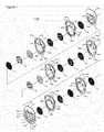
- Alkaline electrolyser module 100 in accordance with an aspect of the present invention is shown generally at 100 in Figure 1.
- Figure 1 shows about half of an alkaline electrolyser module with 4 cells for illustrative purposes only; the other half of the electrolyser module would be a mirror image (on either side of feature 12, which in this case represents the midpoint of the electrolyser module). In practice, typically greater numbers of cells would be incorporated.
- Alkaline electrolyser module 100 includes structural plates 10, end pressure plates 11, anodes 13, cathodes 14, membranes 15, current carriers 16, bipolar plates 17, and optionally, one or more intermediate pressure plates 12 interspersed between structural plates along the length of the electrolyser module.
- the structural plates 10, end pressure plates 11 and intermediate pressure plates 12 comprise at least a body having a sidewall extending between opposite end faces.
- structural plates 10 cathode structural plates 10a and anode structural plates 10b.
- special structural plates 10c and 10d can optionally be used on either side of the one or more optional intermediate pressure plate 12 and also optionally adjacent to either or both of the end pressure plates 11, respectively, e.g., to help to accommodate cooling conduits (e.g., cooling tubes or cooling coils).
- the term "plate” refers to structural plates, special structural plates, end pressure plates and intermediate pressure plates.
- Suitable seals e.g., o-ring gaskets, not shown
- o-ring gaskets also are understood to be included.
- each structural plate 10a and 10b and special structural plate 10c and 10d holds two internal reinforcing means 60a and 60b as inserts in holding features located on the front faces of the structural plates.
- adjacent structural plates may share a set of one or more internal reinforcing means, which are "sandwiched" between the adjacent structural plates, one having holding features for the internal reinforcing means on its front face, the other having holding features on its back face.
- Additional variations also can be considered; for example, all of the structural plates which are reinforced can have holding features for the internal reinforcing means on their back faces, or on both their front faces and back faces.
- not all of the structural plates may necessarily require internal reinforcing means; for example, if special structural plates are used, especially at moderate pressures, they may not require internal reinforcing means, since they lack fluid flow passages (i.e., they contain more material), and also they are inherently reinforced to some extent by the adjacent end pressure plate 11 or intermediate pressure plates 12. Accordingly, some of the structural plates, e.g., one or more special structural plates, may be made used without internal reinforcing means. Also, structural plates adjacent to an end pressure plate or an intermediate pressure plate may be directly mechanically reinforced by embedding them into the adjacent end pressure plate or intermediate pressure plate. However, there is little benefit to not utilizing the internal reinforcing means, since they increase part performance and lifetime at relatively little additional cost.
- Alkaline electrolyser module 100 thus comprises a plurality of electrolysis cells and associated degassing chambers 19.
- the electrolysis cells preferably are located at the bottom part of the electrolyser module 100, and the associated degassing chambers 19 preferably are located at the top part of the electrolyser module 100, surmounting the electrolysis cells.
- the electrolysis cells comprise cathode and anode half cell chambers 20a and 20b defined by two adjacent structural plates, as well as a cathode 14, an anode 13, a membrane 15, and current collectors 16. More than one current collector 16 can be used per half cell chamber 20a and/or 20b.
- Bipolar plates 17 physically separate and provide electrical communication between adjacent electrolysis cells.
- End pressure plates 11 and intermediate pressure plates 12 optionally include suitably coated or plated electrically conducting areas or separate parts 48 and 49, respectively, to facilitate electrical current flow through the portions of the end pressure plates and intermediate pressure plates corresponding to the active cell area.
- End pressure plates 11 and intermediate pressure plates 12 can be made of, e.g., one or more of steel, stainless steel, plated or coated steel, plated or coated stainless steel, nickel and nickel alloy, or other metals, plated metals or coated metals, or non-plated (the term "metals" is to be understood to include both metals and metal alloys).
- each cathode half cell chamber 20a is in direct fluid communication with the hydrogen degassing chamber 19a via a gas-liquid flow passage 21a, and a degassed liquid flow passage 22a.
- each anode half cell chamber 20b is in direct fluid communication with the oxygen degassing chamber 19b via a gas-liquid flow passage 21b, and a degassed liquid flow passage 22b.
- Separated hydrogen gas exits through hydrogen gas discharge passage 25, which extends radially through to the hydrogen degassing chamber; separated oxygen gas exits through separated oxygen gas discharge passage 26, which extends radially through to the oxygen degassing chamber.
- Gas discharge passages 25 and 26 typically are contained in the intermediate pressure plate 12, or in one or both of the end pressure plates 11.
- Feed water is introduced to one or both of the hydrogen and oxygen degassing chambers 19a and 19b through feed water passages (not shown), which also typically are located in the intermediate pressure plate 12 or in one or both of the end pressure plates 11.
- Electrical current is supplied to the cell portion of electrolyser module 100 by, for example, a DC power supply, most commonly via positive and negative electrical connections to end pressure plates 11, and optionally with a non-current carrying electrical ground connection to intermediate pressure plate 12 at the midpoint of electrolyser module 100.
- Separate liquid drains 47a and 47b for each of the hydrogen side (cathode drain) and the oxygen side (anode drain) respectively, are located at the bottom of one or more of the intermediate pressure plates 12 and the end pressure plates 11.
- the liquid drains are in fluid communication with either the cathode half cell chambers and hydrogen degassing chamber, or the anode half cell chambers and oxygen degassing chamber through a series of draining conduits in the structural plates, as described below.
- the liquid drains drain liquid (electrolyte) from the electrolyser module, for purposes such as long term shut down, maintenance, transport, sampling, etc., or for purposes such as removing bleed stream(s), to maintain the purity of the liquid (electrolyte) in the electrolyser module.
- the drains comprise two separate drains, a cathode drain for the cathode (hydrogen) portions of the electrolyser module, and an anode drain for the anode (oxygen) portions of the electrolyser module.
- a bleed stream of relatively impure liquid (electrolyte) can be taken from inside alkaline water electrolyser module 100 via one or both of liquid drains 47a and 47b, intermittently or continuously if/as required, and replaced with new liquid (electrolyte), in order to help to maintain acceptable purity of the liquid.
- each of the cathode drain and the anode drain comprise a plurality of connecting draining passages connecting the bottom portions of either each of the cathode half cell chambers or each of the anode half cell chambers to one or more draining manifolds. Note that by draining the half cell chambers, the corresponding degassing chambers also are drained, since they are in fluid communication with the half cell chambers through the degassed liquid passages and the gas-liquid passages.
- the cathode drain and the anode drain can be, but are not necessarily, similar. The cathode drain will be described here for illustrative purposes.
- the cathode draining passages comprise long passages with relatively small cross sectional areas connecting the bottom portion of the cathode half cell chambers with one or more cathode draining manifolds.
- the cathode draining manifolds are located below the cathode half cell chambers in order that draining can be achieved by gravity head, and extend at least part way along the length of the electrolyser module.
- the lengths of the draining passages for the cathode half cells can be extended by using paths comprised in more than one structural plate.
- the draining passages are internal passages near the bottom part of the cathode half cell chamber, which then become surface passages that follow a long downward path in order to render stray current flows during operation negligible.
- the passage then travels through one of the adjacent anode plates to the next cathode plate, where it once again becomes a surface passage with a long path, before joining one of the cathode draining manifolds.
- More than one cathode draining manifold can be used in order to further limit stray current flows.
- the one or more cathode draining manifolds connect to a draining point.
- the draining point comprises a draining port with a valve, located in the bottom portion of one of the intermediate pressure plates or one of the end pressure plates. There can be more than one draining point in the electrolyser module.
- each of the cathode drain and the anode drain also comprise draining channels for each half cell.
- similar approaches are used for both the cathode drain and the anode drain.
- the cathode drain will be described here for illustrative purposes.
- the main features of the cathode drain are shown in Figure 7 , which shows a series of three adjacent structural plates (two cathode structural plates and one anode structural plate) in the electrolyser module.
- the starting point of the cathode draining passage 80 for each cathode half cell is located in the degassed liquid passage 22a, near its point of connection to the cathode half cell chamber opening 20a.
- the cathode draining passage 80 is connected directly at or near the bottom of the cathode half cell chamber opening 20a.
- the cathode draining passage 80 initially is an internal passage, passing through the thickness of the cathode structural plate 10a to the opposing face of adjacent anode structural plate 10b, where it becomes a surface passage that creates a long path in order to render stray current flows during operation negligible.
- the periphery of the area defined by the surface passages in the face of anode structural plate 10b is sealed, preferably by an o-ring (not shown) that is seated in a holding feature (not shown).
- the cathode draining passage 80 then once again becomes an internal passage, passing through the thickness of anode structural plate 10b to degassed liquid passage 22a in the adjacent cathode structural plate 10a.
- This multi-structural plate configuration is then repeated until a draining point is reached.
- the draining point comprises a draining port with internal channels connecting to a valve, located in the bottom portion of one of the intermediate pressure plates 12 or one of the end pressure plates 11. There can be more than one draining point in the electrolyser module.
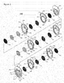
- a PEM electrolyser module in accordance with an aspect of the present invention is shown generally at 200 in Figure 2.
- Figure 2 shows about half of a PEM electrolyser module with 4 cells for illustrative purposes only; the other half of the electrolyser module would be a mirror image (on either side of feature 12, which in this case represents the midpoint of the electrolyser module). In practice, typically greater numbers of cells would be incorporated.
- PEM electrolyser module 200 includes structural plates 10, end pressure plates 11, membrane-electrode assemblies (MEA's) 33, optionally electrode backing layers 33a and 33b, current carriers 34, bipolar plates 35 and optionally, one or more intermediate pressure plates 12.
- MEA's membrane-electrode assemblies
- the structural plates 10, end pressure plates 11 and intermediate pressure plates 12 comprise at least a body having a sidewall extending between opposite end faces.
- a typical MEA consists of a membrane and electrodes coated onto opposite faces of the membrane; a cathode coated onto one face of the membrane, and an anode coated onto the opposite face of the membrane. Thus, the membrane is in communication with each of the two electrodes for providing ionic conduction.
- a typical MEA consists of a membrane, a cathode coated onto one side of the membrane, and an anode coated onto the other side of the membrane.
- the electrode backing layers 33a and 33b also can be incorporated into the MEA 33.
- each structural plate 10a and 10b and special structural plate 10c and 10d also holds two internal reinforcing means 60a and 60b in holding features, which may be recesses or grooves, located on the front faces of the structural plates.
- adjacent structural plates may share a set of one or more internal reinforcing means, which are "sandwiched" between the adjacent structural plates, one having holding features for the internal reinforcing means on its front face, the other having holding features on its back face.
- Additional variations also can be considered; for example, all of the structural plates which are reinforced can have holding features for the internal reinforcing means on their back faces, or on both their front faces and back faces.
- not all of the structural plates may necessarily require internal reinforcing means; for example, if special structural plates are used, especially at moderate pressures, they may not require internal reinforcing means, since they lack fluid flow passages (i.e., they contain more material), and also they are inherently reinforced to some extent by the adjacent end pressure plate 11 or intermediate pressure plates 12. Accordingly, some of the structural plates, e.g., one or more special structural plates, may be made used without internal reinforcing means. Also, structural plates adjacent to an end pressure plate or an intermediate pressure plate may be directly mechanically reinforced by embedding them into the adjacent end pressure plate or intermediate pressure plate. However, there is little benefit to not utilizing the internal reinforcing means, since they increase part performance and lifetime at relatively little additional cost.
- PEM electrolyser module 200 thus comprises a plurality of electrolysis cells and associated hydrogen degassing chamber 19a and oxygen degassing chamber 19b.
- the PEM electrolysis cells preferably are located at the bottom part of the electrolyser module 200, and the associated degassing chambers 19a and 19b preferably are located at the top part of the electrolyser module 200, surmounting the PEM electrolysis cells.
- the PEM electrolysis cells comprise cathode and anode half cell chambers 20a and 20b defined by two adjacent structural plates, as well as a MEA 33, electrode backing layers 33a and 33b, and the current collectors 34. Bipolar plates 35 physically separate and provide electrical communication between adjacent PEM electrolysis cells.
- End pressure plates 11 and intermediate pressure plates 12 optionally include suitably coated or plated electrically conducting areas or separate parts 48 and 49, respectively, to facilitate electrical current flow through the portions of the end pressure plates and intermediate pressure plates corresponding to the active cell area.
- End pressure plates 11 and intermediate pressure plates 12 can be made of, e.g., one or more of steel, stainless steel, plated steel, plated stainless steel, or other metals, plated metals or coated metals (the term "metals" is to be understood to include metals and metal alloys).
- each cathode half cell chamber 20a is in direct fluid communication with the hydrogen degassing chamber 19a via a gas-liquid flow passage 21a, and a degassed liquid flow passage 22a.
- each anode half cell chamber 20b is in direct fluid communication with the oxygen degassing chamber 19b via a gas-liquid flow passage 21b, and a degassed liquid flow passage 22b.
- Separated hydrogen gas exits through hydrogen gas discharge passage 25, which extends radially through to the hydrogen degassing chamber; separated oxygen gas exits through separated oxygen gas discharge passage 26, which extends radially through to the oxygen degassing chamber.
- Gas discharge passages 25 and 26 typically are contained in the intermediate pressure plate 12, or in one or both of the end pressure plates 11.
- Feed water is introduced to one or both of the hydrogen and oxygen degassing chambers 19a and 19b through feed water passages (not shown), which also typically are located in the intermediate pressure plate 12 or in one or both of the end pressure plates 11.
- Electrical current is supplied to the cell portion of electrolyser module 200 by, for example, a DC power supply, most commonly via positive and negative electrical connections to end pressure plates 11, and optionally with a non-current carrying electrical ground connection to intermediate pressure plate 12 at the midpoint of electrolyser module 200.
- Separate liquid drains 47a and 47b for each of the hydrogen (cathode) side and the oxygen (anode) side respectively, are located at the bottom of one or more of the intermediate pressure plates 12 and the end pressure plates 11.
- the liquid drains are in fluid communication with either the cathode half cell chambers and hydrogen degassing chamber or the anode half cell chambers and oxygen degassing chamber through respective series of draining conduits in the structural plates, as described below.
- the liquid drains drain liquid (water) from the PEM water electrolyser module, for purposes such as long term shut down, maintenance, transport, sampling, etc.
- a bleed stream of relatively impure liquid (water) can be taken from inside PEM water electrolyser module 200 via one or both of liquid drains 47a and 47b, intermittently or continuously if/as required, and replaced by relatively pure liquid (feed water) in order to help to maintain acceptable purity of the liquid (water).
- a closed-loop liquid purification and recycle approach can be used; e.g., a stream of relatively impure liquid (water) can be taken from inside PEM water electrolyser 200 via one or both of liquid drains 47a and 47b, intermittently or continuously if/as required, purified by water purification means such as ion exchange and/or other means as is known in the art, and re-introduced inside PEM water electrolyser 200, e.g., along with or in place of new feed water.
- the water purification means can be that used to purify feed water.
- each of the cathode drain and the anode drain comprise a plurality of connecting draining passages connecting the bottom portions of either each of the cathode half cell chambers or each of the anode half cell chambers to one or more draining manifolds. Note that by draining the half cell chambers, the corresponding degassing chambers also are drained, since they are in fluid communication with the half cell chambers through the degassed liquid passages and the gas-liquid passages.
- the cathode drain and the anode drain can be, but are not necessarily, similar. The cathode drain will be described here for illustrative purposes.
- the cathode draining passages comprise passages between the bottom portion of the cathode half cell chambers and one or more cathode draining manifolds.
- the cathode draining manifolds are located below the cathode half cell chambers in order that draining can be achieved by gravity head, and extend at least part way along the length of the electrolyser module.
- the draining passages are internal passages near the bottom part of the cathode half cell chamber, which then become surface passages. The passage then extends through one of the adjacent anode plates to the next cathode plate, where it once again becomes a surface passage, before joining to one of the cathode draining manifolds.
- More than one cathode draining manifold can be used.
- the one or more cathode draining manifolds connect to a draining point.
- the draining point comprises a draining port with a valve, located in the bottom portion of one of the intermediate pressure plates or one of the end pressure plates.
- each of the cathode drain and the anode drain also comprise draining channels for each half cell.
- similar approaches are used for both the cathode drain and the anode drain.
- the cathode drain will be described here for illustrative purposes.
- the main features of the cathode drain are shown in Figure 7 , which shows a series of three adjacent structural plates (two cathode structural plates and one anode structural plate) in the electrolyser module.
- the starting point of the cathode draining passage 80 for each cathode half cell is located in the degassed liquid passage 22a, near its point of connection to the cathode half cell chamber opening 20a.
- the cathode draining passage 80 is connected directly at or near the bottom of the cathode half cell chamber opening 20a.
- the cathode draining passage 80 initially is an internal passage, passing through the thickness of the cathode structural plate 10a to the opposing face of adjacent anode structural plate 10b, where it becomes a surface passage.
- the periphery of the area defined by the surface passages in the face of anode structural plate 10b is sealed, preferably by an o-ring (not shown) that is seated in a holding feature (not shown).
- the cathode draining passage 80 then once again becomes an internal passage, passing through the thickness of anode structural plate 10b to degassed liquid passage 22a in the adjacent cathode structural plate 10a.
- This multi-structural plate configuration is then repeated until a draining point is reached.
- the draining point comprises a draining port with internal channels connecting to a valve, located in the bottom portion of one of the intermediate pressure plates 12 or one of the end pressure plates 11. There can be more than one draining point in the electrolyser module.
- the bottom portions of degassing chambers 19a and 19b can be in fluid (liquid only) communication, e.g., via one or more liquid communication passages.
- liquid communication passages are: internal passages contained in one of more of intermediate pressure plate 12, end pressure plates 11 and special structural plates 10c and 10d; passages formed by surface channels in at least one of the opposite end faces of one or more of intermediate pressure plate 12 and end pressure plates 11, at least when in face-to-face juxtaposition with adjacent special structural plates 10c and 10d, respectively; passages formed by surface channels in at least one of the opposite end faces of one or more of special structural plates 10c and 10d, at least when in face-to-face juxtaposition with adjacent intermediate pressure plate 12, end pressure plate 11, respectively, or structural plates 10a and 10b; and, external passages, comprised of, e.g., tube or pipe, in liquid communication with degassing chambers 19a and 19b via internal passages in intermediate pressure plate 12 or end pressure plate 11.
- external passages comprised of, e.g., tube or pipe, in liquid communication with degassing chambers 19a and 19b via internal passages in intermediate pressure plate 12 or end pressure plate 11.
- FIG. 1 and 2 Illustrative examples are shown in Figures 1 and 2 : (i) features 28a and 28b in special structural plates 10c; (ii) features 29a and 29b in special structural plates 10d; and, (iii) feature 40, which is tube or pipe in liquid communication with the lower portion of the hydrogen degassing chamber and the oxygen degassing chamber via respective interior passages in intermediate pressure plate 12; (iv) features 45a and 45b in intermediate pressure plate 12 and features 46a and 46b in end pressure plate 11.
- Features 28a, 28b, 29a, 29b, 45a, 45b, 46a and 46b are shown as surface channels, but could be corresponding internal passages.
- Such liquid communication between degassing chambers 19a and 19b may facilitate (near) equalization of the liquid levels in the degassing chambers, and thereby the hydrogen side and oxygen side pressures during operation, and further, may facilitate rapid, passive response for correction of operational upsets.
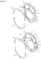
- Structural plates for an electrolyser module in accordance with an aspect of the present invention are shown in Figure 3.
- Figure 3 shows a preferred embodiment in which structural plate 10a defines one half cell chamber opening 20a and two degassing chamber openings 19a and 19b; it is understood that each structural plate can define more than one of each type of opening.
- the structural plates define at least when in face to face juxtaposition, passages for fluid flow inside the electrolyser stack.
- Structural plate 10a defines one or more gas-liquid flow passages 21a, which provide direct fluid communication between the top part of the half cell chamber opening 20a to one of the degassing chamber openings 19a and 19b.
- Structural plate 10a further defines one or more degassed liquid flow passages 22a, which provide direct fluid communication between the bottom part of the half cell chamber opening 20a to one of the degassing chamber openings 19a and 19b.
- Gas-liquid flow passages 21 become interior passages (slot-shaped through holes) near the top of half cell chamber opening 20; similarly, degassed liquid flow passages 22 become interior passages (slot-shaped through holes) near the bottom of half cell chamber opening 20.
- Structural plate 10a also includes holding features (not shown) for locating and holding seals (e.g., o-ring gaskets) and holding features 50 for locating and holding one or more internal reinforcing means 60, at least when in face to face juxtaposition with another structural plate, an end pressure plate, or an intermediate pressure plate.
- the holding features 50 may be a recess or groove in which the reinforcing means 60a and 60b may fit.
- two internal reinforcing means 60a and 60b comprising curved inserts are used; one spanning the top portion of the structural plate, and one spanning the bottom portion of the structural plate.
- the structural plates are made of a suitable electrically insulating plastic or fiber-reinforced plastic.
- suitable plastics include polyoxymethylene (POM), polypropylene, polyphenylene oxide (PPO), polyphenylene sulphide (PPS) and the like, and in particular, polysulfone.
- Structural plates 10a and 10b shown in Figure 3 correspond to cathode (hydrogen) structural plates 10a and anode structural plates 10b in Figures 1 and 2 .
- Figure 3 also shows features for a particularly preferred feed water addition system, which comprises entry passages in one or more of the end pressure plates 11 and/or one or more intermediate pressure plates 12, which are in fluid communication on one end with an external feed water source, typically with water purification, e.g., by reverse osmosis and/or ion exchange, and by filters such as carbon filters, and on the other end with one or more feed water manifolds formed by feed water openings 102 in structural plates 10.
- Feed water openings 102 in turn further fluidly communicate in one or more of the structural plates 10 with one or more of the first and second degassing chambers 19a and 19b via water flow passages 103.
- water flow passages 103 in cathode structural plates 10a are in fluid communication with hydrogen degassing chamber 19a
- water flow passages 103 in anode structural plates 10b are in fluid communication with oxygen degassing chamber 19b, or vice-versa, such that water flow passages connect to opposite degassing chambers in adjacent structural plates.
- separate feed water passages are used to add liquids to hydrogen degassing chamber 19a and oxygen degassing chamber 19b.
- the internal reinforcing means for all the embodiments described herein have better mechanical properties (strength, elastic modulus) than the plastic or fiber reinforced plastic comprising the bodies of the structural plates, and preferably are easily installed, readily available, and low cost.
- curved inserts are used as the internal reinforcing means.
- Two internal reinforcing means are used per structural plate; one spanning the top portion of each structural plate, and one spanning the bottom portion of each structural plate, as illustrated in Figure 3 (60a and 60b).
- Holding features 50 for mounting the internal reinforcing means are located on the front faces of the structural plates for relative ease of assembly, but alternatively can be located on the back faces of the structural plates, or on the front side and then the back side of alternate structural plates, or on both faces of the structural plates.
- Figure 4 shows an example of an alternative embodiment in which holding features 50 are located on the front face of structural plate 10a and on the back face of the next structural plate 10b, with a single set of internal reinforcing means shared between adjacent structural plates.
- a view of the back face of structural plate 10b (180° rotational view) is shown separately at the bottom of Figure 4 for clarity.
- the internal reinforcing means 60a and 60b are straightforwardly installed during assembly of the electrolyser module by inserting them in the holding features 50.
- the holding features 50 optionally include one or more pins at through-holes in the internal reinforcing means (51 in Figure 3 ), connected to the structural plate, to keep the internal reinforcing means 60a and 60b mounted in place during assembly of the electrolyser module.
- the internal reinforcing means are preferably comprised of, but not limited to, metal with or without plating or coating (e.g., polymer-coated metal), and most preferably, at least for alkaline electrolyser modules or stacks, steel or stainless steel, or optionally polymer-coated steel or stainless steel.
- the term “metal” is to be understood to include both metals and metal alloys.
- the material comprising the internal reinforcing means must provide not only sufficient strength and elastic modulus, but also appropriate chemical resistance; for example, aluminum or aluminum alloys, copper or copper alloys, and titanium or titanium alloys are not preferred for use in alkaline electrolyser modules or stacks, but may be considered for use in PEM electrolyser modules or stacks as lighter weight alternatives.
- An example of a suitable internal reinforcing means thickness is 6 mm (assuming it is mounted in a single structural plate).
- the internal reinforcing means support and mitigate outward displacement of the polymeric structural plate material over time.
- the internal reinforcing means also enable minimization of plastic material around the periphery of the structural plates, reducing cost, part size, and shot size for injection molding.
- the tendency for asymmetrical structural plates to experience displacement and corresponding stress in a certain direction can be counteracted by counter-stressing the structural plate in the opposite direction during module assembly.
- the structural plate shown in Figure 3 can be compressed radially inwardly in the horizontal direction at certain locations (near the middle of the structural plate, at the locations indicated as "C" in this case) during module assembly, with the reinforcing means correspondingly slightly inwardly bent at those locations, such that the reinforcing means tend to counteract the tendency for outward displacement through this area.
- This approach has been found to significantly reduce stresses in the complex fluid flow features in the middle of the structural plate.
- Some or all of the holding features for the reinforcing means can optionally remain unused, in accordance with the pressure containment requirements. However, for lower pressure containment requirements (e.g., 5 - 10 bar), inclusion of the reinforcing means can ensure long-term mechanical integrity of the structural plates with relatively little increased initial cost.
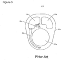
- EXAMPLE 1 Stresses in a structural plate for an electrolyser module according to a prior design were modeled by finite element analysis (FEA).
- the general structural plate configuration was as shown in Figure 5 .
- the outermost dimensions of the structural plate were 1505 mm wide, 1,828 mm high, and 12 mm thick.
- the half cell chamber opening was 6,000 cm 2 .
- the structural plate was made of polysulfone. Modeling at 25 bar internal pressure showed an unacceptable stress distribution with high stresses and displacements.
- EXAMPLE 2 Stresses in a structural plate for an electrolyser module according to the present invention were modeled by FEA.
- the general structural plate and internal reinforcing means configuration as shown in Figure 6 .
- the internal reinforcing means 65 was a single, 6 mm thick continuous steel insert, with a corresponding holding feature 66 around the periphery of the front face of the structural plate, as shown in Figure 6 .
- the outermost dimensions of the structural plate were 1,513 mm wide, 1830 mm high, and 12 mm thick.
- the half cell chamber opening was 6,000 cm 2 .
- the structural plate was made of polysulfone. The amount of polysulfone used was 35% less than the prior design part shown in Figure 5 . Modeling at 25 bar internal pressure showed an acceptable stress distribution with low stresses and displacement.
- the continuous internal reinforcement provided acceptably low stresses and displacements, it would be costly to fabricate with the required tolerances, cumbersome, and difficult to fit into the holding features in the structural plate.
- EXAMPLE 3 Stresses in a structural plate for an electrolyser module according to the present invention were modeled by FEA.
- the general structural plate and internal reinforcing means configuration was as shown in Figure 3 .
- the internal reinforcing means 60a and 60b comprised two 6 mm thick curved steel inserts as shown in Figure 3 ; one spanning the top portion of the structural plate, and one spanning the bottom portion of the structural plate.
- the holding features for the internal reinforcing means were in the front side of the structural plate, as shown in Figure 3 .
- the outermost dimensions of the structural plate were 1513 mm wide, 1,851 mm high, and 12 mm thick.
- the half cell chamber opening was 6,000 cm 2 .
- the structural plate was made of polysulfone.
- the amount of polysulfone used was 38% less than the prior art part shown in Figure 5 .
- Modeling at 25 bar internal pressure showed an acceptable stress distribution with low stresses and displacement.
- the structural plates were compressed inward 0.040 inches at the four points indicated as "C" in Figure 3 , in order to further reduce stresses at the complex fluid flow features in Figure 3 .
- the maximum stresses were 41% lower than those in Example 2.
- water electrolyser module of the present invention be used for large scale (e.g., MW scale) applications.
- an electrolyser stack comprises a plurality of structural plates each having a sidewall extending between opposite end faces with a half cell chamber opening, with at least two header flow passage openings and at least one footer flow passage opening extending through each structural plate between its opposite end faces.
- the structural plates are arranged in face to face juxtaposition between opposite end pressure plates.
- Each half cell chamber opening at least partially houses electrolytic half cell components comprising at least an electrode, a bipolar plate in electrical communication with the electrode, and a membrane communicating with the electrode for providing ionic conduction.
- the structural plates and half cell components therefore define an array of series connected electrolytic cells.
- the structural plates also define, at least when in face to face juxtaposition, passages for fluid flow inside the electrolyser stack.
- the electrolyser stack further comprises internal reinforcing means mounted to at least some of the structural plates for mitigating outward displacement of the structural plates.
- At least the structural plates to which internal reinforcing means are mounted further define, at least when in face to face juxtaposition, holding features for locating and holding at least part of one or more internal reinforcing means.
Landscapes
- Chemical & Material Sciences (AREA)
- Engineering & Computer Science (AREA)
- Chemical Kinetics & Catalysis (AREA)
- Electrochemistry (AREA)
- Materials Engineering (AREA)
- Metallurgy (AREA)
- Organic Chemistry (AREA)
- Inorganic Chemistry (AREA)
- Electrolytic Production Of Non-Metals, Compounds, Apparatuses Therefor (AREA)
- Cathode-Ray Tubes And Fluorescent Screens For Display (AREA)
Claims (13)
- Module électrolyseur comprenant une pluralité de plaques structurales ayant chacune une paroi latérale s'étendant entre des faces d'extrémité opposées présentant une ouverture de chambres de demi-cellules et au moins deux ouvertures de chambres de dégazage s'étendant à travers ladite plaque structurale entre lesdites faces d'extrémité opposées ;
lesdites plaques structurales étant agencées en juxtaposition face à face entre les plaques de pression d'extrémité opposées, chacune desdites ouvertures de chambres de demi-cellules logeant au moins en partie les composants de demi-cellules électrolytiques comprenant au moins une électrode, une plaque bipolaire en communication électrique avec ladite électrode, et une membrane communiquant avec ladite électrode pour fournir une conduction ionique, lesdites plaques structurales et lesdits composants de demi-cellules définissant un réseau de cellules électrolytiques connectées en série surmontées par au moins une chambre de dégazage ;
lesdites plaques structurales définissant, au moins lorsqu'elles sont en juxtaposition face à face, des passages pour l'écoulement de fluide à l'intérieur dudit module électrolyseur ;
ledit module électrolyseur comprenant en outre un ou plusieurs éléments de renforcement internes montés sur la périphérie d'au moins une plaque parmi lesdites plaques structurales pour limiter le déplacement vers l'extérieur desdites plaques structurales ;
au moins ladite au moins une plaque parmi lesdites plaques structurales définissant en outre des éléments de retenue dans au moins une face parmi une face avant et une face arrière desdites plaques structurales pour situer et retenir ladite au moins une partie parmi les un ou plusieurs éléments de renforcement internes. - Module électrolyseur selon la revendication 1, comprenant en outre au moins une plaque de pression intermédiaire, comprenant au moins un corps, intercalée entre lesdites plaques structurales dans le sens de la longueur dudit module électrolyseur.
- Module électrolyseur selon l'une quelconque des revendications 1 et 2, dans lequel lesdits un ou plusieurs éléments de renforcement internes comprennent deux éléments insérés incurvés montés sur chacune desdites au moins certaines desdites plaques structurales ; l'un recouvrant une partie supérieure de chacune desdites au moins certaines desdites plaques structurales, et l'autre recouvrant une partie inférieure de chacune desdites au moins certaines desdites plaques structurales.
- Module électrolyseur selon l'une quelconque des revendications 1 et 2, dans lequel lesdites plaques structurales sont comprimées radialement vers l'intérieur au niveau de certains emplacements pendant l'assemblage dudit module électrolyseur, lesdits un ou plusieurs éléments de renforcement internes étant de la même manière courbés vers l'intérieur au niveau desdits certains emplacements.
- Module électrolyseur selon l'une quelconque des revendications 1 et 2, comprenant en outre au moins un passage de communication de liquide pour la communication de liquide entre lesdites au moins première et seconde chambres de dégazage.
- Module électrolyseur selon la revendication 2, comprenant en outre au moins un passage d'eau d'alimentation passant par au moins une plaque parmi lesdites plaques de pression d'extrémité et ladite au moins une plaque de pression intermédiaire, et passant ensuite par lesdites plaques structurales.
- Module électrolyseur selon l'une quelconque des revendications 1 et 2, dans lequel lesdites plaques structurales sont composées d'une matière plastique et/ou d'une matière plastique renforcée de fibres.
- Module électrolyseur selon la revendication 7, dans lequel lesdits un ou plusieurs éléments de renforcement internes comprennent des éléments insérés ayant une résistance et un module élastique significativement plus élevés que ceux desdites matière plastique et/ou matière plastique renforcée de fibres.
- Module électrolyseur selon la revendication 8, dans lequel lesdits un ou plusieurs éléments de renforcement internes comprennent un métal, un métal plaqué et/ou un métal revêtu de polymère.
- Procédé de maintien de la pureté du liquide dans un module électrolyseur selon l'une quelconque des revendications 1 et 2 comprenant l'étape consistant à prélever un courant de purge de liquide impur dudit module électrolyseur et à remplacer ledit liquide impur par un nouveau liquide.
- Plaque structurale pour module électrolyseur ayant une paroi latérale s'étendant entre des faces d'extrémité opposées présentant une ouverture de chambres de demi-cellules et au moins deux ouvertures de chambres de dégazage s'étendant à travers ladite plaque structurale entre lesdites faces d'extrémité opposées ;
ladite plaque structurale définissant, au moins lorsqu'elle est en juxtaposition face à face avec une autre plaque structurale, une plaque de pression d'extrémité, et/ou une plaque de pression intermédiaire, des passages pour l'écoulement de fluide à l'intérieur dudit module électrolyseur ;
ladite plaque structurale définissant en outre, au moins lorsqu'elle est en juxtaposition face à face avec une autre plaque structurale, une plaque de pression d'extrémité, et/ou une plaque de pression intermédiaire, des éléments de retenue à la périphérie d'au moins une face parmi une face avant et une face arrière de ladite plaque structurale pour situer et retenir au moins une partie parmi les un ou plusieurs éléments de renforcement internes. - Empilement d'électrolyseurs comprenant une pluralité de plaques structurales ayant chacune une paroi latérale s'étendant entre des faces d'extrémité opposées présentant une ouverture de chambres de demi-cellules, au moins deux ouvertures de passage d'écoulement de sommet et au moins une ouverture de passage d'écoulement de base s'étendant à travers ladite plaque structurale entre lesdites faces d'extrémité opposées ;
lesdites plaques structurales étant agencées en juxtaposition face à face entre les plaques de pression d'extrémité opposées ;
chacune desdites ouvertures de chambres de demi-cellules logeant au moins en partie les composants de demi-cellules électrolytiques comprenant au moins une électrode, une plaque bipolaire en communication électrique avec ladite électrode, et une membrane communiquant avec ladite électrode pour fournir une conduction ionique, lesdites plaques structurales et lesdits composants de demi-cellules définissant un réseau de cellules électrolytiques connectées en série ;
lesdites plaques structurales définissant, au moins lorsqu'elles sont en juxtaposition face à face, des passages pour l'écoulement de fluide à l'intérieur dudit empilement d'électrolyseurs ;
ledit empilement d'électrolyseurs comprenant en outre un ou plusieurs éléments de renforcement internes montés sur la périphérie d'au moins une plaque parmi lesdites plaques structurales pour limiter le déplacement vers l'extérieur desdites plaques structurales ;
au moins ladite au moins une plaque parmi lesdites plaques structurales définissant en outre des éléments de retenue dans au moins une face parmi une face avant et une face arrière de ladite plaque structurale pour situer et retenir au moins une partie parmi lesdits un ou plusieurs éléments de renforcement internes. - Empilement d'électrolyseurs selon la revendication 12, comprenant en outre au moins une plaque de pression intermédiaire, comprenant au moins un corps, intercalée entre lesdites plaques structurales dans le sens de la longueur dudit empilement d'électrolyseurs.
Applications Claiming Priority (2)
| Application Number | Priority Date | Filing Date | Title |
|---|---|---|---|
| US201261700534P | 2012-09-13 | 2012-09-13 | |
| PCT/CA2013/000768 WO2014040166A1 (fr) | 2012-09-13 | 2013-09-11 | Module d'électrolyseur d'eau renforcé à l'intérieur |
Publications (3)
| Publication Number | Publication Date |
|---|---|
| EP2895644A1 EP2895644A1 (fr) | 2015-07-22 |
| EP2895644A4 EP2895644A4 (fr) | 2016-05-25 |
| EP2895644B1 true EP2895644B1 (fr) | 2018-07-11 |
Family
ID=50232131
Family Applications (1)
| Application Number | Title | Priority Date | Filing Date |
|---|---|---|---|
| EP13837900.3A Active EP2895644B1 (fr) | 2012-09-13 | 2013-09-11 | Module d'électrolyseur d'eau renforcé à l'intérieur |
Country Status (6)
| Country | Link |
|---|---|
| US (1) | US9187833B2 (fr) |
| EP (1) | EP2895644B1 (fr) |
| CN (1) | CN104619887B (fr) |
| CA (1) | CA2883708C (fr) |
| IN (1) | IN2015DN01037A (fr) |
| WO (1) | WO2014040166A1 (fr) |
Families Citing this family (11)
| Publication number | Priority date | Publication date | Assignee | Title |
|---|---|---|---|---|
| WO2013191140A1 (fr) * | 2012-06-18 | 2013-12-27 | 旭化成株式会社 | Unité d'électrolyse et cellule électrolytique bipolaire pour eau alcaline |
| AU2014295913A1 (en) | 2013-07-31 | 2016-02-11 | Aquahydrex Pty Ltd | Method and electrochemical cell for managing electrochemical reactions |
| WO2017184877A1 (fr) | 2016-04-21 | 2017-10-26 | Fuelcell Energy, Inc. | Système de pile à combustible haute performance à exportation d'hydrogène et de gaz de synthèse |
| US10541433B2 (en) | 2017-03-03 | 2020-01-21 | Fuelcell Energy, Inc. | Fuel cell-fuel cell hybrid system for energy storage |
| US10573907B2 (en) | 2017-03-10 | 2020-02-25 | Fuelcell Energy, Inc. | Load-following fuel cell system with energy storage |
| US10947134B2 (en) * | 2018-08-30 | 2021-03-16 | Osvaldo Gaona Solis | Hydrogen generator |
| US20220145479A1 (en) | 2019-02-01 | 2022-05-12 | Aquahydrex, Inc. | Electrochemical system with confined electrolyte |
| CN109868484B (zh) * | 2019-04-04 | 2021-08-10 | 黄立 | 一种气体产生装置 |
| CN109898094A (zh) * | 2019-04-19 | 2019-06-18 | 吕志超 | 一种高压水电解槽 |
| DK181123B1 (en) * | 2021-01-22 | 2023-01-16 | Stiesdal Hydrogen As | An electrolysis system |
| WO2023237535A1 (fr) * | 2022-06-07 | 2023-12-14 | Industrie De Nora S.P.A. | Structure d'encadrement pour électrolyseur |
Family Cites Families (56)
| Publication number | Priority date | Publication date | Assignee | Title |
|---|---|---|---|---|
| US2075688A (en) | 1935-01-10 | 1937-03-30 | Bamag Meguin Ag | Electrolytic apparatus |
| CH202238A (de) * | 1937-04-28 | 1939-01-15 | Bamag Meguin Aktiengesellschaf | Verfahren zur Herstellung von Zellenrahmen für Elektrolyseure mit bipolaren, ohne metallische Stromzuführung hintereinander geschalteten Elektroden. |
| CH280175A (de) | 1949-11-30 | 1952-01-15 | Lonza Ag | Verfahren zur Inbetriebnahme von mehrzelligen Überdruck-Elektrolyseuren. |
| GB1595193A (en) | 1977-03-04 | 1981-08-12 | Ici Ltd | Diaphragm cell |
| JPS55138086A (en) | 1979-04-10 | 1980-10-28 | Asahi Glass Co Ltd | Preparation of hydrogen |
| AT365090B (de) * | 1980-04-16 | 1981-12-10 | Inkomag | Filtriereinrichtung |
| JPS5933193B2 (ja) | 1980-12-04 | 1984-08-14 | 大阪曹達株式会社 | 水処理用薬剤の製法 |
| US4439298A (en) * | 1982-07-26 | 1984-03-27 | Olin Corporation | Composite fiber reinforced plastic frame |
| DE3425163A1 (de) * | 1984-07-07 | 1986-01-16 | Seitz Enzinger Noll Maschinenbau Ag, 6800 Mannheim | Filterpresse fuer die anschwemmfiltration |
| CH672142A5 (fr) | 1985-07-17 | 1989-10-31 | Metkon Sa | |
| FR2601387B1 (fr) * | 1986-07-09 | 1990-10-19 | Solvay | Electrolyseur du type filtre-presse |
| GB2263734B (en) | 1992-01-31 | 1995-11-29 | Declan Nigel Pritchard | Smoothing electrical power output from means for generating electricity from wind |
| JPH07233493A (ja) | 1994-02-22 | 1995-09-05 | Mitsubishi Heavy Ind Ltd | 水電解システム用電力変換装置 |
| WO1995028510A1 (fr) | 1994-04-19 | 1995-10-26 | Hydrogen Technology Ltd. | Perfectionnements se rapportant aux systemes d'electrolyse et a la disponibilite d'un excedent d'energie |
| US5512145A (en) | 1994-10-07 | 1996-04-30 | The Cooper Union For The Advancement Of Science And Art | Energy conversion system |
| DE29622000U1 (de) | 1996-12-19 | 1997-02-13 | Mtu Friedrichshafen Gmbh | Druckwassergekapselter Elektrolyseur |
| NL1005081C2 (nl) | 1997-01-24 | 1998-07-27 | Zilvold Tieleman Hydro Technie | Inrichting voor het uitvoeren van een elektrolyse, een hierin toepasbaar celelement, werkwijze voor het uitvoeren van een elektrolyse in een dergelijke inrichting, werkwijze voor het bereiden van chloordioxide, reactor voor het uitvoeren van een dergelijke werkwijze en een installatie voor het bereiden van chloordioxide. |
| RU2125539C1 (ru) | 1998-02-10 | 1999-01-27 | Оганесов Владимир Емельянович | Установка для обработки воды ионами серебра |
| EP0995818A1 (fr) | 1998-10-12 | 2000-04-26 | Hydrogen Systems N.V. | Module d'électrolyse fonctionnant à haute pression |
| CA2271448A1 (fr) | 1999-05-12 | 2000-11-12 | Stuart Energy Systems Inc. | Reseau de distribution d'energie |
| CA2353210C (fr) | 2000-07-19 | 2006-07-11 | Toyota Jidosha Kabushiki Kaisha | Appareil a piles a combustible |
| JP2002088493A (ja) | 2000-09-14 | 2002-03-27 | Honda Motor Co Ltd | 水電解システム |
| US6500319B2 (en) | 2001-04-05 | 2002-12-31 | Giner Electrochemical Systems, Llc | Proton exchange membrane (PEM) electrochemical cell having an integral, electrically-conductive, compression pad |
| JP2002371396A (ja) | 2001-06-13 | 2002-12-26 | Shinko Pantec Co Ltd | 電解装置及び電解方法 |
| AU2002356561A1 (en) | 2001-10-12 | 2003-04-22 | Proton Energy Systems, Inc. | Method and system for bridging short duration power interruptions |
| DE10150557C2 (de) | 2001-10-15 | 2003-12-18 | Mtu Friedrichshafen Gmbh | Druckelektrolyseur und Verfahren zum Betrieb eines solchen |
| EP1461474B1 (fr) | 2001-12-05 | 2011-11-30 | Oculus Innovative Sciences, Inc. | Procede et dispositif de production d'eau aux potentiels d'oxydo-reduction negatifs et positifs |
| WO2003076800A2 (fr) | 2002-03-08 | 2003-09-18 | Ocean Wind Energy Systems | Eolienne situee en mer |
| JP3970083B2 (ja) | 2002-04-23 | 2007-09-05 | 住友電気工業株式会社 | レドックスフロー電池システムの運転方法 |
| US8480891B2 (en) * | 2002-09-30 | 2013-07-09 | Micronics, Inc. | Filter assembly |
| US6864596B2 (en) | 2002-10-07 | 2005-03-08 | Voith Siemens Hydro Power Generation, Gmbh & Co. Kg | Hydrogen production from hydro power |
| WO2004049479A2 (fr) | 2002-11-27 | 2004-06-10 | Hydrogenics Corporation | Systeme d'alimentation regeneratif et composants de celui-ci |
| EP1464730A1 (fr) | 2003-04-04 | 2004-10-06 | CASALE ChEMICALS S.A. | Structure de cadre pour réacteur électrochimique de type filtre-presse |
| US7759812B2 (en) | 2003-04-30 | 2010-07-20 | Terra Moya Aqua, Inc. | Integrated power plant that utilizes renewable and alternative energy sources |
| US6956300B2 (en) | 2003-08-04 | 2005-10-18 | Andrew Roman Gizara | Gimbal-mounted hydroelectric turbine |
| US20050044853A1 (en) | 2003-09-02 | 2005-03-03 | Kazutora Yoshino | Ecology system |
| WO2005028713A1 (fr) | 2003-09-22 | 2005-03-31 | Hydrogenics Corporation | Systeme d'empilage de cellules d'electrolyseur |
| EP1528126A1 (fr) | 2003-10-30 | 2005-05-04 | Vandenborre Hydrogen Systems N.V. | Module d'électrolyseur intégré avec separateur gaz/liquide |
| CA2455689A1 (fr) | 2004-01-23 | 2005-07-23 | Stuart Energy Systems Corporation | Systeme de commande de reseau a hydrogene |
| US7510640B2 (en) | 2004-02-18 | 2009-03-31 | General Motors Corporation | Method and apparatus for hydrogen generation |
| JP2005330515A (ja) | 2004-05-18 | 2005-12-02 | Mitsubishi Heavy Ind Ltd | 自然エネルギー利用水電解システム |
| WO2006009673A2 (fr) | 2004-06-18 | 2006-01-26 | General Motors Corporation | Systeme et sous-systeme pour la production et pour l'utilisation d'hydrogene |
| US8057646B2 (en) | 2004-12-07 | 2011-11-15 | Hydrogenics Corporation | Electrolyser and components therefor |
| US7245039B2 (en) | 2004-12-10 | 2007-07-17 | Duhamel Robert A | Apparatus and method for generating hydrogen gas through the use of wind power |
| US7088012B2 (en) | 2004-12-21 | 2006-08-08 | Andrew Roman Gizara | Transverse hydroelectric generator |
| US8003268B2 (en) | 2005-03-31 | 2011-08-23 | Smith William F | Modular regenerative fuel cell system |
| JP2006345649A (ja) | 2005-06-09 | 2006-12-21 | Hitachi Zosen Corp | 風力発電を利用した水電解水素発生装置およびその運転方法 |
| US7199482B2 (en) | 2005-06-30 | 2007-04-03 | General Electric Company | System and method for controlling effective wind farm power output |
| US20080121525A1 (en) | 2005-10-11 | 2008-05-29 | Doland George J | Renewable Power Controller for Hydrogen Production |
| US20080127646A1 (en) | 2005-10-11 | 2008-06-05 | Doland George J | System and Method for Energy and Hydrogen Production |
| US7233079B1 (en) | 2005-10-18 | 2007-06-19 | Willard Cooper | Renewable energy electric power generating system |
| US7476987B2 (en) | 2006-04-25 | 2009-01-13 | The University Of New Brunswick | Stand-alone wind turbine system, apparatus, and method suitable for operating the same |
| US20080047502A1 (en) | 2006-08-23 | 2008-02-28 | Michael Russo | Hybrid Cycle Electrolysis Power System with Hydrogen & Oxygen Energy Storage |
| US20080083614A1 (en) | 2006-09-29 | 2008-04-10 | Dana Ray Swalla | Pressurized electrolyzer stack module |
| CA2637865A1 (fr) * | 2008-07-15 | 2010-01-15 | 1755610 Ontario Inc. | Module electrolyseur |
| CA2836173C (fr) | 2009-08-19 | 2016-02-16 | Next Hydrogen Corporation | Conception modulaire de cellule d'electrolyseur d'eau a membrane echangeuse de protons |
-
2013
- 2013-02-01 US US13/757,418 patent/US9187833B2/en active Active
- 2013-09-11 CN CN201380047901.XA patent/CN104619887B/zh active Active
- 2013-09-11 CA CA2883708A patent/CA2883708C/fr active Active
- 2013-09-11 IN IN1037DEN2015 patent/IN2015DN01037A/en unknown
- 2013-09-11 WO PCT/CA2013/000768 patent/WO2014040166A1/fr active Application Filing
- 2013-09-11 EP EP13837900.3A patent/EP2895644B1/fr active Active
Non-Patent Citations (1)
| Title |
|---|
| None * |
Also Published As
| Publication number | Publication date |
|---|---|
| CA2883708C (fr) | 2016-01-26 |
| IN2015DN01037A (fr) | 2015-06-26 |
| CN104619887B (zh) | 2017-12-15 |
| US9187833B2 (en) | 2015-11-17 |
| CA2883708A1 (fr) | 2014-03-20 |
| US20140069807A1 (en) | 2014-03-13 |
| CN104619887A (zh) | 2015-05-13 |
| WO2014040166A1 (fr) | 2014-03-20 |
| EP2895644A4 (fr) | 2016-05-25 |
| EP2895644A1 (fr) | 2015-07-22 |
Similar Documents
| Publication | Publication Date | Title |
|---|---|---|
| EP2895644B1 (fr) | Module d'électrolyseur d'eau renforcé à l'intérieur | |
| EP2467515B1 (fr) | Conception modulaire de cellule d'électrolyseur d'eau à membrane échangeuse de protons | |
| US8308917B2 (en) | Electrolyser module | |
| EP2895643B1 (fr) | Module d'électrolyseur d'eau renforcé à l'extérieur | |
| US20130140171A1 (en) | Electrolyser module | |
| US8864962B2 (en) | Electrolyser module | |
| CA3022712A1 (fr) | Module pour reacteur d'electrolyse ou de co-electrolyse ou pour pile a combustible | |
| US10041178B2 (en) | End pressure plate for electrolysers | |
| CN117187843A (zh) | 一种立式桶形碱性水电解槽 |
Legal Events
| Date | Code | Title | Description |
|---|---|---|---|
| PUAI | Public reference made under article 153(3) epc to a published international application that has entered the european phase |
Free format text: ORIGINAL CODE: 0009012 |
|
| 17P | Request for examination filed |
Effective date: 20150410 |
|
| AK | Designated contracting states |
Kind code of ref document: A1 Designated state(s): AL AT BE BG CH CY CZ DE DK EE ES FI FR GB GR HR HU IE IS IT LI LT LU LV MC MK MT NL NO PL PT RO RS SE SI SK SM TR |
|
| AX | Request for extension of the european patent |
Extension state: BA ME |
|
| DAX | Request for extension of the european patent (deleted) | ||
| RA4 | Supplementary search report drawn up and despatched (corrected) |
Effective date: 20160425 |
|
| RIC1 | Information provided on ipc code assigned before grant |
Ipc: C25B 9/20 20060101ALI20160419BHEP Ipc: C25B 1/08 20060101ALI20160419BHEP Ipc: C25B 9/00 20060101AFI20160419BHEP |
|
| GRAP | Despatch of communication of intention to grant a patent |
Free format text: ORIGINAL CODE: EPIDOSNIGR1 |
|
| RIC1 | Information provided on ipc code assigned before grant |
Ipc: C25B 1/08 20060101ALI20180103BHEP Ipc: C25B 9/20 20060101ALI20180103BHEP Ipc: C25B 9/00 20060101AFI20180103BHEP |
|
| INTG | Intention to grant announced |
Effective date: 20180131 |
|
| GRAS | Grant fee paid |
Free format text: ORIGINAL CODE: EPIDOSNIGR3 |
|
| GRAA | (expected) grant |
Free format text: ORIGINAL CODE: 0009210 |
|
| AK | Designated contracting states |
Kind code of ref document: B1 Designated state(s): AL AT BE BG CH CY CZ DE DK EE ES FI FR GB GR HR HU IE IS IT LI LT LU LV MC MK MT NL NO PL PT RO RS SE SI SK SM TR |
|
| REG | Reference to a national code |
Ref country code: GB Ref legal event code: FG4D |
|
| REG | Reference to a national code |
Ref country code: CH Ref legal event code: EP |
|
| REG | Reference to a national code |
Ref country code: AT Ref legal event code: REF Ref document number: 1016974 Country of ref document: AT Kind code of ref document: T Effective date: 20180715 |
|
| REG | Reference to a national code |
Ref country code: IE Ref legal event code: FG4D |
|
| REG | Reference to a national code |
Ref country code: DE Ref legal event code: R096 Ref document number: 602013040238 Country of ref document: DE |
|
| REG | Reference to a national code |
Ref country code: FR Ref legal event code: PLFP Year of fee payment: 6 |
|
| REG | Reference to a national code |
Ref country code: NL Ref legal event code: MP Effective date: 20180711 |
|
| REG | Reference to a national code |
Ref country code: LT Ref legal event code: MG4D |
|
| REG | Reference to a national code |
Ref country code: AT Ref legal event code: MK05 Ref document number: 1016974 Country of ref document: AT Kind code of ref document: T Effective date: 20180711 |
|
| PG25 | Lapsed in a contracting state [announced via postgrant information from national office to epo] |
Ref country code: NL Free format text: LAPSE BECAUSE OF FAILURE TO SUBMIT A TRANSLATION OF THE DESCRIPTION OR TO PAY THE FEE WITHIN THE PRESCRIBED TIME-LIMIT Effective date: 20180711 |
|
| PG25 | Lapsed in a contracting state [announced via postgrant information from national office to epo] |
Ref country code: LT Free format text: LAPSE BECAUSE OF FAILURE TO SUBMIT A TRANSLATION OF THE DESCRIPTION OR TO PAY THE FEE WITHIN THE PRESCRIBED TIME-LIMIT Effective date: 20180711 Ref country code: IS Free format text: LAPSE BECAUSE OF FAILURE TO SUBMIT A TRANSLATION OF THE DESCRIPTION OR TO PAY THE FEE WITHIN THE PRESCRIBED TIME-LIMIT Effective date: 20181111 Ref country code: RS Free format text: LAPSE BECAUSE OF FAILURE TO SUBMIT A TRANSLATION OF THE DESCRIPTION OR TO PAY THE FEE WITHIN THE PRESCRIBED TIME-LIMIT Effective date: 20180711 Ref country code: PL Free format text: LAPSE BECAUSE OF FAILURE TO SUBMIT A TRANSLATION OF THE DESCRIPTION OR TO PAY THE FEE WITHIN THE PRESCRIBED TIME-LIMIT Effective date: 20180711 Ref country code: BG Free format text: LAPSE BECAUSE OF FAILURE TO SUBMIT A TRANSLATION OF THE DESCRIPTION OR TO PAY THE FEE WITHIN THE PRESCRIBED TIME-LIMIT Effective date: 20181011 Ref country code: AT Free format text: LAPSE BECAUSE OF FAILURE TO SUBMIT A TRANSLATION OF THE DESCRIPTION OR TO PAY THE FEE WITHIN THE PRESCRIBED TIME-LIMIT Effective date: 20180711 Ref country code: GR Free format text: LAPSE BECAUSE OF FAILURE TO SUBMIT A TRANSLATION OF THE DESCRIPTION OR TO PAY THE FEE WITHIN THE PRESCRIBED TIME-LIMIT Effective date: 20181012 Ref country code: NO Free format text: LAPSE BECAUSE OF FAILURE TO SUBMIT A TRANSLATION OF THE DESCRIPTION OR TO PAY THE FEE WITHIN THE PRESCRIBED TIME-LIMIT Effective date: 20181011 Ref country code: SE Free format text: LAPSE BECAUSE OF FAILURE TO SUBMIT A TRANSLATION OF THE DESCRIPTION OR TO PAY THE FEE WITHIN THE PRESCRIBED TIME-LIMIT Effective date: 20180711 Ref country code: FI Free format text: LAPSE BECAUSE OF FAILURE TO SUBMIT A TRANSLATION OF THE DESCRIPTION OR TO PAY THE FEE WITHIN THE PRESCRIBED TIME-LIMIT Effective date: 20180711 |
|
| PG25 | Lapsed in a contracting state [announced via postgrant information from national office to epo] |
Ref country code: AL Free format text: LAPSE BECAUSE OF FAILURE TO SUBMIT A TRANSLATION OF THE DESCRIPTION OR TO PAY THE FEE WITHIN THE PRESCRIBED TIME-LIMIT Effective date: 20180711 Ref country code: ES Free format text: LAPSE BECAUSE OF FAILURE TO SUBMIT A TRANSLATION OF THE DESCRIPTION OR TO PAY THE FEE WITHIN THE PRESCRIBED TIME-LIMIT Effective date: 20180711 Ref country code: LV Free format text: LAPSE BECAUSE OF FAILURE TO SUBMIT A TRANSLATION OF THE DESCRIPTION OR TO PAY THE FEE WITHIN THE PRESCRIBED TIME-LIMIT Effective date: 20180711 Ref country code: HR Free format text: LAPSE BECAUSE OF FAILURE TO SUBMIT A TRANSLATION OF THE DESCRIPTION OR TO PAY THE FEE WITHIN THE PRESCRIBED TIME-LIMIT Effective date: 20180711 |
|
| REG | Reference to a national code |
Ref country code: DE Ref legal event code: R097 Ref document number: 602013040238 Country of ref document: DE |
|
| PG25 | Lapsed in a contracting state [announced via postgrant information from national office to epo] |
Ref country code: IT Free format text: LAPSE BECAUSE OF FAILURE TO SUBMIT A TRANSLATION OF THE DESCRIPTION OR TO PAY THE FEE WITHIN THE PRESCRIBED TIME-LIMIT Effective date: 20180711 Ref country code: MC Free format text: LAPSE BECAUSE OF FAILURE TO SUBMIT A TRANSLATION OF THE DESCRIPTION OR TO PAY THE FEE WITHIN THE PRESCRIBED TIME-LIMIT Effective date: 20180711 Ref country code: EE Free format text: LAPSE BECAUSE OF FAILURE TO SUBMIT A TRANSLATION OF THE DESCRIPTION OR TO PAY THE FEE WITHIN THE PRESCRIBED TIME-LIMIT Effective date: 20180711 Ref country code: RO Free format text: LAPSE BECAUSE OF FAILURE TO SUBMIT A TRANSLATION OF THE DESCRIPTION OR TO PAY THE FEE WITHIN THE PRESCRIBED TIME-LIMIT Effective date: 20180711 Ref country code: CZ Free format text: LAPSE BECAUSE OF FAILURE TO SUBMIT A TRANSLATION OF THE DESCRIPTION OR TO PAY THE FEE WITHIN THE PRESCRIBED TIME-LIMIT Effective date: 20180711 |
|
| REG | Reference to a national code |
Ref country code: CH Ref legal event code: PL |
|
| PLBE | No opposition filed within time limit |
Free format text: ORIGINAL CODE: 0009261 |
|
| STAA | Information on the status of an ep patent application or granted ep patent |
Free format text: STATUS: NO OPPOSITION FILED WITHIN TIME LIMIT |
|
| PG25 | Lapsed in a contracting state [announced via postgrant information from national office to epo] |
Ref country code: SM Free format text: LAPSE BECAUSE OF FAILURE TO SUBMIT A TRANSLATION OF THE DESCRIPTION OR TO PAY THE FEE WITHIN THE PRESCRIBED TIME-LIMIT Effective date: 20180711 Ref country code: DK Free format text: LAPSE BECAUSE OF FAILURE TO SUBMIT A TRANSLATION OF THE DESCRIPTION OR TO PAY THE FEE WITHIN THE PRESCRIBED TIME-LIMIT Effective date: 20180711 Ref country code: SK Free format text: LAPSE BECAUSE OF FAILURE TO SUBMIT A TRANSLATION OF THE DESCRIPTION OR TO PAY THE FEE WITHIN THE PRESCRIBED TIME-LIMIT Effective date: 20180711 |
|
| REG | Reference to a national code |
Ref country code: BE Ref legal event code: MM Effective date: 20180930 |
|
| 26N | No opposition filed |
Effective date: 20190412 |
|
| REG | Reference to a national code |
Ref country code: IE Ref legal event code: MM4A |
|
| PG25 | Lapsed in a contracting state [announced via postgrant information from national office to epo] |
Ref country code: LU Free format text: LAPSE BECAUSE OF NON-PAYMENT OF DUE FEES Effective date: 20180911 |
|
| PG25 | Lapsed in a contracting state [announced via postgrant information from national office to epo] |
Ref country code: IE Free format text: LAPSE BECAUSE OF NON-PAYMENT OF DUE FEES Effective date: 20180911 |
|
| PG25 | Lapsed in a contracting state [announced via postgrant information from national office to epo] |
Ref country code: CH Free format text: LAPSE BECAUSE OF NON-PAYMENT OF DUE FEES Effective date: 20180930 Ref country code: LI Free format text: LAPSE BECAUSE OF NON-PAYMENT OF DUE FEES Effective date: 20180930 Ref country code: BE Free format text: LAPSE BECAUSE OF NON-PAYMENT OF DUE FEES Effective date: 20180930 Ref country code: SI Free format text: LAPSE BECAUSE OF FAILURE TO SUBMIT A TRANSLATION OF THE DESCRIPTION OR TO PAY THE FEE WITHIN THE PRESCRIBED TIME-LIMIT Effective date: 20180711 |
|
| PG25 | Lapsed in a contracting state [announced via postgrant information from national office to epo] |
Ref country code: MT Free format text: LAPSE BECAUSE OF NON-PAYMENT OF DUE FEES Effective date: 20180911 |
|
| PG25 | Lapsed in a contracting state [announced via postgrant information from national office to epo] |
Ref country code: TR Free format text: LAPSE BECAUSE OF FAILURE TO SUBMIT A TRANSLATION OF THE DESCRIPTION OR TO PAY THE FEE WITHIN THE PRESCRIBED TIME-LIMIT Effective date: 20180711 |
|
| PG25 | Lapsed in a contracting state [announced via postgrant information from national office to epo] |
Ref country code: PT Free format text: LAPSE BECAUSE OF FAILURE TO SUBMIT A TRANSLATION OF THE DESCRIPTION OR TO PAY THE FEE WITHIN THE PRESCRIBED TIME-LIMIT Effective date: 20180711 |
|
| PG25 | Lapsed in a contracting state [announced via postgrant information from national office to epo] |
Ref country code: HU Free format text: LAPSE BECAUSE OF FAILURE TO SUBMIT A TRANSLATION OF THE DESCRIPTION OR TO PAY THE FEE WITHIN THE PRESCRIBED TIME-LIMIT; INVALID AB INITIO Effective date: 20130911 Ref country code: MK Free format text: LAPSE BECAUSE OF NON-PAYMENT OF DUE FEES Effective date: 20180711 Ref country code: CY Free format text: LAPSE BECAUSE OF FAILURE TO SUBMIT A TRANSLATION OF THE DESCRIPTION OR TO PAY THE FEE WITHIN THE PRESCRIBED TIME-LIMIT Effective date: 20180711 |
|
| P01 | Opt-out of the competence of the unified patent court (upc) registered |
Effective date: 20230525 |
|
| PGFP | Annual fee paid to national office [announced via postgrant information from national office to epo] |
Ref country code: GB Payment date: 20230720 Year of fee payment: 11 |
|
| PGFP | Annual fee paid to national office [announced via postgrant information from national office to epo] |
Ref country code: FR Payment date: 20230710 Year of fee payment: 11 Ref country code: DE Payment date: 20230718 Year of fee payment: 11 |