EP2895330B1 - Ink jet print head and cap - Google Patents
Ink jet print head and cap Download PDFInfo
- Publication number
- EP2895330B1 EP2895330B1 EP13760110.0A EP13760110A EP2895330B1 EP 2895330 B1 EP2895330 B1 EP 2895330B1 EP 13760110 A EP13760110 A EP 13760110A EP 2895330 B1 EP2895330 B1 EP 2895330B1
- Authority
- EP
- European Patent Office
- Prior art keywords
- print head
- printer
- conveyor
- sensor
- Prior art date
- Legal status (The legal status is an assumption and is not a legal conclusion. Google has not performed a legal analysis and makes no representation as to the accuracy of the status listed.)
- Active
Links
- 238000007639 printing Methods 0.000 claims description 58
- 238000011144 upstream manufacturing Methods 0.000 claims description 6
- 230000001681 protective effect Effects 0.000 description 7
- 238000010276 construction Methods 0.000 description 4
- 238000001514 detection method Methods 0.000 description 4
- 239000002904 solvent Substances 0.000 description 4
- 238000012856 packing Methods 0.000 description 2
- 238000013459 approach Methods 0.000 description 1
- 238000009835 boiling Methods 0.000 description 1
- 239000013078 crystal Substances 0.000 description 1
- 238000001035 drying Methods 0.000 description 1
- 235000013601 eggs Nutrition 0.000 description 1
- 229920001971 elastomer Polymers 0.000 description 1
- 239000000806 elastomer Substances 0.000 description 1
- 238000001704 evaporation Methods 0.000 description 1
- 230000008020 evaporation Effects 0.000 description 1
- 235000013305 food Nutrition 0.000 description 1
- 238000007641 inkjet printing Methods 0.000 description 1
- 238000004519 manufacturing process Methods 0.000 description 1
- 238000005259 measurement Methods 0.000 description 1
- 238000012986 modification Methods 0.000 description 1
- 230000004048 modification Effects 0.000 description 1
- 238000012544 monitoring process Methods 0.000 description 1
- 238000004806 packaging method and process Methods 0.000 description 1
- 238000007789 sealing Methods 0.000 description 1
- 229910001220 stainless steel Inorganic materials 0.000 description 1
- 239000010935 stainless steel Substances 0.000 description 1
- 238000001429 visible spectrum Methods 0.000 description 1
Images

Classifications
-
- B—PERFORMING OPERATIONS; TRANSPORTING
- B41—PRINTING; LINING MACHINES; TYPEWRITERS; STAMPS
- B41J—TYPEWRITERS; SELECTIVE PRINTING MECHANISMS, i.e. MECHANISMS PRINTING OTHERWISE THAN FROM A FORME; CORRECTION OF TYPOGRAPHICAL ERRORS
- B41J11/00—Devices or arrangements of selective printing mechanisms, e.g. ink-jet printers or thermal printers, for supporting or handling copy material in sheet or web form
- B41J11/0045—Guides for printing material
- B41J11/005—Guides in the printing zone, e.g. guides for preventing contact of conveyed sheets with printhead
-
- B—PERFORMING OPERATIONS; TRANSPORTING
- B41—PRINTING; LINING MACHINES; TYPEWRITERS; STAMPS
- B41J—TYPEWRITERS; SELECTIVE PRINTING MECHANISMS, i.e. MECHANISMS PRINTING OTHERWISE THAN FROM A FORME; CORRECTION OF TYPOGRAPHICAL ERRORS
- B41J11/00—Devices or arrangements of selective printing mechanisms, e.g. ink-jet printers or thermal printers, for supporting or handling copy material in sheet or web form
- B41J11/0045—Guides for printing material
- B41J11/0055—Lateral guides, e.g. guides for preventing skewed conveyance of printing material
-
- B—PERFORMING OPERATIONS; TRANSPORTING
- B41—PRINTING; LINING MACHINES; TYPEWRITERS; STAMPS
- B41J—TYPEWRITERS; SELECTIVE PRINTING MECHANISMS, i.e. MECHANISMS PRINTING OTHERWISE THAN FROM A FORME; CORRECTION OF TYPOGRAPHICAL ERRORS
- B41J11/00—Devices or arrangements of selective printing mechanisms, e.g. ink-jet printers or thermal printers, for supporting or handling copy material in sheet or web form
- B41J11/0095—Detecting means for copy material, e.g. for detecting or sensing presence of copy material or its leading or trailing end
-
- B—PERFORMING OPERATIONS; TRANSPORTING
- B41—PRINTING; LINING MACHINES; TYPEWRITERS; STAMPS
- B41J—TYPEWRITERS; SELECTIVE PRINTING MECHANISMS, i.e. MECHANISMS PRINTING OTHERWISE THAN FROM A FORME; CORRECTION OF TYPOGRAPHICAL ERRORS
- B41J13/00—Devices or arrangements of selective printing mechanisms, e.g. ink-jet printers or thermal printers, specially adapted for supporting or handling copy material in short lengths, e.g. sheets
- B41J13/10—Sheet holders, retainers, movable guides, or stationary guides
- B41J13/103—Sheet holders, retainers, movable guides, or stationary guides for the sheet feeding section
-
- B—PERFORMING OPERATIONS; TRANSPORTING
- B41—PRINTING; LINING MACHINES; TYPEWRITERS; STAMPS
- B41J—TYPEWRITERS; SELECTIVE PRINTING MECHANISMS, i.e. MECHANISMS PRINTING OTHERWISE THAN FROM A FORME; CORRECTION OF TYPOGRAPHICAL ERRORS
- B41J2/00—Typewriters or selective printing mechanisms characterised by the printing or marking process for which they are designed
- B41J2/005—Typewriters or selective printing mechanisms characterised by the printing or marking process for which they are designed characterised by bringing liquid or particles selectively into contact with a printing material
- B41J2/01—Ink jet
- B41J2/135—Nozzles
- B41J2/165—Preventing or detecting of nozzle clogging, e.g. cleaning, capping or moistening for nozzles
- B41J2/16505—Caps, spittoons or covers for cleaning or preventing drying out
- B41J2/16508—Caps, spittoons or covers for cleaning or preventing drying out connected with the printer frame
- B41J2/16511—Constructions for cap positioning
-
- B—PERFORMING OPERATIONS; TRANSPORTING
- B41—PRINTING; LINING MACHINES; TYPEWRITERS; STAMPS
- B41J—TYPEWRITERS; SELECTIVE PRINTING MECHANISMS, i.e. MECHANISMS PRINTING OTHERWISE THAN FROM A FORME; CORRECTION OF TYPOGRAPHICAL ERRORS
- B41J2/00—Typewriters or selective printing mechanisms characterised by the printing or marking process for which they are designed
- B41J2/005—Typewriters or selective printing mechanisms characterised by the printing or marking process for which they are designed characterised by bringing liquid or particles selectively into contact with a printing material
- B41J2/01—Ink jet
- B41J2/17—Ink jet characterised by ink handling
- B41J2/175—Ink supply systems ; Circuit parts therefor
- B41J2/17503—Ink cartridges
- B41J2/17536—Protection of cartridges or parts thereof, e.g. tape
- B41J2/1754—Protection of cartridges or parts thereof, e.g. tape with means attached to the cartridge, e.g. protective cap
-
- B—PERFORMING OPERATIONS; TRANSPORTING
- B41—PRINTING; LINING MACHINES; TYPEWRITERS; STAMPS
- B41J—TYPEWRITERS; SELECTIVE PRINTING MECHANISMS, i.e. MECHANISMS PRINTING OTHERWISE THAN FROM A FORME; CORRECTION OF TYPOGRAPHICAL ERRORS
- B41J29/00—Details of, or accessories for, typewriters or selective printing mechanisms not otherwise provided for
- B41J29/12—Guards, shields or dust excluders
-
- B—PERFORMING OPERATIONS; TRANSPORTING
- B41—PRINTING; LINING MACHINES; TYPEWRITERS; STAMPS
- B41J—TYPEWRITERS; SELECTIVE PRINTING MECHANISMS, i.e. MECHANISMS PRINTING OTHERWISE THAN FROM A FORME; CORRECTION OF TYPOGRAPHICAL ERRORS
- B41J3/00—Typewriters or selective printing or marking mechanisms characterised by the purpose for which they are constructed
- B41J3/407—Typewriters or selective printing or marking mechanisms characterised by the purpose for which they are constructed for marking on special material
- B41J3/4073—Printing on three-dimensional objects not being in sheet or web form, e.g. spherical or cubic objects
-
- B—PERFORMING OPERATIONS; TRANSPORTING
- B41—PRINTING; LINING MACHINES; TYPEWRITERS; STAMPS
- B41J—TYPEWRITERS; SELECTIVE PRINTING MECHANISMS, i.e. MECHANISMS PRINTING OTHERWISE THAN FROM A FORME; CORRECTION OF TYPOGRAPHICAL ERRORS
- B41J3/00—Typewriters or selective printing or marking mechanisms characterised by the purpose for which they are constructed
- B41J3/54—Typewriters or selective printing or marking mechanisms characterised by the purpose for which they are constructed with two or more sets of type or printing elements
- B41J3/543—Typewriters or selective printing or marking mechanisms characterised by the purpose for which they are constructed with two or more sets of type or printing elements with multiple inkjet print heads
Definitions
- the present application relates to ink jet printers and print heads therefor.
- the ink jet printers can be divided into two types.
- the first type is a continuous jet printer.
- an ink jet runs continuously during a printing operation, and drops of ink are deflected (usually electrostatically) to direct them either to the surface that is being printed onto or alternatively to a gutter which collects drops that are not used for printing.
- Continuous inkjet printers are typically used for industrial printing such as printing logos, sell-by dates and other information onto cartons, food packaging, foodstuffs such as eggs, and also, for example, printing onto cabling.
- the second type is a drop-on-demand printer.
- a drop-on-demand printer has a print head with at least one row with a large number of nozzles, and an arrangement (for example a piezoelectric crystal or a heater for boiling ink) that ejects a single drop from a particular nozzle when required for printing.
- the nozzles and the arrangement for ejecting drops on demand may be permanent parts of the print head, or they may be part of a removable cartridge (often also including one or more ink reservoirs) that is replaced from time to time (for example when the ink reservoir or reservoirs have run out of ink).
- Drop-on-demand ink jet printers are typically used for printing the output of home computers.
- the solvent or solvents in the ink used in ink jet printers tends to evaporate quickly. This is necessary in order to ensure that the ink drops dry quickly during the printing operation.
- the printer may perform a special shut down sequence in which ink is sucked out of a print head and the print head is flushed with pure solvent in order to prevent any ink drying out at the nozzle.
- the print head In a drop-on-demand printer, it is normal that whenever printing is not taking place, the print head is moved to a capping station just outside the range of positions at which the printer can print, and then either the print head or a cap is moved so that the cap closes over the nozzles to prevent evaporation. Additionally, the print head may discharge ink into a pad in the capping mechanism in order to dissolve and clear away any encrustations of dried ink. When the printer receives the signal to print another page, the print head is moved from the capping station back to its range of normal printing positions.
- EP 0676292 suggests that a permanent capping station may become dirty or wear out, and proposes that an ink pen may be provided with its own protective cover.
- a coil of stainless steel is seated in a cavity behind and to one side of the print face having the print nozzles. At each end, the coil is attached to an arm that rotates about an axis parallel to the print face, so that rotation of the arms brings one end of the coil over the print face, forming a protective cover.
- a cap is mounted for rotation about an axis parallel to the print face so as to flip between a closed position in which it covers the print nozzles and an open position in which the nozzles are exposed. In the open position, the cap lies next to the print face, but further back (i.e. further from the surface to be printed onto), where it does not interfere with the operation of the ink pen or printer.
- the cap may have a gasket, which contacts the print face in the closed position to form a protective chamber around the nozzles without the cap being in contact with the nozzles. A vent through the cap may prevent an air pressure spike within the protective chamber from forcing air into the nozzles.
- the cap can be driven between its open and closed positions by a motor in the printer that engages with the cap when the ink pen is at its home station.
- a spiral cam can be positioned to engage with the cap and move it into or out of its closed position as the ink pen moves towards or away from the home station.
- US 5682186 proposes a cap that slides across the print face between its open and closed positions.
- This cap may have a gasket to form a protective seal around the nozzles. It may also have a wiper that wipes across the nozzles as the cap moves, to remove dirt, debris and accumulated ink.
- a page-wide printhead with a curved print face, is provided with a cap that is arranged to move between its open and closed positions by pivoting about an axis that is parallel to the print face but behind it (i.e. further from the surface to be printed onto).
- the cap may have a gasket to form a protective chamber around the nozzles, and a wiper. The pivot axis may be offset from the centre of curvature of the print face so that the gasket lifts from the print face as the cap is pivoted.
- US 2004/0008235 proposes an arrangement in which a slidable shutter can be moved across the face of a print head or print cartridge, between a closed position in which it covers the print head and an open position in which it exposes the print head.
- the shutter is moved by a spring-loaded arm that extends across the conveyor carrying products to be printed onto.
- the spring tends to move the arm and shutter into the closed position and when a product passes down the conveyor it hits the arm and pushes it back, moving the shutter into the open position as the product moves past the print head. As soon as the product is gone, the spring moves the arm so as to bring the shutter back to the closed position.
- WO 2009/127194 proposes a closure device mounted on the front of a print head that holds a removable print cartridge, for printing onto work pieces that are conveyed past it.
- the closure device has a slidable cap with an opening in it.
- the print face of the print cartridge (having the print nozzles) projects through the opening in the cap. This allows the print face to be very close to the work pieces.
- cam surfaces move the cap towards the path of the work pieces, so that it can pass in front of the print face into the closed position.
- An elastomer on the cap presses against the nozzles, sealing them in the closed position.
- US 4792817 proposes an inkjet printing system in which several printheads are positioned adjacent the path of objects that are carried past the printheads on a conveyor, so that the printheads can print onto the objects.
- a plurality of nozzles are mounted in the front wall of a manifold which faces out through an opening in the forward end of a housing of the printhead.
- the housing has a small cross-section forward portion at the manifold, a larger cross-section rear portion and a tapered portion between the forward and rear portions.
- the rear portion of the housing is enlarged to provide room for solenoids that open and close the orifices of the nozzles.
- Each printhead is controlled by a respective printhead controller.
- the conveyor has a speed sensor in the form of a rotary encoder that generates pulses at a rate in accordance with the speed of the conveyor.
- the pulses are transmitted to the printhead controllers to provide data corresponding to the speed of the conveyor.
- a photocell is provided at one side of the conveyor to receive a beam of light from a reflector on the other side of the conveyor. Each object is registered by the photocell as it is fed forward, and the photocell transmits a start signal to the printhead controllers.
- an ink jet printer or a print head for an ink jet printer having a printing position from which ink can be ejected for printing and the printer or print head being suitable for mounting alongside a conveyor so that the conveyor can convey products, to be printed onto, past the printing position of the printer or print head in a conveying direction
- the printer or print head comprising: a ramp portion extending away from the printing position, the ramp portion being suitable to be mounted, when the printer or print head is mounted alongside a conveyor, so that it extends upstream, relative to the conveying direction, of the printing position and so that it has a ramp surface facing the conveyor, the ramp surface being angled relative to the conveying direction with (a) the end of the ramp surface that is furthest from the printing position being further sideways from the conveyor than the printing position, and (b) a place on the ramp surface spaced from the end being no further sideways from the conveyor than the printing position, whereby a product conveyed by
- the ramp portion is detachable.
- the second sensor may be between the first sensor and the printing position. In this case it may also be mounted on the ramp portion.
- the printing position may be between the first sensor and the second sensor.
- the second sensor may be mounted on a further ramp portion, extending away from the printing position, the further ramp portion being suitable to be mounted, when the printer or print head is mounted alongside a conveyor, so that it extends downstream, relative to the conveying direction, of the printing position and so that it has a ramp surface facing the conveyor, the ramp surface being angled relative to the conveying direction with (a) the end of the ramp surface that is furthest from the printing position being further sideways from the conveyor than the printing position, and (b) a place on the ramp surface spaced from the end being no further sideways from the conveyor than the printing position.
- Figure 1 shows schematically a print head 1 of a drop-on-demand ink jet printer positioned to print onto a plurality of products 3 that are carried passed the print head 1 by a conveyor 5, which carries the products in the direction shown by the arrow.
- the print head 1 is fitted with a removable drop-on-demand print cartridge, having a print face.
- the print face is a substantially planar face having a plurality of ink jet nozzles on it. Typically the print face will have a large number of drop-on-demand print nozzles, arranged in one or more rows.
- Each drop-on-demand print nozzle is arranged to eject a drop of ink when a drop of ink is required from that nozzle for printing (i.e.
- a printed mark is required on the product 3 at a position in front of the nozzle concerned) but each nozzle does not normally eject a drop of ink when it is not required for printing.
- the print head 1 is positioned just above the edge of the conveyor 5 so that products 3 pass close in front of the print face of the print cartridge in the print head 1.
- the products 3 pass in front of the print face with a spacing of no greater than 5 mm, since drop-on-demand printers typically are able to eject ink drops only over a very short distance.
- the distance between the product 3 and the print face may need to be 1 mm or less, for example about 0.5 mm.
- Figure 1 shows a print head 1 at the conveyor 5, with other parts of the printer (for example control electronics and a user interface) being provided in a separate printer body (not shown) spaced further away from the conveyor 5. It is possible as an alternative to provide the entire printer at the position shown for the print head 1 in Figure 1 , especially in the case that the printer is provided in a single body without a separate print head. Additionally, as a further alternative the printer or the separate print head 1 may comprise a print face with print nozzles, instead of the print face and nozzles being part of a removable print cartridge. In this case, the printer or print head may nevertheless receive a removable cartridge that contains one or more ink reservoirs, even though the cartridge does not provide the print face and print nozzles.
- the printer or print head may comprise a print face with print nozzles, instead of the print face and nozzles being part of a removable print cartridge. In this case, the printer or print head may nevertheless receive a removable cartridge that contains one or more ink reservoirs, even though the cartridge does not provide the print
- the print face and the print nozzles may be part of a removable print unit, rather than being a permanent part of the print head 1, even in the case where the print face and the print nozzles are not part of a removable print cartridge along with one or more ink reservoirs. This allows the ink reservoirs to be replaced as they become empty, without replacing the print nozzles every time the ink cartridge is replaced, but the print unit can itself be removed and replaced if the print nozzles wear out or cease to work properly.
- the print face and print nozzles are removable from the print head, such as when they are part of a removable print unit or a removable print cartridge, the print head will include a mount for holding the removable unit or cartridge in position, with the print face at the desired location relative to the front face of the print head.
- the position of the print face and the nozzles may vary slightly.
- the print nozzles are sealed by a cap except when a product 3, or a succession of products 3, are being carried passed the print head 1 by the conveyor 5.
- the cap is rapidly removed, to allow the printer to print onto the product 3.
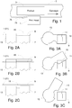
- FIGS 2A, 2B and 2C provide schematic views of part of the capping arrangement from below, and Figures 3A, 3B and 3C show schematic views of part of the capping arrangement from the front.
- a removable print cartridge 7 has a print face 9 with two rows 11 of nozzles. Each row 11 contains, for example, 150 drop-on-demand print nozzles.
- the print face 9 of the print cartridge 7 is substantially planar and is roughly in line with the front surface of the print head 1, but in practice will tend to be very slightly further back, typically by about 0.1 mm to 0.5 mm.
- the print cartridge 7 may be a standard Hewlett Packard-type HP51645A, that includes both the print face 9 and rows 11 of print nozzles and also at least one ink reservoir. The ink reservoir will be filled with a suitable ink for printing onto the products 3.
- a rotatable shutter 13 has a capping arm 15, extending sideways so as to be movable by rotation of the shutter 13, which acts as a cap for the rows 11 of nozzles on the print face 9 of the print cartridge 7.
- the shutter 13 is positioned so that the capping arm 15 extends across the print face 9, and is pressed against it, thereby capping the rows 11 of nozzles. Because of the thickness of the capping arm 15, its front surface protrudes in front of the front surface of the print head 1, and is liable to obstruct the path of products 3 if they are positioned to pass in front of the print head 1 with a spacing of less than 2.5 mm.
- the shutter 13 is partway through its movement between the closed position of Figures 2A and 3A , in which the capping arm 15 caps the nozzles of the print cartridge 7, and an open position in which the nozzles are not obstructed and print cartridge 7 is free to print.
- the shutter 13 In this intermediate position, the shutter 13 has moved forwards, further into the path of the products 3 (as can be seen in Figure 2B ). This allows the shutter 13 to rotate without the capping arm 15 sliding across the print face 9. This helps to avoid damage to the print nozzles that might otherwise occur if any part of the capping arm 15 came into sliding contact with any of the nozzles.
- the shutter 13 is in its open position, and the print cartridge 7 is free to print. In this position, the shutter 13 has rotated sufficiently that the capping arm 15 is clear of the print face 9, as can be seen in Figure 3C . Additionally, the shutter as a whole has retracted back into the print head 1, so that it is now entirely behind the front face of the print head 1 and the print face 9 of the print cartridge 7, as can be seen in Figure 2C . Accordingly, in this position the shutter 13 does not obstruct the path of the products 3 even if they pass extremely close to the print head 1 and the print face 9. This allows the "throw distance" between the print face 9 and the products 3 to be minimised, thereby improving the quality of the printing on the products 3.
- forwards can be defined by reference to the direction of movement of the ink drops that are ejected from the nozzles of the print face 9 (the ink drops move forwards as they are ejected).
- these terms can be defined by reference to the plane of the print face itself, with “forwards” and “rearwards” being directions perpendicular to the plane of the print face and “front” being the side of the print face where the capping arm 15 is positioned when it is pressed against the print face 9 to cap the nozzles.
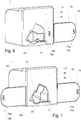
- FIG 4 shows the print head 1 with the shutter 13 in the open position
- Figure 5 shows the print head 1 with the shutter 13 in the closed position, with the print cartridge 7 removed.
- the print head 1 has a space 17 for receiving the print cartridge 7.
- the space 17 is a mount for holding the print cartridge 7, and is shaped so as to hold the print cartridge 7 securely in place in a predetermined (printing) position.
- a clip (not shown) interacts with the print cartridge 7 at or near the rear end of the print cartridge (i.e. the end remote from the print face 9 and the rows 11 of print nozzles) to prevent the print cartridge 7 from moving out of position in the space 17 during operation of the printer.
- the recess 19 is deep enough to accommodate the full thickness of the capping arm 15, so that it can move back fully behind the plane of the front surface 21 of the print head 1.
- the shutter 13 has a block 23 extending radially approximately opposite the capping arm 15.
- the shutter 13 fits in an aperture in the print head 1 that is shaped to accommodate the block 23 when the shutter 13 is in the open position, the closed position or any intermediate position. However, movement beyond the closed position of the shutter 13 is prevented by obstruction between the block 23 and a side surface 25 of the aperture in the print head.
- the print head 1 has a product ramp 73, in the form of an extension of the print head, at one side of it. This extends in the direction towards the oncoming products 3 to be printed onto.
- this extension (or a least the front face 75 thereof) is angled so that its end towards the oncoming products 3 is further back that the front surface 21 of the print head 1, and is approximately level with the edge of the conveyor 5. Therefore if any products 3 are misplaced on the conveyor 5 too close to the edge, so that they would strike the side of the print head 1, they will be caught by the front face 75 of the extension 73 which acts as a ramp to push the product 3 away from the edge of the conveyor 5 as it approaches the print head 1. In this way, the misplaced product 3 is guided so as to travel correctly past the front surface 21 of the print head 1.
- the ramp portion (ramp extension) 73 has two product sensors 77, 79 facing the conveyor 5. These detect the presence of a product 3.
- each sensor 77, 79 comprises a light source 77a, 79a (e.g. an LED) and a light detector 77b, 79b.
- a product 3 passes in front of a sensor 77, 79, light from the light source 77a 79a is reflected by the product 3 back to the light detector 77b 79b, and in this way the presence of the product 3 is detected.
- the light source 77a, 79a is modulated.
- the pattern of modulation is not important, so long as it allows light from the light source to be distinguished from other light.
- the modulation may be a steady 5 kHz. Other frequencies may be used, and complex modulation patterns may also be used if desired.
- the light from light sources 77a, 79a may be in the visible spectrum, but it is preferred to use near infra-red such as light of about 850 nm.
- the detection of a product by the sensors 77, 79 informs the printer that a product 3 is approaching, and is used by the printer to trigger a print operation. Additionally, if the rows 11 of print nozzles are capped by the shutter 13, the printer will trigger an uncapping operation. Because there are two sensors 77, 79 and they are a known distance apart in the direction of travel of products 3 on the conveyor, the printer can use the time difference between the detections of a product 3 by the two sensors to monitor the conveyor speed. The printer uses the conveyor speed information to determine how long to wait after the product 3 is detected before beginning to print, and also how quickly to print successive columns of print in order to provide the desired column spacing of the print on the product 3.
- the printer will use the sensor 77 that is further from the position of the rows 11 of print nozzles, and is more upstream with reference to the direction of travel of the products 3, to trigger a print operation and trigger an uncapping operation, as this will give the printer more time in which to respond to the detection of a product.
- the more downstream sensor 79 is normally used only for the speed measurement.
- the ramp portion 73 is detachable from the print head 1, and can be re-attached on the other side of the print head 1, so that the print head 1 can be positioned on whichever side of the conveyor 5 is desirable.
- the product sensors 77, 79 could be provided separately from the print head 1, and mounted at suitable location upstream of the print head. However, this requires the operator to perform an extra job (fixing up the sensors) when setting up the printer, and a suitable location for them on the product line has to be found. Additionally, since the printer needs to know the distance between the product sensor and the print head 1 in order to determine when to print, this distance has to be measured and entered into the printer in order for printing to be carried out properly. By attaching the product sensor to the print head 1, the set-up of the printer is considerably simplified.
- the ramp 73 could be a separate piece of equipment, fixed to in position at the edge of the conveyor at any suitable location upstream of the print head 1. However, this requires the operator to perform an extra job (fixing the ramp) when setting up the printer, and a space for it has to be found on the product line. Additionally, if the ramp 73 is to contain either or both of the product sensors 77, 79, then the distance from the print head 1 has to be entered into the printer as explained above.
- the speed of the conveyor 5 may be monitored using a shaft encoder turned by the conveyor 5.
- the shaft encoder or other speed monitor the shaft encoder or other speed monitor
- the second product sensor 79 used with the first product sensor 77 to monitor the line speed of the conveyor 5 and the products 3 on it, may be provided on or attached to the print head 1 but not on the ramp 73. It may also be provided on the far side of the print face 9 from the first product sensor 77.
- Figure 6 shows an alternative construction in which the second product sensor 79 is part of the print head 1 and not on the ramp 73.
- Figure 7 shows a further alternative, in which there are two ramps, 73, 73a, one on each side of the print head. Each ramp has a respective sensor 77, 79.
- the sensor 77 or 79 on the ramp 73 or 73a that is upstream is used to trigger the print operation and the shutter opening operation, and the two sensors 77, 79 are used together to measure the product speed.
- the ramp 73 does not have to be repositioned on the other side of the print head if the print head 1 is moved to the other side of the conveyor or if the conveyor is run in the opposite direction. Additionally, since the sensors 77, 79 are further apart, the speed of the products 3 on the conveyor can be measured more accurately.
- the printer is made substantially self-contained, and once the print head 1 has been fixed to in position at the conveyor 5 it is able to: (a) deflect products that would collide with it; (b) detect the presence of products in order to trigger print operations; and (c) to monitor the product speed, without the need for additional equipment to be mounted at the conveyor and connected to provide a signal to the printer and without the need for the operator to input the distance between the print head 1 and the product sensor 77.
Description
- The present application relates to ink jet printers and print heads therefor.
- Most ink jet printers can be divided into two types. The first type is a continuous jet printer. In a continuous ink jet printer, an ink jet runs continuously during a printing operation, and drops of ink are deflected (usually electrostatically) to direct them either to the surface that is being printed onto or alternatively to a gutter which collects drops that are not used for printing. Continuous inkjet printers are typically used for industrial printing such as printing logos, sell-by dates and other information onto cartons, food packaging, foodstuffs such as eggs, and also, for example, printing onto cabling. The second type is a drop-on-demand printer. Typically, a drop-on-demand printer has a print head with at least one row with a large number of nozzles, and an arrangement (for example a piezoelectric crystal or a heater for boiling ink) that ejects a single drop from a particular nozzle when required for printing. The nozzles and the arrangement for ejecting drops on demand may be permanent parts of the print head, or they may be part of a removable cartridge (often also including one or more ink reservoirs) that is replaced from time to time (for example when the ink reservoir or reservoirs have run out of ink). Drop-on-demand ink jet printers are typically used for printing the output of home computers.
- The solvent or solvents in the ink used in ink jet printers tends to evaporate quickly. This is necessary in order to ensure that the ink drops dry quickly during the printing operation. However, this means that if ink sits in a print head that is not being used for printing, there is a tendency for the solvent to evaporate through the print head nozzle or nozzles, with the result that the ink dries out and blocks the nozzle or nozzles. With a continuous ink jet printer, this is not a problem while the printer is operational, because the jet is running continuously. When the jet closes down, the printer may perform a special shut down sequence in which ink is sucked out of a print head and the print head is flushed with pure solvent in order to prevent any ink drying out at the nozzle. In a drop-on-demand printer, it is normal that whenever printing is not taking place, the print head is moved to a capping station just outside the range of positions at which the printer can print, and then either the print head or a cap is moved so that the cap closes over the nozzles to prevent evaporation. Additionally, the print head may discharge ink into a pad in the capping mechanism in order to dissolve and clear away any encrustations of dried ink. When the printer receives the signal to print another page, the print head is moved from the capping station back to its range of normal printing positions.
- It is also known to provide a protective cap mounted a print cartridge itself. For example,
EP 0676292 suggests that a permanent capping station may become dirty or wear out, and proposes that an ink pen may be provided with its own protective cover. InEP 0676292 , a coil of stainless steel is seated in a cavity behind and to one side of the print face having the print nozzles. At each end, the coil is attached to an arm that rotates about an axis parallel to the print face, so that rotation of the arms brings one end of the coil over the print face, forming a protective cover. -
US 5682186 proposes several capping arrangements mounted on an ink pen. In one embodiment, a cap is mounted for rotation about an axis parallel to the print face so as to flip between a closed position in which it covers the print nozzles and an open position in which the nozzles are exposed. In the open position, the cap lies next to the print face, but further back (i.e. further from the surface to be printed onto), where it does not interfere with the operation of the ink pen or printer. The cap may have a gasket, which contacts the print face in the closed position to form a protective chamber around the nozzles without the cap being in contact with the nozzles. A vent through the cap may prevent an air pressure spike within the protective chamber from forcing air into the nozzles. The cap can be driven between its open and closed positions by a motor in the printer that engages with the cap when the ink pen is at its home station. Alternatively, a spiral cam can be positioned to engage with the cap and move it into or out of its closed position as the ink pen moves towards or away from the home station. - In another embodiment,
US 5682186 proposes a cap that slides across the print face between its open and closed positions. This cap may have a gasket to form a protective seal around the nozzles. It may also have a wiper that wipes across the nozzles as the cap moves, to remove dirt, debris and accumulated ink. In a further embodiment, a page-wide printhead, with a curved print face, is provided with a cap that is arranged to move between its open and closed positions by pivoting about an axis that is parallel to the print face but behind it (i.e. further from the surface to be printed onto). The cap may have a gasket to form a protective chamber around the nozzles, and a wiper. The pivot axis may be offset from the centre of curvature of the print face so that the gasket lifts from the print face as the cap is pivoted. - It has been proposed to use a drop-on-demand printer for industrial printing, but a problem arises from the tendency of the ink to dry in the print head nozzles. In an industrial setting it may not be practical to move the print head to a capping station, either because the printer has to fit into a very small space on an industrial packing line or because it is difficult to move the print head fast enough from the capping position to the printing position in response to a signal that indicates detection of an item to be printed into, in view of the very high speed at which industrial packing lines tend to operate.
-
US 2004/0008235 proposes an arrangement in which a slidable shutter can be moved across the face of a print head or print cartridge, between a closed position in which it covers the print head and an open position in which it exposes the print head. The shutter is moved by a spring-loaded arm that extends across the conveyor carrying products to be printed onto. The spring tends to move the arm and shutter into the closed position and when a product passes down the conveyor it hits the arm and pushes it back, moving the shutter into the open position as the product moves past the print head. As soon as the product is gone, the spring moves the arm so as to bring the shutter back to the closed position. -
WO 2009/127194 proposes a closure device mounted on the front of a print head that holds a removable print cartridge, for printing onto work pieces that are conveyed past it. The closure device has a slidable cap with an opening in it. In the open position of the cap, the print face of the print cartridge (having the print nozzles) projects through the opening in the cap. This allows the print face to be very close to the work pieces. When the cap slides from the open position towards the closed position, cam surfaces move the cap towards the path of the work pieces, so that it can pass in front of the print face into the closed position. An elastomer on the cap presses against the nozzles, sealing them in the closed position. -
US 4792817 proposes an inkjet printing system in which several printheads are positioned adjacent the path of objects that are carried past the printheads on a conveyor, so that the printheads can print onto the objects. In each printhead, a plurality of nozzles are mounted in the front wall of a manifold which faces out through an opening in the forward end of a housing of the printhead. The housing has a small cross-section forward portion at the manifold, a larger cross-section rear portion and a tapered portion between the forward and rear portions. The rear portion of the housing is enlarged to provide room for solenoids that open and close the orifices of the nozzles. Each printhead is controlled by a respective printhead controller. The conveyor has a speed sensor in the form of a rotary encoder that generates pulses at a rate in accordance with the speed of the conveyor. The pulses are transmitted to the printhead controllers to provide data corresponding to the speed of the conveyor. A photocell is provided at one side of the conveyor to receive a beam of light from a reflector on the other side of the conveyor. Each object is registered by the photocell as it is fed forward, and the photocell transmits a start signal to the printhead controllers. - According to an aspect of the present invention as set out in
claim 1 there is provided an ink jet printer or a print head for an ink jet printer, the printer or print head having a printing position from which ink can be ejected for printing and the printer or print head being suitable for mounting alongside a conveyor so that the conveyor can convey products, to be printed onto, past the printing position of the printer or print head in a conveying direction, the printer or print head comprising: a ramp portion extending away from the printing position, the ramp portion being suitable to be mounted, when the printer or print head is mounted alongside a conveyor, so that it extends upstream, relative to the conveying direction, of the printing position and so that it has a ramp surface facing the conveyor, the ramp surface being angled relative to the conveying direction with (a) the end of the ramp surface that is furthest from the printing position being further sideways from the conveyor than the printing position, and (b) a place on the ramp surface spaced from the end being no further sideways from the conveyor than the printing position, whereby a product conveyed by the conveyor that strikes the ramp surface between its end and the said place will be forced sideways relative to the conveying direction as it is conveyed past the ramp surface so as to be no further sideways than the printing position before it reaches the printing position; a first sensor, for sensing the presence of a product passing the first sensor, the first sensor being mounted on the said ramp portion; and a second sensor, for sensing the presence of a product passing the second sensor, the second sensor being spaced from the first sensor in the direction from the first sensor towards the printing position. - Preferably the ramp portion is detachable. The second sensor may be between the first sensor and the printing position. In this case it may also be mounted on the ramp portion. Alternatively, the printing position may be between the first sensor and the second sensor.
- In this case, the second sensor may be mounted on a further ramp portion, extending away from the printing position, the further ramp portion being suitable to be mounted, when the printer or print head is mounted alongside a conveyor, so that it extends downstream, relative to the conveying direction, of the printing position and so that it has a ramp surface facing the conveyor, the ramp surface being angled relative to the conveying direction with (a) the end of the ramp surface that is furthest from the printing position being further sideways from the conveyor than the printing position, and (b) a place on the ramp surface spaced from the end being no further sideways from the conveyor than the printing position.
- Further aspects and optional features of the invention are set out in the claims, which are hereby incorporated into the description.
- Embodiments of the invention, given by way of non-limiting example, will be described with reference to the accompanying drawings.
-
Figure 1 shows a conveyor with a print head fitted with a capping arrangement embodying the present invention. -
Figures 2A to 2C are schematic views from below of part of the capping arrangement. -
Figures 3A to 3C are schematic views from the front of part of the capping arrangement. -
Figure 4 shows the print head with its capping shutter open. -
Figure 5 shows the print head with its capping shutter closed. -
Figure 6 shows the print head with an alternative arrangement of product sensors. -
Figure 7 shows the print head with an alternative arrangement of product ramps. -
Figure 1 shows schematically aprint head 1 of a drop-on-demand ink jet printer positioned to print onto a plurality ofproducts 3 that are carried passed theprint head 1 by aconveyor 5, which carries the products in the direction shown by the arrow. Theprint head 1 is fitted with a removable drop-on-demand print cartridge, having a print face. The print face is a substantially planar face having a plurality of ink jet nozzles on it. Typically the print face will have a large number of drop-on-demand print nozzles, arranged in one or more rows. Each drop-on-demand print nozzle is arranged to eject a drop of ink when a drop of ink is required from that nozzle for printing (i.e. a printed mark is required on theproduct 3 at a position in front of the nozzle concerned) but each nozzle does not normally eject a drop of ink when it is not required for printing. Theprint head 1 is positioned just above the edge of theconveyor 5 so thatproducts 3 pass close in front of the print face of the print cartridge in theprint head 1. Preferably, theproducts 3 pass in front of the print face with a spacing of no greater than 5 mm, since drop-on-demand printers typically are able to eject ink drops only over a very short distance. To get the best print quality, the distance between theproduct 3 and the print face may need to be 1 mm or less, for example about 0.5 mm. -
Figure 1 shows aprint head 1 at theconveyor 5, with other parts of the printer (for example control electronics and a user interface) being provided in a separate printer body (not shown) spaced further away from theconveyor 5. It is possible as an alternative to provide the entire printer at the position shown for theprint head 1 inFigure 1 , especially in the case that the printer is provided in a single body without a separate print head. Additionally, as a further alternative the printer or theseparate print head 1 may comprise a print face with print nozzles, instead of the print face and nozzles being part of a removable print cartridge. In this case, the printer or print head may nevertheless receive a removable cartridge that contains one or more ink reservoirs, even though the cartridge does not provide the print face and print nozzles. The print face and the print nozzles may be part of a removable print unit, rather than being a permanent part of theprint head 1, even in the case where the print face and the print nozzles are not part of a removable print cartridge along with one or more ink reservoirs. This allows the ink reservoirs to be replaced as they become empty, without replacing the print nozzles every time the ink cartridge is replaced, but the print unit can itself be removed and replaced if the print nozzles wear out or cease to work properly. If the print face and print nozzles are removable from the print head, such as when they are part of a removable print unit or a removable print cartridge, the print head will include a mount for holding the removable unit or cartridge in position, with the print face at the desired location relative to the front face of the print head. However, owing to slight manufacturing differences from one removable cartridge or unit to another, and the possibility that the position of a removable cartridge or unit in the mount may be slightly different from one occasion to another, the position of the print face and the nozzles may vary slightly. - Because the ink used by the printer tends to dry out very quickly, the print nozzles are sealed by a cap except when a
product 3, or a succession ofproducts 3, are being carried passed theprint head 1 by theconveyor 5. When it is detected that aproduct 3 is approaching theprint head 1, the cap is rapidly removed, to allow the printer to print onto theproduct 3. -
Figures 2A, 2B and 2C provide schematic views of part of the capping arrangement from below, andFigures 3A, 3B and 3C show schematic views of part of the capping arrangement from the front. Aremovable print cartridge 7 has aprint face 9 with tworows 11 of nozzles. Eachrow 11 contains, for example, 150 drop-on-demand print nozzles. Theprint face 9 of theprint cartridge 7 is substantially planar and is roughly in line with the front surface of theprint head 1, but in practice will tend to be very slightly further back, typically by about 0.1 mm to 0.5 mm. Theprint cartridge 7 may be a standard Hewlett Packard-type HP51645A, that includes both theprint face 9 androws 11 of print nozzles and also at least one ink reservoir. The ink reservoir will be filled with a suitable ink for printing onto theproducts 3. - A
rotatable shutter 13 has acapping arm 15, extending sideways so as to be movable by rotation of theshutter 13, which acts as a cap for therows 11 of nozzles on theprint face 9 of theprint cartridge 7. - In
Figures 2A and 3A , theshutter 13 is positioned so that thecapping arm 15 extends across theprint face 9, and is pressed against it, thereby capping therows 11 of nozzles. Because of the thickness of thecapping arm 15, its front surface protrudes in front of the front surface of theprint head 1, and is liable to obstruct the path ofproducts 3 if they are positioned to pass in front of theprint head 1 with a spacing of less than 2.5 mm. - In
Figures 2B and 3B , theshutter 13 is partway through its movement between the closed position ofFigures 2A and 3A , in which thecapping arm 15 caps the nozzles of theprint cartridge 7, and an open position in which the nozzles are not obstructed andprint cartridge 7 is free to print. In this intermediate position, theshutter 13 has moved forwards, further into the path of the products 3 (as can be seen inFigure 2B ). This allows theshutter 13 to rotate without thecapping arm 15 sliding across theprint face 9. This helps to avoid damage to the print nozzles that might otherwise occur if any part of thecapping arm 15 came into sliding contact with any of the nozzles. - In
Figures 2C and 3C , theshutter 13 is in its open position, and theprint cartridge 7 is free to print. In this position, theshutter 13 has rotated sufficiently that thecapping arm 15 is clear of theprint face 9, as can be seen inFigure 3C . Additionally, the shutter as a whole has retracted back into theprint head 1, so that it is now entirely behind the front face of theprint head 1 and theprint face 9 of theprint cartridge 7, as can be seen inFigure 2C . Accordingly, in this position theshutter 13 does not obstruct the path of theproducts 3 even if they pass extremely close to theprint head 1 and theprint face 9. This allows the "throw distance" between theprint face 9 and theproducts 3 to be minimised, thereby improving the quality of the printing on theproducts 3. - The terms "forwards", "in front" "behind", "rearwards" etc can be defined by reference to the direction of movement of the ink drops that are ejected from the nozzles of the print face 9 (the ink drops move forwards as they are ejected). Alternatively, these terms can be defined by reference to the plane of the print face itself, with "forwards" and "rearwards" being directions perpendicular to the plane of the print face and "front" being the side of the print face where the
capping arm 15 is positioned when it is pressed against theprint face 9 to cap the nozzles. - The construction of the
print head 1 and theshutter 13 will now be described in more detail. -
Figure 4 shows theprint head 1 with theshutter 13 in the open position andFigure 5 shows theprint head 1 with theshutter 13 in the closed position, with theprint cartridge 7 removed. Theprint head 1 has aspace 17 for receiving theprint cartridge 7. Thespace 17 is a mount for holding theprint cartridge 7, and is shaped so as to hold theprint cartridge 7 securely in place in a predetermined (printing) position. A clip (not shown) interacts with theprint cartridge 7 at or near the rear end of the print cartridge (i.e. the end remote from theprint face 9 and therows 11 of print nozzles) to prevent theprint cartridge 7 from moving out of position in thespace 17 during operation of the printer. Adjacent thespace 17 there is arecess 19 for accommodating thecapping arm 15 of theshutter 13 in the open position. Therecess 19 is deep enough to accommodate the full thickness of thecapping arm 15, so that it can move back fully behind the plane of thefront surface 21 of theprint head 1. - As can be seen in
Figure 4 , once theshutter 13 reaches the open position, further rotation is prevented by obstruction between the cappingarm 15 and the edge of therecess 19. Theshutter 13 has ablock 23 extending radially approximately opposite thecapping arm 15. Theshutter 13 fits in an aperture in theprint head 1 that is shaped to accommodate theblock 23 when theshutter 13 is in the open position, the closed position or any intermediate position. However, movement beyond the closed position of theshutter 13 is prevented by obstruction between theblock 23 and aside surface 25 of the aperture in the print head. - As can be seen in
Figures 4 and 5 , theprint head 1 has aproduct ramp 73, in the form of an extension of the print head, at one side of it. This extends in the direction towards the oncomingproducts 3 to be printed onto. As shown inFigure 1 , this extension (or a least thefront face 75 thereof) is angled so that its end towards the oncomingproducts 3 is further back that thefront surface 21 of theprint head 1, and is approximately level with the edge of theconveyor 5. Therefore if anyproducts 3 are misplaced on theconveyor 5 too close to the edge, so that they would strike the side of theprint head 1, they will be caught by thefront face 75 of theextension 73 which acts as a ramp to push theproduct 3 away from the edge of theconveyor 5 as it approaches theprint head 1. In this way, themisplaced product 3 is guided so as to travel correctly past thefront surface 21 of theprint head 1. - The ramp portion (ramp extension) 73 has two product sensors 77, 79 facing the
conveyor 5. These detect the presence of aproduct 3. Any convenient product sensing arrangement can be used. In the illustrated embodiment, each sensor 77, 79 comprises alight source light detector product 3 passes in front of a sensor 77, 79, light from thelight source 77aproduct 3 back to thelight detector 77bproduct 3 is detected. In order to allow thedetector light source light source light sources - The detection of a product by the sensors 77, 79 informs the printer that a
product 3 is approaching, and is used by the printer to trigger a print operation. Additionally, if therows 11 of print nozzles are capped by theshutter 13, the printer will trigger an uncapping operation. Because there are two sensors 77, 79 and they are a known distance apart in the direction of travel ofproducts 3 on the conveyor, the printer can use the time difference between the detections of aproduct 3 by the two sensors to monitor the conveyor speed. The printer uses the conveyor speed information to determine how long to wait after theproduct 3 is detected before beginning to print, and also how quickly to print successive columns of print in order to provide the desired column spacing of the print on theproduct 3. - Usually, the printer will use the sensor 77 that is further from the position of the
rows 11 of print nozzles, and is more upstream with reference to the direction of travel of theproducts 3, to trigger a print operation and trigger an uncapping operation, as this will give the printer more time in which to respond to the detection of a product. The more downstream sensor 79 is normally used only for the speed measurement. - Preferably the
ramp portion 73 is detachable from theprint head 1, and can be re-attached on the other side of theprint head 1, so that theprint head 1 can be positioned on whichever side of theconveyor 5 is desirable. - Various other arrangements of
product ramp 73 and product sensors are possible, but the arrangement used in this embodiment is convenient for the user. - The product sensors 77, 79 could be provided separately from the
print head 1, and mounted at suitable location upstream of the print head. However, this requires the operator to perform an extra job (fixing up the sensors) when setting up the printer, and a suitable location for them on the product line has to be found. Additionally, since the printer needs to know the distance between the product sensor and theprint head 1 in order to determine when to print, this distance has to be measured and entered into the printer in order for printing to be carried out properly. By attaching the product sensor to theprint head 1, the set-up of the printer is considerably simplified. - The
ramp 73 could be a separate piece of equipment, fixed to in position at the edge of the conveyor at any suitable location upstream of theprint head 1. However, this requires the operator to perform an extra job (fixing the ramp) when setting up the printer, and a space for it has to be found on the product line. Additionally, if theramp 73 is to contain either or both of the product sensors 77, 79, then the distance from theprint head 1 has to be entered into the printer as explained above. - It is also possible to use only one product sensor 77, for detecting the presence of a
product 3 and triggering a print operation, if some other arrangement is used for monitoring the product speed. For example, the speed of theconveyor 5 may be monitored using a shaft encoder turned by theconveyor 5. However, once again this requires that a separate piece of equipment (the shaft encoder or other speed monitor) is installed, and the output of the separate piece of equipment must be input to the printer so that it knows the speed of products along theconveyor 5. - The second product sensor 79, used with the first product sensor 77 to monitor the line speed of the
conveyor 5 and theproducts 3 on it, may be provided on or attached to theprint head 1 but not on theramp 73. It may also be provided on the far side of theprint face 9 from the first product sensor 77. For example,Figure 6 shows an alternative construction in which the second product sensor 79 is part of theprint head 1 and not on theramp 73.Figure 7 shows a further alternative, in which there are two ramps, 73, 73a, one on each side of the print head. Each ramp has a respective sensor 77, 79. Whichever direction theproducts 3 are carried past theprint head 1 by theconveyor 5, the sensor 77 or 79 on theramp ramp 73 does not have to be repositioned on the other side of the print head if theprint head 1 is moved to the other side of the conveyor or if the conveyor is run in the opposite direction. Additionally, since the sensors 77, 79 are further apart, the speed of theproducts 3 on the conveyor can be measured more accurately. However, the speed of an individual product cannot be measured until its leading edge has passed both of the product sensors 77, 79, and if one sensor is positioned downstream of the printing position it may not be possible to determine the speed of the product in time to use that information during the operation of printing on that product. Therefore constructions such as the one shown inFigure 7 may be used to monitor the speed of theconveyor 5, and detect changes in the conveyor speed over time, rather than to measure the speed of eachproduct 3 individually for use in the print operation on that product. - By fitting the sensor 77, for detecting the presence of
product 3, on theramp 73, and providing theramp 73 as an extension that is part of or is fixed to theprint head 1, and additionally providing a second product sensor 79, for use with the first sensor to monitor product speed, on the ramp or alternatively on the print head or fixed to it at some other position, the printer is made substantially self-contained, and once theprint head 1 has been fixed to in position at theconveyor 5 it is able to: (a) deflect products that would collide with it; (b) detect the presence of products in order to trigger print operations; and (c) to monitor the product speed, without the need for additional equipment to be mounted at the conveyor and connected to provide a signal to the printer and without the need for the operator to input the distance between theprint head 1 and the product sensor 77. - The embodiments that have been described and illustrated are provided by way of non-limiting example only, and further modifications and alternatives will be apparent to those skilled in the art.
Claims (6)
- An ink jet printer or a print head (1) for an ink jet printer, the printer or print head having a printing position from which ink can be ejected for printing and the printer or print head being suitable for mounting alongside a conveyor (5) so that the conveyor can convey products (3), to be printed onto, past the printing position of the printer or print head (1) in a conveying direction,
the printer or print head (1) comprising:a first sensor (77a, 77b), for sensing the presence of a product passing the first sensor, anda ramp portion (73) extending away from the printing position, the ramp portion (73) being suitable to be mounted in a manner, when the printer or print head (1) is mounted alongside a conveyor (5), so that it extends upstream, relative to the conveying direction, of the printing position and so that it has a ramp surface (75) facing the conveyor, the ramp surface being angled relative to the conveying direction with the end of the ramp surface (75) that is furthest from the printing position being further sideways from the conveyor (5) than the printing position,characterised in that(a) the ramp portion is such that when it is mounted in the said manner, a place on the ramp surface (75) spaced from the end is no further sideways from the conveyor (75) than the printing position, whereby a product (3) conveyed by the conveyor (5) that strikes the ramp surface (75) between its end and the said place will be forced sideways relative to the conveying direction as it is conveyed past the ramp surface so as to be no further sideways than the printing position before it reaches the printing position;(b) the first sensor is mounted on the said ramp portion (73); and(c) the printer or print head comprises a second sensor (79a, 79b), for sensing the presence of a product passing the second sensor, the second sensor being spaced from the first sensor in the direction from the first sensor towards the printing position. - A printer or print head according to claim 1 in which the ramp portion (73) is detachable.
- A printer or a print head according to claim 1 or claim 2 in which the second sensor (79a, 79b) is between the first sensor and the printing position.
- A printer or print head according to claim 3 in which the second sensor (79a, 79b) is mounted on the ramp portion (73).
- A printer or a print head according to claim 1 or claim 2 in which the printing position is between the first sensor (77a, 77b) and the second sensor (79a, 79b).
- A printer or print head according to claim 5 in which the second sensor (79a, 79b) is mounted on a further ramp portion (73a), extending away from the printing position, the further ramp portion (73a) being suitable to be mounted, when the printer or print head is mounted alongside a conveyor (5), so that it extends downstream, relative to the conveying direction, of the printing position and so that it has a ramp surface facing the conveyor, the ramp surface being angled relative to the conveying direction with (a) the end of the ramp surface that is furthest from the printing position being further sideways from the conveyor than the printing position, and (b) a place on the ramp surface spaced from the end being no further sideways from the conveyor than the printing position.
Priority Applications (1)
| Application Number | Priority Date | Filing Date | Title |
|---|---|---|---|
| EP19177426.4A EP3556563B1 (en) | 2012-09-12 | 2013-09-10 | Ink jet print head and cap |
Applications Claiming Priority (2)
| Application Number | Priority Date | Filing Date | Title |
|---|---|---|---|
| GB1216253.3A GB2505883B (en) | 2012-09-12 | 2012-09-12 | Ink jet print head and cap |
| PCT/GB2013/052366 WO2014041341A1 (en) | 2012-09-12 | 2013-09-10 | Ink jet print head and cap |
Related Child Applications (2)
| Application Number | Title | Priority Date | Filing Date |
|---|---|---|---|
| EP19177426.4A Division-Into EP3556563B1 (en) | 2012-09-12 | 2013-09-10 | Ink jet print head and cap |
| EP19177426.4A Division EP3556563B1 (en) | 2012-09-12 | 2013-09-10 | Ink jet print head and cap |
Publications (2)
| Publication Number | Publication Date |
|---|---|
| EP2895330A1 EP2895330A1 (en) | 2015-07-22 |
| EP2895330B1 true EP2895330B1 (en) | 2019-07-24 |
Family
ID=47137315
Family Applications (2)
| Application Number | Title | Priority Date | Filing Date |
|---|---|---|---|
| EP19177426.4A Active EP3556563B1 (en) | 2012-09-12 | 2013-09-10 | Ink jet print head and cap |
| EP13760110.0A Active EP2895330B1 (en) | 2012-09-12 | 2013-09-10 | Ink jet print head and cap |
Family Applications Before (1)
| Application Number | Title | Priority Date | Filing Date |
|---|---|---|---|
| EP19177426.4A Active EP3556563B1 (en) | 2012-09-12 | 2013-09-10 | Ink jet print head and cap |
Country Status (6)
| Country | Link |
|---|---|
| US (2) | US9333753B2 (en) |
| EP (2) | EP3556563B1 (en) |
| CN (2) | CN107097525B (en) |
| BR (2) | BR122021014037B1 (en) |
| GB (3) | GB2505883B (en) |
| WO (1) | WO2014041341A1 (en) |
Families Citing this family (15)
| Publication number | Priority date | Publication date | Assignee | Title |
|---|---|---|---|---|
| US9211716B2 (en) * | 2011-09-13 | 2015-12-15 | Videojet Technologies Inc. | Capping device |
| WO2016118973A1 (en) * | 2015-01-25 | 2016-07-28 | Ten Media, Llc Dba Ten Ag Tech Co. | Method protecting and maintaining laser systems and inkjet systems used for marking food products |
| US9434155B1 (en) | 2015-08-31 | 2016-09-06 | Xerox Corporation | Method and system for printhead alignment based on print medium width |
| US9782971B2 (en) * | 2015-12-07 | 2017-10-10 | The Procter & Gamble Company | Cartridge servicing cases for fluid jet cartridge |
| US11077689B2 (en) | 2015-12-07 | 2021-08-03 | The Procter & Gamble Company | Systems and methods for providing a service station routine |
| US11590782B2 (en) | 2015-12-07 | 2023-02-28 | The Procter & Gamble Company | Systems and methods for providing a service station routine |
| JP6714822B2 (en) * | 2016-01-27 | 2020-07-01 | セイコーエプソン株式会社 | Liquid ejector |
| US9566798B1 (en) * | 2016-05-24 | 2017-02-14 | Eastman Kodak Company | Inkjet printhead assembly with repositionable shutter |
| WO2020053791A1 (en) | 2018-09-11 | 2020-03-19 | Entrust Datacard Corporation | Printhead guard |
| DE102019107986A1 (en) * | 2019-03-28 | 2020-10-01 | Koenig & Bauer Ag | Printing unit |
| US10814634B1 (en) * | 2019-07-11 | 2020-10-27 | Xerox Corporation | Printhead cap for attenuating the drying of ink from a printhead during periods of printer inactivity |
| JP7171941B2 (en) * | 2019-10-31 | 2022-11-15 | 株式会社Fuji | discharge device |
| JP7432114B2 (en) * | 2020-03-31 | 2024-02-16 | ブラザー工業株式会社 | inkjet recording device |
| WO2023188190A1 (en) * | 2022-03-30 | 2023-10-05 | ローランドディー.ジー.株式会社 | Printer device |
| GB2618375A (en) * | 2022-05-05 | 2023-11-08 | Dover Europe Sarl | Printing apparatus and method of operation |
Family Cites Families (40)
| Publication number | Priority date | Publication date | Assignee | Title |
|---|---|---|---|---|
| DE2831855C2 (en) * | 1978-07-20 | 1983-10-27 | NCR Corp., 45479 Dayton, Ohio | Inkjet printing system |
| GB2055768B (en) * | 1979-07-30 | 1983-04-20 | Ricoh Kk | Automatic sheet feeding systems in printing apparatus |
| US4380967A (en) * | 1981-09-14 | 1983-04-26 | Nordson Corporation | System for automatically coating objects with a plurality of quantities of a coating material using a single discharge apparatus |
| DE3207072A1 (en) | 1982-02-26 | 1983-09-15 | Siemens AG, 1000 Berlin und 8000 München | COVER AND CLEANING DEVICE FOR INK WRITING HEADS |
| US4792817A (en) * | 1983-08-29 | 1988-12-20 | Diagraph Corporation | Ink jet printing systems |
| JPS61215060A (en) * | 1985-03-22 | 1986-09-24 | Tokyo Electric Co Ltd | Printing apparatus |
| JPS61230946A (en) * | 1985-04-08 | 1986-10-15 | Tokyo Electric Co Ltd | Printing apparatus |
| US5101224A (en) * | 1989-06-13 | 1992-03-31 | Marsh Company | Ink jet print head support |
| US5094442A (en) * | 1990-07-30 | 1992-03-10 | Xerox Corporation | Translating electronic registration system |
| JPH04166356A (en) * | 1990-10-30 | 1992-06-12 | Seiko Epson Corp | Recorder |
| US5260724A (en) * | 1991-01-09 | 1993-11-09 | Seiko Epson Corporation | Capping device for ink jet printer |
| JPH0640103A (en) * | 1992-07-24 | 1994-02-15 | Hitachi Ltd | Printer |
| US5682186A (en) * | 1994-03-10 | 1997-10-28 | Hewlett-Packard Company | Protective capping apparatus for an ink-jet pen |
| US5572245A (en) | 1994-03-10 | 1996-11-05 | Hewlett-Packard Company | Protective cover apparatus for an ink-jet pen |
| US5757395A (en) | 1995-09-25 | 1998-05-26 | Hewlett-Packard Company | Color capable single-cartridge inkjet service station |
| JPH10157245A (en) * | 1996-11-27 | 1998-06-16 | Seiko Precision Kk | Printing apparatus |
| WO1999021722A2 (en) * | 1997-10-24 | 1999-05-06 | Industrial Dynamics Co., Ltd. | Laser marking with beam deflection verification and intensity control |
| JP3912568B2 (en) * | 1997-11-07 | 2007-05-09 | ブラザー工業株式会社 | Printing device |
| JP2001010138A (en) * | 1999-06-28 | 2001-01-16 | Seiko Precision Inc | Printer |
| JP2002137405A (en) * | 2000-10-31 | 2002-05-14 | Canon Inc | Capping mechanism and ink jet recorder using the same |
| US20030076376A1 (en) * | 2001-10-23 | 2003-04-24 | Greeven John C. | Inkjet printhead with integrated sealing and wiping function |
| US6726306B2 (en) * | 2002-07-10 | 2004-04-27 | Hewlett-Packard Development Company, L.P. | Print head shutter |
| US6863459B2 (en) * | 2002-11-29 | 2005-03-08 | Brother Kogyo Kabushiki Kaisha | Medium-edge setting device and image forming apparatus |
| US7370860B2 (en) * | 2004-09-29 | 2008-05-13 | Lexmark International, Inc. | Automatic edge guide assembly using springs and tapered surfaces |
| US7284820B2 (en) * | 2004-12-06 | 2007-10-23 | Silverbrook Research Pty Ltd | Two-stage capping mechanism for inkjet printers |
| KR100782817B1 (en) * | 2005-08-29 | 2007-12-06 | 삼성전자주식회사 | Spitting device in inkjet head and inkjet image forming apparatus adopting the same |
| CN1962268A (en) * | 2005-11-11 | 2007-05-16 | 明基电通股份有限公司 | Ink-jet printing apparatus having print head protective mechanism |
| KR100667847B1 (en) * | 2005-12-23 | 2007-01-11 | 삼성전자주식회사 | Inkjet image forming apparatus |
| TWI274670B (en) * | 2006-03-21 | 2007-03-01 | Lite On Technology Corp | Driving module utilized for driving a print head maintenance station |
| JP2007283545A (en) * | 2006-04-13 | 2007-11-01 | Seiko Epson Corp | Liquid jet device |
| ES2302634B1 (en) * | 2006-11-28 | 2009-05-21 | Kerajet, S.A. | AUTONOMOUS PRINTING MODULE BY INK JET. |
| JP4975492B2 (en) | 2007-03-19 | 2012-07-11 | 株式会社リコー | Image forming apparatus |
| JP4862754B2 (en) * | 2007-06-12 | 2012-01-25 | セイコーエプソン株式会社 | Fluid ejecting apparatus and cap drive control method |
| JP2009233961A (en) * | 2008-03-26 | 2009-10-15 | Noritsu Koki Co Ltd | Inkjet printer |
| DE102008019715A1 (en) * | 2008-04-18 | 2009-10-22 | Aps Alternative Printing Services Gmbh | Closure device, printhead, artwork, method for closing a printhead, and use of the closure device |
| US20100302309A1 (en) * | 2009-05-29 | 2010-12-02 | Brother Kogyo Kabushiki Kaisha | Ink Jet Printer |
| JP5141711B2 (en) * | 2010-03-31 | 2013-02-13 | ブラザー工業株式会社 | Inkjet recording device |
| WO2011147485A1 (en) | 2010-05-27 | 2011-12-01 | Errevi S.R.L. | Apparatus for digital printing on articles constituted by containers made of sintered expanded polystryrene |
| JP5728940B2 (en) * | 2010-12-28 | 2015-06-03 | セイコーエプソン株式会社 | Liquid ejector |
| US8485637B2 (en) * | 2011-01-27 | 2013-07-16 | Eastman Kodak Company | Carriage with capping surface for inkjet printhead |
-
2012
- 2012-09-12 GB GB1216253.3A patent/GB2505883B/en active Active
- 2012-09-12 GB GB1318300.9A patent/GB2507876B/en active Active
- 2012-09-12 GB GB1318301.7A patent/GB2507877B/en active Active
-
2013
- 2013-09-10 EP EP19177426.4A patent/EP3556563B1/en active Active
- 2013-09-10 BR BR122021014037-5A patent/BR122021014037B1/en active IP Right Grant
- 2013-09-10 CN CN201611069544.9A patent/CN107097525B/en active Active
- 2013-09-10 CN CN201380047187.4A patent/CN104619502B/en active Active
- 2013-09-10 US US14/419,186 patent/US9333753B2/en active Active
- 2013-09-10 BR BR112015004590-1A patent/BR112015004590B1/en active IP Right Grant
- 2013-09-10 EP EP13760110.0A patent/EP2895330B1/en active Active
- 2013-09-10 WO PCT/GB2013/052366 patent/WO2014041341A1/en active Application Filing
-
2016
- 2016-04-07 US US15/093,096 patent/US9517627B2/en active Active
Non-Patent Citations (1)
| Title |
|---|
| None * |
Also Published As
| Publication number | Publication date |
|---|---|
| CN104619502B (en) | 2016-12-28 |
| EP2895330A1 (en) | 2015-07-22 |
| GB2505883B (en) | 2014-10-08 |
| BR112015004590B1 (en) | 2022-03-29 |
| BR112015004590A2 (en) | 2017-07-04 |
| EP3556563B1 (en) | 2023-04-19 |
| EP3556563A1 (en) | 2019-10-23 |
| CN104619502A (en) | 2015-05-13 |
| US9517627B2 (en) | 2016-12-13 |
| BR122021014037B1 (en) | 2022-08-16 |
| GB201216253D0 (en) | 2012-10-24 |
| GB2505883A (en) | 2014-03-19 |
| GB2507876A (en) | 2014-05-14 |
| US9333753B2 (en) | 2016-05-10 |
| US20150239249A1 (en) | 2015-08-27 |
| GB201318301D0 (en) | 2013-11-27 |
| GB201318300D0 (en) | 2013-11-27 |
| GB2507877A (en) | 2014-05-14 |
| CN107097525A (en) | 2017-08-29 |
| US20160236472A1 (en) | 2016-08-18 |
| CN107097525B (en) | 2019-09-10 |
| GB2507876B (en) | 2014-10-08 |
| WO2014041341A1 (en) | 2014-03-20 |
| GB2507877B (en) | 2014-10-08 |
Similar Documents
| Publication | Publication Date | Title |
|---|---|---|
| EP2895330B1 (en) | Ink jet print head and cap | |
| EP2900475B1 (en) | Drop detection | |
| EP2948312B1 (en) | Testing a printhead | |
| US20110141175A1 (en) | Position detection with two-dimensional sensor in printer | |
| US6877838B2 (en) | Detection of in-flight positions of ink droplets | |
| US6491366B1 (en) | Ink drop detector waste ink removal system | |
| EP1279507B1 (en) | Ink drop detector | |
| US20120069075A1 (en) | Optical sensor for printer media motion detection | |
| US8317292B2 (en) | Method of position detection with two-dimensional sensor in printer | |
| US7455380B2 (en) | Printing apparatus, media detection apparatus, media detection method, measurement method, computer-readable storage medium, and printing system | |
| US6454373B1 (en) | Ink drop detector waste ink removal system | |
| CN109070598B (en) | Printhead monitoring system and method | |
| JP5902654B2 (en) | Image forming apparatus | |
| JP5875325B2 (en) | Ink printer | |
| EP1490230B1 (en) | Movable ink drop detector pick up for a drop-on-demand printer | |
| EP2046580B1 (en) | Apparatus and method for controlling an ink-jet printing head through detection of light diffusion | |
| JP2004001574A (en) | Maintenance mechanism for printing head | |
| JP2008307903A5 (en) | ||
| JPH08323976A (en) | Ink spouting detection mechanism of ink-jet printing machine |
Legal Events
| Date | Code | Title | Description |
|---|---|---|---|
| PUAI | Public reference made under article 153(3) epc to a published international application that has entered the european phase |
Free format text: ORIGINAL CODE: 0009012 |
|
| 17P | Request for examination filed |
Effective date: 20150320 |
|
| AK | Designated contracting states |
Kind code of ref document: A1 Designated state(s): AL AT BE BG CH CY CZ DE DK EE ES FI FR GB GR HR HU IE IS IT LI LT LU LV MC MK MT NL NO PL PT RO RS SE SI SK SM TR |
|
| AX | Request for extension of the european patent |
Extension state: BA ME |
|
| DAX | Request for extension of the european patent (deleted) | ||
| GRAP | Despatch of communication of intention to grant a patent |
Free format text: ORIGINAL CODE: EPIDOSNIGR1 |
|
| STAA | Information on the status of an ep patent application or granted ep patent |
Free format text: STATUS: GRANT OF PATENT IS INTENDED |
|
| GRAJ | Information related to disapproval of communication of intention to grant by the applicant or resumption of examination proceedings by the epo deleted |
Free format text: ORIGINAL CODE: EPIDOSDIGR1 |
|
| INTG | Intention to grant announced |
Effective date: 20190308 |
|
| STAA | Information on the status of an ep patent application or granted ep patent |
Free format text: STATUS: REQUEST FOR EXAMINATION WAS MADE |
|
| GRAP | Despatch of communication of intention to grant a patent |
Free format text: ORIGINAL CODE: EPIDOSNIGR1 |
|
| STAA | Information on the status of an ep patent application or granted ep patent |
Free format text: STATUS: GRANT OF PATENT IS INTENDED |
|
| INTC | Intention to grant announced (deleted) | ||
| INTG | Intention to grant announced |
Effective date: 20190415 |
|
| GRAS | Grant fee paid |
Free format text: ORIGINAL CODE: EPIDOSNIGR3 |
|
| GRAA | (expected) grant |
Free format text: ORIGINAL CODE: 0009210 |
|
| STAA | Information on the status of an ep patent application or granted ep patent |
Free format text: STATUS: THE PATENT HAS BEEN GRANTED |
|
| AK | Designated contracting states |
Kind code of ref document: B1 Designated state(s): AL AT BE BG CH CY CZ DE DK EE ES FI FR GB GR HR HU IE IS IT LI LT LU LV MC MK MT NL NO PL PT RO RS SE SI SK SM TR |
|
| REG | Reference to a national code |
Ref country code: GB Ref legal event code: FG4D |
|
| REG | Reference to a national code |
Ref country code: CH Ref legal event code: EP |
|
| REG | Reference to a national code |
Ref country code: DE Ref legal event code: R096 Ref document number: 602013058197 Country of ref document: DE |
|
| REG | Reference to a national code |
Ref country code: AT Ref legal event code: REF Ref document number: 1157705 Country of ref document: AT Kind code of ref document: T Effective date: 20190815 |
|
| REG | Reference to a national code |
Ref country code: IE Ref legal event code: FG4D |
|
| REG | Reference to a national code |
Ref country code: NL Ref legal event code: MP Effective date: 20190724 |
|
| REG | Reference to a national code |
Ref country code: LT Ref legal event code: MG4D |
|
| REG | Reference to a national code |
Ref country code: AT Ref legal event code: MK05 Ref document number: 1157705 Country of ref document: AT Kind code of ref document: T Effective date: 20190724 |
|
| PG25 | Lapsed in a contracting state [announced via postgrant information from national office to epo] |
Ref country code: AT Free format text: LAPSE BECAUSE OF FAILURE TO SUBMIT A TRANSLATION OF THE DESCRIPTION OR TO PAY THE FEE WITHIN THE PRESCRIBED TIME-LIMIT Effective date: 20190724 Ref country code: NO Free format text: LAPSE BECAUSE OF FAILURE TO SUBMIT A TRANSLATION OF THE DESCRIPTION OR TO PAY THE FEE WITHIN THE PRESCRIBED TIME-LIMIT Effective date: 20191024 Ref country code: SE Free format text: LAPSE BECAUSE OF FAILURE TO SUBMIT A TRANSLATION OF THE DESCRIPTION OR TO PAY THE FEE WITHIN THE PRESCRIBED TIME-LIMIT Effective date: 20190724 Ref country code: FI Free format text: LAPSE BECAUSE OF FAILURE TO SUBMIT A TRANSLATION OF THE DESCRIPTION OR TO PAY THE FEE WITHIN THE PRESCRIBED TIME-LIMIT Effective date: 20190724 Ref country code: HR Free format text: LAPSE BECAUSE OF FAILURE TO SUBMIT A TRANSLATION OF THE DESCRIPTION OR TO PAY THE FEE WITHIN THE PRESCRIBED TIME-LIMIT Effective date: 20190724 Ref country code: BG Free format text: LAPSE BECAUSE OF FAILURE TO SUBMIT A TRANSLATION OF THE DESCRIPTION OR TO PAY THE FEE WITHIN THE PRESCRIBED TIME-LIMIT Effective date: 20191024 Ref country code: NL Free format text: LAPSE BECAUSE OF FAILURE TO SUBMIT A TRANSLATION OF THE DESCRIPTION OR TO PAY THE FEE WITHIN THE PRESCRIBED TIME-LIMIT Effective date: 20190724 Ref country code: PT Free format text: LAPSE BECAUSE OF FAILURE TO SUBMIT A TRANSLATION OF THE DESCRIPTION OR TO PAY THE FEE WITHIN THE PRESCRIBED TIME-LIMIT Effective date: 20191125 Ref country code: LT Free format text: LAPSE BECAUSE OF FAILURE TO SUBMIT A TRANSLATION OF THE DESCRIPTION OR TO PAY THE FEE WITHIN THE PRESCRIBED TIME-LIMIT Effective date: 20190724 |
|
| PG25 | Lapsed in a contracting state [announced via postgrant information from national office to epo] |
Ref country code: AL Free format text: LAPSE BECAUSE OF FAILURE TO SUBMIT A TRANSLATION OF THE DESCRIPTION OR TO PAY THE FEE WITHIN THE PRESCRIBED TIME-LIMIT Effective date: 20190724 Ref country code: ES Free format text: LAPSE BECAUSE OF FAILURE TO SUBMIT A TRANSLATION OF THE DESCRIPTION OR TO PAY THE FEE WITHIN THE PRESCRIBED TIME-LIMIT Effective date: 20190724 Ref country code: GR Free format text: LAPSE BECAUSE OF FAILURE TO SUBMIT A TRANSLATION OF THE DESCRIPTION OR TO PAY THE FEE WITHIN THE PRESCRIBED TIME-LIMIT Effective date: 20191025 Ref country code: LV Free format text: LAPSE BECAUSE OF FAILURE TO SUBMIT A TRANSLATION OF THE DESCRIPTION OR TO PAY THE FEE WITHIN THE PRESCRIBED TIME-LIMIT Effective date: 20190724 Ref country code: IS Free format text: LAPSE BECAUSE OF FAILURE TO SUBMIT A TRANSLATION OF THE DESCRIPTION OR TO PAY THE FEE WITHIN THE PRESCRIBED TIME-LIMIT Effective date: 20191124 Ref country code: RS Free format text: LAPSE BECAUSE OF FAILURE TO SUBMIT A TRANSLATION OF THE DESCRIPTION OR TO PAY THE FEE WITHIN THE PRESCRIBED TIME-LIMIT Effective date: 20190724 |
|
| PG25 | Lapsed in a contracting state [announced via postgrant information from national office to epo] |
Ref country code: TR Free format text: LAPSE BECAUSE OF FAILURE TO SUBMIT A TRANSLATION OF THE DESCRIPTION OR TO PAY THE FEE WITHIN THE PRESCRIBED TIME-LIMIT Effective date: 20190724 |
|
| PG25 | Lapsed in a contracting state [announced via postgrant information from national office to epo] |
Ref country code: RO Free format text: LAPSE BECAUSE OF FAILURE TO SUBMIT A TRANSLATION OF THE DESCRIPTION OR TO PAY THE FEE WITHIN THE PRESCRIBED TIME-LIMIT Effective date: 20190724 Ref country code: PL Free format text: LAPSE BECAUSE OF FAILURE TO SUBMIT A TRANSLATION OF THE DESCRIPTION OR TO PAY THE FEE WITHIN THE PRESCRIBED TIME-LIMIT Effective date: 20190724 Ref country code: DK Free format text: LAPSE BECAUSE OF FAILURE TO SUBMIT A TRANSLATION OF THE DESCRIPTION OR TO PAY THE FEE WITHIN THE PRESCRIBED TIME-LIMIT Effective date: 20190724 Ref country code: IT Free format text: LAPSE BECAUSE OF FAILURE TO SUBMIT A TRANSLATION OF THE DESCRIPTION OR TO PAY THE FEE WITHIN THE PRESCRIBED TIME-LIMIT Effective date: 20190724 Ref country code: EE Free format text: LAPSE BECAUSE OF FAILURE TO SUBMIT A TRANSLATION OF THE DESCRIPTION OR TO PAY THE FEE WITHIN THE PRESCRIBED TIME-LIMIT Effective date: 20190724 |
|
| PG25 | Lapsed in a contracting state [announced via postgrant information from national office to epo] |
Ref country code: CZ Free format text: LAPSE BECAUSE OF FAILURE TO SUBMIT A TRANSLATION OF THE DESCRIPTION OR TO PAY THE FEE WITHIN THE PRESCRIBED TIME-LIMIT Effective date: 20190724 Ref country code: SM Free format text: LAPSE BECAUSE OF FAILURE TO SUBMIT A TRANSLATION OF THE DESCRIPTION OR TO PAY THE FEE WITHIN THE PRESCRIBED TIME-LIMIT Effective date: 20190724 Ref country code: IS Free format text: LAPSE BECAUSE OF FAILURE TO SUBMIT A TRANSLATION OF THE DESCRIPTION OR TO PAY THE FEE WITHIN THE PRESCRIBED TIME-LIMIT Effective date: 20200224 Ref country code: SK Free format text: LAPSE BECAUSE OF FAILURE TO SUBMIT A TRANSLATION OF THE DESCRIPTION OR TO PAY THE FEE WITHIN THE PRESCRIBED TIME-LIMIT Effective date: 20190724 Ref country code: MC Free format text: LAPSE BECAUSE OF FAILURE TO SUBMIT A TRANSLATION OF THE DESCRIPTION OR TO PAY THE FEE WITHIN THE PRESCRIBED TIME-LIMIT Effective date: 20190724 |
|
| REG | Reference to a national code |
Ref country code: CH Ref legal event code: PL |
|
| REG | Reference to a national code |
Ref country code: DE Ref legal event code: R097 Ref document number: 602013058197 Country of ref document: DE |
|
| PLBE | No opposition filed within time limit |
Free format text: ORIGINAL CODE: 0009261 |
|
| STAA | Information on the status of an ep patent application or granted ep patent |
Free format text: STATUS: NO OPPOSITION FILED WITHIN TIME LIMIT |
|
| PG2D | Information on lapse in contracting state deleted |
Ref country code: IS |
|
| PG25 | Lapsed in a contracting state [announced via postgrant information from national office to epo] |
Ref country code: CH Free format text: LAPSE BECAUSE OF NON-PAYMENT OF DUE FEES Effective date: 20190930 Ref country code: IE Free format text: LAPSE BECAUSE OF NON-PAYMENT OF DUE FEES Effective date: 20190910 Ref country code: LI Free format text: LAPSE BECAUSE OF NON-PAYMENT OF DUE FEES Effective date: 20190930 Ref country code: LU Free format text: LAPSE BECAUSE OF NON-PAYMENT OF DUE FEES Effective date: 20190910 |
|
| 26N | No opposition filed |
Effective date: 20200603 |
|
| REG | Reference to a national code |
Ref country code: BE Ref legal event code: MM Effective date: 20190930 |
|
| PG25 | Lapsed in a contracting state [announced via postgrant information from national office to epo] |
Ref country code: BE Free format text: LAPSE BECAUSE OF NON-PAYMENT OF DUE FEES Effective date: 20190930 Ref country code: SI Free format text: LAPSE BECAUSE OF FAILURE TO SUBMIT A TRANSLATION OF THE DESCRIPTION OR TO PAY THE FEE WITHIN THE PRESCRIBED TIME-LIMIT Effective date: 20190724 |
|
| PG25 | Lapsed in a contracting state [announced via postgrant information from national office to epo] |
Ref country code: CY Free format text: LAPSE BECAUSE OF FAILURE TO SUBMIT A TRANSLATION OF THE DESCRIPTION OR TO PAY THE FEE WITHIN THE PRESCRIBED TIME-LIMIT Effective date: 20190724 |
|
| PG25 | Lapsed in a contracting state [announced via postgrant information from national office to epo] |
Ref country code: MT Free format text: LAPSE BECAUSE OF FAILURE TO SUBMIT A TRANSLATION OF THE DESCRIPTION OR TO PAY THE FEE WITHIN THE PRESCRIBED TIME-LIMIT Effective date: 20190724 Ref country code: HU Free format text: LAPSE BECAUSE OF FAILURE TO SUBMIT A TRANSLATION OF THE DESCRIPTION OR TO PAY THE FEE WITHIN THE PRESCRIBED TIME-LIMIT; INVALID AB INITIO Effective date: 20130910 |
|
| PG25 | Lapsed in a contracting state [announced via postgrant information from national office to epo] |
Ref country code: MK Free format text: LAPSE BECAUSE OF FAILURE TO SUBMIT A TRANSLATION OF THE DESCRIPTION OR TO PAY THE FEE WITHIN THE PRESCRIBED TIME-LIMIT Effective date: 20190724 |
|
| P01 | Opt-out of the competence of the unified patent court (upc) registered |
Effective date: 20230526 |
|
| PGFP | Annual fee paid to national office [announced via postgrant information from national office to epo] |
Ref country code: GB Payment date: 20230720 Year of fee payment: 11 |
|
| PGFP | Annual fee paid to national office [announced via postgrant information from national office to epo] |
Ref country code: FR Payment date: 20230703 Year of fee payment: 11 Ref country code: DE Payment date: 20230718 Year of fee payment: 11 |