EP2895247B1 - Subsea processing - Google Patents
Subsea processing Download PDFInfo
- Publication number
- EP2895247B1 EP2895247B1 EP13747831.9A EP13747831A EP2895247B1 EP 2895247 B1 EP2895247 B1 EP 2895247B1 EP 13747831 A EP13747831 A EP 13747831A EP 2895247 B1 EP2895247 B1 EP 2895247B1
- Authority
- EP
- European Patent Office
- Prior art keywords
- pipeline
- gas
- liquid
- outlet
- tank
- Prior art date
- Legal status (The legal status is an assumption and is not a legal conclusion. Google has not performed a legal analysis and makes no representation as to the accuracy of the status listed.)
- Active
Links
Images
Classifications
-
- E—FIXED CONSTRUCTIONS
- E21—EARTH OR ROCK DRILLING; MINING
- E21B—EARTH OR ROCK DRILLING; OBTAINING OIL, GAS, WATER, SOLUBLE OR MELTABLE MATERIALS OR A SLURRY OF MINERALS FROM WELLS
- E21B43/00—Methods or apparatus for obtaining oil, gas, water, soluble or meltable materials or a slurry of minerals from wells
- E21B43/34—Arrangements for separating materials produced by the well
- E21B43/36—Underwater separating arrangements
-
- B—PERFORMING OPERATIONS; TRANSPORTING
- B01—PHYSICAL OR CHEMICAL PROCESSES OR APPARATUS IN GENERAL
- B01D—SEPARATION
- B01D19/00—Degasification of liquids
-
- B—PERFORMING OPERATIONS; TRANSPORTING
- B01—PHYSICAL OR CHEMICAL PROCESSES OR APPARATUS IN GENERAL
- B01D—SEPARATION
- B01D19/00—Degasification of liquids
- B01D19/0036—Flash degasification
-
- B—PERFORMING OPERATIONS; TRANSPORTING
- B01—PHYSICAL OR CHEMICAL PROCESSES OR APPARATUS IN GENERAL
- B01D—SEPARATION
- B01D19/00—Degasification of liquids
- B01D19/0068—General arrangements, e.g. flowsheets
-
- E—FIXED CONSTRUCTIONS
- E21—EARTH OR ROCK DRILLING; MINING
- E21B—EARTH OR ROCK DRILLING; OBTAINING OIL, GAS, WATER, SOLUBLE OR MELTABLE MATERIALS OR A SLURRY OF MINERALS FROM WELLS
- E21B43/00—Methods or apparatus for obtaining oil, gas, water, soluble or meltable materials or a slurry of minerals from wells
- E21B43/34—Arrangements for separating materials produced by the well
-
- B—PERFORMING OPERATIONS; TRANSPORTING
- B01—PHYSICAL OR CHEMICAL PROCESSES OR APPARATUS IN GENERAL
- B01D—SEPARATION
- B01D17/00—Separation of liquids, not provided for elsewhere, e.g. by thermal diffusion
Definitions
- the fluid from the well may be multiphase, containing gas and liquid phases.
- the amount of liquid and gas, and the nature of the flow, may fluctuate.
- the compressor station configuration facilitates access to the compressor and other processing components.
- the compressor and processing components may each be provided in removable modules in the frame to facilitate replacement and/or repair.
- the apparatus has a gas pipe 4 which is connected to the stem 10 and receives gas from the pipeline through the aperture.
- the stem 10 defines a path for gas between the inside of the pipeline 2 and the gas pipe 4.
- a flow of the multiphase fluid passes through the first portion 5, and enters the tee.
- Gas escapes naturally up through the stem of the tee into the gas pipe 4 (as “separated gas”), whilst liquid from the multiphase fluid remains inside the pipeline, passes the tee and enters into the second portion 6 of the pipeline (as “separated liquid”).
- gas is tapped off automatically, as the multiphase flow is passed along the pipeline as a result the gas and liquid contents are separated.
- the second portion of the pipeline may extend over a region of the seafloor with a slope in terrain.
- the natural changes in the seafloor topography may be utilised to provide the necessary slope of the pipeline, downstream of the tee.
- the pipe may lie on a sloping part of the seabed.
- the portion 6 may slope from the tee and follow along a slope of the seabed downwards into a topographic low region in the seabed.
- the tee may be arranged at a relative high point of the seabed.
- the pipeline may be arranged such that the second portion 6 has a slope greater than the first portion.
- the first portion 5 of the pipeline may be arranged horizontally.
- the tubular body section of the pipeline defined by the arms 8, 9 of the tee may be arranged horizontally, i.e. with a longitudinal through-axis in a horizontal plane.
- the tank and/or outlet may be arranged to let liquid out of the pump at a consistent rate over time, to the pump.
- the pump speed may be controllable to control the rate of liquid out of the tank. For example, the pump speed may be controlled or varied based on the level of liquid in the tank. From the pump, the liquid is driven out of the hole along a liquid transport pipe.
- the pump and tank may be located at the seabed for example in a topographic depression.
- the gradient of the slope of the second pipe portion 6 may provide sufficient height above the pump that a significant gravity component contributes to driving the liquid flow.
- the hole 21 may be provided with a receptacle or tubular lining to define the necessary space therein for receiving the tank 18 and pump 19.
- the hole is typically open to the sea.
- Other processing components may also be provided in the hole 21.
- the tee in this case is positioned a substantial distance away from the well, such that the pipeline portion 5 upstream of the tee acts to cool the fluid in the pipeline.
- the multiphase fluid from the well may at an upstream location close to the well head, have a temperature of around 60-120 degrees Celsius.
- the temperature of the seawater surrounding the pipeline at the seabed may be around 0 to 4 degrees.
- heat is transferred from the fluid across the wall of the pipeline to the surrounding sea causing the fluid inside the pipeline to cool.
- the fluid in the pipeline may have been cooled as a result of its transport through the pipe to a temperature of around 0 to 10 degrees Celsius.
- condensed liquid may be produced from the gas, contributing to reducing liquid content in the gas.
- the pipe tee may be arranged at least 5 km from the well.
- the pipeline portion 5 may have a length of at least 5km.
- a second pipeline and optionally further pipelines, could be provided in addition to pipeline 2 and arranged similarly.
- Such a second (or each further pipeline) may be provided with a tee through a wall of the second pipeline to separate gas from the liquid, and separated gas may be supplied to a compressor and be compressed. Multiple compressors may be used.
- the compressed gas from each such pipeline may be supplied into a single trunk line 12.
- the trunk line may then act as a common transport pipeline for transporting separated and compressed gas from the different pipelines.
- Separated liquid from each pipeline may be conveyed to a pump located in a single excavation, caisson or glory hole 21.
- the hole 21 may then act as a common hole housing equipment for processing liquid from the different pipelines.
- a pipe tee provides a simple way of tapping off gas from the pipeline to separate the gas and liquid without any other modification to the pipeline than providing an outlet in the wall of the pipe and connecting the gas pipe thereto. That is, the simple presence of an outlet through the wall in the upper portion of a pipe section removes the gas flowing adjacent to or against the wall inside the pipeline. There is minimal disturbance to the flow, such that the liquid may continue from pipe portion 5 into the pipe portion 6 as a stratified fluid.
- the flow path for fluid through the pipeline portions 5, 6 and the tee is a smooth, unobstructed and/or slowly changing flow path.
- the pipeline 2 can simply consist of basic standard pipeline sections and fittings. The walls of the pipeline and/or the tee, i.e. stem and arms, keep the surrounding sea out of the pipeline and/or tee. There is no need for any internal modification to the diameter or any arrangement to stimulate the fluid or liquid inside the pipe in proximity to the outlet aperture or tee.
Landscapes
- Engineering & Computer Science (AREA)
- Mining & Mineral Resources (AREA)
- Geology (AREA)
- Life Sciences & Earth Sciences (AREA)
- Fluid Mechanics (AREA)
- Environmental & Geological Engineering (AREA)
- Physics & Mathematics (AREA)
- General Life Sciences & Earth Sciences (AREA)
- Geochemistry & Mineralogy (AREA)
- Chemical & Material Sciences (AREA)
- Chemical Kinetics & Catalysis (AREA)
- Jet Pumps And Other Pumps (AREA)
- Structures Of Non-Positive Displacement Pumps (AREA)
- Earth Drilling (AREA)
Description
- The present invention relates to subsea processing of fluid from a well.
- In well production, for example in the oil and gas production industry, it can be necessary to compress fluid from a well in order to ensure that sufficient levels of fluid are produced. Where wells are located subsea and remote distances from other facilities, it can be desirable to compress the well stream to help transport well stream fluids onward to a downstream facility, for example at the surface for example offshore or onshore.
- For this purpose, it has been proposed to install compressors subsea near the well head to compress the fluid from the well, in particular the gas phase.
- The fluid from the well may be multiphase, containing gas and liquid phases. The amount of liquid and gas, and the nature of the flow, may fluctuate.
- Prior proposed arrangements may incorporate some processing of the well fluid upstream of such compressors in order to meet compressor operational requirements. Such processing equipment may include coolers and scrubbers which may be used to reduce liquid content of the gas so that the gas meets the required specification. Liquid that is separated from the gas may be conveyed downstream separately of the gas, for example with the assistance of a liquid pump.
- In addition, it has been suggested to provide the compressor in a compressor station on the seabed. Such a compressor station may comprise a robust marine frame which houses and supports the compressor and the processing components (pump, scrubber and/or cooler).
- The compressor station configuration facilitates access to the compressor and other processing components. The compressor and processing components may each be provided in removable modules in the frame to facilitate replacement and/or repair.
- Document
WO 2006/010765 discloses a plant for separating a mixture of oil, water and gas produced from a well, having in-line separators, a compressor and pumps. - The inventors have recognised that a challenge with the conventionally proposed compression stations described above is that a significant increase in size and complexity may be required in order to cope with a large fluid output from a well. Relatively large maintenance costs can then be expected in the operational phase, and total availability to the compression station may suffer due to the complexity.
- According to a first aspect of the invention there is provided subsea apparatus for processing fluid from a well as set out in the claims appended hereto.
- According to a second aspect of the invention there is provided a method of processing fluid from a well subsea as set out in the claims appended hereto.
- Each and any of the above aspects may include further features, as set out in the claims appended hereto or in the present description.
- It will be appreciated that features mentioned in relation to any of the above aspects, whether in the claims or in the description, may be combined with each other and between the different aspects.
- There will now be described, by way of example only, embodiments of the invention with reference to the accompanying drawings, in which:
-
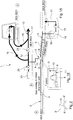
Figure 1A is a schematic representation of apparatus for processing fluid from a well in accordance with an embodiment of the disclosure; -
Figure 1B is a representation of a T-shaped pipe tee ofFigure 1A ; and -
Figure 2 is a representation of a Y-shaped pipe tee for apparatus for processing fluid, in a further embodiment. - In
Figure 1A , theapparatus 1 for processing fluid from a well is exemplified as distributed between different seabed locations A, B and C. - As seen in
Figure 1A , theapparatus 1 includes apipeline 2 which contains a flow of fluid, e.g. hydrocarbon fluid, from a well. The fluid contains liquid and gas. In proximity to atrunk line 12, a pipe tee is arranged to provide anoutlet 3 through the wall of thepipeline 2. The outlet is arranged to let gas out of thepipeline 2 to separate the gas from the liquid and produce separated gas and separate liquid. - The
pipe tee 3 can be a three-pronged or three-way tubular tee, for example a T or Y shaped tee. An example of a T-shaped tee is seen in close up in the insetFigure 1B . The tee has first and secondtubular arms tubular stem 10. The first andsecond arms second portions pipeline 2. Thearms first portion 5, thepipe tee 3, and thesecond portion 6 of thepipeline 2.Figure 2 shows an example of a Y-shaped tee 3', comprising tubular first andsecond arms 8', 9' connected to a tubular stem 10'. - The first and
second arms pipeline 2. The outlet may thus be formed through the wall in the tubular body. Thestem 10 is connected to and extends radially outwardly from the tubular body 11. - The apparatus has a gas pipe 4 which is connected to the
stem 10 and receives gas from the pipeline through the aperture. Thestem 10 defines a path for gas between the inside of thepipeline 2 and the gas pipe 4. - As seen in
Figure 1 , the tee may in practice be used in an upside-down "T" configuration, with thestem 10 arranged vertically to provide an outlet for gas from a region inside the pipe adjacent to the pipe wall, in an upper part of the pipe wall. - The multiphase fluid may typically be carried inside the pipeline in a stratified flow, in which liquid, e.g. oil, flows along a base of the pipe with gas, e.g. hydrocarbon gas, thereabove. The fluid may typically include hydrocarbon gas and hydrocarbon liquid such as oil.
- During operation, a flow of the multiphase fluid passes through the
first portion 5, and enters the tee. Gas escapes naturally up through the stem of the tee into the gas pipe 4 (as "separated gas"), whilst liquid from the multiphase fluid remains inside the pipeline, passes the tee and enters into thesecond portion 6 of the pipeline (as "separated liquid"). In this way, gas is tapped off automatically, as the multiphase flow is passed along the pipeline as a result the gas and liquid contents are separated. - The
pipeline 2 may have an internal diameter of up to around 30 inches. - Internal diameters of the first and
second arms second pipe portions second portions - In certain embodiments, the
arms stem 10 may have the same or a different internal diameter to, for example smaller or grater than, that of either of thearms - It will be appreciated that the arms of the tee may be defined by tubular sections of the first and
second portions stem 10 may be defined by a section of the gas pipe 4. - The separated gas is passed through the gas pipe 4 to
section 13 of atrunk pipeline 12. The trunk line is provided withvalves trunk line section 13 through a gas In-pipe 15 to acompressor 14 which compresses the gas. The compressed gas is conveyed from thecompressor 14 through a gas Out-pipe 16 to the trunk line, through which the compressed gas is transported to a downstream facility, e.g. an onshore or topside facility for further processing. - In other embodiments, the gas may by pass the
section 13 to enter thecompressor 14 directly. However, the arrangement shown is convenient for directing gas to the compressor when switching production from a natural flow production phase to a compression phase in which the compressor is used. In the natural phase,valve 24 is open and gas from the outlet is directed through the valve along the trunk line. In the compression phase, thevalves receiver 25 for launching or receiving pigs through the trunk line throughvalves - The
trunk pipeline 12 may have an internal diameter of up to around 50 inches. - The separated liquid passes through the
second pipeline portion 6 and is conveyed via atank 18 and pump 19 to a downstream facility (not shown). The liquid may be combined with the compressed gas in thetrunk line 12, or may be carried separately of the compressed gas to the downstream facility. - The
second portion 6 of the pipeline is sloped to help move the separated liquid under the force of gravity along the pipeline. The length and slope of thesecond portion 6 is selected so as to be able to absorb liquid slugs in the multiphase flow such that the slug flow effects on the processing system are avoided. - In practice, the
portion 6 of thepipeline 2 downstream of the tee may have a length in the range of a few tens of metres to several kilometres and may define a slope inclined at an angle from horizontal of typically 0.5 degrees or greater. - The second portion of the pipeline may extend over a region of the seafloor with a slope in terrain. The natural changes in the seafloor topography may be utilised to provide the necessary slope of the pipeline, downstream of the tee. For example, the pipe may lie on a sloping part of the seabed. The
portion 6 may slope from the tee and follow along a slope of the seabed downwards into a topographic low region in the seabed. The tee may be arranged at a relative high point of the seabed. The pipeline may be arranged such that thesecond portion 6 has a slope greater than the first portion. Thefirst portion 5 of the pipeline may be arranged horizontally. Similarly, the tubular body section of the pipeline defined by thearms - The end of the pipeline may be provided with a
pipe section 20 connecting thepipeline 2 to thetank 18. Thetank 18 is provided in ahole 21, for example an excavation, or glory hole or caisson, extending into the subsurface from the seabed. Thepump 19 is connected to the tank and is arranged to receive liquid from the tank on a continuous basis. The pump is also provided in the excavation or glory hole along with the tank. The tank receives and contains separated liquid, and may be dimensioned so as to help absorb variations of liquid content in the multiphase flow. For example, if there is a large variation of liquid content of the fluid from the well, the tank may be sized so that there is little impact on the liquid level within the tank. The tank has an outlet for liquid from the tank. The tank and/or outlet may be arranged to let liquid out of the pump at a consistent rate over time, to the pump. The pump speed may be controllable to control the rate of liquid out of the tank. For example, the pump speed may be controlled or varied based on the level of liquid in the tank. From the pump, the liquid is driven out of the hole along a liquid transport pipe. - By directing the liquid into the hole location below the seabed the influence of the force of gravity to drive liquid flow is enhanced; a difference in potential energy is generated. This facilitates onward transport of liquid, and reduces pump requirements.
- In other embodiments, the pump and tank may be located at the seabed for example in a topographic depression. In such a case, the gradient of the slope of the
second pipe portion 6 may provide sufficient height above the pump that a significant gravity component contributes to driving the liquid flow. - It can be noted that some gas may be present or be released from the flow of liquid in the tank or in the sloping
second portion 6 of thepipeline 2 downstream of the tee. Such gas will travel against the flow of liquid in thevertical pipe 20 andsecond portion 6, and escape through the outlet of the tee through the wall of the pipeline, into the gas pipe 4. The liquid in the tank provides in effect a dead-end for gas. The only outlet for gas to escape is through thepipe tee 3. - In practice, the
hole 21 may be provided with a receptacle or tubular lining to define the necessary space therein for receiving thetank 18 andpump 19. The hole is typically open to the sea. Other processing components may also be provided in thehole 21. - The tee in this case is positioned a substantial distance away from the well, such that the
pipeline portion 5 upstream of the tee acts to cool the fluid in the pipeline. The multiphase fluid from the well may at an upstream location close to the well head, have a temperature of around 60-120 degrees Celsius. The temperature of the seawater surrounding the pipeline at the seabed may be around 0 to 4 degrees. As a result, heat is transferred from the fluid across the wall of the pipeline to the surrounding sea causing the fluid inside the pipeline to cool. At the pipe tee, the fluid in the pipeline may have been cooled as a result of its transport through the pipe to a temperature of around 0 to 10 degrees Celsius. By cooling the fluid in the pipe, condensed liquid may be produced from the gas, contributing to reducing liquid content in the gas. - In order to provide sufficient cooling, the pipe tee may be arranged at least 5 km from the well. Thus, the
pipeline portion 5 may have a length of at least 5km. - In other embodiments, a second pipeline, and optionally further pipelines, could be provided in addition to
pipeline 2 and arranged similarly. Such a second (or each further pipeline) may be provided with a tee through a wall of the second pipeline to separate gas from the liquid, and separated gas may be supplied to a compressor and be compressed. Multiple compressors may be used. The compressed gas from each such pipeline may be supplied into asingle trunk line 12. The trunk line may then act as a common transport pipeline for transporting separated and compressed gas from the different pipelines. Separated liquid from each pipeline may be conveyed to a pump located in a single excavation, caisson orglory hole 21. Thehole 21 may then act as a common hole housing equipment for processing liquid from the different pipelines. The liquid from different pipes may be conveyed out of the glory hole in a common liquid transport pipe. A plurality of tanks and/or pumps may be arranged, for example as outlined above in relation to thepipeline 2, to receive and drive the flow of the separated liquid from the pipelines. - Use of a pipe tee provides a simple way of tapping off gas from the pipeline to separate the gas and liquid without any other modification to the pipeline than providing an outlet in the wall of the pipe and connecting the gas pipe thereto. That is, the simple presence of an outlet through the wall in the upper portion of a pipe section removes the gas flowing adjacent to or against the wall inside the pipeline. There is minimal disturbance to the flow, such that the liquid may continue from
pipe portion 5 into thepipe portion 6 as a stratified fluid. The flow path for fluid through thepipeline portions pipeline 2 can simply consist of basic standard pipeline sections and fittings. The walls of the pipeline and/or the tee, i.e. stem and arms, keep the surrounding sea out of the pipeline and/or tee. There is no need for any internal modification to the diameter or any arrangement to stimulate the fluid or liquid inside the pipe in proximity to the outlet aperture or tee. - The apparatus provides good separation efficiency through the outlet in the tee, to a level at which the gas exiting the pipeline at the tee is suitable for compression in a compressor. The fluid and gas is cooled in the
upstream portion 5 sufficiently to condensate liquid from the gas such that no further cooling of the gas exiting the pipeline, e.g. in a scrubber, is required before the gas enters the compressor. - Testing indicates that a high 99% by volume separation efficiency can be achieved using the arrangement described. Thus, the separated gas at entry to the compressor may have a liquid content of less than 1% by volume, in particular for gas dominant multiphase fluids from the well.
- The invention described has a number of advantages. It provides a simple and effective way of processing multiphase fluid from wells, in particular at a subsea hub where long distance pipelines from satellite wells meet for onward transport in large diameter common trunk lines, in particular where there are large capacity requirements. Subsea compression stations and modules can be reduced in size and made less complex. For example:
- 1) Routing liquid on a route which does not pass through the compression station for processing by a separate pump, reduces or eliminates the need for liquid handling tanks and pumps on the compression station;
- 2) The efficiency of separation of the tee is significant, and reduces or eliminates the need for further separation equipment or scrubbers upstream of the compressor; and
- 3) The use of the pipeline for cooling upstream, reduces or eliminates the need for further cooling equipment upstream of the compressor.
- Other advantages may be apparent from reading the description.
- It will be appreciated that the term "subsea" should be understood to include usage in land locked or partially land locked seas, such as lakes, fjords or estuarine channels, in addition to open seas and oceans whether containing salt water or fresh water, or mixtures thereof. The term "seabed" has a meaning accordingly.
- Various modifications and improvements may be made without departing from the scope of the invention as defined by the appended claims.
Claims (9)
- Subsea apparatus for processing fluid from a well, the apparatus comprising:a pipeline (2) arranged to contain a flow of said fluid, said fluid comprising liquid and gas;an outlet (3) extending through a wall of said pipeline, said outlet (3) arranged to let gas out of the pipeline through the outlet to separate said gas from said liquid and produce separated gas and separated liquid, wherein the pipeline is adapted to cool said fluid from the well in a portion of said pipeline upstream of the outlet by transferring heat from the fluid across the wall of the pipeline to the surrounding sea;a compressor (14) arranged to receive gas from said outlet (3) and arranged to compress the separated gas;a tank (18), wherein a portion (6) of the pipeline downstream of said outlet is arranged to receive said separated liquid, and wherein said portion (6) of the pipeline is sloped over at least part of its length, wherein said portion (6) slopes from the outlet downwards towards the tank (18), wherein the tank is arranged to receive fluid from said portion (6) of the pipeline, wherein the tank is placed below the outlet and wherein, in use, the liquid in the tank provides a dead-end for gas such that gas travels upwards against the flow of liquid to the outlet;a pump (19) arranged to receive separated liquid from said tank and pump said separated liquid in order to move the liquid to a facility located downstream of the pump, wherein said tank is arranged upstream of said pump.
- Subsea apparatus as claimed in claim 1, wherein the pipeline has a pipe tee (3) defining said outlet.
- Subsea apparatus as claimed in claim 2, wherein the pipe tee has a stem (10) and first (8) and second (9) arms connected to and extending from the stem, the arms defining a tubular section of the pipeline and the stem defining said outlet for said gas.
- Subsea apparatus as claimed in claim 3,
wherein the stem (10) is substantially perpendicular to the arms to define a T-shaped pipe tee, or wherein the stem is non-perpendicular with respect to at least one of the first (8) and second (9) arms and is generally Y-shaped, and
wherein the pipe tee is arranged with the stem extending substantially vertically in use. - Subsea apparatus as claimed in claim 1, wherein said pump and/or tank is arranged to be located in a structure formed at the seabed comprising a hole extending from the seabed into the subsurface.
- Subsea apparatus as claimed claim 1, further comprising a marine frame arranged to be located on the seabed to support the compressor (14) arranged to convey the separated liquid along a route which does not pass through the frame for supporting the compressor.
- Subsea apparatus as claimed in any preceding claim, wherein said compressor (14) is arranged to deliver compressed gas into a transport pipeline for transporting the compressed gas to the facility located downstream, said transport pipeline having an internal diameter in the range of around 40 to 50 inches, 1.02 to 1.27 metres.
- A method of subsea processing of fluid from a well, the method comprising the steps of:a. providing a pipeline (2) subsea, said pipeline having an outlet (3) through a wall; cooling the fluid in a section of the pipeline upstream of the outlet by transferring heat from the liquid across the wall of the pipeline to the surrounding sea; wherein a portion (6) of the pipeline downstream of said outlet is arranged to receive separated liquid, and wherein said portion (6) of the pipeline is sloped over at least part of its length, wherein said portion (6) slopes from the outlet downwards towards a tank (18), wherein a pump (19) is provided downstream of the tank, wherein said pipeline is located at or on the seabed, and the sloped portion slopes in a downstream direction between a first point along the pipeline and a second point along the pipeline, and the seabed is lower at the second point than at the first point; and wherein at the second point, a topographic depression is present at the seabed, providing the tank within the topographic depression;b. containing a flow of said fluid inside the pipeline;c. letting gas out of the pipeline through the outlet to separate said gas from said liquid to produce separated gas and separated liquid, letting gas travel upwards through said portion (6) of the pipeline against the flow of liquid to the outlet; andd. compressing said separated gase. receiving separated liquid in the tank (18)f pumping the separated liquid to move the liquid to a facility located downstream of the pump.
- A method as claimed in claim 8 using the apparatus of any of claims 1 to 7.
Applications Claiming Priority (2)
| Application Number | Priority Date | Filing Date | Title |
|---|---|---|---|
| GB1213953.1A GB2504695B (en) | 2012-08-06 | 2012-08-06 | Subsea processing |
| PCT/EP2013/066503 WO2014023743A2 (en) | 2012-08-06 | 2013-08-06 | Subsea processing |
Publications (2)
| Publication Number | Publication Date |
|---|---|
| EP2895247A2 EP2895247A2 (en) | 2015-07-22 |
| EP2895247B1 true EP2895247B1 (en) | 2019-12-25 |
Family
ID=46934911
Family Applications (1)
| Application Number | Title | Priority Date | Filing Date |
|---|---|---|---|
| EP13747831.9A Active EP2895247B1 (en) | 2012-08-06 | 2013-08-06 | Subsea processing |
Country Status (10)
| Country | Link |
|---|---|
| US (1) | US9790778B2 (en) |
| EP (1) | EP2895247B1 (en) |
| AU (1) | AU2013301553B2 (en) |
| BR (1) | BR112015002575B1 (en) |
| CA (1) | CA2881066C (en) |
| GB (1) | GB2504695B (en) |
| MX (1) | MX357053B (en) |
| NZ (1) | NZ705596A (en) |
| RU (1) | RU2643965C2 (en) |
| WO (1) | WO2014023743A2 (en) |
Families Citing this family (4)
| Publication number | Priority date | Publication date | Assignee | Title |
|---|---|---|---|---|
| GB2522863A (en) * | 2014-02-05 | 2015-08-12 | Statoil Petroleum As | Subsea processing |
| US10583373B2 (en) * | 2016-12-06 | 2020-03-10 | Fluidsep As | Method and device for separation of liquids and gas with use of inclined and rounded holes or channels in the wall of a pipe |
| CN106938152B (en) * | 2017-03-29 | 2018-10-16 | 青岛理工大学 | Inclined tube type underwater pre-dewatering and degassing separation device |
| CN117127945B (en) * | 2023-09-19 | 2024-01-30 | 青岛海洋地质研究所 | Efficient collection device and collection method for marine natural gas hydrate |
Family Cites Families (26)
| Publication number | Priority date | Publication date | Assignee | Title |
|---|---|---|---|---|
| US4147454A (en) * | 1975-10-23 | 1979-04-03 | Nor-Am Resources Technology Incorporated | Method of and apparatus for construction of pipes for marine use, as for ocean mining and the like |
| AU592748B2 (en) * | 1984-05-22 | 1990-01-25 | John B Lincoln | Pipeline jetting/mechanical trenching sled |
| DE3810951A1 (en) * | 1988-03-31 | 1989-10-12 | Klein Schanzlin & Becker Ag | METHOD AND DEVICE FOR GENERATING ENERGY FROM OIL SOURCES |
| US5505502A (en) * | 1993-06-09 | 1996-04-09 | Shell Oil Company | Multiple-seal underwater pipe-riser connector |
| GB9512513D0 (en) * | 1995-06-20 | 1995-08-23 | Guest John D | Improvements in or relating to T-connectors |
| FR2748293B1 (en) * | 1996-05-03 | 1998-06-19 | Coflexip | OIL EXPLOITATION INSTALLATION INCORPORATING MANIFOLD SUPPORT BASES, BASE AND METHOD OF LAYING |
| GB2317222B (en) | 1996-09-04 | 1998-11-25 | Babcock & Wilcox Co | Heat pipe heat exchangers for subsea pipelines |
| US6502635B1 (en) * | 2001-06-20 | 2003-01-07 | Chevron U.S.A. Inc. | Sub-sea membrane separation system with temperature control |
| NO321342B1 (en) * | 2001-07-20 | 2006-05-02 | Vetco Aibel As | Device for pipeline deflection |
| NO316840B1 (en) * | 2002-08-16 | 2004-05-24 | Norsk Hydro As | Rudder separator for separation of fluid, especially oil, gas and water |
| DE10310002B3 (en) * | 2003-02-27 | 2004-09-16 | Deutsches Zentrum für Luft- und Raumfahrt e.V. | Separating method, for separating liquid and gas from two-phase mixture, involves adjusting feed parameters so that layer flow, wave flow or annular flow is present in branch |
| NO321304B1 (en) * | 2003-09-12 | 2006-04-24 | Kvaerner Oilfield Prod As | Underwater compressor station |
| BRPI0513779A (en) * | 2004-07-27 | 2008-05-13 | Shell Int Research | facility to separate a mixture of oil, water and gas produced from a well |
| US7025533B1 (en) * | 2004-09-21 | 2006-04-11 | Kellogg Brown & Root, Inc. | Concentrated buoyancy subsea pipeline apparatus and method |
| US7963721B2 (en) * | 2004-09-21 | 2011-06-21 | Kellogg Brown & Root Llc | Distributed buoyancy subsea pipeline apparatus and method |
| WO2006058000A1 (en) * | 2004-11-24 | 2006-06-01 | Shell Internationale Research Maatschappij B.V. | Separator for multi-phase slug flow and method of designing same |
| NO329480B1 (en) * | 2005-03-16 | 2010-10-25 | Norsk Hydro As | Device by a rudder separator |
| US20090297271A1 (en) * | 2005-03-17 | 2009-12-03 | Hummert George T | Turf Playing Surface Aeration and Drainage System |
| US7464734B2 (en) * | 2005-08-08 | 2008-12-16 | Xuejie Liu | Self-cooling pipeline system and method for transfer of cryogenic fluids |
| WO2007071664A1 (en) * | 2005-12-21 | 2007-06-28 | Shell Internationale Research Maatschappij B.V. | System and method for separating a fluid stream |
| DE102006002242A1 (en) * | 2006-01-17 | 2007-07-19 | Linde Ag | Slug catcher, for separating gas and liquid phases of medium transported in pipeline, comprises tube with inlet, gas outlet and liquid outlet openings and fold(s) to reduce space requirement |
| US8066077B2 (en) * | 2007-12-17 | 2011-11-29 | Baker Hughes Incorporated | Electrical submersible pump and gas compressor |
| NO332062B1 (en) * | 2008-02-28 | 2012-06-11 | Statoilhydro Asa | Assembly for separating a multiphase stream |
| CN201415071Y (en) * | 2009-06-18 | 2010-03-03 | 中芯国际集成电路制造(上海)有限公司 | Pipeline component for gas-liquid separation |
| FR2952671B1 (en) * | 2009-11-17 | 2011-12-09 | Saipem Sa | INSTALLATION OF FUND-SURFACE CONNECTIONS DISPOSED IN EVENTAIL |
| BR112016019671B1 (en) * | 2014-03-12 | 2020-01-07 | Exxonmobil Upstream Research Company | Submarine multiphase separation system and method for separating oil, water, and solid particles in a multiphase fluid |
-
2012
- 2012-08-06 GB GB1213953.1A patent/GB2504695B/en active Active
-
2013
- 2013-08-06 BR BR112015002575-7A patent/BR112015002575B1/en active IP Right Grant
- 2013-08-06 US US14/419,867 patent/US9790778B2/en active Active
- 2013-08-06 AU AU2013301553A patent/AU2013301553B2/en active Active
- 2013-08-06 EP EP13747831.9A patent/EP2895247B1/en active Active
- 2013-08-06 RU RU2015106440A patent/RU2643965C2/en active
- 2013-08-06 NZ NZ705596A patent/NZ705596A/en not_active IP Right Cessation
- 2013-08-06 WO PCT/EP2013/066503 patent/WO2014023743A2/en not_active Ceased
- 2013-08-06 MX MX2015001743A patent/MX357053B/en active IP Right Grant
- 2013-08-06 CA CA2881066A patent/CA2881066C/en active Active
Non-Patent Citations (1)
| Title |
|---|
| None * |
Also Published As
| Publication number | Publication date |
|---|---|
| BR112015002575A8 (en) | 2021-08-17 |
| RU2643965C2 (en) | 2018-02-06 |
| AU2013301553A1 (en) | 2015-03-05 |
| RU2015106440A (en) | 2016-09-27 |
| WO2014023743A3 (en) | 2014-10-30 |
| EP2895247A2 (en) | 2015-07-22 |
| WO2014023743A2 (en) | 2014-02-13 |
| CA2881066A1 (en) | 2014-02-13 |
| US9790778B2 (en) | 2017-10-17 |
| BR112015002575A2 (en) | 2018-05-22 |
| GB2504695B (en) | 2018-05-30 |
| GB2504695A (en) | 2014-02-12 |
| MX357053B (en) | 2018-06-25 |
| MX2015001743A (en) | 2015-10-09 |
| NZ705596A (en) | 2017-04-28 |
| GB201213953D0 (en) | 2012-09-19 |
| BR112015002575B1 (en) | 2021-09-28 |
| AU2013301553B2 (en) | 2018-01-18 |
| US20150204180A1 (en) | 2015-07-23 |
| CA2881066C (en) | 2021-03-23 |
Similar Documents
| Publication | Publication Date | Title |
|---|---|---|
| RU2448245C1 (en) | Separation and collection of multi-phase flow fluids | |
| CA3008372C (en) | Submerged hydrocarbon recovery apparatus | |
| US20160348490A1 (en) | Subsea processing | |
| US20250215773A1 (en) | Drain Apparatus for a Subsea Pipeline | |
| US11577180B2 (en) | Subsea processing of crude oil | |
| BRPI0714011A2 (en) | system for producing oil and heavier gas fraction from a seabed reservoir, method for producing oil and heavier gas fractions from a seabed reservoir, and, vessel | |
| US20080272059A1 (en) | System and Method for Separating a Fluid Stream | |
| CA2881066C (en) | Subsea processing | |
| US11598193B2 (en) | Subsea processing of crude oil | |
| CN102428244B (en) | Method and device for protecting flexible risers | |
| WO2005040670A1 (en) | Method and system for reducing liquid accumulation in a multiphase flow pipeline | |
| GB2554076A (en) | Subsea hydrocarbon processing | |
| BR112019019329B1 (en) | SUBSEA PRODUCTION UNIT FOR SUBSEA OIL TREATMENT AND METHOD OF SEPARATION OF FLUIDS FROM A WELL STREAM CONTAINING MULTIPHASE OIL | |
| OA19026A (en) | A drain apparatus for a subsea pipeline | |
| NZ791631A (en) | A drain apparatus for a subsea pipeline |
Legal Events
| Date | Code | Title | Description |
|---|---|---|---|
| PUAI | Public reference made under article 153(3) epc to a published international application that has entered the european phase |
Free format text: ORIGINAL CODE: 0009012 |
|
| 17P | Request for examination filed |
Effective date: 20150218 |
|
| AK | Designated contracting states |
Kind code of ref document: A2 Designated state(s): AL AT BE BG CH CY CZ DE DK EE ES FI FR GB GR HR HU IE IS IT LI LT LU LV MC MK MT NL NO PL PT RO RS SE SI SK SM TR |
|
| AX | Request for extension of the european patent |
Extension state: BA ME |
|
| DAX | Request for extension of the european patent (deleted) | ||
| STAA | Information on the status of an ep patent application or granted ep patent |
Free format text: STATUS: EXAMINATION IS IN PROGRESS |
|
| 17Q | First examination report despatched |
Effective date: 20170328 |
|
| RAP1 | Party data changed (applicant data changed or rights of an application transferred) |
Owner name: EQUINOR ENERGY AS |
|
| GRAP | Despatch of communication of intention to grant a patent |
Free format text: ORIGINAL CODE: EPIDOSNIGR1 |
|
| STAA | Information on the status of an ep patent application or granted ep patent |
Free format text: STATUS: GRANT OF PATENT IS INTENDED |
|
| INTG | Intention to grant announced |
Effective date: 20190703 |
|
| GRAS | Grant fee paid |
Free format text: ORIGINAL CODE: EPIDOSNIGR3 |
|
| GRAA | (expected) grant |
Free format text: ORIGINAL CODE: 0009210 |
|
| STAA | Information on the status of an ep patent application or granted ep patent |
Free format text: STATUS: THE PATENT HAS BEEN GRANTED |
|
| RBV | Designated contracting states (corrected) |
Designated state(s): AL AT BE BG CH CY CZ DE DK EE ES FI FR GR HR HU IE IS IT LI LT LU LV MC MK MT NL NO PL PT RO RS SE SI SK SM TR |
|
| RIN1 | Information on inventor provided before grant (corrected) |
Inventor name: GUNNEROED, TOR ARNE Inventor name: BAKKE, WILLIAM Inventor name: HOLM, HENNING |
|
| AK | Designated contracting states |
Kind code of ref document: B1 Designated state(s): AL AT BE BG CH CY CZ DE DK EE ES FI FR GR HR HU IE IS IT LI LT LU LV MC MK MT NL NO PL PT RO RS SE SI SK SM TR |
|
| REG | Reference to a national code |
Ref country code: CH Ref legal event code: EP |
|
| REG | Reference to a national code |
Ref country code: DE Ref legal event code: R096 Ref document number: 602013064354 Country of ref document: DE |
|
| REG | Reference to a national code |
Ref country code: AT Ref legal event code: REF Ref document number: 1216531 Country of ref document: AT Kind code of ref document: T Effective date: 20200115 |
|
| REG | Reference to a national code |
Ref country code: IE Ref legal event code: FG4D |
|
| REG | Reference to a national code |
Ref country code: NO Ref legal event code: T2 Effective date: 20191225 |
|
| REG | Reference to a national code |
Ref country code: NL Ref legal event code: MP Effective date: 20191225 |
|
| PG25 | Lapsed in a contracting state [announced via postgrant information from national office to epo] |
Ref country code: LV Free format text: LAPSE BECAUSE OF FAILURE TO SUBMIT A TRANSLATION OF THE DESCRIPTION OR TO PAY THE FEE WITHIN THE PRESCRIBED TIME-LIMIT Effective date: 20191225 Ref country code: SE Free format text: LAPSE BECAUSE OF FAILURE TO SUBMIT A TRANSLATION OF THE DESCRIPTION OR TO PAY THE FEE WITHIN THE PRESCRIBED TIME-LIMIT Effective date: 20191225 Ref country code: BG Free format text: LAPSE BECAUSE OF FAILURE TO SUBMIT A TRANSLATION OF THE DESCRIPTION OR TO PAY THE FEE WITHIN THE PRESCRIBED TIME-LIMIT Effective date: 20200325 Ref country code: FI Free format text: LAPSE BECAUSE OF FAILURE TO SUBMIT A TRANSLATION OF THE DESCRIPTION OR TO PAY THE FEE WITHIN THE PRESCRIBED TIME-LIMIT Effective date: 20191225 Ref country code: LT Free format text: LAPSE BECAUSE OF FAILURE TO SUBMIT A TRANSLATION OF THE DESCRIPTION OR TO PAY THE FEE WITHIN THE PRESCRIBED TIME-LIMIT Effective date: 20191225 Ref country code: GR Free format text: LAPSE BECAUSE OF FAILURE TO SUBMIT A TRANSLATION OF THE DESCRIPTION OR TO PAY THE FEE WITHIN THE PRESCRIBED TIME-LIMIT Effective date: 20200326 |
|
| REG | Reference to a national code |
Ref country code: LT Ref legal event code: MG4D |
|
| PG25 | Lapsed in a contracting state [announced via postgrant information from national office to epo] |
Ref country code: RS Free format text: LAPSE BECAUSE OF FAILURE TO SUBMIT A TRANSLATION OF THE DESCRIPTION OR TO PAY THE FEE WITHIN THE PRESCRIBED TIME-LIMIT Effective date: 20191225 Ref country code: HR Free format text: LAPSE BECAUSE OF FAILURE TO SUBMIT A TRANSLATION OF THE DESCRIPTION OR TO PAY THE FEE WITHIN THE PRESCRIBED TIME-LIMIT Effective date: 20191225 |
|
| PG25 | Lapsed in a contracting state [announced via postgrant information from national office to epo] |
Ref country code: AL Free format text: LAPSE BECAUSE OF FAILURE TO SUBMIT A TRANSLATION OF THE DESCRIPTION OR TO PAY THE FEE WITHIN THE PRESCRIBED TIME-LIMIT Effective date: 20191225 |
|
| PG25 | Lapsed in a contracting state [announced via postgrant information from national office to epo] |
Ref country code: RO Free format text: LAPSE BECAUSE OF FAILURE TO SUBMIT A TRANSLATION OF THE DESCRIPTION OR TO PAY THE FEE WITHIN THE PRESCRIBED TIME-LIMIT Effective date: 20191225 Ref country code: CZ Free format text: LAPSE BECAUSE OF FAILURE TO SUBMIT A TRANSLATION OF THE DESCRIPTION OR TO PAY THE FEE WITHIN THE PRESCRIBED TIME-LIMIT Effective date: 20191225 Ref country code: PT Free format text: LAPSE BECAUSE OF FAILURE TO SUBMIT A TRANSLATION OF THE DESCRIPTION OR TO PAY THE FEE WITHIN THE PRESCRIBED TIME-LIMIT Effective date: 20200520 Ref country code: NL Free format text: LAPSE BECAUSE OF FAILURE TO SUBMIT A TRANSLATION OF THE DESCRIPTION OR TO PAY THE FEE WITHIN THE PRESCRIBED TIME-LIMIT Effective date: 20191225 Ref country code: EE Free format text: LAPSE BECAUSE OF FAILURE TO SUBMIT A TRANSLATION OF THE DESCRIPTION OR TO PAY THE FEE WITHIN THE PRESCRIBED TIME-LIMIT Effective date: 20191225 |
|
| PG25 | Lapsed in a contracting state [announced via postgrant information from national office to epo] |
Ref country code: SK Free format text: LAPSE BECAUSE OF FAILURE TO SUBMIT A TRANSLATION OF THE DESCRIPTION OR TO PAY THE FEE WITHIN THE PRESCRIBED TIME-LIMIT Effective date: 20191225 Ref country code: IS Free format text: LAPSE BECAUSE OF FAILURE TO SUBMIT A TRANSLATION OF THE DESCRIPTION OR TO PAY THE FEE WITHIN THE PRESCRIBED TIME-LIMIT Effective date: 20200425 Ref country code: SM Free format text: LAPSE BECAUSE OF FAILURE TO SUBMIT A TRANSLATION OF THE DESCRIPTION OR TO PAY THE FEE WITHIN THE PRESCRIBED TIME-LIMIT Effective date: 20191225 |
|
| REG | Reference to a national code |
Ref country code: DE Ref legal event code: R097 Ref document number: 602013064354 Country of ref document: DE |
|
| PG25 | Lapsed in a contracting state [announced via postgrant information from national office to epo] |
Ref country code: ES Free format text: LAPSE BECAUSE OF FAILURE TO SUBMIT A TRANSLATION OF THE DESCRIPTION OR TO PAY THE FEE WITHIN THE PRESCRIBED TIME-LIMIT Effective date: 20191225 Ref country code: DK Free format text: LAPSE BECAUSE OF FAILURE TO SUBMIT A TRANSLATION OF THE DESCRIPTION OR TO PAY THE FEE WITHIN THE PRESCRIBED TIME-LIMIT Effective date: 20191225 |
|
| PLBE | No opposition filed within time limit |
Free format text: ORIGINAL CODE: 0009261 |
|
| STAA | Information on the status of an ep patent application or granted ep patent |
Free format text: STATUS: NO OPPOSITION FILED WITHIN TIME LIMIT |
|
| REG | Reference to a national code |
Ref country code: AT Ref legal event code: MK05 Ref document number: 1216531 Country of ref document: AT Kind code of ref document: T Effective date: 20191225 |
|
| PG25 | Lapsed in a contracting state [announced via postgrant information from national office to epo] |
Ref country code: SI Free format text: LAPSE BECAUSE OF FAILURE TO SUBMIT A TRANSLATION OF THE DESCRIPTION OR TO PAY THE FEE WITHIN THE PRESCRIBED TIME-LIMIT Effective date: 20191225 |
|
| 26N | No opposition filed |
Effective date: 20200928 |
|
| PG25 | Lapsed in a contracting state [announced via postgrant information from national office to epo] |
Ref country code: IT Free format text: LAPSE BECAUSE OF FAILURE TO SUBMIT A TRANSLATION OF THE DESCRIPTION OR TO PAY THE FEE WITHIN THE PRESCRIBED TIME-LIMIT Effective date: 20191225 Ref country code: AT Free format text: LAPSE BECAUSE OF FAILURE TO SUBMIT A TRANSLATION OF THE DESCRIPTION OR TO PAY THE FEE WITHIN THE PRESCRIBED TIME-LIMIT Effective date: 20191225 |
|
| PG25 | Lapsed in a contracting state [announced via postgrant information from national office to epo] |
Ref country code: PL Free format text: LAPSE BECAUSE OF FAILURE TO SUBMIT A TRANSLATION OF THE DESCRIPTION OR TO PAY THE FEE WITHIN THE PRESCRIBED TIME-LIMIT Effective date: 20191225 |
|
| REG | Reference to a national code |
Ref country code: DE Ref legal event code: R119 Ref document number: 602013064354 Country of ref document: DE |
|
| PG25 | Lapsed in a contracting state [announced via postgrant information from national office to epo] |
Ref country code: MC Free format text: LAPSE BECAUSE OF FAILURE TO SUBMIT A TRANSLATION OF THE DESCRIPTION OR TO PAY THE FEE WITHIN THE PRESCRIBED TIME-LIMIT Effective date: 20191225 |
|
| REG | Reference to a national code |
Ref country code: CH Ref legal event code: PL |
|
| PG25 | Lapsed in a contracting state [announced via postgrant information from national office to epo] |
Ref country code: LU Free format text: LAPSE BECAUSE OF NON-PAYMENT OF DUE FEES Effective date: 20200806 Ref country code: CH Free format text: LAPSE BECAUSE OF NON-PAYMENT OF DUE FEES Effective date: 20200831 Ref country code: LI Free format text: LAPSE BECAUSE OF NON-PAYMENT OF DUE FEES Effective date: 20200831 |
|
| REG | Reference to a national code |
Ref country code: BE Ref legal event code: MM Effective date: 20200831 |
|
| PG25 | Lapsed in a contracting state [announced via postgrant information from national office to epo] |
Ref country code: FR Free format text: LAPSE BECAUSE OF NON-PAYMENT OF DUE FEES Effective date: 20200831 Ref country code: DE Free format text: LAPSE BECAUSE OF NON-PAYMENT OF DUE FEES Effective date: 20210302 |
|
| PG25 | Lapsed in a contracting state [announced via postgrant information from national office to epo] |
Ref country code: BE Free format text: LAPSE BECAUSE OF NON-PAYMENT OF DUE FEES Effective date: 20200831 Ref country code: IE Free format text: LAPSE BECAUSE OF NON-PAYMENT OF DUE FEES Effective date: 20200806 |
|
| PG25 | Lapsed in a contracting state [announced via postgrant information from national office to epo] |
Ref country code: TR Free format text: LAPSE BECAUSE OF FAILURE TO SUBMIT A TRANSLATION OF THE DESCRIPTION OR TO PAY THE FEE WITHIN THE PRESCRIBED TIME-LIMIT Effective date: 20191225 Ref country code: MT Free format text: LAPSE BECAUSE OF FAILURE TO SUBMIT A TRANSLATION OF THE DESCRIPTION OR TO PAY THE FEE WITHIN THE PRESCRIBED TIME-LIMIT Effective date: 20191225 Ref country code: CY Free format text: LAPSE BECAUSE OF FAILURE TO SUBMIT A TRANSLATION OF THE DESCRIPTION OR TO PAY THE FEE WITHIN THE PRESCRIBED TIME-LIMIT Effective date: 20191225 |
|
| PG25 | Lapsed in a contracting state [announced via postgrant information from national office to epo] |
Ref country code: MK Free format text: LAPSE BECAUSE OF FAILURE TO SUBMIT A TRANSLATION OF THE DESCRIPTION OR TO PAY THE FEE WITHIN THE PRESCRIBED TIME-LIMIT Effective date: 20191225 |
|
| P01 | Opt-out of the competence of the unified patent court (upc) registered |
Effective date: 20230525 |
|
| PGFP | Annual fee paid to national office [announced via postgrant information from national office to epo] |
Ref country code: NO Payment date: 20250819 Year of fee payment: 13 |