EP2895113B1 - Shoulder prosthesis - Google Patents
Shoulder prosthesis Download PDFInfo
- Publication number
- EP2895113B1 EP2895113B1 EP13810962.4A EP13810962A EP2895113B1 EP 2895113 B1 EP2895113 B1 EP 2895113B1 EP 13810962 A EP13810962 A EP 13810962A EP 2895113 B1 EP2895113 B1 EP 2895113B1
- Authority
- EP
- European Patent Office
- Prior art keywords
- glenoidal
- component
- humeral
- bearing
- articulation
- Prior art date
- Legal status (The legal status is an assumption and is not a legal conclusion. Google has not performed a legal analysis and makes no representation as to the accuracy of the status listed.)
- Active
Links
Images


Classifications
-
- A—HUMAN NECESSITIES
- A61—MEDICAL OR VETERINARY SCIENCE; HYGIENE
- A61F—FILTERS IMPLANTABLE INTO BLOOD VESSELS; PROSTHESES; DEVICES PROVIDING PATENCY TO, OR PREVENTING COLLAPSING OF, TUBULAR STRUCTURES OF THE BODY, e.g. STENTS; ORTHOPAEDIC, NURSING OR CONTRACEPTIVE DEVICES; FOMENTATION; TREATMENT OR PROTECTION OF EYES OR EARS; BANDAGES, DRESSINGS OR ABSORBENT PADS; FIRST-AID KITS
- A61F2/00—Filters implantable into blood vessels; Prostheses, i.e. artificial substitutes or replacements for parts of the body; Appliances for connecting them with the body; Devices providing patency to, or preventing collapsing of, tubular structures of the body, e.g. stents
- A61F2/02—Prostheses implantable into the body
- A61F2/30—Joints
- A61F2/40—Joints for shoulders
-
- A—HUMAN NECESSITIES
- A61—MEDICAL OR VETERINARY SCIENCE; HYGIENE
- A61F—FILTERS IMPLANTABLE INTO BLOOD VESSELS; PROSTHESES; DEVICES PROVIDING PATENCY TO, OR PREVENTING COLLAPSING OF, TUBULAR STRUCTURES OF THE BODY, e.g. STENTS; ORTHOPAEDIC, NURSING OR CONTRACEPTIVE DEVICES; FOMENTATION; TREATMENT OR PROTECTION OF EYES OR EARS; BANDAGES, DRESSINGS OR ABSORBENT PADS; FIRST-AID KITS
- A61F2/00—Filters implantable into blood vessels; Prostheses, i.e. artificial substitutes or replacements for parts of the body; Appliances for connecting them with the body; Devices providing patency to, or preventing collapsing of, tubular structures of the body, e.g. stents
- A61F2/02—Prostheses implantable into the body
- A61F2/30—Joints
- A61F2/40—Joints for shoulders
- A61F2/4014—Humeral heads or necks; Connections of endoprosthetic heads or necks to endoprosthetic humeral shafts
-
- A—HUMAN NECESSITIES
- A61—MEDICAL OR VETERINARY SCIENCE; HYGIENE
- A61F—FILTERS IMPLANTABLE INTO BLOOD VESSELS; PROSTHESES; DEVICES PROVIDING PATENCY TO, OR PREVENTING COLLAPSING OF, TUBULAR STRUCTURES OF THE BODY, e.g. STENTS; ORTHOPAEDIC, NURSING OR CONTRACEPTIVE DEVICES; FOMENTATION; TREATMENT OR PROTECTION OF EYES OR EARS; BANDAGES, DRESSINGS OR ABSORBENT PADS; FIRST-AID KITS
- A61F2/00—Filters implantable into blood vessels; Prostheses, i.e. artificial substitutes or replacements for parts of the body; Appliances for connecting them with the body; Devices providing patency to, or preventing collapsing of, tubular structures of the body, e.g. stents
- A61F2/02—Prostheses implantable into the body
- A61F2/30—Joints
- A61F2/40—Joints for shoulders
- A61F2/4081—Glenoid components, e.g. cups
-
- A—HUMAN NECESSITIES
- A61—MEDICAL OR VETERINARY SCIENCE; HYGIENE
- A61F—FILTERS IMPLANTABLE INTO BLOOD VESSELS; PROSTHESES; DEVICES PROVIDING PATENCY TO, OR PREVENTING COLLAPSING OF, TUBULAR STRUCTURES OF THE BODY, e.g. STENTS; ORTHOPAEDIC, NURSING OR CONTRACEPTIVE DEVICES; FOMENTATION; TREATMENT OR PROTECTION OF EYES OR EARS; BANDAGES, DRESSINGS OR ABSORBENT PADS; FIRST-AID KITS
- A61F2/00—Filters implantable into blood vessels; Prostheses, i.e. artificial substitutes or replacements for parts of the body; Appliances for connecting them with the body; Devices providing patency to, or preventing collapsing of, tubular structures of the body, e.g. stents
- A61F2/02—Prostheses implantable into the body
- A61F2/30—Joints
- A61F2002/30001—Additional features of subject-matter classified in A61F2/28, A61F2/30 and subgroups thereof
- A61F2002/30108—Shapes
- A61F2002/30199—Three-dimensional shapes
- A61F2002/302—Three-dimensional shapes toroidal, e.g. rings
-
- A—HUMAN NECESSITIES
- A61—MEDICAL OR VETERINARY SCIENCE; HYGIENE
- A61F—FILTERS IMPLANTABLE INTO BLOOD VESSELS; PROSTHESES; DEVICES PROVIDING PATENCY TO, OR PREVENTING COLLAPSING OF, TUBULAR STRUCTURES OF THE BODY, e.g. STENTS; ORTHOPAEDIC, NURSING OR CONTRACEPTIVE DEVICES; FOMENTATION; TREATMENT OR PROTECTION OF EYES OR EARS; BANDAGES, DRESSINGS OR ABSORBENT PADS; FIRST-AID KITS
- A61F2/00—Filters implantable into blood vessels; Prostheses, i.e. artificial substitutes or replacements for parts of the body; Appliances for connecting them with the body; Devices providing patency to, or preventing collapsing of, tubular structures of the body, e.g. stents
- A61F2/02—Prostheses implantable into the body
- A61F2/30—Joints
- A61F2/40—Joints for shoulders
- A61F2/4014—Humeral heads or necks; Connections of endoprosthetic heads or necks to endoprosthetic humeral shafts
- A61F2002/4018—Heads or epiphyseal parts of humerus
-
- A—HUMAN NECESSITIES
- A61—MEDICAL OR VETERINARY SCIENCE; HYGIENE
- A61F—FILTERS IMPLANTABLE INTO BLOOD VESSELS; PROSTHESES; DEVICES PROVIDING PATENCY TO, OR PREVENTING COLLAPSING OF, TUBULAR STRUCTURES OF THE BODY, e.g. STENTS; ORTHOPAEDIC, NURSING OR CONTRACEPTIVE DEVICES; FOMENTATION; TREATMENT OR PROTECTION OF EYES OR EARS; BANDAGES, DRESSINGS OR ABSORBENT PADS; FIRST-AID KITS
- A61F2/00—Filters implantable into blood vessels; Prostheses, i.e. artificial substitutes or replacements for parts of the body; Appliances for connecting them with the body; Devices providing patency to, or preventing collapsing of, tubular structures of the body, e.g. stents
- A61F2/02—Prostheses implantable into the body
- A61F2/30—Joints
- A61F2/40—Joints for shoulders
- A61F2/4081—Glenoid components, e.g. cups
- A61F2002/4085—Glenoid components, e.g. cups having a convex shape, e.g. hemispherical heads
Definitions
- Documents EP 0 850 609 A1 , US 2009/01 12328 A1 , US 7,799,077 B2 and US 5,593,445 A disclose exemplary shoulder joint prostheses with kinematics mimicking in principle the kinematics of a natural shoulder joint, i.e. the humeral component of the prostheses is provided with a convex articulation surface.
- Document EP 1 649 836 A2 discloses a prosthesis with an inverse kinematics.
- a further exemplary shoulder joint prosthesis is disclosed by WO 94/ 10941 A1 .
- the glenoidal articulation surface, the humeral articulation surface, the glenoidal bearing surface and the humeral bearing surface are designed such and/or the materials of said components are chosen such that a first coefficient of friction between the glenoidal articulation surface and the glenodial bearing surface and a second coefficient or friction between the humeral articulation surface and humeral bearing surface are essentially equivalent.
- different coefficients of friction may be envisaged to create specific kinematic situations in order to meet the individual needs of a given patient. Different coefficients of friction may focus the kinematics and/or the associated loads on the humeral side or the glenoidal side of the shoulder prosthesis.
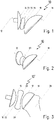
- Fig. 2 shows shoulder prosthesis 10 in an perspective view to display the lens-like design of glenohumeral bearing component 20.
- the glenohumeral bearing component 20 has the shape of a concave-concave lens.
- convex-concave or concave-convex designs are also conceivable.
- implant a 2 is provided with a convex bone interface surface i 1 cooperating with a concave resected bone surface i 2 .
- Load L generates compressional reaction forces on the upper end of implant a 1 .
- parasitic tensile forces are generated, again indicated exemplarily by a circle.
- Fig. 9 shows a portion of a patient's scapula 36 prepared to receive glenoidal component 12".
- a suitably resected bone surface 35 is convex. The preparation involves only a minor bone resection conserving enough natural bone material for later revisions of the shoulder prosthesis, if needed.
Landscapes
- Health & Medical Sciences (AREA)
- Orthopedic Medicine & Surgery (AREA)
- Cardiology (AREA)
- Oral & Maxillofacial Surgery (AREA)
- Transplantation (AREA)
- Engineering & Computer Science (AREA)
- Biomedical Technology (AREA)
- Heart & Thoracic Surgery (AREA)
- Vascular Medicine (AREA)
- Life Sciences & Earth Sciences (AREA)
- Animal Behavior & Ethology (AREA)
- General Health & Medical Sciences (AREA)
- Public Health (AREA)
- Veterinary Medicine (AREA)
- Prostheses (AREA)
Description
- The present disclosures relates to a shoulder prosthesis to be used in shoulder arthroplasty.
- Shoulder pathology often involves disruption of the glenohumeral joint and/ or an impairment of its functional components. A suitable treatment can involve a prosthetic replacement of the affected components of the natural joint. A partial reconstruction of the glenohumeral joint comprises the replacement of the natural articulation surface of the glenoidal component or the humeral component of the shoulder. In a complete reconstruction of the glenohumeral joint - also referred to as total shoulder arthroplasty (TSA) - both of the natural components mentioned above are replaced by prosthetic implants.
- Documents
EP 0 850 609 A1 ,US 2009/01 12328 A1 ,US 7,799,077 B2 andUS 5,593,445 A disclose exemplary shoulder joint prostheses with kinematics mimicking in principle the kinematics of a natural shoulder joint, i.e. the humeral component of the prostheses is provided with a convex articulation surface. DocumentEP 1 649 836 A2 discloses a prosthesis with an inverse kinematics. A further exemplary shoulder joint prosthesis is disclosed byWO 94/ 10941 A1 - Here, a novel concept of a shoulder prosthesis is suggested that has improved kinematics and that can be reliably fixed to the bone components involved.
-
EP 1 649 836 A2 discloses a prosthesis according to the preamble of claim 1. The invention is defined in claim 1, which provides a shoulder prosthesis comprising a glenoidal component having a glenoidal articulation surface and a humeral component having a humeral articulation surface. Further, a separate mobile glenohumeral bearing component comprising a glenoidal bearing surface and a humeral bearing surface arranged on opposite sides of the glenohumeral bearing component is provided. The glenoidal bearing surface contacts in an implanted state the glenoidal articulation surface. Additionally, the humeral bearing surface contacts in an implanted state the humeral articulation surface. At least one of the glenoidal and humeral bearing surfaces is concave. - Such a design has the advantages of a mobile bearing that acts as inter- positional spacer while being very compact and having advantageous kinematic properties. The concave shape of at least one of the bearing surfaces brings the articulation close to the center of the prosthesis leading to an articulation kinematics that resembles closely the natural articulation. Further, a reduction of the stress and strain exerted on the components of the prostheses and adjacent portions the humerus and/or the scapula can be achieved.
- "Mobile" in the context of the present disclosure should be understood as not being mounted to any bone or any other prosthetic component. Hence, the glenohumeral bearing component is merely in articulation contact with the glenoidal component and/or humeral component and is not provided with bone attachment means that secure the glenohumeral bearing component to one or both of said components. The glenohumeral bearing component is thus allowed to move - constrained only by the shape of the interacting surfaces - in reaction to a relative displacement and /or relative rotation of these components. The glenohumeral bearing component can therefore assume automatically an optimal position that reduces contact stresses acting between the functional elements involved.
- The glenoidal articulation surface and the humeral articulation surface are convex. Hence, the glenoidal articulation surface of the glenoidal component is inverted compared to the natural osseous anatomy shifting the focus of the articulation towards the humeral head.
- In yet another embodiment of the shoulder prosthesis, the glenoidal and humeral bearing surfaces have different curvatures and/or sizes to obtain the desired articulation kinematics of the prosthesis. In particular, the glenoidal bearing surface is smaller than the glenoidal articulation surface and/or the humeral bearing surface is smaller than the humeral articulation surface. However, in one embodiment the curvatures and/or the sizes of said surfaces are similar or identical. It is thus possible to choose said parameters as needed to realize the desired articulation kinematics.
- According to another embodiment of the shoulder prosthesis according to the present disclosure, the glenohumeral bearing component comprises a central recess in the glenoidal bearing surface and/or the humeral bearing surface. Alternatively, a central opening extending from the glenoidal bearing surface to the humeral bearing surface may be provided. In other words, the glenohumeral bearing component may be provided with a recess and/or a hole in or close to the center of the bearing component in order to reduce the weight of the bearing component without comprising its functionality.
- The shoulder prosthesis comprises both the glenoidal component and the humeral component, wherein the glenohumeral bearing component is disposed in an implanted state between the glenoidal component and the humeral component. Thus, the glenoidal component and the humeral component are not in direct contact and the glenohumeral bearing component acts as interpositional-spacer between the prosthetic articulation surfaces of said components. Both the glenoidal and humeral articulation surfaces are convex to concentrate the kinematic center of the prosthesis on the glenohumeral bearing component. In such an embodiment, both the bearing surfaces of the glenohumeral bearing component are concave, so that the spatial separation of the articulation surfaces - natural or prosthetic - is rather small in an implanted state of the prosthesis. This concept is in particular suited in cases where a total shoulder arthroplasty is indicated.
- In another embodiment of the shoulder prosthesis, the glenoidal component comprises a glenoidal bone interface provided to be attached to the scapula of a patient and/or the humeral component comprises a humeral bone interface provided to be attached to a humerus of the patient, wherein the glenoidal bone interface or the humeral bone interface of the respective implant component is concave. In particular, both the glenoidal and humeral bone interfaces of the respective implant component are concave. Providing the glenoidal bone interface and/or the humeral bone interface with a concave design reduces tensile stress acting between the bone interface and the bone, especially when eccentric loads are applied. A concave geometry realigns the loads towards the center thereby reducing the occurrence of tensile stress that are particularly detrimental to the fixation reliability at the margin of the respective prosthetic component. In other words, the load distribution acting on the subchondral bone underlying the prosthetic component is improved by providing said component with a concave bone interface. Further, the surgical impact associated with implanting a shoulder prosthesis with a concave glenoidal bone interface and/or a concave humeral bone interface is reduced since less bone material has to be resected. Moreover, as bone material is preserved the convex bone surface adapted to receive such a concave bone interface can - if necessary - be converted by resection relatively easily into a planar or concave surface in case the respective prosthetic component has to be replaced. It should be noted that the advantageous effects associated with a concave bone interface can in principle also be realised in shoulder prosthesis which are not provided with a mobile bearing component and/or which are provided with a bearing component without at least one concave bearing surface.
- The glenoidal bone interface may be disposed on a glenoidal base element that couples with an articulation element of the glenoidal component carrying the glenoidal articulation surface via a first coupling means and/or the humeral bone interface may be disposed on a humeral base element that couples with an articulation element of the prosthetic humeral component carrying the humeral articulation surface via a second coupling means. Said first and/or second coupling means may comprise at least one screw, a taper and/or snap means. In other words, the glenoidal component and/or the humeral component may comprise at least two separate elements provided with different functionalities. For example, first the corresponding base element is fixed to the bone and the articulation element is attached to the base element after it has been made sure that the base element is reliably fixed to the bone. Such an approach may facilitate the implantation of the shoulder prosthesis.
- According to an embodiment of the shoulder prosthesis, the glenohumeral bearing component is made of ceramic and/or polyethylene. The glenoidal component - if applicable the glenoidal articulation element and/or the glenoidal base element - and/or the humeral component - if applicable the humeral articulation element and/or the humeral base element - may be made of metal, metal alloy, ceramic and/or polyethylene.
- To be able to mimic the natural articulation of a shoulder joint and/or to provide the patient with a shoulder prosthesis adapted to his specific needs, the respective curvatures of the articulation surfaces and of the bearing surfaces have to be adjusted accordingly. However, it is not imperative that the articulation surfaces have identical curvatures or that the bearing surfaces have identical curvatures. It is also not imperative to provide the bearing surfaces with the same curvature as the corresponding articulation surfaces. In particular, the curvature of the glenoidal articulation surface and the curvature of the humeral articulation surface may be different from each other and different from that of the corresponding bearing surface. Specifically, the curvature of a concave surface may be smaller than that of the corresponding convex surface with which it is in contact.
- Apart from the curvature of the cooperating surfaces, the thickness and the diameter of the glenohumeral component play an important role in determining the kinematics of the shoulder prosthesis. Hence, these parameters may also be chosen freely to achieve the desired kinematics.
- Another important aspect influencing the kinematics of the shoulder prosthesis is the friction between the components of the shoulder prosthesis during articulation. In an embodiment of the shoulder prosthesis according to the present disclosure, the glenoidal articulation surface, the humeral articulation surface, the glenoidal bearing surface and the humeral bearing surface are designed such and/or the materials of said components are chosen such that a first coefficient of friction between the glenoidal articulation surface and the glenodial bearing surface and a second coefficient or friction between the humeral articulation surface and humeral bearing surface are essentially equivalent. However, different coefficients of friction may be envisaged to create specific kinematic situations in order to meet the individual needs of a given patient. Different coefficients of friction may focus the kinematics and/or the associated loads on the humeral side or the glenoidal side of the shoulder prosthesis.
- Further, a prosthetic glenoidal component of a shoulder prosthesis is suggested that reduces tensile loads acting between said component and the bone to which it is fixed.
- Said prosthetic glenoidal component comprises a glenoidal articulation surface adapted to cooperate directly or indirectly via a glenohumeral bearing component with a natural or with a prosthetic humeral articulation surface. Said prosthetic glenoidal component further comprises a glenoidal bone interface provided to be attached to the scapula of a patient, wherein the glenoidal bone interface is concave. The advantages associated with a concave bone interface have been described in detail above in connection with a shoulder prosthesis according to the present disclosure. These considerations apply analogously to the prosthetic glenoidal component according to the present disclosure.
- According to an embodiment of the prosthetic glenoidal component, the glenoidal articulation surface is convex.
- Further, a glenohumeral bearing component is suggested that is adapted to be used in a shoulder prosthesis according to any of the embodiments described above. In an embodiment of the glenohumeral bearing component, the glenohumeral bearing component comprises a glenoidal bearing surface and a humeral bearing surface arranged on opposite sides of the glenohumeral bearing component. One of the glenoidal bearing and the humeral bearing surfaces is concave and the other of the glenoidal bearing and the humeral bearing surfaces is one of planar, convex or concave.
- A method for implanting a shoulder prosthesis is suggested (not claimed), comprising the steps of providing a prosthetic glenoidal component comprising a glenoidal articulation surface and/or providing a prosthetic humeral component comprising a humeral articulation surface, resecting a glenoidal por- tion of a patient's scapula and attaching the glenoidal component to the resected glenoidal portion and/or resecting a proximal end of a patient's humerus and attaching the humeral component to the resected proximal end portion, and inserting a glenohumeral bearing component comprising a glenoidal bearing surface and a humeral bearing surface, wherein the glenoidal bearing surface contacts in an implanted state the glenoidal articulation surface and/ or wherein the humeral bearing surface contacts in an implanted state the humeral articulation surface. At least one of the glenoidal and humeral bearing surfaces is concave.
- According to a version of the method, the step of resecting the glenoidal portion of a patient's scapula comprises the step of preparing a convex bone portion adapted to match a correspondingly shaped - in particular concave - bone interface of the glenoidal component.
- In another version of the method, the step of providing a glenoidal component comprises providing a glenoidal component comprising a convex glenoidal articulation surface.
- In yet another version of the method, the step of attaching the glenoidal component to the resected glenoidal portion comprises placing the glenoidal component on the convex bone portion and fixing it to the scapula using at least one of a screw, bone cement and a press fit means. A further method of implanting a shoulder prosthesis comprises the steps of providing a prosthetic glenoidal component comprising a glenoidal articulation surface and a glenoidal bone interface provided to be attached to a scapula of a patient, resecting a glenoidal portion of a patient's scapula to form a convex bone portion adapted to match the correspondingly shaped - in particular concave - glenoidal bone interface and fixing the glenoidal component to the resected glenoidal portion.
- The different variations of the shoulder prosthesis, the prosthetic glenoidal component, the glenohumeral bearing component and the methods of implanting a shoulder prosthesis described above in accordance with the scope of the independent claims and the features realized there can naturally be combined with one another.
- Further embodiments of the disclosure are also recited in the dependent claims, the description and the drawings.
- Further areas of applicability of the present disclosure will become apparent from the detailed description provided hereinafter. It should be understood that the detailed description and the specific examples are intended for purpose of illustration only and are not intended to limit the scope of the invention in any way. The figures are simplified in schematic. Details not necessary for the understanding of the invention are omitted.
- The present disclosure will be explained in more detail and become fully understood from the detailed description and the accompanying drawings, wherein
- Figs. 1 and 2
- depict an embodiment of the shoulder prosthesis in accordance with the present disclosure in different perspective views,
- Fig. 3
- shows schematically a similar embodiment of the shoulder prosthesis in accordance with the present disclosure,
- Figs. 4 and 5
- show schematically an example of the prosthetic glenoidal component in accordance with the present disclosure,
- Fig. 6
- shows an example of the prosthetic glenoidal component comprising a base element and an articulation element,
- Figs. 7a to 7c
- show load distributions resulting from different bone interface geometries,
- Fig. 8a and 8b
- show yet another example of the prosthetic glenoidal component in accordance with the present disclosure in different views,
- Fig. 9
- shows a scapula resected to receive the glenoidal component of
Figs. 9a and 9b , - Fig. 10
- shows the glenoidal component of
Figs. 9a and 9b attached to the resected scapula, - Figs. 11a and 11b
- show a further example of the prosthetic glenoidal component in accordance with the present disclosure,
- Figs. 12 to 14
- show different examples of a glenohumeral bearing component in accordance with the present disclosure,
- Fig. 15
- shows an example of a prosthetic glenoidal component in accordance with the present disclosure and
- Fig. 16
- shows yet another example of a glenohumeral bearing component in accordance with the present disclosure.
-
Fig. 1 shows ashoulder prosthesis 10 comprising aglenoidal component 12 attached in an implanted state to a scapula of a patient and ahumeral component 14 attached in an implanted state to a humeral head of the humerus of a patient.Glenoidal component 12 comprises - contrary to the natural anatomy - a convexglenoidal articulation surface 16.Humeral component 14 is provided with ahumeral articulation surface 18. - In an implanted state, surfaces 16, 18 are not in direct contact with each other but are separated by
glenohumeral bearing component 20.Glenohumeral bearing component 20 therefore acts as a spacer disposed betweencomponents Glenohumeral bearing component 20 comprises a glenoidal bearing surface 22 that is in an implanted state ofprosthesis 10 in contact withglenoidal articulation surface 16. On the opposite side,glenohumeral bearing component 20 is provided with humeral bearingsurface 24 that is in an implanted state ofprosthesis 10 in contact withhumeral articulation surface 18. -
Glenohumeral bearing component 20 is not attached to neither ofcomponents surfaces glenohumeral bearing component 20 relative tocomponents surfaces glenohumeral bearing component 20 is a separate, mobile component andshoulder prosthesis 10 can be described as a mobile bearing shoulder system particularly suitable for total shoulder arthroplasty intended for patients who have intact and functional rotor cuff musculature. However, it should be understood, that the principle of the shoulder prosthesis according to the present disclosure can also be applied to prostheses used in partial shoulder arthroplasty in which e.g. the natural humeral head is preserved. -
Fig. 2 showsshoulder prosthesis 10 in an perspective view to display the lens-like design ofglenohumeral bearing component 20. In this example, theglenohumeral bearing component 20 has the shape of a concave-concave lens. However, it should be appreciated that convex-concave or concave-convex designs are also conceivable. -
Fig. 3 shows schematically a shoulder prosthesis 10' which is functionally similar toshoulder prosthesis 10.Humeral component 14 of shoulder prosthesis 10' is fixed to the proximal end ofhumerus 26 replacing - at least partially - its head. The natural articulation surface ofhumerus 26 has therefore been substituted byprosthetic articulation surface 18 ofhumeral component 14. - It can be seen from
Fig. 3 that both bearingsurfaces glenohumeral bearing component 20 are concave and that no attachment means are provided to secure or fixcomponent 20 to one of or bothcomponents glenohumeral bearing component 20 relative tocomponents surfaces surfaces surfaces surfaces glenohumeral bearing component 20. In contrast, ifsurfaces glenoidal component 12 relative toglenohumeral component 20 on one the hand and the motion ofhumeral component 14 relative toglenohumeral bearing component 20 one the other hand would be spatially separated substantially leading to an unnatural overall articulation kinematics. Hence, shoulder prosthesis 10' combines the advantages of a mobile bearing system with a compact design without compromising a natural articulation. - In other words, the mobile bearing concept of the present disclosure comprises a
glenohumeral bearing component 20 that is compact - in most cases smaller thancomponents 12, 14 - and that is free to articulate and to move betweencomponents surfaces glenohumeral bearing component 20 in the optimal position which leads to a reduction of contact stresses. - Moreover, the concave design of
surfaces components -
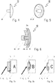
Fig. 4 showsglenoidal component 12 of prosthesis 10' in a sideview.Glenoidal component 12 can be attached to the scapula of a patient via taperedpeg 28. In principle, all known concepts of attaching a prosthesis to a bone can be contemplated when choosing a suitable approach to fixcomponent 12 to the scapula. The same applies to means and methods for fixinghumeral component 14 tohumerus 26. -
Fig. 5 shows schematicallyglenoidal component 12 from the bone interface side to visualize the geometry of abone interface surface 29 ofglenoidal component 12. It is not flat but has a concave shape from which peg 28 extends. - As depicted in
Fig. 6 , instead of a direct fixation ofglenoidal component 12 to the scapula, it may be envisaged to provide a glenoidal component 12' with abase element 30 comprising a concave bone interface surface 29'.Base element 30 receives anarticulation element 32 comprisingglenoidal articulation surface 16. Glenoidal component 12' therefore comprises twoseparate elements Base element 30 andarticulation element 32 of glenoidal component 12' comprise convex and concave contactingsurfaces - Exemplarily,
first base element 30 is attached to the bone during implantation of component 12'. Then,articulation element 32 is attached tobase element 30 in a following step. Thus,base element 30 serves as an anchor that allows to fixarticulation element 32 to the bone. It should be understood thathumeral component 14 may be designed analogously. -
Figs. 7a to 7c show the effect of the geometry of the bone interface surface on the stress and strain regime during articulation in a generalized form. - In all shown cases the load acting on a prosthetic component or implant a1, a2, a3 attached to a bone b is depicted by arrow L. The resultant stress produced in bone b is indicated by small arrows 1.
- In
Fig. 8a , both a bone interface surface i1 of implant a1 and resected bone surface i2 of bone b receiving bone interface surface i1 are essentially flat. - This geometry leads to tensile forces especially in the areas denoted by a circle.
- In
Fig. 8b , implant a2 is provided with a convex bone interface surface i1 cooperating with a concave resected bone surface i2. Load L generates compressional reaction forces on the upper end of implant a1. In the lower part parasitic tensile forces are generated, again indicated exemplarily by a circle. - In
Fig. 8c implant a3 has a concave bone interface surface i1 cooperating with a convex resected bone surface i2. Load L is realigned by this geometry towards a central region of implant a3 thereby greatly reducing the occurrence of tensile forces that are especially detrimental for the fixation of an implant to a bone. -
Fig. 8a and 8b show afurther embodiment 12" of a glenoidal component with a concavebone interface surface 29. It can be seen thatglenoidal component 12" is more massive thanglenoidal components 12, 12' and that the curvature of itsarticulation surface 16 is larger. -
Fig. 9 shows a portion of a patient'sscapula 36 prepared to receiveglenoidal component 12". A suitably resectedbone surface 35 is convex. The preparation involves only a minor bone resection conserving enough natural bone material for later revisions of the shoulder prosthesis, if needed. -
Fig. 10 showsglenoidal component 12" fixed toscapula 36. It should be understood that the fixation ofglenoidal component 12" may involve more than one fixation pegs or other suitable fixation means instead of or in addition topeg 28. Bone cement can be used to assist the fixation ofglenoidal component 12" toscapula 36. -
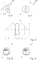
Fig. 11a shows a further embodiment 12'" of a glenoidal component provided with a relatively massive fixation peg 28 - optimized for a press fit - extending frombone interface surface 29. It can be seen that a curvature radius r1 ofbone interface surface 29 is smaller than a curvature radius r2 ofglenoidal articulation surface 16. The center of radius r2 is shifted towards component 12'" to compensate the fact thatsurfaces -
Fig. 11b depicts a backview of glenoidal component 12'" revealing that it is provided - in addition to centrally arranged peg 28 - with screw holes 38 that can be used to improve the fixation of glenoidal component 12'" to the bone, if needed. Of course, only onescrew hole 38 or more that twoscrew holes 38 can be provided. -
Fig. 12 shows an lens-like embodiment 20' of a glenohumeral bearing component according to the present disclosure. Both theglenoidal bearing surface 22 and thehumeral bearing surface 24 are defined by a specific curvature suitably chosen in consideration of the curvature of thecorresponding articulation surface glenoidal bearing surface 22 has a curvature radius r3 andhumeral bearing surface 24 has a curvature radius r4. Curvature radii r3, r4 can be chosen as needed, e.g. r3 = r4, r3 > r4, r3 < r4. Further parameters that might be chosen freely in order to obtain the desired kinematics are - inter alia - a diameter d of glenohumeral bearing component 20' or its minimum thickness t1 and/or its maximum thickness t2. -
Figs. 13 and 14 show further embodiments 20", 20"', respectively, of a glenohumeral bearing component according to the present disclosure.Glenohumeral bearing component 20" shown inFig. 13 is provided with arecess 40 in the center ofsurfaces recess 40. - As it can be seen in
Fig. 14 , instead ofrecesses 40, ahole 42 can be provided in a central region of glenohumeral bearing component 20'" in order to save even more material and to reduce its weight. Figuratively speaking, glenohumeral bearing component 20'" is toroidally shaped, i.e. resembles a doughnut. The removal of material in a central region ofglenohumeral bearing components 20", 20'" does not compromise the kinematics of the shoulder prosthesis when combined with suitable glenoidal and humeral components. -
Fig. 15 discloses afurther embodiment 12"" of a glenoidal component according to the present disclosure.Glenoidal component 12"" has a concavebone interface surface 29 with a curvature radius r5 and a concave glenoidal articulation surface 16' with a curvature radius r6. Radii r5, r6 may be equal or different. - Exemplarily, a
glenoidal component 12"" as depicted inFig. 15 may be used in combination with ahumeral component 14 as shown e.g. inFigs. 1 to 3 . A suitableglenohumeral bearing component 20"" is shown inFig. 16 . It has a convex glenoidal bearing surface 22' and a concave humeral bearing surface 24'. Hence,glenohumeral bearing component 20"" has a more bean-like appearance compared to the lens-like shape ofglenohumeral bearing components - It should be understood that
glenohumeral bearing component 20"" can also be used in shoulder prostheses with a convex glenoidal articulation surface and a concave humeral articulation surface. -
- 10, 10'
- shoulder prosthesis
- 12, 12', 12", 12"', 12""
- glenoidal component
- 14
- humeral component
- 16, 16'
- glenoidal articulation surface
- 18
- humeral articulation surface
- 20, 20', 20", 20"', 20""
- glenohumeral bearing component
- 22, 22'
- glenoidal bearing surface
- 24, 24'
- humeral bearing surface
- 26
- humerus
- 28
- peg
- 29, 29'
- bone interface surface
- 30
- base element
- 32
- articulation element
- 34a, 34b
- contacting surface
- 35
- resected bone surface
- 36
- scapula
- 38
- screw hole
- 40
- recess
- 42
- hole
- r1, r2, r3, r4, r5, r6
- curvature radius
- a1, a2, a3
- implant
- L, 1
- load
- b
- bone
- i1
- bone interface surface
- i2
- resected bone surface
- t1, t2
- thickness
- d
- diameter
Claims (8)
- Shoulder prosthesis comprising:- a glenoidal component (12, 12', 12", 12"', 12"") having a glenoidal articulation surface (16, 16') and a humeral component (14) having a humeral articulation surface (18), and- a separate mobile glenohumeral bearing component (20, 20', 20", 20'', 20"") comprising a glenoidal bearing surface (22, 22') and a humeral bearing surface (24, 24') arranged on opposite sides of the glenohumeral bearing component (20, 20', 20", 20"', 20""), wherein the glenoidal bearing surface (22, 22') is adapted to contact in an implanted state the glenoidal articulation surface (16, 16') and wherein the humeral bearing surface (24, 24') is adapted to contact in an implanted state the humeral articulation surface (18),wherein at least one of the glenoidal and humeral bearing surfaces (22, 22', 24, 24') is concave,
wherein the glenohumeral bearing component (20, 20', 20", 20'" 20"") is adapted to be disposed in an implanted state between the glenoidal component (12, 12', 12", 12"', 12"") and the humeral component (14), and
wherein the glenoidal articulation surface (16) is convex, characterized in that
the humeral articulation surface (18) is also convex. - Shoulder prosthesis according to claim 1, wherein the glenohumeral bearing component (20, 20', 20", 20"', 20"") is in an implanted state of the shoulder prosthesis adapted to be mobile relative to the glenoidal component (12, 12', 12", 12"', 12"") and/or the humeral component (14).
- Shoulder prosthesis according to any of the preceding claims, wherein the glenoidal and humeral bearing surfaces (22, 22', 24, 24') have different curvatures and/or sizes.
- Shoulder prosthesis according to any of the preceding claims, wherein the glenohumeral bearing component (20", 20"') comprises a central recess (40) in the glenoidal bearing surface (22, 22') and/or a central opening (42) extending from the glenoidal bearing surface (22, 22') to the humeral bearing surface (24, 24').
- Shoulder prosthesis according to any of the preceding claims, wherein the glenoidal component (12, 12', 12", 12"', 12"") comprises a glenoidal bone interface (29, 29') provided to be attached to a scapula (36) of a patient and/or wherein the humeral component (14) comprises a humeral bone interface provided to be attached to a humerus (26) of a patient, wherein the glenoidal interface (29, 29') or the humeral bone interface is concave.
- Shoulder prosthesis according to claim 5, wherein the glenoidal bone interface (29, 29') is disposed on a glenoidal base element (30) that is adapted to couple with an articulation element (32) of the glenoidal component (12') carrying the glenoidal articulation surface (16) via a first coupling means and/or wherein the humeral bone interface is disposed on a humeral base element that is adapted to couple with an articulation element of the prosthetic humeral component carrying the humeral articulation surface via a second coupling means.
- Shoulder prosthesis according to any of the preceding claims, wherein the glenohumeral bearing component (20, 20', 20", 20"', 20"") is made of ceramic and/or polyethylene.
- Shoulder prosthesis according to any of the preceding claims, wherein the glenoidal articulation surface (16, 16'), the humeral articulation surface (18), the glenoidal bearing surface (22, 22') and the humeral bearing surface (24, 24') are designed such and/or the materials of said components are chosen such that a first coefficient of friction between the glenoidal articulation surface (16, 16') and the glenoidal bearing surface (22, 22') and a second coefficient of friction between the humeral articulation surface (18) and the humeral bearing surface (24, 24') are essentially equivalent.
Priority Applications (1)
| Application Number | Priority Date | Filing Date | Title |
|---|---|---|---|
| EP13810962.4A EP2895113B1 (en) | 2012-12-27 | 2013-12-19 | Shoulder prosthesis |
Applications Claiming Priority (3)
| Application Number | Priority Date | Filing Date | Title |
|---|---|---|---|
| EP12199430.5A EP2749255A1 (en) | 2012-12-27 | 2012-12-27 | Shoulder prosthesis and components thereof |
| PCT/EP2013/077419 WO2014102141A1 (en) | 2012-12-27 | 2013-12-19 | Shoulder prosthesis and components thereof |
| EP13810962.4A EP2895113B1 (en) | 2012-12-27 | 2013-12-19 | Shoulder prosthesis |
Publications (2)
| Publication Number | Publication Date |
|---|---|
| EP2895113A1 EP2895113A1 (en) | 2015-07-22 |
| EP2895113B1 true EP2895113B1 (en) | 2017-08-16 |
Family
ID=47681540
Family Applications (2)
| Application Number | Title | Priority Date | Filing Date |
|---|---|---|---|
| EP12199430.5A Withdrawn EP2749255A1 (en) | 2012-12-27 | 2012-12-27 | Shoulder prosthesis and components thereof |
| EP13810962.4A Active EP2895113B1 (en) | 2012-12-27 | 2013-12-19 | Shoulder prosthesis |
Family Applications Before (1)
| Application Number | Title | Priority Date | Filing Date |
|---|---|---|---|
| EP12199430.5A Withdrawn EP2749255A1 (en) | 2012-12-27 | 2012-12-27 | Shoulder prosthesis and components thereof |
Country Status (7)
| Country | Link |
|---|---|
| US (2) | US9763797B2 (en) |
| EP (2) | EP2749255A1 (en) |
| CN (1) | CN104884003B (en) |
| AU (1) | AU2013369450B2 (en) |
| CA (1) | CA2893463C (en) |
| ES (1) | ES2647629T3 (en) |
| WO (1) | WO2014102141A1 (en) |
Families Citing this family (8)
| Publication number | Priority date | Publication date | Assignee | Title |
|---|---|---|---|---|
| EP2749255A1 (en) | 2012-12-27 | 2014-07-02 | Zimmer GmbH | Shoulder prosthesis and components thereof |
| US9681960B2 (en) | 2014-05-16 | 2017-06-20 | Howmedica Osteonics Corp. | Guides for fracture system |
| US10575968B2 (en) | 2014-05-16 | 2020-03-03 | Howmedica Osteonics Corp. | Guides for fracture system |
| US9844440B2 (en) | 2014-08-14 | 2017-12-19 | Biomet Manufacturing, Llc | Glenoid implant |
| EP3361994B1 (en) | 2015-10-15 | 2019-12-18 | Zimmer, Inc. | Stemless shoulder implant |
| EP3332749B1 (en) | 2016-12-06 | 2020-09-02 | Tornier | Shoulder prosthesis comprising a glenohumeral component |
| US11571310B2 (en) | 2019-04-03 | 2023-02-07 | Catalyst Orthoscience Inc. | Stemmed implant |
| CN110353860A (en) * | 2019-07-31 | 2019-10-22 | 周广东 | A kind of organizational project humerus head surface replacement prosthesis and its fabrication and installation method |
Family Cites Families (32)
| Publication number | Priority date | Publication date | Assignee | Title |
|---|---|---|---|---|
| US4003095A (en) * | 1976-04-29 | 1977-01-18 | Howmedica, Inc. | Trispherical prosthetic shoulder device |
| DE3908958C2 (en) * | 1989-03-18 | 1996-09-12 | Kubein Meesenburg Dietmar | Artificial joint |
| DE4238832C1 (en) | 1992-11-17 | 1994-08-11 | Plus Endoprothetik Ag | Shoulder joint endoprosthesis |
| JP3164675B2 (en) | 1992-12-28 | 2001-05-08 | 京セラ株式会社 | Joint component |
| US5593445A (en) * | 1995-03-24 | 1997-01-14 | Waits; C. Thomas | Bi-axial prosthetic joint |
| FR2757764B1 (en) * | 1996-12-30 | 1999-01-29 | Aesculap Sa | HUMER PROSTHESIS WITH MOBILE HEAD |
| US7799077B2 (en) * | 2002-10-07 | 2010-09-21 | Conformis, Inc. | Minimally invasive joint implant with 3-dimensional geometry matching the articular surfaces |
| CN2322572Y (en) * | 1998-03-25 | 1999-06-09 | 周袭明 | Tuna shape hip joint prosthesis |
| US20070162140A1 (en) * | 2001-02-27 | 2007-07-12 | Mcdevitt Dennis M | Method and apparatus for reconstructing a joint |
| US8753402B2 (en) * | 2001-07-27 | 2014-06-17 | Biomet Manufacturing, Llc | Modular humeral head resurfacing system |
| FR2841768B1 (en) * | 2002-07-05 | 2005-05-06 | Tornier Sa | SHOULDER OR HIP PROSTHESIS FACILITATING ABDUCTION |
| DE50205821D1 (en) | 2002-08-30 | 2006-04-20 | Zimmer Gmbh Winterthur | operation system |
| ITUD20030094A1 (en) | 2003-04-30 | 2004-11-01 | Lima Lto Spa | REVERSE PROSTHESIS FOR THE JOINT OF THE SHOULDER. |
| US8070820B2 (en) * | 2003-10-08 | 2011-12-06 | Biomet Manufacturing Corp. | Shoulder implant assembly |
| EP1598034B1 (en) | 2004-05-19 | 2011-03-30 | Zimmer GmbH | Glenoidal anchorage |
| US7241314B1 (en) | 2004-09-16 | 2007-07-10 | Biomet Manufacturing Corp. | Reverse shoulder prosthesis |
| ITUD20040195A1 (en) * | 2004-10-20 | 2005-01-20 | Lima Lto Spa | REVERSE PROSTHESIS FOR THE ARTICULATION OF THE SHOULDER |
| EP1787603A1 (en) | 2005-11-18 | 2007-05-23 | Zimmer GmbH | Basis-platform for an artificial joint |
| JP4963838B2 (en) | 2006-02-06 | 2012-06-27 | 京セラメディカル株式会社 | Low wear sliding member and artificial joint using the same |
| US8425614B2 (en) | 2006-03-20 | 2013-04-23 | Biomet Manufacturing Corp. | Modular center pegged glenoid |
| WO2007109291A2 (en) | 2006-03-21 | 2007-09-27 | Axiom Orthopaedics, Inc. | Non-spherical articulating surfaces in shoulder and hip prosthesis |
| FR2900045B1 (en) * | 2006-04-21 | 2009-01-16 | Tornier Sas | PROSTHESIS OF SHOULDER OR HIP |
| US20090287309A1 (en) | 2007-01-30 | 2009-11-19 | Tornier Sas | Intra-articular joint replacement |
| NZ594917A (en) * | 2009-03-11 | 2014-02-28 | Exactech Inc | Motion inducing reverse shoulder assembly |
| US20110106267A1 (en) * | 2009-10-30 | 2011-05-05 | Depuy Products, Inc. | Shoulder prosthesis adjustable humeral head mechanism |
| US8246687B2 (en) | 2009-11-18 | 2012-08-21 | Biomet Manufacturing Corp. | Shoulder prosthetic |
| US9408652B2 (en) | 2010-04-27 | 2016-08-09 | Tornier Sas | Intra-articular joint replacement and method |
| EP2672929A4 (en) * | 2011-02-07 | 2018-01-31 | Exactech Inc. | Adjustable reverse shoulder prostheses |
| WO2012125704A2 (en) | 2011-03-14 | 2012-09-20 | Topsfield Medical Gmbh | Implantable glenoid prostheses |
| US8702800B2 (en) | 2011-08-23 | 2014-04-22 | Linares Medical Devices, Llc | Multi-component shoulder implant assembly with dual articulating surfaces |
| EP2749255A1 (en) | 2012-12-27 | 2014-07-02 | Zimmer GmbH | Shoulder prosthesis and components thereof |
| EP3361994B1 (en) | 2015-10-15 | 2019-12-18 | Zimmer, Inc. | Stemless shoulder implant |
-
2012
- 2012-12-27 EP EP12199430.5A patent/EP2749255A1/en not_active Withdrawn
-
2013
- 2013-12-19 WO PCT/EP2013/077419 patent/WO2014102141A1/en not_active Ceased
- 2013-12-19 EP EP13810962.4A patent/EP2895113B1/en active Active
- 2013-12-19 US US14/439,605 patent/US9763797B2/en active Active
- 2013-12-19 ES ES13810962.4T patent/ES2647629T3/en active Active
- 2013-12-19 CA CA2893463A patent/CA2893463C/en active Active
- 2013-12-19 CN CN201380068443.8A patent/CN104884003B/en active Active
- 2013-12-19 AU AU2013369450A patent/AU2013369450B2/en active Active
-
2017
- 2017-08-23 US US15/684,578 patent/US10687949B2/en active Active
Non-Patent Citations (1)
| Title |
|---|
| None * |
Also Published As
| Publication number | Publication date |
|---|---|
| EP2895113A1 (en) | 2015-07-22 |
| AU2013369450B2 (en) | 2017-06-01 |
| US10687949B2 (en) | 2020-06-23 |
| ES2647629T3 (en) | 2017-12-22 |
| US20170348111A1 (en) | 2017-12-07 |
| AU2013369450A1 (en) | 2015-05-21 |
| CA2893463A1 (en) | 2014-07-03 |
| EP2749255A1 (en) | 2014-07-02 |
| WO2014102141A1 (en) | 2014-07-03 |
| US9763797B2 (en) | 2017-09-19 |
| CN104884003B (en) | 2016-09-07 |
| CN104884003A (en) | 2015-09-02 |
| CA2893463C (en) | 2021-08-31 |
| US20150289985A1 (en) | 2015-10-15 |
Similar Documents
| Publication | Publication Date | Title |
|---|---|---|
| US10687949B2 (en) | Shoulder prosthesis and components thereof | |
| EP2566417B1 (en) | Mobile bearing glenoid prosthesis | |
| US9283083B2 (en) | Shoulder implant assembly | |
| AU2009217048B2 (en) | Shoulder joint prosthesis, especially reverse shoulder joint prosthesis | |
| EP3311780B1 (en) | Spring base glenosphere | |
| JP3549532B2 (en) | Shoulder prosthesis | |
| EP2665445B1 (en) | Reverse shoulder prosthetic | |
| EP1983945B1 (en) | Modular intervertebral disc replacements | |
| EP2854712B1 (en) | Reverse shoulder humeral adapter trays | |
| EP2306935B1 (en) | A base component for a tibial implant | |
| CN103260553B (en) | Prosthetic patella | |
| EP3490466B1 (en) | Platform rtsa glenoid prosthesis with modular attachments capable of improving initial fixation, fracture reconstructions, and joint biomechanics | |
| EP2523635B1 (en) | Acromion spacer | |
| US20060074492A1 (en) | Endoprosthesis for a metatarsophalangeal joint | |
| US8277511B2 (en) | Shoulder or hip prosthesis and method for setting same | |
| EP2775963B1 (en) | Prosthesis component | |
| CN102470036A (en) | Prosthetic spinal disc system | |
| US20070191952A1 (en) | Spinal implant with elliptical articulatory interface | |
| CN101980672A (en) | Intervertebral disk prosthesis notably for cervical vertebrae | |
| WO2010052461A1 (en) | Medical device | |
| Flatow | Prosthetic design considerations in total shoulder arthroplasty | |
| EP3332749B1 (en) | Shoulder prosthesis comprising a glenohumeral component | |
| EP4093336B1 (en) | Mobile bearing reversed humeral implant | |
| EP4640187A1 (en) | Reverse shoulder arthroplasty with dual mobility | |
| US20250325376A1 (en) | Reverse shoulder arthroplasty with dual mobility |
Legal Events
| Date | Code | Title | Description |
|---|---|---|---|
| PUAI | Public reference made under article 153(3) epc to a published international application that has entered the european phase |
Free format text: ORIGINAL CODE: 0009012 |
|
| 17P | Request for examination filed |
Effective date: 20150417 |
|
| AK | Designated contracting states |
Kind code of ref document: A1 Designated state(s): AL AT BE BG CH CY CZ DE DK EE ES FI FR GB GR HR HU IE IS IT LI LT LU LV MC MK MT NL NO PL PT RO RS SE SI SK SM TR |
|
| AX | Request for extension of the european patent |
Extension state: BA ME |
|
| RIN1 | Information on inventor provided before grant (corrected) |
Inventor name: HOPKINS, ANDREW Inventor name: HARDY, PHILIPPE |
|
| DAX | Request for extension of the european patent (deleted) | ||
| 17Q | First examination report despatched |
Effective date: 20160829 |
|
| STAA | Information on the status of an ep patent application or granted ep patent |
Free format text: STATUS: EXAMINATION IS IN PROGRESS |
|
| GRAP | Despatch of communication of intention to grant a patent |
Free format text: ORIGINAL CODE: EPIDOSNIGR1 |
|
| STAA | Information on the status of an ep patent application or granted ep patent |
Free format text: STATUS: GRANT OF PATENT IS INTENDED |
|
| INTG | Intention to grant announced |
Effective date: 20170227 |
|
| GRAS | Grant fee paid |
Free format text: ORIGINAL CODE: EPIDOSNIGR3 |
|
| GRAA | (expected) grant |
Free format text: ORIGINAL CODE: 0009210 |
|
| STAA | Information on the status of an ep patent application or granted ep patent |
Free format text: STATUS: THE PATENT HAS BEEN GRANTED |
|
| AK | Designated contracting states |
Kind code of ref document: B1 Designated state(s): AL AT BE BG CH CY CZ DE DK EE ES FI FR GB GR HR HU IE IS IT LI LT LU LV MC MK MT NL NO PL PT RO RS SE SI SK SM TR |
|
| REG | Reference to a national code |
Ref country code: GB Ref legal event code: FG4D |
|
| REG | Reference to a national code |
Ref country code: CH Ref legal event code: EP Ref country code: CH Ref legal event code: NV Representative=s name: DR. GRAF AND PARTNER AG INTELLECTUAL PROPERTY, CH |
|
| REG | Reference to a national code |
Ref country code: IE Ref legal event code: FG4D |
|
| REG | Reference to a national code |
Ref country code: AT Ref legal event code: REF Ref document number: 918346 Country of ref document: AT Kind code of ref document: T Effective date: 20170915 |
|
| REG | Reference to a national code |
Ref country code: DE Ref legal event code: R096 Ref document number: 602013025218 Country of ref document: DE |
|
| REG | Reference to a national code |
Ref country code: FR Ref legal event code: PLFP Year of fee payment: 5 |
|
| REG | Reference to a national code |
Ref country code: NL Ref legal event code: MP Effective date: 20170816 |
|
| REG | Reference to a national code |
Ref country code: ES Ref legal event code: FG2A Ref document number: 2647629 Country of ref document: ES Kind code of ref document: T3 Effective date: 20171222 |
|
| REG | Reference to a national code |
Ref country code: LT Ref legal event code: MG4D |
|
| REG | Reference to a national code |
Ref country code: AT Ref legal event code: MK05 Ref document number: 918346 Country of ref document: AT Kind code of ref document: T Effective date: 20170816 |
|
| PG25 | Lapsed in a contracting state [announced via postgrant information from national office to epo] |
Ref country code: NO Free format text: LAPSE BECAUSE OF FAILURE TO SUBMIT A TRANSLATION OF THE DESCRIPTION OR TO PAY THE FEE WITHIN THE PRESCRIBED TIME-LIMIT Effective date: 20171116 Ref country code: SE Free format text: LAPSE BECAUSE OF FAILURE TO SUBMIT A TRANSLATION OF THE DESCRIPTION OR TO PAY THE FEE WITHIN THE PRESCRIBED TIME-LIMIT Effective date: 20170816 Ref country code: NL Free format text: LAPSE BECAUSE OF FAILURE TO SUBMIT A TRANSLATION OF THE DESCRIPTION OR TO PAY THE FEE WITHIN THE PRESCRIBED TIME-LIMIT Effective date: 20170816 Ref country code: FI Free format text: LAPSE BECAUSE OF FAILURE TO SUBMIT A TRANSLATION OF THE DESCRIPTION OR TO PAY THE FEE WITHIN THE PRESCRIBED TIME-LIMIT Effective date: 20170816 Ref country code: LT Free format text: LAPSE BECAUSE OF FAILURE TO SUBMIT A TRANSLATION OF THE DESCRIPTION OR TO PAY THE FEE WITHIN THE PRESCRIBED TIME-LIMIT Effective date: 20170816 Ref country code: AT Free format text: LAPSE BECAUSE OF FAILURE TO SUBMIT A TRANSLATION OF THE DESCRIPTION OR TO PAY THE FEE WITHIN THE PRESCRIBED TIME-LIMIT Effective date: 20170816 |
|
| PG25 | Lapsed in a contracting state [announced via postgrant information from national office to epo] |
Ref country code: PL Free format text: LAPSE BECAUSE OF FAILURE TO SUBMIT A TRANSLATION OF THE DESCRIPTION OR TO PAY THE FEE WITHIN THE PRESCRIBED TIME-LIMIT Effective date: 20170816 Ref country code: RS Free format text: LAPSE BECAUSE OF FAILURE TO SUBMIT A TRANSLATION OF THE DESCRIPTION OR TO PAY THE FEE WITHIN THE PRESCRIBED TIME-LIMIT Effective date: 20170816 Ref country code: IS Free format text: LAPSE BECAUSE OF FAILURE TO SUBMIT A TRANSLATION OF THE DESCRIPTION OR TO PAY THE FEE WITHIN THE PRESCRIBED TIME-LIMIT Effective date: 20171216 Ref country code: LV Free format text: LAPSE BECAUSE OF FAILURE TO SUBMIT A TRANSLATION OF THE DESCRIPTION OR TO PAY THE FEE WITHIN THE PRESCRIBED TIME-LIMIT Effective date: 20170816 Ref country code: GR Free format text: LAPSE BECAUSE OF FAILURE TO SUBMIT A TRANSLATION OF THE DESCRIPTION OR TO PAY THE FEE WITHIN THE PRESCRIBED TIME-LIMIT Effective date: 20171117 Ref country code: BG Free format text: LAPSE BECAUSE OF FAILURE TO SUBMIT A TRANSLATION OF THE DESCRIPTION OR TO PAY THE FEE WITHIN THE PRESCRIBED TIME-LIMIT Effective date: 20171116 |
|
| PG25 | Lapsed in a contracting state [announced via postgrant information from national office to epo] |
Ref country code: RO Free format text: LAPSE BECAUSE OF FAILURE TO SUBMIT A TRANSLATION OF THE DESCRIPTION OR TO PAY THE FEE WITHIN THE PRESCRIBED TIME-LIMIT Effective date: 20170816 Ref country code: CZ Free format text: LAPSE BECAUSE OF FAILURE TO SUBMIT A TRANSLATION OF THE DESCRIPTION OR TO PAY THE FEE WITHIN THE PRESCRIBED TIME-LIMIT Effective date: 20170816 Ref country code: DK Free format text: LAPSE BECAUSE OF FAILURE TO SUBMIT A TRANSLATION OF THE DESCRIPTION OR TO PAY THE FEE WITHIN THE PRESCRIBED TIME-LIMIT Effective date: 20170816 |
|
| REG | Reference to a national code |
Ref country code: DE Ref legal event code: R097 Ref document number: 602013025218 Country of ref document: DE |
|
| PG25 | Lapsed in a contracting state [announced via postgrant information from national office to epo] |
Ref country code: SM Free format text: LAPSE BECAUSE OF FAILURE TO SUBMIT A TRANSLATION OF THE DESCRIPTION OR TO PAY THE FEE WITHIN THE PRESCRIBED TIME-LIMIT Effective date: 20170816 Ref country code: SK Free format text: LAPSE BECAUSE OF FAILURE TO SUBMIT A TRANSLATION OF THE DESCRIPTION OR TO PAY THE FEE WITHIN THE PRESCRIBED TIME-LIMIT Effective date: 20170816 Ref country code: EE Free format text: LAPSE BECAUSE OF FAILURE TO SUBMIT A TRANSLATION OF THE DESCRIPTION OR TO PAY THE FEE WITHIN THE PRESCRIBED TIME-LIMIT Effective date: 20170816 |
|
| PLBE | No opposition filed within time limit |
Free format text: ORIGINAL CODE: 0009261 |
|
| STAA | Information on the status of an ep patent application or granted ep patent |
Free format text: STATUS: NO OPPOSITION FILED WITHIN TIME LIMIT |
|
| 26N | No opposition filed |
Effective date: 20180517 |
|
| PG25 | Lapsed in a contracting state [announced via postgrant information from national office to epo] |
Ref country code: SI Free format text: LAPSE BECAUSE OF FAILURE TO SUBMIT A TRANSLATION OF THE DESCRIPTION OR TO PAY THE FEE WITHIN THE PRESCRIBED TIME-LIMIT Effective date: 20170816 |
|
| PG25 | Lapsed in a contracting state [announced via postgrant information from national office to epo] |
Ref country code: LU Free format text: LAPSE BECAUSE OF NON-PAYMENT OF DUE FEES Effective date: 20171219 Ref country code: MT Free format text: LAPSE BECAUSE OF NON-PAYMENT OF DUE FEES Effective date: 20171219 |
|
| REG | Reference to a national code |
Ref country code: BE Ref legal event code: MM Effective date: 20171231 |
|
| PG25 | Lapsed in a contracting state [announced via postgrant information from national office to epo] |
Ref country code: BE Free format text: LAPSE BECAUSE OF NON-PAYMENT OF DUE FEES Effective date: 20171231 |
|
| PG25 | Lapsed in a contracting state [announced via postgrant information from national office to epo] |
Ref country code: MC Free format text: LAPSE BECAUSE OF FAILURE TO SUBMIT A TRANSLATION OF THE DESCRIPTION OR TO PAY THE FEE WITHIN THE PRESCRIBED TIME-LIMIT Effective date: 20170816 Ref country code: HU Free format text: LAPSE BECAUSE OF FAILURE TO SUBMIT A TRANSLATION OF THE DESCRIPTION OR TO PAY THE FEE WITHIN THE PRESCRIBED TIME-LIMIT; INVALID AB INITIO Effective date: 20131219 |
|
| PG25 | Lapsed in a contracting state [announced via postgrant information from national office to epo] |
Ref country code: CY Free format text: LAPSE BECAUSE OF FAILURE TO SUBMIT A TRANSLATION OF THE DESCRIPTION OR TO PAY THE FEE WITHIN THE PRESCRIBED TIME-LIMIT Effective date: 20170816 |
|
| PG25 | Lapsed in a contracting state [announced via postgrant information from national office to epo] |
Ref country code: MK Free format text: LAPSE BECAUSE OF FAILURE TO SUBMIT A TRANSLATION OF THE DESCRIPTION OR TO PAY THE FEE WITHIN THE PRESCRIBED TIME-LIMIT Effective date: 20170816 |
|
| PG25 | Lapsed in a contracting state [announced via postgrant information from national office to epo] |
Ref country code: TR Free format text: LAPSE BECAUSE OF FAILURE TO SUBMIT A TRANSLATION OF THE DESCRIPTION OR TO PAY THE FEE WITHIN THE PRESCRIBED TIME-LIMIT Effective date: 20170816 |
|
| PG25 | Lapsed in a contracting state [announced via postgrant information from national office to epo] |
Ref country code: PT Free format text: LAPSE BECAUSE OF FAILURE TO SUBMIT A TRANSLATION OF THE DESCRIPTION OR TO PAY THE FEE WITHIN THE PRESCRIBED TIME-LIMIT Effective date: 20170816 |
|
| PG25 | Lapsed in a contracting state [announced via postgrant information from national office to epo] |
Ref country code: HR Free format text: LAPSE BECAUSE OF FAILURE TO SUBMIT A TRANSLATION OF THE DESCRIPTION OR TO PAY THE FEE WITHIN THE PRESCRIBED TIME-LIMIT Effective date: 20170816 |
|
| PG25 | Lapsed in a contracting state [announced via postgrant information from national office to epo] |
Ref country code: AL Free format text: LAPSE BECAUSE OF FAILURE TO SUBMIT A TRANSLATION OF THE DESCRIPTION OR TO PAY THE FEE WITHIN THE PRESCRIBED TIME-LIMIT Effective date: 20170816 |
|
| REG | Reference to a national code |
Ref country code: CH Ref legal event code: U11 Free format text: ST27 STATUS EVENT CODE: U-0-0-U10-U11 (AS PROVIDED BY THE NATIONAL OFFICE) Effective date: 20260101 |
|
| PGFP | Annual fee paid to national office [announced via postgrant information from national office to epo] |
Ref country code: DE Payment date: 20251112 Year of fee payment: 13 |
|
| PGFP | Annual fee paid to national office [announced via postgrant information from national office to epo] |
Ref country code: GB Payment date: 20251114 Year of fee payment: 13 |
|
| PGFP | Annual fee paid to national office [announced via postgrant information from national office to epo] |
Ref country code: IT Payment date: 20251020 Year of fee payment: 13 |
|
| PGFP | Annual fee paid to national office [announced via postgrant information from national office to epo] |
Ref country code: FR Payment date: 20251112 Year of fee payment: 13 |
|
| PGFP | Annual fee paid to national office [announced via postgrant information from national office to epo] |
Ref country code: IE Payment date: 20251117 Year of fee payment: 13 |
|
| PGFP | Annual fee paid to national office [announced via postgrant information from national office to epo] |
Ref country code: ES Payment date: 20260108 Year of fee payment: 13 |
|
| PGFP | Annual fee paid to national office [announced via postgrant information from national office to epo] |
Ref country code: CH Payment date: 20260101 Year of fee payment: 13 |