EP2895002B1 - Method, use and apparatus for continuous reversal or breaking of an oil-in-water emulsion food product by means of hydrodynamic cavitation - Google Patents
Method, use and apparatus for continuous reversal or breaking of an oil-in-water emulsion food product by means of hydrodynamic cavitation Download PDFInfo
- Publication number
- EP2895002B1 EP2895002B1 EP13759185.5A EP13759185A EP2895002B1 EP 2895002 B1 EP2895002 B1 EP 2895002B1 EP 13759185 A EP13759185 A EP 13759185A EP 2895002 B1 EP2895002 B1 EP 2895002B1
- Authority
- EP
- European Patent Office
- Prior art keywords
- oil
- cavitator
- food product
- emulsion
- water
- Prior art date
- Legal status (The legal status is an assumption and is not a legal conclusion. Google has not performed a legal analysis and makes no representation as to the accuracy of the status listed.)
- Active
Links
Images
Classifications
-
- A—HUMAN NECESSITIES
- A01—AGRICULTURE; FORESTRY; ANIMAL HUSBANDRY; HUNTING; TRAPPING; FISHING
- A01J—MANUFACTURE OF DAIRY PRODUCTS
- A01J15/00—Manufacturing butter
- A01J15/10—Devices for manufacturing butter other than by churns
-
- A—HUMAN NECESSITIES
- A01—AGRICULTURE; FORESTRY; ANIMAL HUSBANDRY; HUNTING; TRAPPING; FISHING
- A01J—MANUFACTURE OF DAIRY PRODUCTS
- A01J15/00—Manufacturing butter
- A01J15/10—Devices for manufacturing butter other than by churns
- A01J15/12—Devices for manufacturing butter other than by churns with arrangements for making butter in a continuous process
-
- A—HUMAN NECESSITIES
- A23—FOODS OR FOODSTUFFS; TREATMENT THEREOF, NOT COVERED BY OTHER CLASSES
- A23C—DAIRY PRODUCTS, e.g. MILK, BUTTER OR CHEESE; MILK OR CHEESE SUBSTITUTES; PREPARATION THEREOF
- A23C15/00—Butter; Butter preparations; Making thereof
- A23C15/02—Making thereof
-
- A—HUMAN NECESSITIES
- A23—FOODS OR FOODSTUFFS; TREATMENT THEREOF, NOT COVERED BY OTHER CLASSES
- A23D—EDIBLE OILS OR FATS, e.g. MARGARINES, SHORTENINGS OR COOKING OILS
- A23D7/00—Edible oil or fat compositions containing an aqueous phase, e.g. margarines
- A23D7/015—Reducing calorie content; Reducing fat content, e.g. "halvarines"
-
- A—HUMAN NECESSITIES
- A23—FOODS OR FOODSTUFFS; TREATMENT THEREOF, NOT COVERED BY OTHER CLASSES
- A23D—EDIBLE OILS OR FATS, e.g. MARGARINES, SHORTENINGS OR COOKING OILS
- A23D7/00—Edible oil or fat compositions containing an aqueous phase, e.g. margarines
- A23D7/02—Edible oil or fat compositions containing an aqueous phase, e.g. margarines characterised by the production or working-up
-
- A—HUMAN NECESSITIES
- A23—FOODS OR FOODSTUFFS; TREATMENT THEREOF, NOT COVERED BY OTHER CLASSES
- A23L—FOODS, FOODSTUFFS OR NON-ALCOHOLIC BEVERAGES, NOT OTHERWISE PROVIDED FOR; PREPARATION OR TREATMENT THEREOF
- A23L35/00—Foods or foodstuffs not provided for in groups A23L5/00 - A23L33/00; Preparation or treatment thereof
- A23L35/10—Emulsified foodstuffs
-
- B—PERFORMING OPERATIONS; TRANSPORTING
- B01—PHYSICAL OR CHEMICAL PROCESSES OR APPARATUS IN GENERAL
- B01F—MIXING, e.g. DISSOLVING, EMULSIFYING OR DISPERSING
- B01F23/00—Mixing according to the phases to be mixed, e.g. dispersing or emulsifying
- B01F23/40—Mixing liquids with liquids; Emulsifying
- B01F23/41—Emulsifying
-
- A—HUMAN NECESSITIES
- A23—FOODS OR FOODSTUFFS; TREATMENT THEREOF, NOT COVERED BY OTHER CLASSES
- A23V—INDEXING SCHEME RELATING TO FOODS, FOODSTUFFS OR NON-ALCOHOLIC BEVERAGES AND LACTIC OR PROPIONIC ACID BACTERIA USED IN FOODSTUFFS OR FOOD PREPARATION
- A23V2002/00—Food compositions, function of food ingredients or processes for food or foodstuffs
-
- B—PERFORMING OPERATIONS; TRANSPORTING
- B01—PHYSICAL OR CHEMICAL PROCESSES OR APPARATUS IN GENERAL
- B01F—MIXING, e.g. DISSOLVING, EMULSIFYING OR DISPERSING
- B01F2101/00—Mixing characterised by the nature of the mixed materials or by the application field
- B01F2101/06—Mixing of food ingredients
- B01F2101/10—Mixing of butter or margarine ingredients
Definitions
- the present invention relates generally to reversing or breaking an oil-in-water emulsion food products. More particularly, the present invention relates to a method and an apparatus for reversing or breaking an oil-in-water emulsion food product.
- the butter On leaving the working section, the butter passes through a conical channel to remove any remaining buttermilk. Immediately afterwards, the butter may be given its second washing, this time by two rows of adjustable highpressure nozzles. The water pressure is so high that the ribbon of butter is broken down into grains and consequently any residual milk solids are effectively removed. In the final or mixing section the butter passes a series of perforated disks and star wheels. There is also an injector for final adjustment of the water content. Once regulated, the water content of the butter deviates less than +/- 0.1%, provided the characteristics of the cream remain the same. The finished butter is discharged in a continuous ribbon from the end nozzle of the machine and then into the packaging unit.
- EP 0 199 398 A1 discloses an apparatus and a method for the continuous reversal of an oil-in-water emulsion food product, the method comprising feeding a flow of tempered oil-in-water emulsion into a heat exchanger 1 having a stator 3 and a rotor 2, agitating the tempered oil-in-water emulsion food product inside said heat exchanger 1, thereby reversing the oil-in-water emulsion food product to a water-in-oil emulsion food product and discharging a reversed water-in-oil emulsion food product from the heat exchanger 1.
- US 3,332,615 discloses an apparatus and method for separating cream from milk.
- the concentrated cream is further processed by the apparatus by exposure to cavitation in order to produce butter oil and butter milk as separate products.
- This apparatus is relatively complicated and focused on producing butter oil, i.e. the watery contend of the cream is removed to a large extent from the oily part.
- the present invention offers a new simpler way of reversing or breaking oil-in-water emulsion food products where the oily product and the watery product that go into the process are together in one emulsion at the outcome of the process, in order to produce e.g. low fat spread thus eliminating the butter fat production step and subsequent addition to a low fat butter emulsion.
- a method is provided for continuous reversal or breaking of an oil-in-water emulsion food product.
- the method comprises feeding a continuous flow of tempered oil-in-water emulsion food product into a cavitator with a cavitator disk that is rotatably suspended inside a cavitation chamber, causing cavitation in the tempered oil-in-water emulsion food product inside the cavitator thereby breaking the oil-in-water emulsion food product or thereby reversing the oil-in-water emulsion food product to a water-in-oil emulsion food product, and discharging a continuous flow of broken oil-in-water emulsion food product or a continuous flow of reversed water-in-oil emulsion food product out of the cavitator.
- a continuous flow of a low fat reversed or broken emulsion food product is the only product coming out of the cavitator and because the watery part has not been separated from the oily part the resulting food product emulsion has a high water content and thus a low fat content.
- the tempered oil-in-water emulsion that is fed to the cavitator is reversed into water-in-oil emulsion by hydrodynamic cavitation inside the cavitator and a single continuous flow of water-in-oil emulsion is produced with the cavitator.
- the tempered oil-in-water emulsion that is fed to the cavitator is broken inside the cavitator and the liquid discharged from the cavitator has an oily liquid component and a watery liquid component that are not dispersed in one another.
- the method further comprising adding and mixing vegetable oil into the emulsion either before or after the reversal in order to create a more flat crystallization profile of the resulting emulsion.
- the continuous flow of water-in-oil emulsion coming out of the cavitator is cooled.
- the oil-in-water emulsion that is pumped into the cavitator is pasteurized before entering the cavitator.
- the backpressure of the emulsion leaving the cavitator is within the range of 0,5 to 7,5 bar, preferably 1,5 to 5 bar.
- the oil-in-water emulsion that is pumped to the cavitator has a fat content in the range of 25 to 65%.
- the oil in the oil-in-water emulsion is an animal fat or vegetable fat or a mixture of animal fat and vegetable fat.
- the animal fat or vegetable fat is liquid, solid, inter-esterified, fractionated or hydrogenated.
- the emulsion fed to the cavitator contains water, milk, cream, and /or recombined liquids.
- the resulting water-in-oil emulsion is butter or margarine, preferably a low fat butter or low fat margarine.
- the emulsion fed to the cavitator is a cream that is broken in the cavitator into butter fat and buttermilk, and said method preferably includes further separating the flow of fluid coming from the cavitator into a continuous flow of butter and a continuous flow of buttermilk.
- the emulsion fed to the cavitator is a low-fat spread emulsion wherein the fat has not yet crystallized, and the low-fat spread emulsion is broken inside the cavitator.
- the cavitation is used in a continuous flow of oil-in-water emulsion to produce a continuous flow of broken oil-in-water emulsion or to produce a flow of water-in-oil emulsion.
- an apparatus for reversing or breaking an oil-in-water emulsion is provided.
- the apparatus for breaking or reversing an oil-in-water emulsion comprises a source of pressurized oil-in-water emulsion, a cavitator with cavitation chamber, and with a cavitator disk that rotatably suspended inside the cavitation chamber, the cavitation chamber being provided with an inlet and with an outlet, the inlet being in fluid connection with the source of pressurized oil-in-water emulsion, a first heat exchanger for tempering a flow of oil-in-water emulsion flowing to the inlet of the cavitator, a second heat exchanger for cooling the emulsion that is discharged from the outlet of the cavitator.
- the cavitator is configured for breaking the oil-in-water emulsion in the cavitator chamber or configured for reversing the oil-in-water emulsion in the cavitation chamber.
- the apparatus further comprises a backpressure valve arranged downstream of the cavitator and configured for maintaining a desired backpressure at the outlet of said cavitator so that said oil-in-water emulsion is either reversed or broken in said cavitator.
- the apparatus further comprises a separator for separating a continuous flow of broken emulsion into a continuous flow of watery liquid and a continuous flow of an oily liquid.
- An embodiment in accordance with the present invention provides a food apparatus for reversing or breaking an oil-in-water emulsion food product.
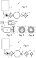
- FIG. 1 illustrates an example embodiment of a food apparatus for reversing or breaking an oil-in-water emulsion food product.
- the food apparatus 1 may include a container 2 for holding an oil-in-water emulsion food product.
- the oil-in-water emulsion food product may be delivered from a container that is not part of the apparatus 1.
- a conduit 3 connects the container 2 to the inlet of a feed pump 5.
- the outlet of the feed pump 5 is connected by a conduit to the inlet of a first heat exchanger 7, such as for example, but not limited to, a plate heat exchanger, tubular heat exchanger or scraped surface heat exchanger. All of the components are suitable for use with food products, i.e.
- the apparatus and its components are designed, fabricated, constructed, and installed according to sound sanitary design principles.
- This apparatus is designed and constructed so that it can be adequately cleaned and sanitized, and its surfaces are resistant to daily exposure to corrosive food products and cleaning/sanitizing chemicals.
- the outlet of the first heat exchanger 7 is connected by a conduit to an inlet of a cavitator 10.
- An outlet of the cavitator 10 is connected by a conduit to the inlet of a second heat exchanger 15.
- a backpressure valve 13 is arranged in the conduit connecting the outlet of the cavitator 10 to the inlet of the second heat exchanger 15.
- the second heat exchanger 15 is for example, but not limited to, a plate heat exchanger, tubular heat exchanger or scraped surface heat exchanger.
- the second heat exchanger 15 has an outlet that in the present embodiment forms the outlet of the apparatus 1.
- the described components of the apparatus 1 can be mounted on a frame or the like (not shown).
- temperature transmitters are located between the first heat exchanger 7 and the cavitator and at or just after the outlet of the second heat exchanger 15.
- a flow-meter such as for example a magnetic flow meter, is provided at a desired position between the outlet of the container 2 and the inlet of the second heat exchanger 15.
- pressure indicators are also provided.
- a least one pressure indicator is provided between the outlet of the feed pump 5 and the inlet of the cavitator 10.
- a pressure indicator between the feed pump 5 and the first heat exchanger 7 and between the first heat exchanger 7 and the cavitator 10.
- another pressure indicator is provided between the cavitator 10 and the second heat exchanger 15.
- the cavitator 10 according to the present invention a housing with a cavitation chamber 11 therein.
- a cavitator disk or wheel is rotatably suspended inside the cavitation chamber 11.
- the cavitation disk 12 is driven by an electric drive motor 14, such as for example an AC or DC drive motor for spinning the cavitator disk at a desired rotational speed.
- a frequency converter 18 controls the DC motor 14.
- a controller 20, such as an electronic control unit receives the signals from the temperature sensors, the pressure sensors, the flow sensor and from a control panel 25 with a user interface that can be used by an operator.
- the controller 20 sends information from the sensors to the control panel 25 and the control panel 25 may in an embodiment be provided with a display to show the sensor information to an operator.
- the controller 20 also sends a DC motor speed control signal to the frequency controller 18.
- the rotational speed of the cavitator 14 is controlled manually with a fixed speed, independent of the controller 20 signal received.
- FIG. 3 is a cross-sectional view of the cavitator 10 showing the outline of the cavitator disk or el 12 according to one embodiment.
- the cavitator disk 12 is provided with a plurality of radially extending slots that cause controlled hydrodynamic cavitation in the fluid inside the cavitation chamber 11 when the cavitator disk 12 is spinning.
- FIG. 4 is a cross-sectional view of the cavitator 10 showing the outline of the cavitator disk or wheel 12 according to another embodiment.
- the cavitator disk 12 is provided with a plurality of holes (circular holes are shown, but elliptical or similar shapes are also possible) that cause controlled hydrodynamic cavitation in the fluid inside the cavitation chamber 11 when the cavitator disk 12 is spinning.
- the apparatus used in the inventive methods and systems can be useful for reversing or breaking an oil-in-water emulsion food product.
- the oil-in-water emulsion food product contained in the container 2 flows through conduit 3 to the inlet of the feed pump 5.
- the feed pump 5 feeds oil-in-water emulsion food product to the first heat exchanger 7, thereby causing a continuous flow of liquid through the apparatus 1.
- a heating fluid such as for example water or steam, with a controlled temperature and flow rate flows also through the first heat exchanger 7.
- the oil-in-water emulsion is tempered to a desired temperature.
- the oil-in-water emulsion is pasteurized and then tempered by means of the first heat exchanger 7. From the first heat exchanger 7 the oil-in-water emulsion food product is pumped/fed to the hydrodynamic cavitation device 10 where it is subjected to hydrodynamic cavitation.
- the cavitator 10 can be the APVTM Cavitator sold and manufactured by SPX® Corporation, Charlotte, North Carolina, USA.
- the impact from the cavitation exposure either breaks or reverses the emulsion, leading to a continuous production of a single water-in-oil emulsion food product or to a continuous production of a single liquid wherein the watery component and the oily component previously forming the emulsion are no longer dispersed in one another, but phase-separated food product.
- the reversal or breaking up process is controlled by the e.g. the temperature of the oil-in-water emulsion entering the cavitator 10 and by the backpressure of the emulsion or the phase-separated emulsion leaving the cavitator 10. The process is also dependent on the composition of the oil-in-water emulsion, the temperature profile, the flow rate and on the characteristics and operation of the cavitator 10.
- the single water-in-oil emulsion food product or the single phase-separated emulsion food product with a watery component and an oily component is pumped/fed via the backpressure valve 13 to the second heat exchanger 15.
- the backpressure valve 13 regulates the pressure of the fluid coming into the back pressure valve.
- the backpressure valve 13 is connected to the controller 20 and an operator can select the setting for the backpressure valve 13 via the operator panel 25.
- the reversed emulsion or phase-separated emulsion is cooled by means of the second heat exchanger 15.
- a cooling fluid such as e.g. water, with a controlled temperature and flow rate is also flowed through the second heat exchanger 15.
- the cavitation is used to reverse or break the oil-in-water emulsion food product into a single water-in-oil emulsion food product.
- the single food product emulsion coming out of the cavitator 10 and coming out of the apparatus has the same fat content and the same water content as the ingoing oil-in-water emulsion since the oily content and the watery content of the ingoing oil-in-water emulsion are not separated.
- This allows the production of a water-in-oil emulsion food product, such as e.g. a low fat butter in one step from cream.
- the fat content and the water content of the resulting low fat butter will be the same as the fat content and the water content of the ingoing cream.
- a cream with a fat content of 48% (double cream) is pasteurized and tempered to approximately 15°C (10 - 20°C range) in the first heat exchanger 7 and pumped at 1800 L/H into the cavitation unit 10 (where it is reversed and a continuous production of low-fat butter is produced (water-in-oil emulsion).
- the backpressure leaving the cavitator 10 is within the range of 0,5 to 7,5 bar, preferably in the range of 1,5 to 5 bar. There is no separation of buttermilk, and thus a continuous flow of low fat (high water) butter comes out of the outlet of the second heat exchanger 15.
- vegetable oil is added to mix into the emulsion either before or after the reversal in the cavitator 10 in order to create a more flat crystallization profile that again will lead to a more stable product.
- a low-fat spread emulsion is reversed in the cavitator 10 before the crystallization of the fat.
- the emulsion is thereafter crystalized in a scraped surface heat exchanger, such as the Perfector line of scraped surface heat exchangers sold by Gerstenberg Schröder, a part of SPX® Corporation.
- oil-in-water emulsion is fed directly in to the cavitator 10, without any heat exchangers 7,15 before and after the cavitator 10 and/or without the back pressure valve 13 after the cavitator.
- the feed pump 5 is omitted, e.g. when if the cavitator 10 is fed by other means like gravity or from a pressurized tank.
- the oil-in-water emulsion food product that is fed to the cavitator 10 has a fat content range of 25 - 65%, preferably 35% to 50% and even more preferably 40% to 45%.
- the water-in-oil emulsion leaving the cavitator has the same fat content as the oil-in-water emulsion that is fed to the cavitator
- the oil-in-water emulsion food product that is fed to the cavitator 10 is a double cream, preferably a 48% double cream.
- the oil in the oil-in-water emulsion that is fed to the cavitator may be an animal fat or vegetable fat or a mixture of animal fat and vegetable fat.
- the animal fat or vegetable fat is liquid, solid, inter-esterified, fractionated or hydrogenated.
- the emulsion pumped to the cavitator 10 contains water, milk, cream, and/or recombined liquids
- FIG. 5 another embodiment of the apparatus 1 is shown for reversing an oil-in-water emulsion food product and separating the liquid phases.
- the apparatus shown in FIG. 5 is essentially identical to the apparatus shown in FIG. 1 , except that a separator 16 has been added after the second heat exchanger 15.
- the outlet of the second heat exchanger is connected by a conduit to the inlet of a separator 16 that has two outlets, one for each phase of the phase-separated emulsion.
- cream is pumped by the feed pump 5 from the container 2, through the first heat exchanger 7 and into the cavitator 10.
- the cream is tempered by the first heat exchanger 7 and the cream is broken into butter fat and butter milk in the cavitator 10 (such as e.g. the APVTM Cavitator sold and manufactured by SPX® Corporation, Charlotte, North Carolina, USA).
- the phase-separated liquid flows from the cavitator 10 via the backpressure valve 13 to the second heat exchanger 15 where it is cooled. From the second heat exchanger 15 the phase-separated liquid flows to the separator 16 and a continuous flow of buttermilk comes out of one of the outlets of the separator 16 and a continuous flow of butter fat comes out of the other outlet of the separator 16.
- the cavitator 10 is provided with two outlets and the separation of the two fluids is performed in the cavitator 10.
- the cavitator and the separator are combined into one integrated machine.
- the first heat exchanger 7 and the second heat exchanger 15 are one and the same so that the waste heat from the product downstream of the cavitator is reused for heating the product fed to the cavitator 10
- the separator 16 can also work without a cooler 15 after the cavitator 10.
- the heat exchanger 15 can in an embodiment be a heater, since oil (not butter) is more efficient separated in a separator at high temperatures due to lower oil viscosities.
- the invention has numerous advantages. Different embodiments or implementations may yield one or more of the following advantages. It should be noted that this is not an exhaustive list and there may be other advantages which are not described herein.
- One advantage of the invention is that it provides a simple method with only one step and continuous processing for reversing or breaking an oil-in-water emulsion food product and turning it into a single water-in-oil emulsion food product. It is another advantage of the invention that it leaves a small footprint. It is yet another advantage of the invention that it provides for an apparatus and method with low maintenance cost. It is yet another advantage of the invention that it provides for lower operating expenses for reversing or breaking an oil-in-water emulsion food product.
Landscapes
- Life Sciences & Earth Sciences (AREA)
- Chemical & Material Sciences (AREA)
- Engineering & Computer Science (AREA)
- Food Science & Technology (AREA)
- Polymers & Plastics (AREA)
- Animal Husbandry (AREA)
- Environmental Sciences (AREA)
- Oil, Petroleum & Natural Gas (AREA)
- Health & Medical Sciences (AREA)
- Nutrition Science (AREA)
- Chemical Kinetics & Catalysis (AREA)
- Edible Oils And Fats (AREA)
Description
- The present invention relates generally to reversing or breaking an oil-in-water emulsion food products. More particularly, the present invention relates to a method and an apparatus for reversing or breaking an oil-in-water emulsion food product.
- Conventional methods for breaking or reversing an oil-in-water emulsion food products are e.g. used in the making of butter.
In known methods, the cream (oil-in-water emulsion) is fed into a churning cylinder fitted with beaters that are driven by a variable speed motor.
Breaking up of the cream takes place in the cylinder and, when finished, the butter grains and buttermilk (that are now separate emulsions) pass on to a draining section. The first washing of the butter grains sometimes takes place en route - either with water or recirculated chilled buttermilk. The working of the butter commences in the draining section by means of a screw, which also conveys it to the next stage.
On leaving the working section, the butter passes through a conical channel to remove any remaining buttermilk. Immediately afterwards, the butter may be given its second washing, this time by two rows of adjustable highpressure nozzles. The water pressure is so high that the ribbon of butter is broken down into grains and consequently any residual milk solids are effectively removed.
In the final or mixing section the butter passes a series of perforated disks and star wheels. There is also an injector for final adjustment of the water content. Once regulated, the water content of the butter deviates less than +/- 0.1%, provided the characteristics of the cream remain the same.
The finished butter is discharged in a continuous ribbon from the end nozzle of the machine and then into the packaging unit.EP 0 199 398 A1 discloses an apparatus and a method for the continuous reversal of an oil-in-water emulsion food product, the method comprising feeding a flow of tempered oil-in-water emulsion into aheat exchanger 1 having astator 3 and arotor 2, agitating the tempered oil-in-water emulsion food product inside saidheat exchanger 1, thereby reversing the oil-in-water emulsion food product to a water-in-oil emulsion food product and discharging a reversed water-in-oil emulsion food product from theheat exchanger 1.US 3,332,615 discloses an apparatus and method for separating cream from milk. The concentrated cream is further processed by the apparatus by exposure to cavitation in order to produce butter oil and butter milk as separate products. This apparatus is relatively complicated and focused on producing butter oil, i.e. the watery contend of the cream is removed to a large extent from the oily part. - Accordingly, it is desirable to provide a method and an apparatus that is simpler and less costly than known technologies. Further, it is desirable to provide a completely new process for making products such as low fat butter, butter blends, low fat spreads and butter by emulsion breakage or reversal, by keeping substantially all of the watery product in the oily product, i.e. without separating the oily product and the watery product.
- The present invention offers a new simpler way of reversing or breaking oil-in-water emulsion food products where the oily product and the watery product that go into the process are together in one emulsion at the outcome of the process, in order to produce e.g. low fat spread thus eliminating the butter fat production step and subsequent addition to a low fat butter emulsion.
The foregoing needs are met, to a great extent, by the embodiments of the present invention.
In one aspect a method is provided for continuous reversal or breaking of an oil-in-water emulsion food product. In an embodiment the method comprises feeding a continuous flow of tempered oil-in-water emulsion food product into a cavitator with a cavitator disk that is rotatably suspended inside a cavitation chamber, causing cavitation in the tempered oil-in-water emulsion food product inside the cavitator thereby breaking the oil-in-water emulsion food product or thereby reversing the oil-in-water emulsion food product to a water-in-oil emulsion food product, and discharging a continuous flow of broken oil-in-water emulsion food product or a continuous flow of reversed water-in-oil emulsion food product out of the cavitator. Thus, a continuous flow of a low fat reversed or broken emulsion food product is the only product coming out of the cavitator and because the watery part has not been separated from the oily part the resulting food product emulsion has a high water content and thus a low fat content. - According to another aspect, the tempered oil-in-water emulsion that is fed to the cavitator is reversed into water-in-oil emulsion by hydrodynamic cavitation inside the cavitator and a single continuous flow of water-in-oil emulsion is produced with the cavitator.
- According to another aspect, the tempered oil-in-water emulsion that is fed to the cavitator is broken inside the cavitator and the liquid discharged from the cavitator has an oily liquid component and a watery liquid component that are not dispersed in one another.
- According to another aspect, the method further comprising adding and mixing vegetable oil into the emulsion either before or after the reversal in order to create a more flat crystallization profile of the resulting emulsion.
- According to another aspect, the continuous flow of water-in-oil emulsion coming out of the cavitator is cooled.
- According to another aspect, the oil-in-water emulsion that is pumped into the cavitator is pasteurized before entering the cavitator.
- According to another aspect, the backpressure of the emulsion leaving the cavitator is within the range of 0,5 to 7,5 bar, preferably 1,5 to 5 bar.
- According to another aspect, the oil-in-water emulsion that is pumped to the cavitator has a fat content in the range of 25 to 65%.
According to another aspect, the oil in the oil-in-water emulsion is an animal fat or vegetable fat or a mixture of animal fat and vegetable fat.
According to another aspect, the animal fat or vegetable fat is liquid, solid, inter-esterified, fractionated or hydrogenated.
According to another aspect, the emulsion fed to the cavitator contains water, milk, cream, and /or recombined liquids.
According to another aspect, the resulting water-in-oil emulsion is butter or margarine, preferably a low fat butter or low fat margarine.
According to another aspect, the emulsion fed to the cavitator is a cream that is broken in the cavitator into butter fat and buttermilk, and said method preferably includes further separating the flow of fluid coming from the cavitator into a continuous flow of butter and a continuous flow of buttermilk.
According to another aspect, the emulsion fed to the cavitator is a low-fat spread emulsion wherein the fat has not yet crystallized, and the low-fat spread emulsion is broken inside the cavitator. The use of cavitation instead of conventional methods, e.g. beating, for reversing or breaking an oil-in-water emulsion is simpler and less costly than known technologies.
According to an aspect, the cavitation is used in a continuous flow of oil-in-water emulsion to produce a continuous flow of broken oil-in-water emulsion or to produce a flow of water-in-oil emulsion.
In another aspect of the invention, an apparatus for reversing or breaking an oil-in-water emulsion is provided. In an embodiment the apparatus for breaking or reversing an oil-in-water emulsion comprises a source of pressurized oil-in-water emulsion, a cavitator with cavitation chamber, and with a cavitator disk that rotatably suspended inside the cavitation chamber, the cavitation chamber being provided with an inlet and with an outlet, the inlet being in fluid connection with the source of pressurized oil-in-water emulsion, a first heat exchanger for tempering a flow of oil-in-water emulsion flowing to the inlet of the cavitator, a second heat exchanger for cooling the emulsion that is discharged from the outlet of the cavitator.
According to another aspect, the cavitator is configured for breaking the oil-in-water emulsion in the cavitator chamber or configured for reversing the oil-in-water emulsion in the cavitation chamber.
According to yet another aspect, the apparatus further comprises a backpressure valve arranged downstream of the cavitator and configured for maintaining a desired backpressure at the outlet of said cavitator so that said oil-in-water emulsion is either reversed or broken in said cavitator.
According to yet another aspect, the apparatus further comprises a separator for separating a continuous flow of broken emulsion into a continuous flow of watery liquid and a continuous flow of an oily liquid.
There has thus been outlined, rather broadly, certain embodiments of the invention in order that the detailed description thereof herein may be better understood, and in order that the present contribution to the art may be better appreciated. There are, of course, additional embodiments of the invention that will be described below and which will form the subject matter of the claims appended hereto. - In the following detailed portion of the present description, the invention will be explained in more detail with reference to the exemplary embodiments shown in the drawings, in which:
-
FIG. 1 is a diagrammatic view of an apparatus for reversing or breaking an oil-in-water emulsion according to an example embodiment of the present invention, -
FIG. 2 is a sectional diagrammatic view of a cavitator of the apparatus shown inFIG. 1 and an electric drive motor operably coupled to the cavitator, -
FIG. 3 is a cross-sectional view of the cavitator ofFIG. 1 in a first example embodiment, -
FIG. 4 is a cross-sectional view of the cavitator ofFIG. 1 in a second example embodiment, and -
FIG. 5 is a diagrammatic view of an apparatus for reversing or breaking an oil-in-water emulsion according toFIG. 1 with an additional separator. - Example embodiments of the invention will now be described with reference to the drawing figures, in which like reference numerals refer to like parts throughout. An embodiment in accordance with the present invention provides a food apparatus for reversing or breaking an oil-in-water emulsion food product.
-
FIG. 1 illustrates an example embodiment of a food apparatus for reversing or breaking an oil-in-water emulsion food product. Thefood apparatus 1 may include acontainer 2 for holding an oil-in-water emulsion food product. In other embodiments, the oil-in-water emulsion food product may be delivered from a container that is not part of theapparatus 1. Aconduit 3 connects thecontainer 2 to the inlet of afeed pump 5. The outlet of thefeed pump 5 is connected by a conduit to the inlet of afirst heat exchanger 7, such as for example, but not limited to, a plate heat exchanger, tubular heat exchanger or scraped surface heat exchanger. All of the components are suitable for use with food products, i.e. the apparatus and its components are designed, fabricated, constructed, and installed according to sound sanitary design principles. This apparatus is designed and constructed so that it can be adequately cleaned and sanitized, and its surfaces are resistant to daily exposure to corrosive food products and cleaning/sanitizing chemicals. - The outlet of the
first heat exchanger 7 is connected by a conduit to an inlet of acavitator 10. An outlet of thecavitator 10 is connected by a conduit to the inlet of asecond heat exchanger 15. Abackpressure valve 13 is arranged in the conduit connecting the outlet of thecavitator 10 to the inlet of thesecond heat exchanger 15. - The
second heat exchanger 15 is for example, but not limited to, a plate heat exchanger, tubular heat exchanger or scraped surface heat exchanger. Thesecond heat exchanger 15 has an outlet that in the present embodiment forms the outlet of theapparatus 1.
In an embodiment, the described components of theapparatus 1 can be mounted on a frame or the like (not shown).
In an embodiment, temperature transmitters (sensors) are located between thefirst heat exchanger 7 and the cavitator and at or just after the outlet of thesecond heat exchanger 15. In an embodiment, a flow-meter, such as for example a magnetic flow meter, is provided at a desired position between the outlet of thecontainer 2 and the inlet of thesecond heat exchanger 15. In an embodiment, pressure indicators (sensors) are also provided. A least one pressure indicator (sensor) is provided between the outlet of thefeed pump 5 and the inlet of thecavitator 10. In an embodiment, there is provided a pressure indicator (sensor) between thefeed pump 5 and thefirst heat exchanger 7 and between thefirst heat exchanger 7 and thecavitator 10. In an embodiment, another pressure indicator is provided between the cavitator 10 and thesecond heat exchanger 15. In an embodiment there are also temperature transmitters (sensors) in thecontainer 2, alongconduit 3, and in between the cavitator 10 and thesecond heat exchanger 15.
As more particularly shown inFIG. 2 , thecavitator 10 according to the present invention a housing with acavitation chamber 11 therein. A cavitator disk or wheel is rotatably suspended inside thecavitation chamber 11. In an embodiment, thecavitation disk 12 is driven by anelectric drive motor 14, such as for example an AC or DC drive motor for spinning the cavitator disk at a desired rotational speed. Afrequency converter 18 controls theDC motor 14. Acontroller 20, such as an electronic control unit receives the signals from the temperature sensors, the pressure sensors, the flow sensor and from acontrol panel 25 with a user interface that can be used by an operator. Thecontroller 20 sends information from the sensors to thecontrol panel 25 and thecontrol panel 25 may in an embodiment be provided with a display to show the sensor information to an operator. Thecontroller 20 also sends a DC motor speed control signal to thefrequency controller 18. According to another embodiment the rotational speed of thecavitator 14 is controlled manually with a fixed speed, independent of thecontroller 20 signal received.FIG. 3 is a cross-sectional view of thecavitator 10 showing the outline of the cavitator disk orel 12 according to one embodiment. In this embodiment, thecavitator disk 12 is provided with a plurality of radially extending slots that cause controlled hydrodynamic cavitation in the fluid inside thecavitation chamber 11 when thecavitator disk 12 is spinning.
FIG. 4 is a cross-sectional view of thecavitator 10 showing the outline of the cavitator disk orwheel 12 according to another embodiment. In this embodiment, thecavitator disk 12 is provided with a plurality of holes (circular holes are shown, but elliptical or similar shapes are also possible) that cause controlled hydrodynamic cavitation in the fluid inside thecavitation chamber 11 when thecavitator disk 12 is spinning. - As otherwise discussed herein, the apparatus used in the inventive methods and systems can be useful for reversing or breaking an oil-in-water emulsion food product.
Returning toFIG. 1 , the oil-in-water emulsion food product contained in thecontainer 2 flows throughconduit 3 to the inlet of thefeed pump 5. Thefeed pump 5 feeds oil-in-water emulsion food product to thefirst heat exchanger 7, thereby causing a continuous flow of liquid through theapparatus 1. A heating fluid, such as for example water or steam, with a controlled temperature and flow rate flows also through thefirst heat exchanger 7. In the first heat exchanger, the oil-in-water emulsion is tempered to a desired temperature. In an embodiment, the oil-in-water emulsion is pasteurized and then tempered by means of thefirst heat exchanger 7.
From thefirst heat exchanger 7 the oil-in-water emulsion food product is pumped/fed to thehydrodynamic cavitation device 10 where it is subjected to hydrodynamic cavitation. Thecavitator 10 can be the APV™ Cavitator sold and manufactured by SPX® Corporation, Charlotte, North Carolina, USA. The impact from the cavitation exposure either breaks or reverses the emulsion, leading to a continuous production of a single water-in-oil emulsion food product or to a continuous production of a single liquid wherein the watery component and the oily component previously forming the emulsion are no longer dispersed in one another, but phase-separated food product. The reversal or breaking up process is controlled by the e.g. the temperature of the oil-in-water emulsion entering thecavitator 10 and by the backpressure of the emulsion or the phase-separated emulsion leaving thecavitator 10. The process is also dependent on the composition of the oil-in-water emulsion, the temperature profile, the flow rate and on the characteristics and operation of thecavitator 10. - From the outlet of the
cavitator 10, the single water-in-oil emulsion food product or the single phase-separated emulsion food product with a watery component and an oily component is pumped/fed via thebackpressure valve 13 to thesecond heat exchanger 15. Thebackpressure valve 13 regulates the pressure of the fluid coming into the back pressure valve. Thebackpressure valve 13 is connected to thecontroller 20 and an operator can select the setting for thebackpressure valve 13 via theoperator panel 25. - The reversed emulsion or phase-separated emulsion is cooled by means of the
second heat exchanger 15. Hereto, a cooling fluid, such as e.g. water, with a controlled temperature and flow rate is also flowed through thesecond heat exchanger 15. - Thus, the cavitation is used to reverse or break the oil-in-water emulsion food product into a single water-in-oil emulsion food product. The single food product emulsion coming out of the
cavitator 10 and coming out of the apparatus has the same fat content and the same water content as the ingoing oil-in-water emulsion since the oily content and the watery content of the ingoing oil-in-water emulsion are not separated. This allows the production of a water-in-oil emulsion food product, such as e.g. a low fat butter in one step from cream. The fat content and the water content of the resulting low fat butter will be the same as the fat content and the water content of the ingoing cream. - As an example of a method according to an embodiment of the invention, a cream with a fat content of 48% (double cream) is pasteurized and tempered to approximately 15°C (10 - 20°C range) in the
first heat exchanger 7 and pumped at 1800 L/H into the cavitation unit 10 (where it is reversed and a continuous production of low-fat butter is produced (water-in-oil emulsion). The backpressure leaving thecavitator 10 is within the range of 0,5 to 7,5 bar, preferably in the range of 1,5 to 5 bar. There is no separation of buttermilk, and thus a continuous flow of low fat (high water) butter comes out of the outlet of thesecond heat exchanger 15. - In an embodiment, vegetable oil is added to mix into the emulsion either before or after the reversal in the
cavitator 10 in order to create a more flat crystallization profile that again will lead to a more stable product. - In another embodiment a low-fat spread emulsion is reversed in the
cavitator 10 before the crystallization of the fat. The emulsion is thereafter crystalized in a scraped surface heat exchanger, such as the Perfector line of scraped surface heat exchangers sold by Gerstenberg Schröder, a part of SPX® Corporation. - In another embodiment the oil-in-water emulsion is fed directly in to the
cavitator 10, without anyheat exchangers cavitator 10 and/or without theback pressure valve 13 after the cavitator. Also, in an embodiment thefeed pump 5 is omitted, e.g. when if thecavitator 10 is fed by other means like gravity or from a pressurized tank. - In an embodiment, the oil-in-water emulsion food product that is fed to the
cavitator 10 has a fat content range of 25 - 65%, preferably 35% to 50% and even more preferably 40% to 45%. The water-in-oil emulsion leaving the cavitator has the same fat content as the oil-in-water emulsion that is fed to the cavitator - In another embodiment, the oil-in-water emulsion food product that is fed to the
cavitator 10 is a double cream, preferably a 48% double cream. - In an embodiment, the oil in the oil-in-water emulsion that is fed to the cavitator may be an animal fat or vegetable fat or a mixture of animal fat and vegetable fat. In an embodiment, the animal fat or vegetable fat is liquid, solid, inter-esterified, fractionated or hydrogenated.
- In an embodiment, the emulsion pumped to the
cavitator 10 contains water, milk, cream, and/or recombined liquids - Turning now to
FIG. 5 , another embodiment of theapparatus 1 is shown for reversing an oil-in-water emulsion food product and separating the liquid phases. The apparatus shown inFIG. 5 is essentially identical to the apparatus shown inFIG. 1 , except that aseparator 16 has been added after thesecond heat exchanger 15. The outlet of the second heat exchanger is connected by a conduit to the inlet of aseparator 16 that has two outlets, one for each phase of the phase-separated emulsion. - In an embodiment, cream is pumped by the
feed pump 5 from thecontainer 2, through thefirst heat exchanger 7 and into thecavitator 10. The cream is tempered by thefirst heat exchanger 7 and the cream is broken into butter fat and butter milk in the cavitator 10 (such as e.g. the APV™ Cavitator sold and manufactured by SPX® Corporation, Charlotte, North Carolina, USA). The phase-separated liquid flows from thecavitator 10 via thebackpressure valve 13 to thesecond heat exchanger 15 where it is cooled. From thesecond heat exchanger 15 the phase-separated liquid flows to theseparator 16 and a continuous flow of buttermilk comes out of one of the outlets of theseparator 16 and a continuous flow of butter fat comes out of the other outlet of theseparator 16.
In an embodiment thecavitator 10 is provided with two outlets and the separation of the two fluids is performed in thecavitator 10. Alternatively, the cavitator and the separator are combined into one integrated machine.
In an embodiment thefirst heat exchanger 7 and thesecond heat exchanger 15 are one and the same so that the waste heat from the product downstream of the cavitator is reused for heating the product fed to thecavitator 10
Theseparator 16 can also work without a cooler 15 after thecavitator 10. Theheat exchanger 15 can in an embodiment be a heater, since oil (not butter) is more efficient separated in a separator at high temperatures due to lower oil viscosities. - The invention has numerous advantages. Different embodiments or implementations may yield one or more of the following advantages. It should be noted that this is not an exhaustive list and there may be other advantages which are not described herein. One advantage of the invention is that it provides a simple method with only one step and continuous processing for reversing or breaking an oil-in-water emulsion food product and turning it into a single water-in-oil emulsion food product. It is another advantage of the invention that it leaves a small footprint. It is yet another advantage of the invention that it provides for an apparatus and method with low maintenance cost. It is yet another advantage of the invention that it provides for lower operating expenses for reversing or breaking an oil-in-water emulsion food product. It is yet another advantage of the invention that it provides improved product quality of reversed or broken oil-in-water emulsion food product. It is yet another advantage of the invention that it provides for flexible production of reversed or broken oil-in-water emulsion food product. It is yet another advantage of the invention that it provides for a low fat butter.
Claims (14)
- A method for continuous reversal or breaking of an oil-in-water emulsion food product, said method comprising:feeding a continuous flow of tempered oil-in-water emulsion food product into a cavitator (10) with a cavitator disk (12) that is rotatably suspended inside a cavitation chamber (11), causing cavitation in the tempered oil-in-water emulsion food product inside said cavitator (10) thereby breaking the oil-in-water emulsion food product or thereby reversing the oil-in-water emulsion food product to a water-in-oil emulsion food product,discharging a single continuous flow of broken oil-in-water emulsion food product or a single continuous flow of reversed water-in-oil emulsion food product from said cavitator (10).
- The method according to claim 1, wherein the tempered oil-in-water emulsion food product that is fed to the cavitator (10) is reversed into a water-in-oil emulsion food product by hydrodynamic cavitation inside the cavitator (10) and a single continuous flow of water-in-oil emulsion food product is coming out of said cavitator (10).
- A method according to claim 1 or 2, further comprising adding and mixing vegetable oil into the emulsion either before or after the reversal in order to create a more flat crystallization profile of the resulting emulsion.
- The method according to claim 1, wherein the tempered oil-in-water emulsion food product that is fed to the cavitator (10) is broken inside the cavitator (10) and the phase-separated emulsion food product that flows out of the cavitator (10) has an oily liquid component and a watery liquid component with the oily component and the watery component in a single emulsion.
- The method according to any one of the preceding claims, wherein the single continuous flow of water-in-oil emulsion food product coming out of said cavitator (10) is cooled.
- The method according to claim 1 or 2, wherein the oil-in-water emulsion food product that is fed into the cavitator (10) is pasteurized before entering the cavitator (10).
- A method according to any of the preceding claims, wherein the backpressure of the emulsion leaving the cavitator (10) is within the range of 0,5 to 7,5 bar, preferably 1,5 to 5 bar.
- A method according to any one of the preceding claims, wherein the oil-in-water emulsion food product that is fed to the cavitator (10) has a fat content in the range of 25 to 80%.
- A method according to any one of the preceding claims, wherein the water-in-oil emulsion food product coming out of the cavitator (10) has a fat content that is equal to the fat content of the oil-in-water emulsion food product that is fed to the cavitator (10).
- A method according to any one of the preceding claims, wherein the oil in the oil-in-water emulsion comprises an animal fat or vegetable fat or a mixture of animal fat and vegetable fat, preferably said animal fat or vegetable fat is liquid, solid, inter-esterified, fractionated or hydrogenated, and/or wherein the emulsion fed to the cavitator (10) contains water, milk, cream, and/or recombined liquids, and/or wherein the resulting water-in-oil emulsion is a low-fat butter or low-fat margarine.
- A method according to any one of claims 3 to 10, wherein the emulsion fed to the cavitator (10) is a low-fat spread emulsion wherein the fat has not yet crystallized, and the low-fat spread emulsion is broken inside the cavitator (10).
- An apparatus (1) for breaking or reversing an oil-in-water emulsion food product, said apparatus (1) comprising:a source of pressurized oil-in-water emulsion food product,a cavitator (10) with cavitation chamber (11) with a cavitator disk (12) that is rotatably suspended inside said cavitation chamber, said cavitation chamber being provided with an inlet and with an outlet, said inlet being in fluid connection with said source of pressurized oil-in-water emulsion food product,a first heat exchanger (7) for tempering a flow of oil-in-water emulsion food product flowing to the inlet of said cavitator (10),a second heat exchanger (15) for cooling the emulsion that is discharged from the outlet of said cavitator (10).
- An apparatus (1) according to claim 12, wherein said cavitator (10) is configured for breaking the oil-in-water emulsion in the cavitation chamber (11) into a single water-in-oil emulsion or configured for reversing the oil-in-water emulsion in the cavitation chamber (11) into a single water-in-oil emulsion.
- An apparatus (1) according to claim 12 or 13, further comprising a backpressure valve (13) arranged downstream of the cavitator (10) and configured for maintaining a desired backpressure at the outlet of said cavitator (10) so that said oil-in-water emulsion food product is either reversed or broken in said cavitator (10).
Applications Claiming Priority (2)
| Application Number | Priority Date | Filing Date | Title |
|---|---|---|---|
| DKPA201200566A DK177609B1 (en) | 2012-09-14 | 2012-09-14 | Method for Continuously Reversing or Breaking an Oil-in-Water Emulsion by Hydrodynamic Cavitation |
| PCT/EP2013/068443 WO2014040918A1 (en) | 2012-09-14 | 2013-09-06 | Method, use and apparatus for continuous reversal or breaking of an oil-in-water emulsion food product by means of hydrodynamic cavitation |
Publications (2)
| Publication Number | Publication Date |
|---|---|
| EP2895002A1 EP2895002A1 (en) | 2015-07-22 |
| EP2895002B1 true EP2895002B1 (en) | 2017-09-06 |
Family
ID=49118517
Family Applications (1)
| Application Number | Title | Priority Date | Filing Date |
|---|---|---|---|
| EP13759185.5A Active EP2895002B1 (en) | 2012-09-14 | 2013-09-06 | Method, use and apparatus for continuous reversal or breaking of an oil-in-water emulsion food product by means of hydrodynamic cavitation |
Country Status (6)
| Country | Link |
|---|---|
| US (1) | US20150230423A1 (en) |
| EP (1) | EP2895002B1 (en) |
| AU (1) | AU2013314450B2 (en) |
| DK (2) | DK177609B1 (en) |
| NZ (1) | NZ706394A (en) |
| WO (1) | WO2014040918A1 (en) |
Families Citing this family (4)
| Publication number | Priority date | Publication date | Assignee | Title |
|---|---|---|---|---|
| FI127870B (en) | 2015-08-31 | 2019-04-15 | Valio Oy | Microparticulated ideal whey protein preparation, process for its preparation and its use |
| WO2017097505A1 (en) * | 2015-12-11 | 2017-06-15 | Unilever N.V. | Process for preparing fat continuous emulsions on a small scale |
| JP7175088B2 (en) * | 2017-03-01 | 2022-11-18 | 株式会社明治 | Fresh cream and its manufacturing method |
| PL4093535T3 (en) * | 2020-01-23 | 2024-10-28 | Raptech Eberswalde Gmbh | Method for producing a stable hydrocarbon-water dispersion for improving combustion processes, and a water-hydrocarbon dispersion that is easily separable into at least two phases as part of the clean-up process at accident locations |
Family Cites Families (45)
| Publication number | Priority date | Publication date | Assignee | Title |
|---|---|---|---|---|
| US1527586A (en) * | 1921-07-27 | 1925-02-24 | Pfaudler Co Inc | Method of deodorizing and preparing cream for butter making and the like |
| US1650625A (en) * | 1925-12-15 | 1927-11-29 | Laval Separator Co De | Butter-making apparatus |
| US2033121A (en) * | 1934-08-15 | 1936-03-10 | William H Ashton | Means and method for churning butter |
| US2612354A (en) * | 1951-05-24 | 1952-09-30 | Laval Separator Co De | Rotary mixer |
| US3109740A (en) * | 1959-08-18 | 1963-11-05 | Lakeville Creameries Inc | Butter churning apparatus and method |
| US3093482A (en) * | 1959-08-24 | 1963-06-11 | Cherry Burrell Corp | Butter making method |
| SE306870B (en) * | 1963-06-12 | 1968-12-09 | Separator Ab | |
| US3614069A (en) * | 1969-09-22 | 1971-10-19 | Fibra Sonics | Multiple frequency ultrasonic method and apparatus for improved cavitation, emulsification and mixing |
| LU60482A1 (en) * | 1970-03-09 | 1970-05-11 | ||
| US3937445A (en) * | 1974-02-11 | 1976-02-10 | Vito Agosta | Process and apparatus for obtaining the emulsification of nonmiscible liquids |
| US4118797A (en) * | 1977-10-25 | 1978-10-03 | Energy And Minerals Research Co. | Ultrasonic emulsifier and method |
| IT1119935B (en) * | 1979-09-11 | 1986-03-19 | Ferrero & C Spa P | SWEET PROTEIN FOOD PRODUCT IN FOAMED PLASTIC MASS FORM |
| GB2084171B (en) * | 1980-09-30 | 1984-10-24 | Unilever Plc | A process for producing a low-calorie spread |
| US4430251A (en) * | 1981-09-29 | 1984-02-07 | Hoffert Manufacturing Co., Inc. | High energy emulsifier |
| FI832413L (en) * | 1982-07-08 | 1984-01-09 | Unilever Nv | REDUCTION OF OVER FOUNDATION FOR FRESSING |
| US4441823A (en) * | 1982-07-19 | 1984-04-10 | Power Harold H | Static line mixer |
| DE3529677C1 (en) * | 1984-07-17 | 1986-09-11 | Westfalia Separator Ag, 4740 Oelde | Continuously operating buttermaking machine |
| US4840810A (en) * | 1985-03-27 | 1989-06-20 | Lever Brothers Company | Process for the preparation of an edible fat-containing product |
| US4675194A (en) * | 1986-03-03 | 1987-06-23 | Reaction Technology, Inc. | Sonic process for converting proteinaceous raw materials in situ into semi-solid food products |
| US5061456A (en) * | 1987-08-25 | 1991-10-29 | Stranco, Inc. | Polymer activation apparatus |
| EP0385542B1 (en) * | 1989-03-03 | 1993-10-27 | Unilever N.V. | Process for the preparation of a low calorie butter spread and products obtained by said process |
| GB8909803D0 (en) * | 1989-04-28 | 1989-06-14 | Unilever Plc | Process for spread production and apparatus for performance of the process |
| GB9322228D0 (en) * | 1993-10-28 | 1993-12-15 | Kodak Ltd | Homogenising heads |
| US5487913A (en) * | 1994-03-31 | 1996-01-30 | Creamery Hollow U.S.A., Inc. | Butter products |
| US5622650A (en) * | 1995-09-15 | 1997-04-22 | The Mead Corporation | Emulsifying milling machine and process for emulsifying |
| FR2748954B1 (en) * | 1996-05-21 | 1998-07-24 | Pavese Guy | HIGH PERFORMANCE ULTRA COLLOIDAL HOMOGENIZER-EMULSIFER MODULE FOR REPUTABLE NON-MISCIBLE FLUIDS AND ASSOCIATED METHOD |
| US5971601A (en) * | 1998-02-06 | 1999-10-26 | Kozyuk; Oleg Vyacheslavovich | Method and apparatus of producing liquid disperse systems |
| SK284280B6 (en) * | 1998-04-01 | 2004-12-01 | Unilever Nv | Process for preparing a spread |
| FR2808703B1 (en) * | 2000-05-09 | 2002-08-02 | Centre Nat Rech Scient | PROCESS FOR THE PREPARATION OF A DOUBLE MONODISPERSE EMULSION |
| US6627784B2 (en) * | 2000-05-17 | 2003-09-30 | Hydro Dynamics, Inc. | Highly efficient method of mixing dissimilar fluids using mechanically induced cavitation |
| US6406736B1 (en) * | 2001-03-12 | 2002-06-18 | Kraft Foods Holdings, Inc. | Process for making cream cheese products without whey separation |
| US7207712B2 (en) * | 2004-09-07 | 2007-04-24 | Five Star Technologies, Inc. | Device and method for creating hydrodynamic cavitation in fluids |
| US20110183050A1 (en) * | 2006-07-20 | 2011-07-28 | Brophy James S | Modification of particle morphology to improve product functionality |
| US8268136B2 (en) * | 2007-12-20 | 2012-09-18 | McCutchen, Co. | Electrohydraulic and shear cavitation radial counterflow liquid processor |
| US8042989B2 (en) * | 2009-05-12 | 2011-10-25 | Cavitation Technologies, Inc. | Multi-stage cavitation device |
| US9474301B2 (en) * | 2008-10-27 | 2016-10-25 | Cavitation Technologies, Inc. | Flow-through cavitation-assisted rapid modification of beverage fluids |
| EP2396396A4 (en) * | 2009-02-11 | 2013-05-01 | H R D Corp | High shear hydrogenation of wax and oil mixtures |
| SE0900233A1 (en) * | 2009-02-24 | 2010-08-25 | Tetra Laval Holdings & Finance | Diaphragm pump head for a homogenizer |
| EP2571968A1 (en) * | 2010-05-21 | 2013-03-27 | H R D Corporation | Process for upgrading low value renewable oils |
| CA2707287C (en) * | 2010-06-11 | 2012-02-07 | Van Miller | Spreadable butter formulations |
| DE102010023963A1 (en) * | 2010-06-16 | 2011-12-22 | Mars Inc. | Method and apparatus for producing a foamed meat or fish product |
| JP6367519B2 (en) * | 2010-12-15 | 2018-08-01 | 松本 高明 | Mixing device, mixed fluid manufacturing device, mixed fluid manufacturing method and mixed fluid manufactured thereby, and water and ice containing oxygen |
| EP2696696A1 (en) * | 2011-04-12 | 2014-02-19 | Danone, S.A. | Method for obtaining a fermented dairy product |
| US20130021868A1 (en) * | 2011-07-22 | 2013-01-24 | Doolin Michael B | Static Fluid Mixer and Method |
| US9126176B2 (en) * | 2012-05-11 | 2015-09-08 | Caisson Technology Group LLC | Bubble implosion reactor cavitation device, subassembly, and methods for utilizing the same |
-
2012
- 2012-09-14 DK DKPA201200566A patent/DK177609B1/en not_active IP Right Cessation
-
2013
- 2013-09-06 US US14/428,332 patent/US20150230423A1/en not_active Abandoned
- 2013-09-06 WO PCT/EP2013/068443 patent/WO2014040918A1/en not_active Ceased
- 2013-09-06 EP EP13759185.5A patent/EP2895002B1/en active Active
- 2013-09-06 AU AU2013314450A patent/AU2013314450B2/en not_active Ceased
- 2013-09-06 NZ NZ706394A patent/NZ706394A/en not_active IP Right Cessation
- 2013-09-06 DK DK13759185.5T patent/DK2895002T3/en active
Non-Patent Citations (1)
| Title |
|---|
| None * |
Also Published As
| Publication number | Publication date |
|---|---|
| DK2895002T3 (en) | 2017-12-18 |
| AU2013314450A1 (en) | 2015-04-09 |
| EP2895002A1 (en) | 2015-07-22 |
| NZ706394A (en) | 2017-09-29 |
| US20150230423A1 (en) | 2015-08-20 |
| DK177609B1 (en) | 2013-12-02 |
| AU2013314450B2 (en) | 2016-11-17 |
| WO2014040918A1 (en) | 2014-03-20 |
Similar Documents
| Publication | Publication Date | Title |
|---|---|---|
| US8512785B2 (en) | Device and a method for the micro-particulation of filter residues | |
| AU2013314450B2 (en) | Method, use and apparatus for continuous reversal or breaking of an oil-in-water emulsion food product by means of hydrodynamic cavitation | |
| US9358482B2 (en) | Filtration and dewatering apparatus | |
| US20170326516A1 (en) | Apparatuses and methods for improved mixing | |
| Meyer et al. | High concentration of skim milk proteins by ultrafiltration: Characterisation of a dynamic membrane system with a rotating membrane in comparison with a spiral wound membrane | |
| US20190350403A1 (en) | Device for heating milk or milk foam | |
| Goff | Dairy product processing equipment | |
| CN104135866B (en) | Apparatus and method for mixing edible mass | |
| RU2218491C2 (en) | Fluid media hydrodynamic treatment device | |
| EP2705759B1 (en) | Apparatus for continuous tempering of chocolate mass | |
| US2397488A (en) | Churn | |
| EP2083616B1 (en) | Butter making device | |
| EP1673989B1 (en) | Apparatus and method for treating food products | |
| EP1931214B1 (en) | Method and apparatus for making an air-containing mixture | |
| RU2421983C2 (en) | Milk complex treatment plant | |
| SU1757568A1 (en) | Butter manufacturing method | |
| US1368291A (en) | Method of treating viscous liquids | |
| RU2621996C1 (en) | Scalder of sugar beet chips | |
| WO2006131800A1 (en) | Food processing machine : aduk mixing unit | |
| DE102008012525A1 (en) | Method and device for separating fat from fatty dairy products, comprise separating different components of fatty dairy products from one another by bulk material and then gassing with air through supply component | |
| Badr et al. | A NEW MACHINE FOR PRODUCING BUTTER TO SUIT SMALL PROJECTS | |
| DEV0008167MA (en) |
Legal Events
| Date | Code | Title | Description |
|---|---|---|---|
| PUAI | Public reference made under article 153(3) epc to a published international application that has entered the european phase |
Free format text: ORIGINAL CODE: 0009012 |
|
| 17P | Request for examination filed |
Effective date: 20150414 |
|
| AK | Designated contracting states |
Kind code of ref document: A1 Designated state(s): AL AT BE BG CH CY CZ DE DK EE ES FI FR GB GR HR HU IE IS IT LI LT LU LV MC MK MT NL NO PL PT RO RS SE SI SK SM TR |
|
| AX | Request for extension of the european patent |
Extension state: BA ME |
|
| DAX | Request for extension of the european patent (deleted) | ||
| GRAP | Despatch of communication of intention to grant a patent |
Free format text: ORIGINAL CODE: EPIDOSNIGR1 |
|
| RIC1 | Information provided on ipc code assigned before grant |
Ipc: A23C 15/02 20060101AFI20170331BHEP Ipc: A23L 35/00 20160101ALI20170331BHEP Ipc: A01J 15/12 20060101ALI20170331BHEP Ipc: A23D 7/015 20060101ALI20170331BHEP Ipc: A23D 7/02 20060101ALI20170331BHEP |
|
| INTG | Intention to grant announced |
Effective date: 20170421 |
|
| GRAS | Grant fee paid |
Free format text: ORIGINAL CODE: EPIDOSNIGR3 |
|
| GRAA | (expected) grant |
Free format text: ORIGINAL CODE: 0009210 |
|
| AK | Designated contracting states |
Kind code of ref document: B1 Designated state(s): AL AT BE BG CH CY CZ DE DK EE ES FI FR GB GR HR HU IE IS IT LI LT LU LV MC MK MT NL NO PL PT RO RS SE SI SK SM TR |
|
| REG | Reference to a national code |
Ref country code: GB Ref legal event code: FG4D |
|
| REG | Reference to a national code |
Ref country code: CH Ref legal event code: EP Ref country code: AT Ref legal event code: REF Ref document number: 924884 Country of ref document: AT Kind code of ref document: T Effective date: 20170915 |
|
| REG | Reference to a national code |
Ref country code: IE Ref legal event code: FG4D |
|
| REG | Reference to a national code |
Ref country code: DE Ref legal event code: R096 Ref document number: 602013026206 Country of ref document: DE |
|
| REG | Reference to a national code |
Ref country code: NL Ref legal event code: FP |
|
| REG | Reference to a national code |
Ref country code: DK Ref legal event code: T3 Effective date: 20171212 |
|
| REG | Reference to a national code |
Ref country code: SE Ref legal event code: TRGR |
|
| REG | Reference to a national code |
Ref country code: LT Ref legal event code: MG4D |
|
| PG25 | Lapsed in a contracting state [announced via postgrant information from national office to epo] |
Ref country code: HR Free format text: LAPSE BECAUSE OF FAILURE TO SUBMIT A TRANSLATION OF THE DESCRIPTION OR TO PAY THE FEE WITHIN THE PRESCRIBED TIME-LIMIT Effective date: 20170906 Ref country code: FI Free format text: LAPSE BECAUSE OF FAILURE TO SUBMIT A TRANSLATION OF THE DESCRIPTION OR TO PAY THE FEE WITHIN THE PRESCRIBED TIME-LIMIT Effective date: 20170906 Ref country code: NO Free format text: LAPSE BECAUSE OF FAILURE TO SUBMIT A TRANSLATION OF THE DESCRIPTION OR TO PAY THE FEE WITHIN THE PRESCRIBED TIME-LIMIT Effective date: 20171206 Ref country code: LT Free format text: LAPSE BECAUSE OF FAILURE TO SUBMIT A TRANSLATION OF THE DESCRIPTION OR TO PAY THE FEE WITHIN THE PRESCRIBED TIME-LIMIT Effective date: 20170906 |
|
| REG | Reference to a national code |
Ref country code: AT Ref legal event code: MK05 Ref document number: 924884 Country of ref document: AT Kind code of ref document: T Effective date: 20170906 |
|
| PG25 | Lapsed in a contracting state [announced via postgrant information from national office to epo] |
Ref country code: LV Free format text: LAPSE BECAUSE OF FAILURE TO SUBMIT A TRANSLATION OF THE DESCRIPTION OR TO PAY THE FEE WITHIN THE PRESCRIBED TIME-LIMIT Effective date: 20170906 Ref country code: RS Free format text: LAPSE BECAUSE OF FAILURE TO SUBMIT A TRANSLATION OF THE DESCRIPTION OR TO PAY THE FEE WITHIN THE PRESCRIBED TIME-LIMIT Effective date: 20170906 Ref country code: BG Free format text: LAPSE BECAUSE OF FAILURE TO SUBMIT A TRANSLATION OF THE DESCRIPTION OR TO PAY THE FEE WITHIN THE PRESCRIBED TIME-LIMIT Effective date: 20171206 Ref country code: ES Free format text: LAPSE BECAUSE OF FAILURE TO SUBMIT A TRANSLATION OF THE DESCRIPTION OR TO PAY THE FEE WITHIN THE PRESCRIBED TIME-LIMIT Effective date: 20170906 Ref country code: GR Free format text: LAPSE BECAUSE OF FAILURE TO SUBMIT A TRANSLATION OF THE DESCRIPTION OR TO PAY THE FEE WITHIN THE PRESCRIBED TIME-LIMIT Effective date: 20171207 |
|
| PG25 | Lapsed in a contracting state [announced via postgrant information from national office to epo] |
Ref country code: PL Free format text: LAPSE BECAUSE OF FAILURE TO SUBMIT A TRANSLATION OF THE DESCRIPTION OR TO PAY THE FEE WITHIN THE PRESCRIBED TIME-LIMIT Effective date: 20170906 Ref country code: RO Free format text: LAPSE BECAUSE OF FAILURE TO SUBMIT A TRANSLATION OF THE DESCRIPTION OR TO PAY THE FEE WITHIN THE PRESCRIBED TIME-LIMIT Effective date: 20170906 Ref country code: CZ Free format text: LAPSE BECAUSE OF FAILURE TO SUBMIT A TRANSLATION OF THE DESCRIPTION OR TO PAY THE FEE WITHIN THE PRESCRIBED TIME-LIMIT Effective date: 20170906 |
|
| REG | Reference to a national code |
Ref country code: CH Ref legal event code: PL |
|
| PG25 | Lapsed in a contracting state [announced via postgrant information from national office to epo] |
Ref country code: SM Free format text: LAPSE BECAUSE OF FAILURE TO SUBMIT A TRANSLATION OF THE DESCRIPTION OR TO PAY THE FEE WITHIN THE PRESCRIBED TIME-LIMIT Effective date: 20170906 Ref country code: IT Free format text: LAPSE BECAUSE OF FAILURE TO SUBMIT A TRANSLATION OF THE DESCRIPTION OR TO PAY THE FEE WITHIN THE PRESCRIBED TIME-LIMIT Effective date: 20170906 Ref country code: EE Free format text: LAPSE BECAUSE OF FAILURE TO SUBMIT A TRANSLATION OF THE DESCRIPTION OR TO PAY THE FEE WITHIN THE PRESCRIBED TIME-LIMIT Effective date: 20170906 Ref country code: AT Free format text: LAPSE BECAUSE OF FAILURE TO SUBMIT A TRANSLATION OF THE DESCRIPTION OR TO PAY THE FEE WITHIN THE PRESCRIBED TIME-LIMIT Effective date: 20170906 Ref country code: IS Free format text: LAPSE BECAUSE OF FAILURE TO SUBMIT A TRANSLATION OF THE DESCRIPTION OR TO PAY THE FEE WITHIN THE PRESCRIBED TIME-LIMIT Effective date: 20180106 Ref country code: SK Free format text: LAPSE BECAUSE OF FAILURE TO SUBMIT A TRANSLATION OF THE DESCRIPTION OR TO PAY THE FEE WITHIN THE PRESCRIBED TIME-LIMIT Effective date: 20170906 |
|
| REG | Reference to a national code |
Ref country code: DE Ref legal event code: R097 Ref document number: 602013026206 Country of ref document: DE |
|
| REG | Reference to a national code |
Ref country code: BE Ref legal event code: MM Effective date: 20170930 |
|
| PG25 | Lapsed in a contracting state [announced via postgrant information from national office to epo] |
Ref country code: LU Free format text: LAPSE BECAUSE OF NON-PAYMENT OF DUE FEES Effective date: 20170906 Ref country code: MC Free format text: LAPSE BECAUSE OF FAILURE TO SUBMIT A TRANSLATION OF THE DESCRIPTION OR TO PAY THE FEE WITHIN THE PRESCRIBED TIME-LIMIT Effective date: 20170906 |
|
| PLBE | No opposition filed within time limit |
Free format text: ORIGINAL CODE: 0009261 |
|
| STAA | Information on the status of an ep patent application or granted ep patent |
Free format text: STATUS: NO OPPOSITION FILED WITHIN TIME LIMIT |
|
| PG25 | Lapsed in a contracting state [announced via postgrant information from national office to epo] |
Ref country code: CH Free format text: LAPSE BECAUSE OF NON-PAYMENT OF DUE FEES Effective date: 20170930 Ref country code: LI Free format text: LAPSE BECAUSE OF NON-PAYMENT OF DUE FEES Effective date: 20170930 |
|
| REG | Reference to a national code |
Ref country code: FR Ref legal event code: ST Effective date: 20180706 |
|
| 26N | No opposition filed |
Effective date: 20180607 |
|
| GBPC | Gb: european patent ceased through non-payment of renewal fee |
Effective date: 20171206 |
|
| PG25 | Lapsed in a contracting state [announced via postgrant information from national office to epo] |
Ref country code: BE Free format text: LAPSE BECAUSE OF NON-PAYMENT OF DUE FEES Effective date: 20170930 Ref country code: SI Free format text: LAPSE BECAUSE OF FAILURE TO SUBMIT A TRANSLATION OF THE DESCRIPTION OR TO PAY THE FEE WITHIN THE PRESCRIBED TIME-LIMIT Effective date: 20170906 |
|
| PG25 | Lapsed in a contracting state [announced via postgrant information from national office to epo] |
Ref country code: MT Free format text: LAPSE BECAUSE OF NON-PAYMENT OF DUE FEES Effective date: 20170906 |
|
| PG25 | Lapsed in a contracting state [announced via postgrant information from national office to epo] |
Ref country code: FR Free format text: LAPSE BECAUSE OF NON-PAYMENT OF DUE FEES Effective date: 20171106 |
|
| PG25 | Lapsed in a contracting state [announced via postgrant information from national office to epo] |
Ref country code: GB Free format text: LAPSE BECAUSE OF NON-PAYMENT OF DUE FEES Effective date: 20171206 |
|
| PG25 | Lapsed in a contracting state [announced via postgrant information from national office to epo] |
Ref country code: HU Free format text: LAPSE BECAUSE OF FAILURE TO SUBMIT A TRANSLATION OF THE DESCRIPTION OR TO PAY THE FEE WITHIN THE PRESCRIBED TIME-LIMIT; INVALID AB INITIO Effective date: 20130906 |
|
| PG25 | Lapsed in a contracting state [announced via postgrant information from national office to epo] |
Ref country code: CY Free format text: LAPSE BECAUSE OF FAILURE TO SUBMIT A TRANSLATION OF THE DESCRIPTION OR TO PAY THE FEE WITHIN THE PRESCRIBED TIME-LIMIT Effective date: 20170906 |
|
| PG25 | Lapsed in a contracting state [announced via postgrant information from national office to epo] |
Ref country code: MK Free format text: LAPSE BECAUSE OF FAILURE TO SUBMIT A TRANSLATION OF THE DESCRIPTION OR TO PAY THE FEE WITHIN THE PRESCRIBED TIME-LIMIT Effective date: 20170906 |
|
| PG25 | Lapsed in a contracting state [announced via postgrant information from national office to epo] |
Ref country code: TR Free format text: LAPSE BECAUSE OF FAILURE TO SUBMIT A TRANSLATION OF THE DESCRIPTION OR TO PAY THE FEE WITHIN THE PRESCRIBED TIME-LIMIT Effective date: 20170906 |
|
| PG25 | Lapsed in a contracting state [announced via postgrant information from national office to epo] |
Ref country code: PT Free format text: LAPSE BECAUSE OF FAILURE TO SUBMIT A TRANSLATION OF THE DESCRIPTION OR TO PAY THE FEE WITHIN THE PRESCRIBED TIME-LIMIT Effective date: 20170906 |
|
| PG25 | Lapsed in a contracting state [announced via postgrant information from national office to epo] |
Ref country code: AL Free format text: LAPSE BECAUSE OF FAILURE TO SUBMIT A TRANSLATION OF THE DESCRIPTION OR TO PAY THE FEE WITHIN THE PRESCRIBED TIME-LIMIT Effective date: 20170906 |
|
| P01 | Opt-out of the competence of the unified patent court (upc) registered |
Effective date: 20230528 |
|
| PGFP | Annual fee paid to national office [announced via postgrant information from national office to epo] |
Ref country code: DE Payment date: 20240927 Year of fee payment: 12 Ref country code: IE Payment date: 20240927 Year of fee payment: 12 |
|
| PGFP | Annual fee paid to national office [announced via postgrant information from national office to epo] |
Ref country code: DK Payment date: 20240925 Year of fee payment: 12 |
|
| PGFP | Annual fee paid to national office [announced via postgrant information from national office to epo] |
Ref country code: NL Payment date: 20240926 Year of fee payment: 12 |
|
| PGFP | Annual fee paid to national office [announced via postgrant information from national office to epo] |
Ref country code: SE Payment date: 20240927 Year of fee payment: 12 |
|
| REG | Reference to a national code |
Ref country code: DK Ref legal event code: EBP Effective date: 20250930 |
|
| REG | Reference to a national code |
Ref country code: NL Ref legal event code: MM Effective date: 20251001 |