EP2894783A1 - Motor drive device, air conditioner, and converter control method - Google Patents
Motor drive device, air conditioner, and converter control method Download PDFInfo
- Publication number
- EP2894783A1 EP2894783A1 EP13860449.1A EP13860449A EP2894783A1 EP 2894783 A1 EP2894783 A1 EP 2894783A1 EP 13860449 A EP13860449 A EP 13860449A EP 2894783 A1 EP2894783 A1 EP 2894783A1
- Authority
- EP
- European Patent Office
- Prior art keywords
- voltage command
- voltage
- power supply
- command
- power
- Prior art date
- Legal status (The legal status is an assumption and is not a legal conclusion. Google has not performed a legal analysis and makes no representation as to the accuracy of the status listed.)
- Withdrawn
Links
Images


Classifications
-
- H—ELECTRICITY
- H02—GENERATION; CONVERSION OR DISTRIBUTION OF ELECTRIC POWER
- H02M—APPARATUS FOR CONVERSION BETWEEN AC AND AC, BETWEEN AC AND DC, OR BETWEEN DC AND DC, AND FOR USE WITH MAINS OR SIMILAR POWER SUPPLY SYSTEMS; CONVERSION OF DC OR AC INPUT POWER INTO SURGE OUTPUT POWER; CONTROL OR REGULATION THEREOF
- H02M1/00—Details of apparatus for conversion
- H02M1/42—Circuits or arrangements for compensating for or adjusting power factor in converters or inverters
- H02M1/4208—Arrangements for improving power factor of AC input
- H02M1/4225—Arrangements for improving power factor of AC input using a non-isolated boost converter
-
- H—ELECTRICITY
- H02—GENERATION; CONVERSION OR DISTRIBUTION OF ELECTRIC POWER
- H02M—APPARATUS FOR CONVERSION BETWEEN AC AND AC, BETWEEN AC AND DC, OR BETWEEN DC AND DC, AND FOR USE WITH MAINS OR SIMILAR POWER SUPPLY SYSTEMS; CONVERSION OF DC OR AC INPUT POWER INTO SURGE OUTPUT POWER; CONTROL OR REGULATION THEREOF
- H02M5/00—Conversion of AC power input into AC power output, e.g. for change of voltage, for change of frequency, for change of number of phases
- H02M5/40—Conversion of AC power input into AC power output, e.g. for change of voltage, for change of frequency, for change of number of phases with intermediate conversion into DC
- H02M5/42—Conversion of AC power input into AC power output, e.g. for change of voltage, for change of frequency, for change of number of phases with intermediate conversion into DC by static converters
- H02M5/44—Conversion of AC power input into AC power output, e.g. for change of voltage, for change of frequency, for change of number of phases with intermediate conversion into DC by static converters using discharge tubes or semiconductor devices to convert the intermediate DC into AC
- H02M5/453—Conversion of AC power input into AC power output, e.g. for change of voltage, for change of frequency, for change of number of phases with intermediate conversion into DC by static converters using discharge tubes or semiconductor devices to convert the intermediate DC into AC using devices of a triode or transistor type requiring continuous application of a control signal
- H02M5/458—Conversion of AC power input into AC power output, e.g. for change of voltage, for change of frequency, for change of number of phases with intermediate conversion into DC by static converters using discharge tubes or semiconductor devices to convert the intermediate DC into AC using devices of a triode or transistor type requiring continuous application of a control signal using semiconductor devices only
-
- H—ELECTRICITY
- H02—GENERATION; CONVERSION OR DISTRIBUTION OF ELECTRIC POWER
- H02P—CONTROL OR REGULATION OF ELECTRIC MOTORS, ELECTRIC GENERATORS OR DYNAMO-ELECTRIC CONVERTERS; CONTROLLING TRANSFORMERS, REACTORS OR CHOKE COILS
- H02P6/00—Arrangements for controlling synchronous motors or other dynamo-electric motors using electronic commutation dependent on the rotor position; Electronic commutators therefor
- H02P6/28—Arrangements for controlling current
-
- H—ELECTRICITY
- H02—GENERATION; CONVERSION OR DISTRIBUTION OF ELECTRIC POWER
- H02M—APPARATUS FOR CONVERSION BETWEEN AC AND AC, BETWEEN AC AND DC, OR BETWEEN DC AND DC, AND FOR USE WITH MAINS OR SIMILAR POWER SUPPLY SYSTEMS; CONVERSION OF DC OR AC INPUT POWER INTO SURGE OUTPUT POWER; CONTROL OR REGULATION THEREOF
- H02M1/00—Details of apparatus for conversion
- H02M1/0003—Details of control, feedback or regulation circuits
- H02M1/0025—Arrangements for modifying reference values, feedback values or error values in the control loop of a converter
-
- H—ELECTRICITY
- H02—GENERATION; CONVERSION OR DISTRIBUTION OF ELECTRIC POWER
- H02M—APPARATUS FOR CONVERSION BETWEEN AC AND AC, BETWEEN AC AND DC, OR BETWEEN DC AND DC, AND FOR USE WITH MAINS OR SIMILAR POWER SUPPLY SYSTEMS; CONVERSION OF DC OR AC INPUT POWER INTO SURGE OUTPUT POWER; CONTROL OR REGULATION THEREOF
- H02M1/00—Details of apparatus for conversion
- H02M1/0048—Circuits or arrangements for reducing losses
-
- H—ELECTRICITY
- H02—GENERATION; CONVERSION OR DISTRIBUTION OF ELECTRIC POWER
- H02M—APPARATUS FOR CONVERSION BETWEEN AC AND AC, BETWEEN AC AND DC, OR BETWEEN DC AND DC, AND FOR USE WITH MAINS OR SIMILAR POWER SUPPLY SYSTEMS; CONVERSION OF DC OR AC INPUT POWER INTO SURGE OUTPUT POWER; CONTROL OR REGULATION THEREOF
- H02M1/00—Details of apparatus for conversion
- H02M1/0067—Converter structures employing plural converter units, other than for parallel operation of the units on a single load
- H02M1/007—Plural converter units in cascade
-
- H—ELECTRICITY
- H02—GENERATION; CONVERSION OR DISTRIBUTION OF ELECTRIC POWER
- H02M—APPARATUS FOR CONVERSION BETWEEN AC AND AC, BETWEEN AC AND DC, OR BETWEEN DC AND DC, AND FOR USE WITH MAINS OR SIMILAR POWER SUPPLY SYSTEMS; CONVERSION OF DC OR AC INPUT POWER INTO SURGE OUTPUT POWER; CONTROL OR REGULATION THEREOF
- H02M3/00—Conversion of DC power input into DC power output
- H02M3/02—Conversion of DC power input into DC power output without intermediate conversion into AC
- H02M3/04—Conversion of DC power input into DC power output without intermediate conversion into AC by static converters
- H02M3/10—Conversion of DC power input into DC power output without intermediate conversion into AC by static converters using discharge tubes with control electrode or semiconductor devices with control electrode
- H02M3/145—Conversion of DC power input into DC power output without intermediate conversion into AC by static converters using discharge tubes with control electrode or semiconductor devices with control electrode using devices of a triode or transistor type requiring continuous application of a control signal
- H02M3/155—Conversion of DC power input into DC power output without intermediate conversion into AC by static converters using discharge tubes with control electrode or semiconductor devices with control electrode using devices of a triode or transistor type requiring continuous application of a control signal using semiconductor devices only
- H02M3/156—Conversion of DC power input into DC power output without intermediate conversion into AC by static converters using discharge tubes with control electrode or semiconductor devices with control electrode using devices of a triode or transistor type requiring continuous application of a control signal using semiconductor devices only with automatic control of output voltage or current, e.g. switching regulators
- H02M3/158—Conversion of DC power input into DC power output without intermediate conversion into AC by static converters using discharge tubes with control electrode or semiconductor devices with control electrode using devices of a triode or transistor type requiring continuous application of a control signal using semiconductor devices only with automatic control of output voltage or current, e.g. switching regulators including plural semiconductor devices as final control devices for a single load
- H02M3/1584—Conversion of DC power input into DC power output without intermediate conversion into AC by static converters using discharge tubes with control electrode or semiconductor devices with control electrode using devices of a triode or transistor type requiring continuous application of a control signal using semiconductor devices only with automatic control of output voltage or current, e.g. switching regulators including plural semiconductor devices as final control devices for a single load with a plurality of power processing stages connected in parallel
- H02M3/1586—Conversion of DC power input into DC power output without intermediate conversion into AC by static converters using discharge tubes with control electrode or semiconductor devices with control electrode using devices of a triode or transistor type requiring continuous application of a control signal using semiconductor devices only with automatic control of output voltage or current, e.g. switching regulators including plural semiconductor devices as final control devices for a single load with a plurality of power processing stages connected in parallel switched with a phase shift, i.e. interleaved
-
- H—ELECTRICITY
- H02—GENERATION; CONVERSION OR DISTRIBUTION OF ELECTRIC POWER
- H02P—CONTROL OR REGULATION OF ELECTRIC MOTORS, ELECTRIC GENERATORS OR DYNAMO-ELECTRIC CONVERTERS; CONTROLLING TRANSFORMERS, REACTORS OR CHOKE COILS
- H02P2201/00—Indexing scheme relating to controlling arrangements characterised by the converter used
- H02P2201/07—DC-DC step-up or step-down converter inserted between the power supply and the inverter supplying the motor, e.g. to control voltage source fluctuations, to vary the motor speed
-
- H—ELECTRICITY
- H02—GENERATION; CONVERSION OR DISTRIBUTION OF ELECTRIC POWER
- H02P—CONTROL OR REGULATION OF ELECTRIC MOTORS, ELECTRIC GENERATORS OR DYNAMO-ELECTRIC CONVERTERS; CONTROLLING TRANSFORMERS, REACTORS OR CHOKE COILS
- H02P2201/00—Indexing scheme relating to controlling arrangements characterised by the converter used
- H02P2201/15—Power factor correction [PFC] circuit generating the DC link voltage for motor driving inverter
-
- Y—GENERAL TAGGING OF NEW TECHNOLOGICAL DEVELOPMENTS; GENERAL TAGGING OF CROSS-SECTIONAL TECHNOLOGIES SPANNING OVER SEVERAL SECTIONS OF THE IPC; TECHNICAL SUBJECTS COVERED BY FORMER USPC CROSS-REFERENCE ART COLLECTIONS [XRACs] AND DIGESTS
- Y02—TECHNOLOGIES OR APPLICATIONS FOR MITIGATION OR ADAPTATION AGAINST CLIMATE CHANGE
- Y02B—CLIMATE CHANGE MITIGATION TECHNOLOGIES RELATED TO BUILDINGS, e.g. HOUSING, HOUSE APPLIANCES OR RELATED END-USER APPLICATIONS
- Y02B70/00—Technologies for an efficient end-user side electric power management and consumption
- Y02B70/10—Technologies improving the efficiency by using switched-mode power supplies [SMPS], i.e. efficient power electronics conversion e.g. power factor correction or reduction of losses in power supplies or efficient standby modes
Definitions
- the present invention relates to a motor drive device, an air conditioner, and a method of controlling a converter.
- a motor control device which controls the speed of a motor by the combination of a power supply circuit suppressing harmonics of a power supply current and a motor drive circuit in a rectifier circuit that converts AC power into DC power by rectifying AC power, has been known in the related art.
- PTL 1 discloses a technique that controls the speed of a motor by controlling a DC voltage and an inverter conduction ratio with a power factor improvement-converter circuit and an inverter circuit.
- the power factor improvement-converter circuit uses voltage-increasing means for suppressing harmonics of a power supply current and controlling a DC voltage at the same time, and the inverter circuit drives the motor.
- the DC voltage when the DC voltage becomes high, the frequency of the switching of the voltage-increasing means is increased. For this reason, the amount of loss caused by switching is increased. Accordingly, in terms of the reduction of a switching loss, it is preferable that the DC voltage is set to a value as small as possible.
- the invention has been made in consideration of these circumstances, and an object of the invention is to provide a motor drive device of which a DC voltage can be controlled to an appropriate value, an air conditioner, and a method of controlling a converter.
- a first aspect of the invention provides a motor drive device that drives a compressor motor mounted on an air conditioner.
- the motor drive device includes a converter that converts AC power input from an AC power supply into DC power and outputs the DC power, and an inverter that converts the DC power output from the converter into AC power and supplies the AC power to a compressor motor.
- the converter includes rectification means for converting the AC power input from an AC power supply into DC power, smoothing means that is connected in parallel with the rectification means on a DC-output side of the rectification means, at least one voltage-increasing means that is provided between the rectification means and the smoothing means and increases voltage by performing the opening and closing of switching elements, and converter control means.
- the converter control means includes command setting means for setting a DC voltage command, and switching control means for controlling the opening and closing of the switching elements, which are included in the voltage-increasing means, on the basis of the DC voltage command set by the command setting means.
- the command setting means includes: first command determination means for determining a first DC voltage command, which corresponds to a power supply input current, by using first information in which the power supply input current is associated with the first DC voltage command used to suppress harmonics included in the power supply input current within a predetermined regulation value; second command determination means for determining a second DC voltage command, which corresponds to a rotational speed of the compressor motor, by using second information in which the rotational speed of the compressor motor is associated with the second DC voltage command; and selection means for selecting a larger one of the first DC voltage command and the second DC voltage command and giving the larger one to the switching control means as the DC voltage command.
- the harmonics included in the power supply input current become equal to or smaller than a predetermined regulation value and the value of the minimum DC voltage, which allows the rotational speed required in the compressor motor to be achieved, can be set as the DC voltage command. Accordingly, since the frequency of the opening and closing of the switching elements of the voltage-increasing means can be suppressed to a minimum, a loss caused by switching can be reduced.
- a property of the first DC voltage command relative to the power supply input current has a peak in, for example, an intermediate region of the power supply input current, and is a property in which the first DC voltage command is gradually decreased at the peak.
- a property of the second DC voltage command relative to the rotational speed of the compressor motor is set to a value larger than a counter electromotive voltage property of the compressor motor and is set to show the same inclination as a counter electromotive voltage of the compressor motor.
- the second information is set as described above, it is possible to output a rotational speed required in the compressor motor and to determine a second DC voltage command that is preferable in terms of the reduction of a switching loss.
- an upper limit of the current-voltage command is set to be equal to or lower than a withstand voltage of an electronic component mounted on the motor drive device and a lower limit of the current-voltage command is set to be equal to or higher than a peak value of the power supply input current supplied from the AC power supply.
- a second aspect of the invention provides an air conditioner that includes any one of the motor drive devices.
- a third aspect of the invention provides a method of controlling a converter applied to a motor drive device.
- the motor drive device includes a converter and an inverter.
- the converter includes rectification means for converting AC power input from an AC power supply into DC power, smoothing means that is connected in parallel with the rectification means on a DC-output side of the rectification means, and at least one voltage-increasing means that is provided between the rectification means and the smoothing means.
- the inverter converts the DC power output from the converter into AC power and supplies the AC power to a compressor motor.
- the method includes: a first command determination step of determining a first DC voltage command, which corresponds to a power supply input current, by using first information in which the power supply input current is associated with the first DC voltage command used to suppress harmonics included in the power supply input current within a predetermined regulation value; a second command determination step of determining a second DC voltage command, which corresponds to a rotational speed of the compressor motor, by using second information in which the rotational speed of the compressor motor is associated with the second DC voltage command; a selection step of selecting a larger one of the first DC voltage command and the second DC voltage command as a DC voltage command; and a switching control step of controlling the opening and closing of switching elements, which are included in the voltage-increasing means, on the basis of the selected DC voltage command.
- a motor drive device according to an embodiment of the invention, an air conditioner, and a method of controlling a converter will be described below with reference to the drawings.
- Fig. 1 is a view showing the schematic configuration of a motor drive device according to an embodiment of the invention.
- the motor drive device 1 is a motor drive device that drives a compressor motor of an air conditioner, particularly, an outdoor unit.
- the motor drive device 1 includes a converter 2 and an inverter 3 as main components.
- the converter 2 converts AC power input from an AC power supply 4 into DC power and outputs the DC power
- the inverter 3 converts the DC power output from the converter 2 into three-phase AC power and outputs the three-phase AC power to a compressor motor 16.
- the converter 2 includes a rectifier circuit 5, a smoothing capacitor (smoothing means) 12, two booster circuits 10a and 10b, and a converter control unit (converter control means) 15 as main components.
- the rectifier circuit 5 converts AC power input from the AC power supply 4 into DC power
- the smoothing capacitor 12 is connected in parallel with the rectifier circuit 5 on the DC-output side of the rectifier circuit 5
- the two booster circuits 10a and 10b are provided in parallel between the rectifier circuit 5 and the smoothing capacitor 12, and the converter control unit 15 controls the booster circuits 10a and 10b.
- Two booster circuits 10a and 10b are provided in Fig. 1 , but only one booster circuit may be provided.
- the booster circuit 10a includes an inductor (inductive element) 6a that is provided in series on a positive electrode bus Lp connecting the rectifier circuit 5 to the smoothing capacitor 12, a diode 7a that is connected in series to a current-output side of the inductor 6a, and a switching element 8a of which one end is connected between the inductor 6a and the diode 7a and which is connected in parallel with the rectifier circuit 5.
- inductor (inductive element) 6a that is provided in series on a positive electrode bus Lp connecting the rectifier circuit 5 to the smoothing capacitor 12, a diode 7a that is connected in series to a current-output side of the inductor 6a, and a switching element 8a of which one end is connected between the inductor 6a and the diode 7a and which is connected in parallel with the rectifier circuit 5.
- the booster circuit 10b includes an inductor 6b that is provided in series on the positive electrode bus Lp connecting the rectifier circuit 5 to the smoothing capacitor 12, a diode 7b that is connected in series to a current-output side of the inductor 6b, and a switching element 8b of which one end is connected between the inductor 6b and the diode 7b and which is connected in parallel with the rectifier circuit 5.
- Examples of the switching elements 8a and 8b include a FET (field effect transistor) and an IGBT (insulated gate bipolar transistor).
- the inverter 3 includes a bridge circuit 18 that includes six switching elements and an inverter control unit 19 that controls the opening and closing of the switching elements of the bridge circuit 18.
- the inverter control unit 19 generates a gate drive signal Spwm for each switching element on the basis of a required rotational speed command input from, for example, a host device (not shown), and gives the gate drive signal to the bridge circuit 18. Examples of a specific method of inverter control include vector control, sensorless vector control, V/F control, overmodulation control, and one-pulse control.
- the motor drive device 1 is provided with a current measurement unit 11 that measures a power supply input current Ia and a voltage measurement unit 13 that measures a DC voltage Vdc.
- a measurement signal, which is output from the current measurement unit 11, is output to the converter control unit 15.
- a measurement signal, which is output from the voltage measurement unit 13, is output to the converter control unit 15 and the inverter control unit 19.
- Each of the converter control unit 15 and the inverter control unit 19 is, for example, an MPU (Micro Processing Unit), and includes a recording medium which can be read by a computer and in which a program for performing each processing to be described below is recorded.
- a CPU reads the program, which is recorded in the recording medium, in a main storage unit such as a RAM, and executes the program, so that each processing is performed.
- Examples of the recording medium, which can be read by a computer include a magnetic disc, a magnetooptical disc, and a semiconductor memory.
- the converter control unit 15 and the inverter control unit 19 may be embodied as one MPU, and may be embodied as individual MPUs. When the converter control unit 15 and the inverter control unit 19 are embodied as individual MPUs, the converter control unit 15 and the inverter control unit 19 are adapted so that data communication can be performed by both of the MPUs.
- Fig. 2 is a functional block diagram of the converter control unit 15.
- the converter control unit 15 includes a command setting unit 20 and a switching control unit 30.
- the command setting unit 20 sets a DC voltage command Vdc*.
- the switching control unit 30 controls the opening and closing of the switching elements 8a and 8b of the booster circuits 10a and 10b on the basis of the DC voltage command Vdc* that is set by the command setting unit 20.
- the command setting unit 20 includes a first command determination unit 21, a second command determination unit 22, and a selection unit 23.
- the first command determination unit 21 determines a first DC voltage command Vi*, which corresponds to the power supply input current Ia, by using first information in which the power supply input current Ia is associated with the first DC voltage command Vi* used to suppress harmonics included in the power supply input current Ia within a predetermined regulation value.
- Fig. 3 shows an example of the first information.
- the horizontal axis represents the power supply input current Ia and the vertical axis represents the first DC voltage command Vi*. As shown in Fig.
- a property of the first DC voltage command Vi* relative to the power supply input current Ia takes a peak in an intermediate region that corresponds to a range of 20% to 50% of the maximum current value Imax of the power supply input current Ia, and the first DC voltage command Vi* has a property in which the first DC voltage command Vi* is gradually decreased with an increase or a decrease in the power supply input current Ia at a power supply input current Ip where the peak is taken.
- the maximum current value is set to 25 A and the peak of the first DC voltage command Vi* is set in the range of 7 A to 10 A.
- the first DC voltage command Vi* may be set so that a sine wave is formed.
- the first information may be given in the form of a function that uses the power supply input current Ia as a parameter, and may be provided in the form of a table shown in Fig. 3 .
- the second command determination unit 22 determines a second DC voltage command V ⁇ *, which corresponds to the rotational speed ⁇ of the compressor motor 16, by using second information in which the rotational speed ⁇ of the compressor motor 16 is associated with the second DC voltage command V ⁇ *.
- rotational speed ⁇ which is used to control the compressor motor 16 through the inverter 3 may be used as the rotational speed ⁇ of the compressor motor 16.
- rotational speed ⁇ which is supplied to the converter control unit 15 from the inverter control unit 19, is used as the rotational speed ⁇ of the compressor motor 16.
- Fig. 4 shows an example of the second information.
- a horizontal axis represents the rotational speed ⁇ of the compressor motor 16 and a vertical axis represents the second DC voltage command V ⁇ *.
- a property of the second DC voltage command V ⁇ * relative to the rotational speed ⁇ of the compressor motor 16 is set to a value larger than a counter electromotive voltage property Vm of the compressor motor 16 and is set to show the same inclination as a counter electromotive voltage Vm of the compressor motor 16 as shown in Fig. 4 .
- the second information may be given in the form of a function that uses the rotational speed ⁇ of the compressor motor 16 as a parameter, and may be provided in the form of a table shown in Fig. 4 .
- the upper limits of the first DC voltage command Vi* and the second DC voltage command V ⁇ * are set to be equal to or lower than the withstand voltage of the electronic component (for example, the smoothing capacitor 12) mounted on the motor drive device 1 and the lower limits thereof are set to be equal to or higher than the peak value of the power supply input current Ia supplied from the AC power supply 4.
- the selection unit 23 selects a larger one of the first DC voltage command Vi* and the second DC voltage command V ⁇ *, and gives the larger one to the switching control unit 30 as a current-voltage command Vdc*.
- the switching control unit 30 controls the switching elements 8a and 8b of the booster circuits 10a and 10b by using the measurement signal output from the current measurement unit 11 (that is, a measured value of the power supply input current Ia) and the measurement signal output from the voltage measurement unit 13 (that is, a measured value of the DC voltage Vdc) so that the measured value of the DC voltage Vdc becomes the DC voltage command Vdc*.
- the switching control unit 30 makes the measured value of the DC voltage Vdc correspond to the DC voltage command Vdc* by performing PAM control. Since a well-known method can be employed for the control of switching that is performed by the switching control unit 30, the detailed description thereof will be omitted here.
- the measured value of the power supply input current Ia is input to the converter control unit 15 from the current measurement unit 11
- the rotational speed ⁇ of the compressor motor 16 is input to the converter control unit 15 from the inverter control unit 19
- the measured value of the DC voltage Vdc is input to the converter control unit 15 from the voltage measurement unit 13 (Step SA1 of Fig. 5 ).
- the first command determination unit 21 of the converter control unit 15 determines the first DC voltage command Vi*, which corresponds to the input power supply input current Ia, by using the first information (see Fig. 3 ) (Step SA2).
- the second command determination unit 22 determines the second DC voltage command V ⁇ *, which corresponds to the input rotational speed ⁇ of the compressor motor 16, from the second information (see Fig. 4 ) (Step SA3).
- the selection unit 23 selects the one, which has a larger value, between the first DC voltage command Vi* and the second DC voltage command V ⁇ * as the DC voltage command Vdc* (Step SA4).
- the second DC voltage command V ⁇ * is selected in a wide range of the power supply input current Ia as shown in Fig. 6C .
- the current-voltage command Vdc* selected by the selection unit 23 is given to the switching control unit 30, and the opening and closing of the switching elements 8a and 8b of the booster circuits 10a and 10b are controlled on the basis of the DC voltage command Vdc* (Step SA5).
- the harmonics included in the power supply input current become equal to or smaller than a predetermined regulation value and the value of the minimum DC voltage Vdc, which allows the rotational speed ⁇ required in the compressor motor 16 to be achieved, can be set as the DC voltage command Vdc*. Accordingly, since the frequency of the opening and closing of the switching elements 8a and 8b of the booster circuits 10a and 10b can be suppressed to a minimum, a loss caused by switching can be reduced.
Landscapes
- Engineering & Computer Science (AREA)
- Power Engineering (AREA)
- Control Of Ac Motors In General (AREA)
- Inverter Devices (AREA)
- Control Of Motors That Do Not Use Commutators (AREA)
- Air Conditioning Control Device (AREA)
Abstract
Description
- The present invention relates to a motor drive device, an air conditioner, and a method of controlling a converter.
- A motor control device, which controls the speed of a motor by the combination of a power supply circuit suppressing harmonics of a power supply current and a motor drive circuit in a rectifier circuit that converts AC power into DC power by rectifying AC power, has been known in the related art. For example, PTL 1 discloses a technique that controls the speed of a motor by controlling a DC voltage and an inverter conduction ratio with a power factor improvement-converter circuit and an inverter circuit. The power factor improvement-converter circuit uses voltage-increasing means for suppressing harmonics of a power supply current and controlling a DC voltage at the same time, and the inverter circuit drives the motor.
- [PTL 1] Japanese Patent No.
3424461 - Incidentally, when the DC voltage becomes high, the frequency of the switching of the voltage-increasing means is increased. For this reason, the amount of loss caused by switching is increased. Accordingly, in terms of the reduction of a switching loss, it is preferable that the DC voltage is set to a value as small as possible.
- The invention has been made in consideration of these circumstances, and an object of the invention is to provide a motor drive device of which a DC voltage can be controlled to an appropriate value, an air conditioner, and a method of controlling a converter.
- A first aspect of the invention provides a motor drive device that drives a compressor motor mounted on an air conditioner. The motor drive device includes a converter that converts AC power input from an AC power supply into DC power and outputs the DC power, and an inverter that converts the DC power output from the converter into AC power and supplies the AC power to a compressor motor. The converter includes rectification means for converting the AC power input from an AC power supply into DC power, smoothing means that is connected in parallel with the rectification means on a DC-output side of the rectification means, at least one voltage-increasing means that is provided between the rectification means and the smoothing means and increases voltage by performing the opening and closing of switching elements, and converter control means. The converter control means includes command setting means for setting a DC voltage command, and switching control means for controlling the opening and closing of the switching elements, which are included in the voltage-increasing means, on the basis of the DC voltage command set by the command setting means. The command setting means includes: first command determination means for determining a first DC voltage command, which corresponds to a power supply input current, by using first information in which the power supply input current is associated with the first DC voltage command used to suppress harmonics included in the power supply input current within a predetermined regulation value; second command determination means for determining a second DC voltage command, which corresponds to a rotational speed of the compressor motor, by using second information in which the rotational speed of the compressor motor is associated with the second DC voltage command; and selection means for selecting a larger one of the first DC voltage command and the second DC voltage command and giving the larger one to the switching control means as the DC voltage command.
- According to the motor drive device, the harmonics included in the power supply input current become equal to or smaller than a predetermined regulation value and the value of the minimum DC voltage, which allows the rotational speed required in the compressor motor to be achieved, can be set as the DC voltage command. Accordingly, since the frequency of the opening and closing of the switching elements of the voltage-increasing means can be suppressed to a minimum, a loss caused by switching can be reduced.
- In the motor drive device, a property of the first DC voltage command relative to the power supply input current has a peak in, for example, an intermediate region of the power supply input current, and is a property in which the first DC voltage command is gradually decreased at the peak.
- In the motor drive device, it is preferable that a property of the second DC voltage command relative to the rotational speed of the compressor motor is set to a value larger than a counter electromotive voltage property of the compressor motor and is set to show the same inclination as a counter electromotive voltage of the compressor motor.
- Since the second information is set as described above, it is possible to output a rotational speed required in the compressor motor and to determine a second DC voltage command that is preferable in terms of the reduction of a switching loss.
- In the motor drive device, it is preferable that an upper limit of the current-voltage command is set to be equal to or lower than a withstand voltage of an electronic component mounted on the motor drive device and a lower limit of the current-voltage command is set to be equal to or higher than a peak value of the power supply input current supplied from the AC power supply.
- Since such an upper limit and such a lower limit are set, it is possible to set the current-voltage command in a range that is appropriate in terms of voltage resistance and a power supply input voltage.
- A second aspect of the invention provides an air conditioner that includes any one of the motor drive devices.
- A third aspect of the invention provides a method of controlling a converter applied to a motor drive device. The motor drive device includes a converter and an inverter. The converter includes rectification means for converting AC power input from an AC power supply into DC power, smoothing means that is connected in parallel with the rectification means on a DC-output side of the rectification means, and at least one voltage-increasing means that is provided between the rectification means and the smoothing means. The inverter converts the DC power output from the converter into AC power and supplies the AC power to a compressor motor. The method includes: a first command determination step of determining a first DC voltage command, which corresponds to a power supply input current, by using first information in which the power supply input current is associated with the first DC voltage command used to suppress harmonics included in the power supply input current within a predetermined regulation value; a second command determination step of determining a second DC voltage command, which corresponds to a rotational speed of the compressor motor, by using second information in which the rotational speed of the compressor motor is associated with the second DC voltage command; a selection step of selecting a larger one of the first DC voltage command and the second DC voltage command as a DC voltage command; and a switching control step of controlling the opening and closing of switching elements, which are included in the voltage-increasing means, on the basis of the selected DC voltage command.
- According to the invention, it is possible to obtain an effect of suppressing a switching loss as much as possible and to improve efficiency.
-
-
Fig. 1 is a view showing the schematic configuration of a motor drive device according to an embodiment of the invention. -
Fig. 2 is a functional block diagram of a converter control unit shown inFig. 1 . -
Fig. 3 is a diagram showing an example of first information. -
Fig. 4 is a diagram showing an example of second information. -
Fig. 5 is a flowchart illustrating a procedure of processing that is performed by the converter control unit. -
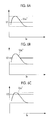
Fig. 6 is a diagram illustrating a DC voltage command that is selected by a selection unit. - A motor drive device according to an embodiment of the invention, an air conditioner, and a method of controlling a converter will be described below with reference to the drawings.
-
Fig. 1 is a view showing the schematic configuration of a motor drive device according to an embodiment of the invention. The motor drive device 1 is a motor drive device that drives a compressor motor of an air conditioner, particularly, an outdoor unit. As shown inFig. 1 , the motor drive device 1 includes a converter 2 and aninverter 3 as main components. The converter 2 converts AC power input from an AC power supply 4 into DC power and outputs the DC power, and theinverter 3 converts the DC power output from the converter 2 into three-phase AC power and outputs the three-phase AC power to acompressor motor 16. - The converter 2 includes a rectifier circuit 5, a smoothing capacitor (smoothing means) 12, two
booster circuits smoothing capacitor 12 is connected in parallel with the rectifier circuit 5 on the DC-output side of the rectifier circuit 5, the twobooster circuits smoothing capacitor 12, and theconverter control unit 15 controls thebooster circuits booster circuits Fig. 1 , but only one booster circuit may be provided. - The
booster circuit 10a includes an inductor (inductive element) 6a that is provided in series on a positive electrode bus Lp connecting the rectifier circuit 5 to thesmoothing capacitor 12, adiode 7a that is connected in series to a current-output side of theinductor 6a, and aswitching element 8a of which one end is connected between theinductor 6a and thediode 7a and which is connected in parallel with the rectifier circuit 5. - Likewise, the
booster circuit 10b includes aninductor 6b that is provided in series on the positive electrode bus Lp connecting the rectifier circuit 5 to thesmoothing capacitor 12, adiode 7b that is connected in series to a current-output side of theinductor 6b, and aswitching element 8b of which one end is connected between theinductor 6b and thediode 7b and which is connected in parallel with the rectifier circuit 5. - Examples of the
switching elements - The
inverter 3 includes abridge circuit 18 that includes six switching elements and aninverter control unit 19 that controls the opening and closing of the switching elements of thebridge circuit 18. Theinverter control unit 19 generates a gate drive signal Spwm for each switching element on the basis of a required rotational speed command input from, for example, a host device (not shown), and gives the gate drive signal to thebridge circuit 18. Examples of a specific method of inverter control include vector control, sensorless vector control, V/F control, overmodulation control, and one-pulse control. - The motor drive device 1 is provided with a
current measurement unit 11 that measures a power supply input current Ia and avoltage measurement unit 13 that measures a DC voltage Vdc. A measurement signal, which is output from thecurrent measurement unit 11, is output to theconverter control unit 15. A measurement signal, which is output from thevoltage measurement unit 13, is output to theconverter control unit 15 and theinverter control unit 19. - Each of the
converter control unit 15 and theinverter control unit 19 is, for example, an MPU (Micro Processing Unit), and includes a recording medium which can be read by a computer and in which a program for performing each processing to be described below is recorded. A CPU reads the program, which is recorded in the recording medium, in a main storage unit such as a RAM, and executes the program, so that each processing is performed. Examples of the recording medium, which can be read by a computer, include a magnetic disc, a magnetooptical disc, and a semiconductor memory. - The
converter control unit 15 and theinverter control unit 19 may be embodied as one MPU, and may be embodied as individual MPUs. When theconverter control unit 15 and theinverter control unit 19 are embodied as individual MPUs, theconverter control unit 15 and theinverter control unit 19 are adapted so that data communication can be performed by both of the MPUs. -
Fig. 2 is a functional block diagram of theconverter control unit 15. As shown inFig. 2 , theconverter control unit 15 includes acommand setting unit 20 and aswitching control unit 30. Thecommand setting unit 20 sets a DC voltage command Vdc*. The switchingcontrol unit 30 controls the opening and closing of theswitching elements booster circuits command setting unit 20. - More specifically, the
command setting unit 20 includes a firstcommand determination unit 21, a secondcommand determination unit 22, and aselection unit 23. - The first
command determination unit 21 determines a first DC voltage command Vi*, which corresponds to the power supply input current Ia, by using first information in which the power supply input current Ia is associated with the first DC voltage command Vi* used to suppress harmonics included in the power supply input current Ia within a predetermined regulation value.Fig. 3 shows an example of the first information. InFig. 3 , the horizontal axis represents the power supply input current Ia and the vertical axis represents the first DC voltage command Vi*. As shown inFig. 3 , a property of the first DC voltage command Vi* relative to the power supply input current Ia takes a peak in an intermediate region that corresponds to a range of 20% to 50% of the maximum current value Imax of the power supply input current Ia, and the first DC voltage command Vi* has a property in which the first DC voltage command Vi* is gradually decreased with an increase or a decrease in the power supply input current Ia at a power supply input current Ip where the peak is taken. - For example, in an air conditioner of a 6 horsepower class, for example, the maximum current value is set to 25 A and the peak of the first DC voltage command Vi* is set in the range of 7 A to 10 A. For example, the first DC voltage command Vi* may be set so that a sine wave is formed.
- The first information may be given in the form of a function that uses the power supply input current Ia as a parameter, and may be provided in the form of a table shown in
Fig. 3 . - The second
command determination unit 22 determines a second DC voltage command Vω*, which corresponds to the rotational speed ω of thecompressor motor 16, by using second information in which the rotational speed ω of thecompressor motor 16 is associated with the second DC voltage command Vω*. Here, rotational speed ω, which is used to control thecompressor motor 16 through theinverter 3, may be used as the rotational speed ω of thecompressor motor 16. Specifically, rotational speed ω, which is supplied to theconverter control unit 15 from theinverter control unit 19, is used as the rotational speed ω of thecompressor motor 16. -
Fig. 4 shows an example of the second information. InFig. 4 , a horizontal axis represents the rotational speed ω of thecompressor motor 16 and a vertical axis represents the second DC voltage command Vω*. It is preferable that a property of the second DC voltage command Vω* relative to the rotational speed ω of thecompressor motor 16 is set to a value larger than a counter electromotive voltage property Vm of thecompressor motor 16 and is set to show the same inclination as a counter electromotive voltage Vm of thecompressor motor 16 as shown inFig. 4 . - For example, when the DC voltage Vdc is set to be smaller than the value of a DC voltage Vdc that is required to achieve a required rotational speed of the
compressor motor 16, field-weakening control is required in a high-speed rotation region. For this reason, a loss is increased. Conversely, when the DC voltage Vdc is set to a value larger than a value that is required by thecompressor motor 16, switching is excessive. For this reason, a loss is increased. Accordingly, it is possible to suppress a switching loss to the lowest level by setting the minimum second DC voltage command, which is required to obtain a required rotational speed of thecompressor motor 16, according to the rotational speed ω of thecompressor motor 16. - The second information may be given in the form of a function that uses the rotational speed ω of the
compressor motor 16 as a parameter, and may be provided in the form of a table shown inFig. 4 . - In the first information and the second information, the upper limits of the first DC voltage command Vi* and the second DC voltage command Vω* are set to be equal to or lower than the withstand voltage of the electronic component (for example, the smoothing capacitor 12) mounted on the motor drive device 1 and the lower limits thereof are set to be equal to or higher than the peak value of the power supply input current Ia supplied from the AC power supply 4.
- The
selection unit 23 selects a larger one of the first DC voltage command Vi* and the second DC voltage command Vω*, and gives the larger one to the switchingcontrol unit 30 as a current-voltage command Vdc*. - The switching
control unit 30 controls theswitching elements booster circuits control unit 30 makes the measured value of the DC voltage Vdc correspond to the DC voltage command Vdc* by performing PAM control. Since a well-known method can be employed for the control of switching that is performed by the switchingcontrol unit 30, the detailed description thereof will be omitted here. - Next, the operation of the converter 2 having the above-mentioned configuration will be described with reference to
Fig. 5 . - First, the measured value of the power supply input current Ia is input to the
converter control unit 15 from thecurrent measurement unit 11, the rotational speed ω of thecompressor motor 16 is input to theconverter control unit 15 from theinverter control unit 19, and the measured value of the DC voltage Vdc is input to theconverter control unit 15 from the voltage measurement unit 13 (Step SA1 ofFig. 5 ). - The first
command determination unit 21 of theconverter control unit 15 determines the first DC voltage command Vi*, which corresponds to the input power supply input current Ia, by using the first information (seeFig. 3 ) (Step SA2). Likewise, the secondcommand determination unit 22 determines the second DC voltage command Vω*, which corresponds to the input rotational speed ω of thecompressor motor 16, from the second information (seeFig. 4 ) (Step SA3). Subsequently, theselection unit 23 selects the one, which has a larger value, between the first DC voltage command Vi* and the second DC voltage command Vω* as the DC voltage command Vdc* (Step SA4). - For example, when the rotational speed ω of the
compressor motor 16 is in a low-rotational speed region, the second DC voltage command Vω* has a relatively small value (Vω*=V1) as shown inFig. 6A . Accordingly, the first DC voltage command Vi* is selected in a wide range of the power supply input current Ia. When the rotational speed ω of thecompressor motor 16 is in a middle-rotational speed range, the value of the second DC voltage command Vω* is larger than that in the low-rotational speed region (Vω*=V2>V1) as shown inFig. 6B . Accordingly, a range in which the second DC voltage command Vω* is selected is widened. Further, in a high-rotational speed range where the value of the second DC voltage command Vω* is increased (Vω*=V3>V2), the second DC voltage command Vω* is selected in a wide range of the power supply input current Ia as shown inFig. 6C . - The current-voltage command Vdc* selected by the
selection unit 23 is given to the switchingcontrol unit 30, and the opening and closing of theswitching elements booster circuits - As described above, according to the motor drive device of this embodiment, the air conditioner, and a method of controlling the converter, the harmonics included in the power supply input current become equal to or smaller than a predetermined regulation value and the value of the minimum DC voltage Vdc, which allows the rotational speed ω required in the
compressor motor 16 to be achieved, can be set as the DC voltage command Vdc*. Accordingly, since the frequency of the opening and closing of theswitching elements booster circuits -
- 1:
- motor drive device
- 2:
- converter
- 3:
- inverter
- 4:
- AC power supply
- 5:
- rectifier circuit
- 8a, 8b:
- switching element
- 10a, 10b:
- booster circuit
- 11:
- current measurement unit
- 12:
- smoothing capacitor
- 13:
- voltage measurement unit
- 15:
- converter control unit
- 16:
- compressor motor
- 19:
- inverter control unit
- 20:
- command setting unit
- 21:
- first command determination unit
- 22:
- second command determination unit
- 23:
- selection unit
- 30:
- switching control unit
Claims (6)
- A motor drive device that drives a compressor motor mounted on an air conditioner, the motor drive device comprising:a converter that converts AC power input from an AC power supply into DC power and outputs the DC power; andan inverter that converts the DC power output from the converter into AC power and supplies the AC power to a compressor motor,wherein the converter includes rectification means for converting the AC power input from an AC power supply into DC power, smoothing means that is connected in parallel with the rectification means on a DC-output side of the rectification means, at least one voltage-increasing means that is provided between the rectification means and the smoothing means and increases voltage by performing the opening and closing of switching elements, and converter control means,the converter control means includes command setting means for setting a DC voltage command, and switching control means for controlling the opening and closing of the switching elements, which are included in the voltage-increasing means, on the basis of the DC voltage command set by the command setting means, andthe command setting means includes first command determination means for determining a first DC voltage command, which corresponds to a power supply input current, by using first information in which the power supply input current is associated with the first DC voltage command used to suppress harmonics included in the power supply input current within a predetermined regulation value, second command determination means for determining a second DC voltage command, which corresponds to a rotational speed of the compressor motor, by using second information in which the rotational speed of the compressor motor is associated with the second DC voltage command, and selection means for selecting a larger one of the first DC voltage command and the second DC voltage command and giving the selected one to the switching control means as the DC voltage command.
- The motor drive device according to claim 1,
wherein a property of the first DC voltage command relative to the power supply input current takes a peak in an intermediate region of the power supply input current, and is a property in which the first DC voltage command is gradually decreased at the peak. - The motor drive device according to claim 1 or 2,
wherein a property of the second DC voltage command relative to the rotational speed of the compressor motor is set to a value larger than a counter electromotive voltage property of the compressor motor and is set to show the same inclination as a counter electromotive voltage of the compressor motor. - The motor drive device according to any one of claims 1 to 3,
wherein an upper limit of the current-voltage command is set to be equal to or lower than a withstand voltage of an electronic component mounted on the motor drive device and a lower limit of the current-voltage command is set to be equal to or higher than a peak value of the power supply input current supplied from the AC power supply. - An air conditioner comprising:the motor drive device according to any one of claims 1 to 4.
- A method of controlling a converter applied to a motor drive device, the motor drive device including a converter and an inverter, the converter including rectification means for converting AC power input from an AC power supply into DC power, smoothing means that is connected in parallel with the rectification means on a DC-output side of the rectification means, and at least one voltage-increasing means that is provided between the rectification means and the smoothing means, and the inverter converting the DC power output from the converter into AC power and supplying the AC power to a compressor motor, the method comprising:a first command determination step of determining a first DC voltage command, which corresponds to a power supply input current, by using first information in which the power supply input current is associated with the first DC voltage command used to suppress harmonics included in the power supply input current within a predetermined regulation value,a second command determination step of determining a second DC voltage command, which corresponds to a rotational speed of the compressor motor, by using second information in which the rotational speed of the compressor motor is associated with the second DC voltage command,a selection step of selecting a larger one of the first DC voltage command and the second DC voltage command as a DC voltage command, anda switching control step of controlling the opening and closing of switching elements, which are included in the voltage-increasing means, on the basis of the selected DC voltage command.
Applications Claiming Priority (2)
| Application Number | Priority Date | Filing Date | Title |
|---|---|---|---|
| JP2012267233 | 2012-12-06 | ||
| PCT/JP2013/072164 WO2014087706A1 (en) | 2012-12-06 | 2013-08-20 | Motor drive device, air conditioner, and converter control method |
Publications (2)
| Publication Number | Publication Date |
|---|---|
| EP2894783A1 true EP2894783A1 (en) | 2015-07-15 |
| EP2894783A4 EP2894783A4 (en) | 2017-05-03 |
Family
ID=50883137
Family Applications (1)
| Application Number | Title | Priority Date | Filing Date |
|---|---|---|---|
| EP13860449.1A Withdrawn EP2894783A4 (en) | 2012-12-06 | 2013-08-20 | Motor drive device, air conditioner, and converter control method |
Country Status (3)
| Country | Link |
|---|---|
| EP (1) | EP2894783A4 (en) |
| JP (1) | JP5925337B2 (en) |
| WO (1) | WO2014087706A1 (en) |
Cited By (1)
| Publication number | Priority date | Publication date | Assignee | Title |
|---|---|---|---|---|
| EP3399643A4 (en) * | 2015-12-28 | 2018-11-07 | Daikin Industries, Ltd. | Device for controlling power conversion apparatus |
Families Citing this family (2)
| Publication number | Priority date | Publication date | Assignee | Title |
|---|---|---|---|---|
| JP2019054609A (en) * | 2017-09-14 | 2019-04-04 | パナソニックIpマネジメント株式会社 | Motor drive device |
| CN117674597B (en) * | 2022-08-31 | 2024-09-17 | 广东美的制冷设备有限公司 | Control method of power supply circuit, controller, air conditioner and readable storage medium |
Family Cites Families (6)
| Publication number | Priority date | Publication date | Assignee | Title |
|---|---|---|---|---|
| JP3424461B2 (en) | 1996-10-18 | 2003-07-07 | 株式会社日立製作所 | PWM / PAM control type motor drive device and air conditioner using the same |
| US6075328A (en) * | 1996-10-18 | 2000-06-13 | Hitachi, Ltd. | PWM/PAM control mode switching type motor control apparatus, and motor drive and air-conditioner using the same |
| JP2006340448A (en) * | 2005-05-31 | 2006-12-14 | Toshiba Corp | Electric motor control device |
| JP2009207307A (en) * | 2008-02-28 | 2009-09-10 | Hitachi Appliances Inc | Motor drive device |
| US8643316B2 (en) * | 2008-09-05 | 2014-02-04 | Mitsubishi Electric Corporation | Power conversion device |
| JP4487008B2 (en) * | 2008-12-03 | 2010-06-23 | シャープ株式会社 | Power supply |
-
2013
- 2013-08-20 EP EP13860449.1A patent/EP2894783A4/en not_active Withdrawn
- 2013-08-20 JP JP2014550948A patent/JP5925337B2/en active Active
- 2013-08-20 WO PCT/JP2013/072164 patent/WO2014087706A1/en not_active Ceased
Cited By (1)
| Publication number | Priority date | Publication date | Assignee | Title |
|---|---|---|---|---|
| EP3399643A4 (en) * | 2015-12-28 | 2018-11-07 | Daikin Industries, Ltd. | Device for controlling power conversion apparatus |
Also Published As
| Publication number | Publication date |
|---|---|
| JPWO2014087706A1 (en) | 2017-01-05 |
| EP2894783A4 (en) | 2017-05-03 |
| WO2014087706A1 (en) | 2014-06-12 |
| JP5925337B2 (en) | 2016-05-25 |
Similar Documents
| Publication | Publication Date | Title |
|---|---|---|
| EP2750279B1 (en) | Converter circuit and motor drive control apparatus, air-conditioner, refrigerator, and induction heating cooker provided with the circuit | |
| KR101297453B1 (en) | Motor control device and air conditioner | |
| CN104885351B (en) | Converter apparatus and air regulator | |
| KR101272356B1 (en) | Motor control device, air-conditioner | |
| CN102005949A (en) | Converter device, module for driving motor, refrigerating apparatus, harmonic reducing device | |
| US9450523B2 (en) | Motor drive apparatus | |
| JP2008113514A (en) | Power supply circuit and control circuit used therefor | |
| KR20160007845A (en) | BLDC FAN motor drive control system | |
| KR101514391B1 (en) | Vector controller and motor controller using the same, air-conditioner | |
| CN101521483A (en) | motor drive | |
| JP2012044830A (en) | Power conversion equipment | |
| JP2017184397A (en) | Three-phase voltage doubler rectifier circuit, inverter device, air conditioner, control method and program of three-phase voltage doubler rectifier | |
| JP5925337B2 (en) | Motor drive device, air conditioner, and converter device control method | |
| WO2015104820A1 (en) | Power conversion device | |
| KR101326494B1 (en) | Method for reducing conduction loss of IGBT for converting voltage modulation of inverter | |
| JP3490600B2 (en) | Pulse width modulation method for power converter | |
| JP2018007502A (en) | Power conversion device, air conditioner and control method for power conversion device | |
| JP5272484B2 (en) | Three-phase brushless DC motor controller | |
| WO2022149214A1 (en) | Power conversion device, air conditioner, and refrigeration cycle application device | |
| JPWO2018034007A1 (en) | Power converter | |
| EP3041121B1 (en) | Converter control device and control method, and air conditioner | |
| JP2013135516A (en) | Electric power conversion system and air conditioner | |
| JP2006042579A (en) | Switching control method, rectifier, and drive system | |
| KR20180137994A (en) | Power transforming apparatus and air conditioner including the same | |
| JP2025140718A (en) | Power control device, power control method, and air conditioner |
Legal Events
| Date | Code | Title | Description |
|---|---|---|---|
| PUAI | Public reference made under article 153(3) epc to a published international application that has entered the european phase |
Free format text: ORIGINAL CODE: 0009012 |
|
| 17P | Request for examination filed |
Effective date: 20150410 |
|
| AK | Designated contracting states |
Kind code of ref document: A1 Designated state(s): AL AT BE BG CH CY CZ DE DK EE ES FI FR GB GR HR HU IE IS IT LI LT LU LV MC MK MT NL NO PL PT RO RS SE SI SK SM TR |
|
| AX | Request for extension of the european patent |
Extension state: BA ME |
|
| DAX | Request for extension of the european patent (deleted) | ||
| RA4 | Supplementary search report drawn up and despatched (corrected) |
Effective date: 20170403 |
|
| RIC1 | Information provided on ipc code assigned before grant |
Ipc: H02M 7/48 20070101ALI20170328BHEP Ipc: H02M 7/12 20060101ALI20170328BHEP Ipc: H02M 3/155 20060101ALI20170328BHEP Ipc: H02P 27/06 20060101AFI20170328BHEP |
|
| RAP1 | Party data changed (applicant data changed or rights of an application transferred) |
Owner name: MITSUBISHI HEAVY INDUSTRIES THERMAL SYSTEMS, LTD. |
|
| STAA | Information on the status of an ep patent application or granted ep patent |
Free format text: STATUS: EXAMINATION IS IN PROGRESS |
|
| 17Q | First examination report despatched |
Effective date: 20200402 |
|
| STAA | Information on the status of an ep patent application or granted ep patent |
Free format text: STATUS: THE APPLICATION HAS BEEN WITHDRAWN |
|
| 18W | Application withdrawn |
Effective date: 20200701 |