EP2894719A1 - Vorrichtung zur Ableitung eines Kurzschlussstroms - Google Patents
Vorrichtung zur Ableitung eines Kurzschlussstroms Download PDFInfo
- Publication number
- EP2894719A1 EP2894719A1 EP15150736.5A EP15150736A EP2894719A1 EP 2894719 A1 EP2894719 A1 EP 2894719A1 EP 15150736 A EP15150736 A EP 15150736A EP 2894719 A1 EP2894719 A1 EP 2894719A1
- Authority
- EP
- European Patent Office
- Prior art keywords
- profile body
- clamp
- grounding
- line
- fastening means
- Prior art date
- Legal status (The legal status is an assumption and is not a legal conclusion. Google has not performed a legal analysis and makes no representation as to the accuracy of the status listed.)
- Granted
Links
Images
Classifications
-
- H—ELECTRICITY
- H01—ELECTRIC ELEMENTS
- H01R—ELECTRICALLY-CONDUCTIVE CONNECTIONS; STRUCTURAL ASSOCIATIONS OF A PLURALITY OF MUTUALLY-INSULATED ELECTRICAL CONNECTING ELEMENTS; COUPLING DEVICES; CURRENT COLLECTORS
- H01R4/00—Electrically-conductive connections between two or more conductive members in direct contact, i.e. touching one another; Means for effecting or maintaining such contact; Electrically-conductive connections having two or more spaced connecting locations for conductors and using contact members penetrating insulation
- H01R4/58—Electrically-conductive connections between two or more conductive members in direct contact, i.e. touching one another; Means for effecting or maintaining such contact; Electrically-conductive connections having two or more spaced connecting locations for conductors and using contact members penetrating insulation characterised by the form or material of the contacting members
- H01R4/64—Connections between or with conductive parts having primarily a non-electric function, e.g. frame, casing, rail
- H01R4/643—Connections between or with conductive parts having primarily a non-electric function, e.g. frame, casing, rail for rigid cylindrical bodies
-
- B—PERFORMING OPERATIONS; TRANSPORTING
- B61—RAILWAYS
- B61F—RAIL VEHICLE SUSPENSIONS, e.g. UNDERFRAMES, BOGIES OR ARRANGEMENTS OF WHEEL AXLES; RAIL VEHICLES FOR USE ON TRACKS OF DIFFERENT WIDTH; PREVENTING DERAILING OF RAIL VEHICLES; WHEEL GUARDS, OBSTRUCTION REMOVERS OR THE LIKE FOR RAIL VEHICLES
- B61F99/00—Subject matter not provided for in other groups of this subclass
Definitions
- the invention relates to a device which is suitable for guiding electrical lines or as a holding device for persons and a rail vehicle having such a device.
- electrical cables such as cables or cables
- Rail vehicles In or on profiled bodies, such as, for example, railway vehicles.
- Metal pipes especially laid in aluminum pipes.
- a grounding is also known in the field of hose technology.
- DE3543233 discloses a contact part for hoses with metal insert, consisting of a base ring with a discharge device made of electrically conductive material, which can be electrically connected by a dimensioned in the diameter of the metal insert of the hose cutting lip with the metal insert of the hose.
- the grounding can be done via a grounding clamp, which is connected to the base ring via an externally applied drainage lug.
- the object of the invention is to provide a solution to these problems.
- the device according to the invention can be used in particular for the guidance of electrical lines, in particular cables, and in particular in rail vehicles.
- the profile body may be referred to as a guide body, mounting body or holding body.
- the device for guiding electrical lines in or on the substructure of a rail vehicle can be used particularly advantageously.
- a particularly preferred application is the cable routing of the train busbar.
- the profile body can be attached to a substructure, in particular to a subframe, a rail vehicle (especially a car body) or fastened there. The attachment there can be done with the mentioned fastener.
- the device may also be used in general for cable guides, with other examples being cable guides in buildings, airplanes, ships or other vehicles.
- the device can be used as a holding device for persons, wherein the profile body is used for holding or by persons.
- the holding device thus has a mentioned earthing clamp, which serves to dissipate a current and a fastening means with which the holding device can be attached to an object or substrate.
- a mentioned earthing clamp which serves to dissipate a current and a fastening means with which the holding device can be attached to an object or substrate.
- Specific examples are railings, handrails, for example, at railway facilities, which are covered with overhead lines, and handrails in rail vehicles and other vehicles, especially public transport.
- a grounding clamp By using a grounding clamp the disadvantages of a welded grounding described above are avoided. Under a clamp an object is understood, which engages around the electrically conductive profile body.
- the clamp on a clamping device by means of which the clamp can be pressed against the surface of the profile body, so that a positive connection and preferably also positive connection can be produced.
- said earthing clamp and the fastening means for fastening the profile body to a load-bearing object or ground are separate parts.
- the fastener is therefore not needed to ground the profile body.
- the grounding does not have to be ensured via the fastening means.
- no electrical connection must be ensured via the fastening means.
- Changes in the attachment such as in the overhaul or maintenance of a rail vehicle, thus can not unintentionally lead to the loss of grounding contact.
- the fastening means can be screwed to a substrate, wherein care must not be taken that a sufficient electrical line for the purpose of grounding is ensured by the screw.
- the earthing clamp does not serve to fasten the elongated profile body.
- the mentioned profile body is an elongated body.
- the profile body as a conductive material on metal, preferably predominantly metal, or consists of metal.
- the profile body is made of steel or aluminum.
- a profile body made of a first metal can at least at the Be coated outside with another conductive metal.
- An example of this is a galvanized steel.
- the shape of the profile body is not limited.
- the profile body is rigid.
- the cross-sectional shape of the profile body is not limited
- the profile body may be solid or hollow inside.
- a hollow profile is preferably such that a flow can flow from the inside to the outside.
- the inside and the outside in other words the surfaces on the inside and on the outside, are electrically conductive.
- Examples of a solid profile body are a rod, a rod, a T-profile or a rail. These profiles can be used advantageously for the attachment of electrical cables.
- electrical lines can be arranged within a rail.
- An example of this is a C-shaped rail.
- Another example is a roundish rail, for example in cross-section in the form of a circle segment.
- rods or rails are also suitable as a holding device for persons, for example as railings.
- the profile body is a hollow profile body, in particular a tube or an angular hollow profile. Particularly preferred is a steel or aluminum tube.
- a hollow profile body one or more electrical lines, in particular cables, can be guided. The electrical lines are, as with other forms of the profile body, preferably provided with an insulation.
- the mentioned earthing clamp is preferably made of metal, in particular of stainless steel.
- a current from the profile body to the earthing clamp is transferable, ie transferable from the outside of the profile body on the clamp.
- the earthing clamp is in electrical contact with the outside of the profile body.
- the outside of the profile body is conductive for electrical power.
- the device includes a grounding line coupled to the grounding clamp, which may mean a direct or indirect conductive connection to the grounding clamp, such that a current may drain from the grounding clamp via the grounding line.
- the grounding line can be clamped, screwed, soldered or welded to the clamp.
- the grounding clamp and the grounding lead may be connected via a cable lug which is clamped to the grounding clamp.
- grounding line is copper.
- the grounding line is flexible.
- the cross sections of the grounding line and the grounding clamp are adjusted to the desired current conductivity for deriving a short-circuit current.
- the cross-sectional area of the grounding clamp is preferably at least 50 mm 2, more preferably at least 60 mm 2, even more preferably at least 100 mm 2. The meaning and definition of the cross-sectional area is explained with reference to the embodiments.
- the cross section of the grounding line is preferably at least 10 mm 2 , more preferably at least 16 mm 2 , even more preferably at least 25 mm 2 or at least 35 mm 2 and most preferably at least 50 mm 2 .
- the ratio of the cross-sectional area of the grounding line to the cross-sectional area of the grounding clip corresponds to the ratio of the conductivity of the material of the grounding line to the conductivity of the material of the grounding clip.
- the above-mentioned cross sections of the earthing line can be varied with these ratios.
- the aforementioned cross sections of the earthing clamps can be varied with the mentioned ratios. Maximum short-circuit temperatures and short-circuit currents achievable with the selected cross-sectional areas are mentioned in the example section.
- At least one layer of a corrosion-protecting, conductive material is arranged between the grounding clamp and the profile body.
- This material protects in particular the profile body from corrosion, For example, if the profile body is of a less noble metal than the grounding clamp.
- the layer is made of a conductive grease, also referred to as contact grease.
- An advantage of such a fat is that it does not have to be renewed for at least 30 years.
- the surface of the profile body is cleaned before application of the fat, for example with an organic solvent, in particular alcohol.
- the layer is made of a metal that is nobler than the metal from which the profile body or at least the surface of the profile body is made.
- the layer is made of tin, copper, zinc, or a combination thereof.
- a specific example is a copper layer that has a tin coating.
- the profile body may be coated with such a metal layer, in particular a tin, copper or zinc layer, at least where the grounding clamp is attached to the profile body.
- the variants described can be combined: One or more metal layers can be combined with a layer of grease.
- the fastening means is a mounting clamp, for example a pipe clamp, when the profile body is a pipe.
- the fastening means in particular a fastening clamp, can be electrically conductive. It is possible in this case that a short-circuit current is also dissipated via the fastening means. However, this derivation of the short-circuit current via fastening means is redundant, since the earthing clamp is already sufficiently dimensioned for the purpose of dissipating the current.
- the attachment means has a higher resistance than the grounding clamp to guide the flow of current substantially across the grounding clamp. Between a conductive fastening means and the profile body, an insulating means may be provided. However, this is not essential.
- the invention relates to a rail vehicle, in particular a tram, a locomotive, a railcar, a wagon or a train combination, comprising a device according to the invention described above.
- the device is arranged on the substructure of the rail vehicle, in particular on a subframe.
- the device is attached to the substructure of the rail vehicle, in particular to a subframe.
- a flexible grounding line is used, for example a wire mesh or wire rope.
- at least one electrical line of the rail vehicle is preferably arranged, in particular a train busbar.
- the device according to the invention is used as a holding device for persons, then it is preferably arranged in the interior of a rail vehicle, for example in the form of a holding rod.
- the invention relates to the use of the device described above for deriving a short-circuit current.
- a short-circuit current is derived from the profile body via the earthing clamp and preferably via a grounding line which continues to be present.
- the device can be used as a grounded device for guiding lines or as a grounded holding device for persons, as previously discussed.
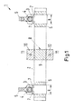
- Fig. 1 shows a device according to the invention with an electrically conductive profile body 2, which in this case a tube (see Fig. 2 ).
- an electrically conductive profile body 2 which in this case a tube (see Fig. 2 ).
- the earthing clamps 3 are each clamped with clamping screws 4 to the tube 2, wherein by means of the clamping screws 4 and a respective cable lug 5 is attached to the clamp.
- a grounding line is attached, which in Fig. 2 is shown in more detail.
- the layer 6 may, for example, a layer of be conductive grease or a layer of a nobler metal, in particular tin or zinc, with the tube 2 is coated. It suffices a coating in the area where the clamps 3 are clamped.
- a fastener 8 in the form of a mounting clamp with a part encompassing the tube 2 and two laterally protruding tabs 10, each having a bore 11.
- the device 1 can be attached, for example, to the substructure of a rail vehicle, as in Fig. 3 shown.
- illustrated earthing clamps 3 and the fastener 8 are only exemplary. There may be more than the illustrated fastener 8 and more than the grounding clamps 3 shown. Further, the tube 2 may be made longer than in Fig. 1 shown.
- the device may further comprise a plurality of profile body 2, which adjoin one another.
- the width of the earthing clamps 3 is indicated by the arrow B. Depending on the short-circuit current to be dissipated, the width B of the earthing clamp can be chosen differently.
- the cross section of the earthing clamp 3 results from the width B times the in Fig. 2 shown thickness D of the grounding clamp. 3
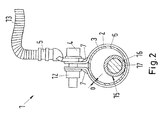
- Fig. 2 shows a cross section through the device 1, more precisely a cross section through the grounding point 3 and the tube 2. It can be seen how the clamp 3 is clamped by means of the fastening screw 4 and the nut 12 to the tube 2. Furthermore, stiffening webs 7 are shown. At the fixed with the screw 4 on the clamp 3 lug 5 is a grounding line 13, preferably made of copper braid attached. Between the tube 2 and the clamp 3, the layer 6 is arranged from a corrosion-protective, conductive material.
- an electrical line 15 is laid, comprising an insulation 16 and a conductive core 17.
- the line 15 is a line of a Switzerlandsammelschiene. In the example only one line is shown and others can be present. If the insulation 16 is damaged, short-circuiting, that is to say the current flow from the conductive core 17 to the pipe 2, can occur. The short-circuit current is passed over the surface of the tube 2 and the conductive intermediate layer 6 on the grounding clamp 3 and flows through the cable lug 5 and the grounding line 13 from.
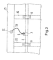
- Fig. 3 shows a view from below of the undercarriage of a rail car.
- Fig. 3 shows the attachment of the device 1 to the substructure of a rail vehicle in a sectional view.
- the previously explained tube 2 is fastened by means of two earthing clamps 8 to cross members 20 of a lower frame.
- the attachment is done here by screwing.
- the grounding clamp 3, already based Fig. 1 has been explained, does not serve the attachment, so it is not connected to any part of the substructure or subframe and only clamped to the tube 2.
- the grounding line 13 is guided to the longitudinal member 21 of the undercarriage and secured thereto.
- a schematically illustrated grounding tab 22 is fastened, for example welded, to the longitudinal member 21.
- the grounding line 13 is attached, for example by means of a screw or welding.
- a section of a base frame is shown.
- a plurality of pipe sections 2 may be arranged on the underframe, which are preferably arranged in each case in alignment with one another axially, so that a device 1 according to the invention may be composed of several pipe sections 2.
- Per pipe section preferably two grounding clamps 3 are used, with very short pipes depending on the technical requirement, if necessary, a grounding clamp is sufficient.
- the fastening clamps 8 are conductive, ie they could also lead to a short circuit on the pipe 2 to the underframe, they have a higher electrical resistance than the earthing clamps, since the short-circuit current is to be derived predominantly via the earthing clamps 3. Insulation may be provided between the cross member 20 and the mounting clips 8 to prevent current flow, but this is not necessary. In particular, insulation is not necessary if the fastening clamps 8 have a higher electrical resistance than the grounding clamp 3.
- a Switzerlandsammelschiene can be arranged in the interior of the tube 2.
- any other electrical line may be disposed in the tube 2, for example an electrical line for a brake.
- exemplary cross sections for a ground clamp and exemplary cross sections for a ground line 13 are shown in Table 1.
- the cross section is calculated from the in Fig. 1 shown width B, a clamp 3 multiplied by the in Fig. 2 shown thickness D.
- the maximum short circuit currents and maximum short circuit temperatures shown in Table 1 are possible.
- the cross section of the ground wire 13 can be chosen differently. For a 60 mm 2 clamp cross section, the optimum cross section of the copper cable is 16 mm 2, and for a 100 mm 2 clamp cross section, the maximum cross section of the copper cable is 50 mm 2 .
Landscapes
- Engineering & Computer Science (AREA)
- Mechanical Engineering (AREA)
- Elimination Of Static Electricity (AREA)
- Train Traffic Observation, Control, And Security (AREA)
Abstract
Description
- Die Erfindung betrifft eine Vorrichtung die zur Führung von elektrischen Leitungen oder als Haltevorrichtung für Personen verwendbar ist und ein Schienenfahrzeug, das eine solche Vorrichtung aufweist.
- Zum Schutz vor mechanischen Beschädigungen werden elektrische Leitungen, wie beispielsweise Leitungen mit Isolierung bzw. Kabel, in Schienenfahrzeugen häufig in oder an Profilkörpern, wie z.B. Metallrohren, insbesondere in Aluminiumrohren verlegt.
- Wird die elektrische Leitung dennoch beschädigt, insbesondere eine Isolation, kann ein Strom auf das Rohr oder Schiene übertragen werden und ein unerwünschter Kurzschluss entstehen, was insbesondere bei Hochspannungsleitungen sehr problematisch ist. Zur Sicherheit werden die Rohre oder Schienen, worin oder woran die Leitungen geführt sind, geerdet.
- Eine Erdung ist auch aus dem Bereich der Schlauchtechnik bekannt.
DE3543233 offenbart ein Kontaktteil für Schläuche mit Metalleinlage, bestehend aus einem Grundring mit einer Ableitungsvorrichtung aus elektrisch leitendem Material, das durch eine im Durchmesser der Metalleinlage des Schlauches bemessene Schneidlippe mit der Metalleinlage des Schlauches elektrisch leitend verbunden werden kann. Die Erdung kann über eine Erdungsschelle erfolgen, die mit dem Grundring über eine außen anliegende Ableitungsfahne verbunden ist. Mit diesem Aufbau wird eine elektrostatische Ableitung ermöglicht, jedoch keine Kurzschlusssicherheit. - Die Erdung stellt im Fall von Aluminiumrohren eine besondere Herausforderung dar, da hier mehrere Faktoren eine einwandfreie Erdung schwierig machen. Die wesentlichen Anforderungen für Erdungsverbindungen auf Schienenfahrzeugen sind folgende:
- Die Kurzschlussstromtragfähigkeit der Verbindung muss dem maximal möglichen Kurzschlussstrom entsprechen.
- Die Erdungsverbindung muss überprüfbar sein.
- Die Anbringung von Erdungsleitungen an Rohren oder Schienen kann durch Anschweißen erfolgen. Elektrische Verbindungen insbesondere zu Aluminiumrohren sind aber so nicht einfach zu realisieren. Anschweißteile für Aluminiumrohre sind teuer und unhandlich.
- Ferner ist eine elektrische und mechanische Anbindung von Erdungsleitungen an hohle Profilkörper mit dünner Wandung mittels Schweißen unvorteilhaft, da durch die eingetragene Energie eine thermische Verformung auftreten kann. Im Inneren des Profilkörpers können Schadstellen entstehen und im Inneren des Profilkörpers verlegte elektrische Leitungen können an diesen Schadstellen während des Betriebes aufgescheuert werden.
- Die Aufgabe der Erfindung ist, eine Lösung für diese Probleme anzugeben.
- Angegeben wird von der Erfindung eine Vorrichtung, aufweisend
- einen elektrisch leitfähigen Profilkörper,
- zumindest eine den Profilkörper außen umgreifende elektrisch leitfähige Erdungsschelle, wobei ein Strom von der Außenseite des Profilkörpers auf die Erdungsschelle übertragbar ist,
- zumindest ein Befestigungsmittel zur Befestigung des Profilkörpers an einem tragfähigen Gegenstand oder Untergrund.
- Die erfindungsgemäße Vorrichtung ist insbesondere verwendbar zur Führung von elektrischen Leitungen, insbesondere Kabel, und insbesondere in Schienenfahrzeugen. In diesem Zusammenhang kann der Profilkörper als Führungskörper, Befestigungskörper oder Haltekörper bezeichnet werden. Besonders vorteilhaft einsetzbar ist die Vorrichtung zur Führung von elektrischen Leitungen im oder am Unterbau eines Schienenfahrzeugs. Eine besonders bevorzugte Anwendung ist die Leitungsverlegung der Zugsammelschiene. Der Profilkörper kann an einem Unterbau, insbesondere an einem Untergestell, eines Schienenfahrzeugs (speziell eines Wagenkastens) befestigt werden oder dort befestigt sein. Die Befestigung dort kann mit dem erwähnten Befestigungsmittel erfolgen.
- Die Vorrichtung kann auch für Kabelführungen allgemein eingesetzt werden, wobei weitere Beispiele Kabelführungen in Gebäuden, Flugzeugen, Schiffen oder anderen Fahrzeugen sind.
- In einer anderen Variante ist die Vorrichtung verwendbar als Haltevorrichtung für Personen, wobei zum Festhalten von oder durch Personen der Profilkörper dient. Die Haltevorrichtung weist somit eine erwähnte Erdungsschelle auf, die zur Ableitung eines Stromes dient und ein Befestigungsmittel, mit dem die Haltevorrichtung an einem Gegenstand oder Untergrund befestigt werden kann. Spezielle Beispiele sind Geländer, Handläufe, beispielsweise an bahnbetrieblichen Einrichtungen, die mit Oberleitungen überspannt sind, und Haltestangen in Schienenfahrzeugen und anderweitigen Fahrzeugen, insbesondere des öffentlichen Nahverkehrs.
- Durch die Verwendung einer Erdungsschelle werden die eingangs beschriebenen Nachteile einer angeschweißten Erdung vermieden. Unter einer Schelle wird ein Gegenstand verstanden, der den elektrisch leitfähigen Profilkörper umgreift. Vorzugsweise weist die Schelle eine Klemmeinrichtung auf, mittels derer die Schelle an die Oberfläche des Profilkörpers gepresst werden kann, sodass eine kraftschlüssige Verbindung und vorzugsweise auch formschlüssige Verbindung herstellbar ist.
- Nach einer weiteren grundlegenden Idee der Erfindung sind die genannte Erdungsschelle und das Befestigungsmittel zur Befestigung des Profilkörpers an einem tragfähigen Gegenstand oder Untergrund voneinander getrennte Teile. Das Befestigungsmittel wird demgemäß nicht zur Erdung des Profilkörpers benötigt. Die Erdung muss nicht über das Befestigungsmittel sichergestellt werden. Somit muss über das Befestigungsmittel keine elektrische Verbindung sichergestellt werden. Änderungen in der Befestigung, beispielsweise bei der Überholung oder Wartung eines Schienenfahrzeugs, können somit nicht ungewollt zum Verlust des Erdungskontaktes führen. Beispielsweise kann das Befestigungsmittel an einem Untergrund angeschraubt werden, wobei nicht darauf geachtet werden muss, dass durch die Schraubverbindung eine ausreichende elektrische Leitung zwecks Erdung sichergestellt ist. Umgekehrt muss erfindungsgemäß die Erdungsschelle nicht der Befestigung des langgestreckten Profilkörpers dienen.
- Der erwähnte Profilkörper ist ein langgestreckter Körper.
- Vorzugsweise weist der Profilkörper als leitfähiges Material Metall auf, vorzugsweise überwiegend Metall, oder besteht aus Metall. Insbesondere ist der Profilkörper aus Stahl oder Aluminium. Ein Profilkörper aus einem ersten Metall kann zumindest an der Außenseite mit einem anderen leitfähigen Metall beschichtet sein. Ein Beispiel hierfür ist ein verzinkter Stahl.
- Die Formgestalt des Profilkörpers, wie z.B. gerade oder gebogen, ist nicht beschränkt.
- Vorzugsweise ist der Profilkörper starr.
- Die Querschnittsform des Profilkörpers, wie z.B. eckig, rund, gewinkelt, ist nicht beschränkt
- Der Profilkörper kann massiv oder im Inneren hohl sein. Ein Hohlprofil ist vorzugsweise so beschaffen, dass ein Strom von der Innenseite zur Außenseite fließen kann. Anders ausgedrückt sind vorzugsweise die Innenseite und die Außenseite, anders ausgedrückt die Oberflächen auf der Innenseite und auf der Außenseite, elektrisch leitfähig.
- Beispiele für einen massiven Profilkörper sind ein Stab, eine Stange, ein T-Profil oder eine Schiene. Diese Profile können vorteilhaft zur Befestigung von elektrischen Leitungen verwendet werden. Beispielsweise können elektrische Leitungen innerhalb einer Schiene angeordnet sein. Ein Beispiel hierfür ist eine C-förmige Schiene. Ein weiteres Beispiel ist eine rundliche Schiene, beispielsweise im Querschnitt in Form eines Kreissegments. Des Weiteren sind Stäbe oder Schienen auch als Haltevorrichtung für Personen, beispielsweise als Geländer, geeignet.
- In einer anderen Variante der Erfindung ist der Profilkörper ein Hohlprofilkörper, insbesondere ein Rohr oder ein eckiges Hohlprofil. Besonders bevorzugt ist ein Stahl-oder Aluminiumrohr. In einem Hohlprofilkörper können eine oder mehrere elektrische Leitungen, insbesondere Kabel, geführt sein. Die elektrischen Leitungen sind, wie auch bei anderen Formen des Profilkörpers, vorzugsweise mit einer Isolierung versehen.
- Die erwähnte Erdungsschelle ist vorzugsweise aus Metall, insbesondere aus Edelstahl. Wie erwähnt ist ein Strom von dem Profilkörper auf die Erdungsschelle übertragbar, d.h. von der Außenseite des Profilkörpers auf die Schelle übertragbar. Die Erdungsschelle steht mit der Außenseite des Profilkörpers in elektrischem Kontakt. Die Außenseite des Profilkörpers ist leitfähig für elektrischen Strom.
- In einer Ausführungsform der Erfindung weist die Vorrichtung eine Erdungsleitung auf, die mit der Erdungsschelle gekoppelt ist, was eine direkte oder indirekte leitfähige Verbindung mit der Erdungsschelle bedeuten kann, sodass ein Strom von der Erdungsschelle über die Erdungsleitung abfließen kann. Beispielsweise kann die Erdungsleitung an die Schelle angeklemmt, angeschraubt, angelötet oder angeschweißt sein. Beispielsweise können die Erdungsschelle und die Erdungsleitung über einen Kabelschuh verbunden sein, der an die Erdungsschelle angeklemmt ist.
- Ein bevorzugtes Material für die Erdungsleitung ist Kupfer. Vorzugsweise ist die Erdungsleitung flexibel.
- Die Querschnitte der Erdungsleitung und der Erdungsschelle werden an die erwünschte Stromleitfähigkeit zur Ableitung eines Kurzschlussstroms angepasst. Die Querschnittsfläche der Erdungsschelle beträgt vorzugsweise mindestens 50 mm2, mehr bevorzugt mindestens 60 mm2, noch mehr bevorzugt mindestens 100 mm2. Die Bedeutung und Definition der Querschnittsfläche ist anhand der Ausführungsbeispiele erläutert.
- Der Querschnitt der Erdungsleitung, insbesondere einer Erdungsleitung aus Kupfer, beträgt vorzugsweise mindestens 10 mm2, mehr bevorzugt mindestens 16 mm2, noch mehr bevorzugt mindestens 25 mm2 oder mindestens 35 mm2 und am meisten bevorzugt mindestens 50 mm2.
- Vorteilhafterweise entspricht das Verhältnis der Querschnittsfläche der Erdungsleitung zur Querschnittsfläche der Erdungsschelle dem Verhältnis von der Leitfähigkeit des Materials der Erdungsleitung zur Leitfähigkeit des Materials der Erdungsschelle. Die zuvor genannten Querschnitte der Erdungsleitung können mit diesen Verhältnissen variiert werden. Ebenfalls können die zuvor genannten Querschnitte der Erdungsschellen mit den genannten Verhältnissen variiert werden. Mit den gewählten Querschnittsflächen erzielbare maximale Kurzschlusstemperaturen und Kurzschlussströme sind im Beispielteil erwähnt.
- In einer Ausführungsform der Erfindung ist zwischen der Erdungsschelle und dem Profilkörper zumindest eine Schicht aus einem vor Korrosion schützenden, leitfähigen Material angeordnet. Dieses Material schützt insbesondere den Profilkörper vor Korrosion, wenn der Profilkörper beispielsweise aus einem unedleren Metall ist als die Erdungsschelle. In einer Variante ist die Schicht aus einem leitfähigen Fett, auch bezeichnet als Kontaktfett. Ein Vorteil eines solchen Fettes ist, dass es mindestens über 30 Jahre nicht erneuert werden muss. Vorteilhafterweise wird die Oberfläche des Profilkörpers vor Aufbringung des Fettes gereinigt, beispielsweise mit einem organischen Lösungsmittel, insbesondere Alkohol. In einer anderen Variante ist die Schicht aus einem Metall, das edler ist als das Metall, aus dem der Profilkörper oder zumindest die Oberfläche des Profilkörpers gefertigt ist. In einer speziellen Variante ist die Schicht aus Zinn, Kupfer, Zink, oder aus einer Kombination davon. Ein spezielles Beispiel ist eine Kupferschicht, die einen Zinnüberzug aufweist. Beispielsweise kann der Profilkörper mit einer solchen Metallschicht, insbesondere einer Zinn-, Kupfer- oder Zinkschicht, zumindest dort beschichtet sein, wo die Erdungsschelle am Profilkörper angebracht wird. Die beschriebenen Varianten können kombiniert werden: Eine oder mehrere Metallschichten können mit einer Fettschicht kombiniert werden.
- In einer Ausführungsform der Erfindung ist das Befestigungsmittel eine Befestigungsschelle, beispielsweise eine Rohrschelle, wenn der Profilkörper ein Rohr ist. Das Befestigungsmittel, insbesondere eine Befestigungsschelle, kann elektrisch leitfähig sein. Es ist in diesem Fall möglich, dass ein Kurzschlussstrom auch über das Befestigungsmittel abgeleitet wird. Allerdings ist diese Ableitung des Kurzschlussstroms über Befestigungsmittel redundant, da die Erdungsschelle zwecks Ableitung des Stroms bereits ausreichend dimensioniert ist. Vorzugsweise weist das Befestigungsmittel einen höheren Widerstand auf als die Erdungsschelle, um den Stromfluss im Wesentlichen über die Erdungsschelle zu führen. Zwischen einem leitfähigen Befestigungsmittel und dem Profilkörper kann ein Isoliermittel vorgesehen sein. Allerdings ist dies nicht unbedingt erforderlich.
- In einem weiteren Aspekt betrifft die Erfindung ein Schienenfahrzeug, insbesondere eine Straßenbahn, eine Lokomotive, einen Triebwagen, einen Wagon oder einen Zugverbund, aufweisend eine vorangehend beschriebene erfindungsgemäße Vorrichtung. In einer speziellen Ausführungsform ist die Vorrichtung am Unterbau des Schienenfahrzeugs, insbesondere an einem Untergestell, angeordnet. Insbesondere ist die Vorrichtung am Unterbau des Schienenfahrzeugs, insbesondere an einem Untergestell, befestigt. Vorteilhafterweise sind die Erdungsschelle und ein leitfähiges Teil des Schienenfahrzeugs, insbesondere ein leitfähiges Teil eines Unterbaus, Untergestells oder eines Wagenkastens miteinander verbunden, beispielsweise über eine bereits beschriebene Erdungsleitung. Vorteilhafterweise wird eine flexible Erdungsleitung verwendet, beispielsweise ein Drahtgeflecht oder Drahtseil. In oder an dem Profilkörper der Vorrichtung ist vorzugsweise zumindest eine elektrische Leitung des Schienenfahrzeugs angeordnet, insbesondere eine Zugsammelschiene.
- Wenn die erfindungsgemäße Vorrichtung als Haltevorrichtung für Personen eingesetzt wird, dann ist sie vorzugsweise im Innenraum eines Schienenfahrzeugs angeordnet, beispielsweise in Form einer Haltestange.
- In einem weiteren Aspekt betrifft die Erfindung die Verwendung der vorangehend beschriebenen Vorrichtung zur Ableitung eines Kurzschlussstroms. Hierbei wird ein Kurzschlussstrom von dem Profilkörper über die Erdungsschelle und vorzugsweise über eine weiterhin vorhandene Erdungsleitung abgeleitet. Die Vorrichtung kann als geerdete Vorrichtung zur Führung von Leitungen oder als geerdete Haltevorrichtung für Personen verwendet werden, worauf bereits zuvor eingegangen wurde.
- Nachfolgend wird die Erfindung anhand von Ausführungsbeispielen beschrieben. Es zeigen:
- Fig. 1
- eine erfindungsgemäße Vorrichtung in seitlicher Ansicht,
- Fig. 2
- eine erfindungsgemäße Vorrichtung im Querschnitt und
- Fig. 3
- die Befestigung einer erfindungsgemäßen Vorrichtung am Unterbau eines Schienenfahrzeugwagens.
-
Fig. 1 zeigt eine erfindungsgemäße Vorrichtung mit einem elektrisch leitfähigen Profilkörper 2, der in diesem Fall ein Rohr (sieheFig. 2 ) ist. An dem Rohr 2 sind zwei Erdungsschellen 3 befestigt. Die Erdungsschellen 3 sind jeweils mit Klemmschrauben 4 an dem Rohr 2 festgeklemmt, wobei mittels der Klemmschrauben 4 auch jeweils ein Kabelschuh 5 an der Schelle befestigt ist. An den Kabelschuhen 5 ist jeweils eine Erdungsleitung befestigt, die inFig. 2 näher dargestellt ist. Zwischen den Erdungsschellen 3 und dem Rohr 2 ist jeweils eine Schicht 6 aus einem vor Korrosion schützenden leitfähigen Material angeordnet. Die Schicht 6 kann beispielsweise eine Schicht aus leitfähigem Fett sein oder eine Schicht aus einem edleren Metall, wie insbesondere Zinn oder Zink, mit der das Rohr 2 beschichtet ist. Es genügt eine Beschichtung in dem Bereich, an dem die Schellen 3 angeklemmt werden. - Ebenfalls in
Fig. 1 gezeigt ist ein Befestigungsmittel 8 in Form einer Befestigungsschelle mit einem das Rohr 2 umgreifenden Teil 9 und zwei seitlich hervorstehenden Laschen 10 mit jeweils einer Bohrung 11. Mittels der Laschen 10 kann die Vorrichtung 1 beispielsweise an dem Unterbau eines Schienenfahrzeugs angebracht werden, wie inFig. 3 gezeigt. - Die in
Fig. 1 dargestellten Erdungsschellen 3 und das Befestigungsmittel 8 sind nur beispielhaft. Es können noch mehr als das gezeigte Befestigungsmittel 8 und noch mehr als die gezeigten Erdungsschellen 3 vorhanden sein. Ferner kann das Rohr 2 länger ausgeführt sein als inFig. 1 gezeigt. Die Vorrichtung kann ferner mehrere Profilkörper 2 aufweisen, die aneinander anschließen. - Die Breite der Erdungsschellen 3 ist mit dem Pfeil B bezeichnet. Je nach abzuleitendem Kurzschlussstrom kann die Breite B der Erdungsschelle unterschiedlich gewählt werden. Der Querschnitt der Erdungsschelle 3 ergibt sich aus der Breite B mal der in
Fig. 2 gezeigten Dicke D der Erdungsschelle 3. -
Fig. 2 zeigt einen Querschnitt durch die Vorrichtung 1, genauer einen Querschnitt durch die Erdungsstelle 3 und das Rohr 2. Zu sehen ist, wie die Schelle 3 mittels der Befestigungsschraube 4 und der Mutter 12 an das Rohr 2 geklemmt ist. Ferner sind Versteifungsstege 7 dargestellt. An dem mit der Schraube 4 an der Schelle 3 befestigten Kabelschuh 5 ist eine Erdungsleitung 13, vorzugsweise aus Kupfergeflecht, angebracht. Zwischen dem Rohr 2 und der Schelle 3 ist die Schicht 6 aus einem vor Korrosion schützenden, leitfähigen Material angeordnet. - Im Innern des Rohres 2 ist eine elektrische Leitung 15 verlegt, aufweisend eine Isolierung 16 und einen leitfähigen Kern 17. Beispielsweise ist die Leitung 15 eine Leitung einer Zugsammelschiene. Im Beispiel ist nur eine Leitung gezeigt und weitere können vorhanden sein. Bei Beschädigung der Isolierung 16 kann es zum Kurzschluss, also zum Stromfluss vom leitenden Kern 17 auf das Rohr 2, kommen. Der Kurzschlossstrom wird über die Oberfläche des Rohres 2 und die leitfähige Zwischenschicht 6 auf die Erdungsschelle 3 geleitet und fließt über den Kabelschuh 5 und die Erdungsleitung 13 ab.
-
Fig. 3 zeigt einen Blick von unten auf das Untergestell eines Schienenfahrzeugwagens.Fig. 3 zeigt die Befestigung der Vorrichtung 1 am Unterbau eines Schienenfahrzeugwagens in einer ausschnittweisen Ansicht. Das zuvor erläuterte Rohr 2 ist mittels zweier Erdungsschellen 8 an Querträgern 20 eines Untergestells befestigt. Die Befestigung erfolgt hier durch Verschraubung. Die Erdungsschelle 3, die bereits anhandFig. 1 erläutert wurde, dient nicht der Befestigung, ist also mit keinem Teil des Unterbaus oder Untergestells verbunden und lediglich an dem Rohr 2 festgeklemmt. Über den bereits erläuterten Kabelschuh 5 wird die Erdungsleitung 13 zu dem Längsträger 21 des Untergestells geführt und an diesem befestigt. In diesem Fall ist an dem Längsträger 21 eine schematisch dargestellte Erdungslasche 22 befestigt, beispielsweise angeschweißt. An der Erdungslasche 22 ist wiederum die Erdungsleitung 13 angebracht, beispielsweise mittels einer Verschraubung oder Verschweißung. - In
Fig. 3 ist lediglich ein Ausschnitt eines Untergestells gezeigt. Je Schienenfahrzeugwagen können am Untergestell mehrere Rohrstücke 2 angeordnet sein, die vorzugsweise jeweils axial zueinander fluchtend angeordnet sind, sodass eine Vorrichtung 1 gemäß der Erfindung aus mehreren Rohrstücken 2 zusammengesetzt sein kann. Pro Rohrstück werden vorzugsweise zwei Erdungsschellen 3 verwendet, wobei bei sehr kurzen Rohren je nach technischer Anforderung gegebenenfalls eine Erdungsschelle ausreichend ist. Sofern die Befestigungsschellen 8 leitfähig sind, also ebenfalls einen Kurzschluss an dem Rohr 2 auf das Untergestell ableiten könnten, weisen sie einen höheren elektrischen Widerstand auf als die Erdungsschellen, da der Kurzschlussstrom vorwiegend über die Erdungsschellen 3 abgeleitet werden soll. Zwischen dem Querträger 20 und den Befestigungsschellen 8 kann eine Isolierung angebracht sein, um einen Stromfluss zu verhindern, aber dies ist nicht notwendig. Es ist insbesondere dann eine Isolierung nicht notwendig, wenn die Befestigungsschellen 8 einen höheren elektrischen Widerstand aufweisen als die Erdungsschelle 3. - Wie bereits erwähnt, kann im Innern des Rohres 2 eine Zugsammelschiene angeordnet sein. Alternativ kann jegliche andere elektrische Leitung in dem Rohr 2 angeordnet sein, beispielsweise eine elektrische Leitung für eine Bremse.
- Nachfolgend sind in Tabelle 1 beispielhafte Querschnitte für eine Erdungsschelle und beispielhafte Querschnitte für eine Erdungsleitung 13 gezeigt. Der Querschnitt errechnet sich aus der in
Fig. 1 gezeigten Breite B, einer Schelle 3 multipliziert mit der inFig. 2 dargestellten Dicke D. Bei den gezeigten Beispielen eines Querschnitts sind die in der Tabelle 1 dargestellten maximalen Kurzschlussströme und maximalen Kurzschlusstemperaturen möglich. Der Querschnitt des Erdungsseils 13 kann verschieden gewählt werden. Bei 60 mm2 Schellenquerschnitt beträgt der optimale Querschnitt des Kupferseils 16 mm2 und bei 100 mm2 Schellenquerschnitt beträgt der maximale Querschnitt des Kupferseils 50 mm2.Tabelle 1 Querschnitt Erdungsschelle Querschnitt Erdungsseil Kurzschlussstrom-Tragfähigkeit (l2t) Maximale Kurzschlusstemperatur 60 mm2 16 mm2 5,8 MA2s 337°C 100 mm2 33 mm2 24,9 MA2s 500 °C
Claims (15)
- Vorrichtung (1), insbesondere verwendbar zur Führung von elektrischen Leitungen oder als Haltevorrichtung für Personen, aufweisend- einen elektrisch leitfähigen Profilkörper (2), insbesondere aufweisend oder bestehend aus Metall,- zumindest eine den Profilkörper außen umgreifende elektrisch leitfähige Erdungsschelle (3), wobei ein Strom von der Außenseite des Profilkörpers auf die Erdungsschelle übertragbar ist,- zumindest ein Befestigungsmittel (8) zur Befestigung des Profilkörpers an einem tragfähigen Gegenstand oder Untergrund.
- Vorrichtung nach Anspruch 1, wobei der Profilkörper (2) aus Aluminium oder Stahl ist.
- Vorrichtung nach einem der vorangehenden Ansprüche, wobei zwischen der Erdungsschelle (3) und dem Profilkörper (2) zumindest eine Schicht (6) aus einem vor Korrosion schützenden, leitfähigen Material angeordnet ist.
- Vorrichtung nach Anspruch 3, wobei die Schicht (6) aus leifähigem Fett ist.
- Vorrichtung nach Anspruch 3 oder 4, wobei die Schicht (6) aus Zinn, Kupfer, Zink, oder aus einer Kombination davon ist.
- Vorrichtung nach einem der vorangehenden Ansprüche, wobei das Befestigungsmittel (8) eine Befestigungsschelle ist.
- Vorrichtung nach einem der vorangehenden Ansprüche, wobei das Befestigungsmittel (8) elektrisch leitfähig ist, und wobei das Befestigungsmittel (8) einen höheren Widerstand aufweist als die Erdungsschelle (3).
- Vorrichtung nach einem der vorangehenden Ansprüche, wobei der Profilkörper (2) ein Stab oder eine Schiene ist.
- Vorrichtung nach einem der vorangehenden Ansprüche, wobei der Profilkörper (2) ein Hohlprofilkörper, insbesondere ein Rohr, ist.
- Vorrichtung nach Anspruch 9, wobei im Inneren des Hohlprofilkörpers (2) zumindest eine elektrische Leitung (15) angeordnet ist.
- Vorrichtung nach einem der vorangehenden Ansprüche, aufweisend eine Erdungsleitung (13), die mit der Erdungsschelle (3) angekoppelt ist.
- Vorrichtung nach Anspruch 11, wobei die Erdungsleitung (13) eine Kupferleitung ist.
- Vorrichtung nach einem der vorangehenden Ansprüche, wobei die Erdungsschelle (3) aus Edelstahl ist.
- Schienenfahrzeug, aufweisend eine Vorrichtung nach einem der Ansprüche 1-13.
- Verwendung einer Vorrichtung nach einem der Ansprüche 1-13 zur Ableitung eines Kurzschlussstroms.
Applications Claiming Priority (1)
| Application Number | Priority Date | Filing Date | Title |
|---|---|---|---|
| DE102014200440.3A DE102014200440A1 (de) | 2014-01-13 | 2014-01-13 | Vorrichtung zur Ableitung eines Kurzschlussstroms |
Publications (3)
| Publication Number | Publication Date |
|---|---|
| EP2894719A1 true EP2894719A1 (de) | 2015-07-15 |
| EP2894719B1 EP2894719B1 (de) | 2018-09-26 |
| EP2894719B2 EP2894719B2 (de) | 2022-11-02 |
Family
ID=52345075
Family Applications (1)
| Application Number | Title | Priority Date | Filing Date |
|---|---|---|---|
| EP15150736.5A Active EP2894719B2 (de) | 2014-01-13 | 2015-01-12 | Vorrichtung zur Ableitung eines Kurzschlussstroms |
Country Status (2)
| Country | Link |
|---|---|
| EP (1) | EP2894719B2 (de) |
| DE (1) | DE102014200440A1 (de) |
Cited By (3)
| Publication number | Priority date | Publication date | Assignee | Title |
|---|---|---|---|---|
| WO2017102803A1 (de) * | 2015-12-16 | 2017-06-22 | Siemens Ag Österreich | Schienenfahrzeugwagenkasten mit einer erdungsverbindungsstelle |
| EP4079593A1 (de) * | 2021-04-23 | 2022-10-26 | Windhoff Bahn- und Anlagentechnik GmbH | Schienenfahrzeug mit kabelloser erdung |
| EP4086121A1 (de) * | 2021-05-04 | 2022-11-09 | Windhoff Bahn- und Anlagentechnik GmbH | Schienenfahrzeug mit werkzeuglosem erdungskonzept |
Families Citing this family (5)
| Publication number | Priority date | Publication date | Assignee | Title |
|---|---|---|---|---|
| DE102015213292A1 (de) * | 2015-07-15 | 2017-01-19 | Siemens Aktiengesellschaft | Kabelschuh, Erdungsvorrichtung und Schienenfahrzeug |
| US9818502B1 (en) | 2016-08-12 | 2017-11-14 | GM Global Technology Operations LLC | Commonized electrical grounding device |
| DE102016013334B3 (de) | 2016-11-10 | 2018-04-05 | Fresenius Medical Care Deutschland Gmbh | Medizinisches Gerät mit einem Verbindungsstück für die Herstellung einer Flüssigkeitsverbindung zwischen flüssigkeitsführenden Leitungen |
| DE102017213763A1 (de) * | 2017-08-08 | 2019-02-14 | Siemens Aktiengesellschaft | Erdungsvorrichtung für ein Schienenfahrzeug |
| CN111668774B (zh) * | 2020-06-01 | 2021-08-06 | 叶亚男 | 一种便于锁死的通信架线用线缆夹及锁死方法 |
Citations (7)
| Publication number | Priority date | Publication date | Assignee | Title |
|---|---|---|---|---|
| FR543501A (fr) * | 1920-11-16 | 1922-09-05 | Collier universel pour mise à la terre des lignes électriques | |
| US1813417A (en) * | 1928-06-23 | 1931-07-07 | Gillette Vibber Company Inc | Ground connecter |
| GB584845A (en) * | 1944-04-10 | 1947-01-23 | Tinnerman Products Inc | Improvements relating to earthing clamps for conduits and similar members |
| US2913699A (en) * | 1955-01-10 | 1959-11-17 | Thomas Associates | Electrical bonding clamp |
| DE3543233A1 (de) | 1985-12-06 | 1987-06-11 | Wacker Chemie Gmbh | Kontaktteil fuer schlaeuche mit metalleinlage |
| DE10223198C1 (de) * | 2002-05-24 | 2003-11-20 | Siemens Ag | Kabeldurchführung an einem Elektrogerät |
| DE102005003654A1 (de) * | 2004-01-28 | 2005-08-25 | Honda Motor Co., Ltd. | Stromkabel-Haltestruktur für Fahrzeuge und Verfahren zum Montieren einer Stromkabel-Baugruppe |
Family Cites Families (5)
| Publication number | Priority date | Publication date | Assignee | Title |
|---|---|---|---|---|
| DE1769037U (de) * | 1955-12-12 | 1958-06-26 | Dehn & Soehne | Klemmschraubverbindung fuer blitzableiter- und erdungsdraehte. |
| DE19841186A1 (de) † | 1998-07-30 | 2000-02-03 | Daume Karin | Einrichtung zum elektrisch leitenden Kontaktieren eines elektrisch leitenden Teiles eines insbesondere länglichen, bspw. im wesentlichen zylindrischen Körpers, bspw. eines Rohres oder eines Kabels |
| JP3825253B2 (ja) † | 2000-12-26 | 2006-09-27 | 矢崎総業株式会社 | ワイヤーハーネス用クランプ |
| DE102005045604A1 (de) † | 2005-09-23 | 2007-03-29 | Siemens Ag | Doppelstock-Schienenfahrzeug mit zumindest einer Leitung |
| US8419449B1 (en) † | 2011-10-06 | 2013-04-16 | Bridgeport Fittings, Inc. | Split electrical grounding bushing with continuous insulation |
-
2014
- 2014-01-13 DE DE102014200440.3A patent/DE102014200440A1/de not_active Ceased
-
2015
- 2015-01-12 EP EP15150736.5A patent/EP2894719B2/de active Active
Patent Citations (7)
| Publication number | Priority date | Publication date | Assignee | Title |
|---|---|---|---|---|
| FR543501A (fr) * | 1920-11-16 | 1922-09-05 | Collier universel pour mise à la terre des lignes électriques | |
| US1813417A (en) * | 1928-06-23 | 1931-07-07 | Gillette Vibber Company Inc | Ground connecter |
| GB584845A (en) * | 1944-04-10 | 1947-01-23 | Tinnerman Products Inc | Improvements relating to earthing clamps for conduits and similar members |
| US2913699A (en) * | 1955-01-10 | 1959-11-17 | Thomas Associates | Electrical bonding clamp |
| DE3543233A1 (de) | 1985-12-06 | 1987-06-11 | Wacker Chemie Gmbh | Kontaktteil fuer schlaeuche mit metalleinlage |
| DE10223198C1 (de) * | 2002-05-24 | 2003-11-20 | Siemens Ag | Kabeldurchführung an einem Elektrogerät |
| DE102005003654A1 (de) * | 2004-01-28 | 2005-08-25 | Honda Motor Co., Ltd. | Stromkabel-Haltestruktur für Fahrzeuge und Verfahren zum Montieren einer Stromkabel-Baugruppe |
Cited By (3)
| Publication number | Priority date | Publication date | Assignee | Title |
|---|---|---|---|---|
| WO2017102803A1 (de) * | 2015-12-16 | 2017-06-22 | Siemens Ag Österreich | Schienenfahrzeugwagenkasten mit einer erdungsverbindungsstelle |
| EP4079593A1 (de) * | 2021-04-23 | 2022-10-26 | Windhoff Bahn- und Anlagentechnik GmbH | Schienenfahrzeug mit kabelloser erdung |
| EP4086121A1 (de) * | 2021-05-04 | 2022-11-09 | Windhoff Bahn- und Anlagentechnik GmbH | Schienenfahrzeug mit werkzeuglosem erdungskonzept |
Also Published As
| Publication number | Publication date |
|---|---|
| EP2894719B1 (de) | 2018-09-26 |
| DE102014200440A1 (de) | 2015-07-16 |
| EP2894719B2 (de) | 2022-11-02 |
Similar Documents
| Publication | Publication Date | Title |
|---|---|---|
| EP2894719B1 (de) | Vorrichtung zur Ableitung eines Kurzschlussstroms | |
| DE102008063086B4 (de) | Erdungskabel zur Erdung von Eisenbahneinrichtungen | |
| EP2683034B1 (de) | Verfahren zum elektrisch leitenden Verbinden der elektrischen Leiter von zwei Hochspannungskabeln | |
| EP2763256B1 (de) | Kabelkanal mit Durchgangsabschluss, Bausatz für einen Durchgangsabschluss und Verfahren zum Montieren eines Durchgangsabschlusses für einen Kabelkanal | |
| EP3347949B1 (de) | Masseanschluss für ein aluminiumbauteil | |
| DE102015119481A1 (de) | Leitungseinrichtung für ein Blitzschutzkabel eines Rotorblatts einer Windkraftanlage | |
| DE102012112540A1 (de) | Fahrzeugbauteil | |
| EP3406501B1 (de) | Fahrzeug mit mindestens einer kanalvorrichtung und verfahren zum ausrüsten eines fahrzeugs mit einer kanalvorrichtung | |
| DE102016224104A1 (de) | Hochstromkabel und Stromversorgungssystem mit Hochstromkabel | |
| EP0380445B1 (de) | Verbundstromschiene aus Aluminium und Stahl, insbesondere Hochleistungs-Bahnstromschiene | |
| EP2805846B1 (de) | Oberleitungsmast sowie oberleitungsanlage für elektrisch angetriebene fahrzeuge | |
| CH714403A1 (de) | Leiterseilüberbrückungsvorrichtung und Verwendung in einem Umrüst- oder Herstellungsverfahren für Freileitungsmasten. | |
| EP4079593B1 (de) | Schienenfahrzeug mit kabelloser erdung | |
| DE2056645A1 (de) | Gasisoherte Sammelschienenanlage | |
| WO2007137872A1 (de) | Montageeinheit für ein schienen-triebfahrzeug | |
| WO2018177449A1 (de) | Kabinenverkleidungselement für eine flugzeugkabine und spant für eine flugzeugrumpfstruktur | |
| DE19603511A1 (de) | Wagenkasten eines Schienenfahrzeuges mit Erdungsteilen | |
| DE102015216380A1 (de) | Elektrische Kontaktiereinrichtung sowie Verfahren zum Kontaktieren eines Flachleiters | |
| DE102021213126A1 (de) | Elektrische Vorrichtung für ein Kraftfahrzeug | |
| AT518144B1 (de) | Schienenfahrzeugwagenkasten mit einer Erdungsverbindungsstelle | |
| DE4000618A1 (de) | Abgrenzeinheit mit verringertem wellenwiderstand fuer kks-(kathodischer korrosionsschutz-)anlagen | |
| DE202020101875U1 (de) | Oberleitungs-Stromschiene und Fahrleitungsanlage | |
| WO2025171912A1 (de) | Deckenstromschiene, oberleitungsanlage mit deckenstromschiene und verfahren zum herstellen einer deckenstromschiene | |
| WO2025067710A1 (de) | Deckenstromschiene und oberleitungsanlage mit deckenstromschiene | |
| DE102012020536A1 (de) | Vorrichtung zum Anschluss eines oder mehrerer Schirmleiter an einen Potentialausgleich |
Legal Events
| Date | Code | Title | Description |
|---|---|---|---|
| PUAI | Public reference made under article 153(3) epc to a published international application that has entered the european phase |
Free format text: ORIGINAL CODE: 0009012 |
|
| 17P | Request for examination filed |
Effective date: 20150112 |
|
| AK | Designated contracting states |
Kind code of ref document: A1 Designated state(s): AL AT BE BG CH CY CZ DE DK EE ES FI FR GB GR HR HU IE IS IT LI LT LU LV MC MK MT NL NO PL PT RO RS SE SI SK SM TR |
|
| AX | Request for extension of the european patent |
Extension state: BA ME |
|
| R17P | Request for examination filed (corrected) |
Effective date: 20151230 |
|
| RBV | Designated contracting states (corrected) |
Designated state(s): AL AT BE BG CH CY CZ DE DK EE ES FI FR GB GR HR HU IE IS IT LI LT LU LV MC MK MT NL NO PL PT RO RS SE SI SK SM TR |
|
| 17Q | First examination report despatched |
Effective date: 20160622 |
|
| GRAP | Despatch of communication of intention to grant a patent |
Free format text: ORIGINAL CODE: EPIDOSNIGR1 |
|
| STAA | Information on the status of an ep patent application or granted ep patent |
Free format text: STATUS: GRANT OF PATENT IS INTENDED |
|
| RIC1 | Information provided on ipc code assigned before grant |
Ipc: B61F 99/00 20060101ALI20180426BHEP Ipc: H01R 4/64 20060101AFI20180426BHEP |
|
| INTG | Intention to grant announced |
Effective date: 20180516 |
|
| RAP1 | Party data changed (applicant data changed or rights of an application transferred) |
Owner name: BOMBARDIER TRANSPORTATION GMBH |
|
| GRAS | Grant fee paid |
Free format text: ORIGINAL CODE: EPIDOSNIGR3 |
|
| GRAA | (expected) grant |
Free format text: ORIGINAL CODE: 0009210 |
|
| STAA | Information on the status of an ep patent application or granted ep patent |
Free format text: STATUS: THE PATENT HAS BEEN GRANTED |
|
| AK | Designated contracting states |
Kind code of ref document: B1 Designated state(s): AL AT BE BG CH CY CZ DE DK EE ES FI FR GB GR HR HU IE IS IT LI LT LU LV MC MK MT NL NO PL PT RO RS SE SI SK SM TR |
|
| REG | Reference to a national code |
Ref country code: GB Ref legal event code: FG4D Free format text: NOT ENGLISH |
|
| REG | Reference to a national code |
Ref country code: CH Ref legal event code: EP |
|
| REG | Reference to a national code |
Ref country code: AT Ref legal event code: REF Ref document number: 1047126 Country of ref document: AT Kind code of ref document: T Effective date: 20181015 |
|
| REG | Reference to a national code |
Ref country code: IE Ref legal event code: FG4D Free format text: LANGUAGE OF EP DOCUMENT: GERMAN |
|
| REG | Reference to a national code |
Ref country code: DE Ref legal event code: R096 Ref document number: 502015006038 Country of ref document: DE |
|
| REG | Reference to a national code |
Ref country code: CH Ref legal event code: NV Representative=s name: PATENTANWALT DIPL.-ING. (UNI.) WOLFGANG HEISEL, CH |
|
| REG | Reference to a national code |
Ref country code: SE Ref legal event code: TRGR |
|
| REG | Reference to a national code |
Ref country code: NL Ref legal event code: MP Effective date: 20180926 |
|
| PG25 | Lapsed in a contracting state [announced via postgrant information from national office to epo] |
Ref country code: FI Free format text: LAPSE BECAUSE OF FAILURE TO SUBMIT A TRANSLATION OF THE DESCRIPTION OR TO PAY THE FEE WITHIN THE PRESCRIBED TIME-LIMIT Effective date: 20180926 Ref country code: GR Free format text: LAPSE BECAUSE OF FAILURE TO SUBMIT A TRANSLATION OF THE DESCRIPTION OR TO PAY THE FEE WITHIN THE PRESCRIBED TIME-LIMIT Effective date: 20181227 Ref country code: NO Free format text: LAPSE BECAUSE OF FAILURE TO SUBMIT A TRANSLATION OF THE DESCRIPTION OR TO PAY THE FEE WITHIN THE PRESCRIBED TIME-LIMIT Effective date: 20181226 Ref country code: RS Free format text: LAPSE BECAUSE OF FAILURE TO SUBMIT A TRANSLATION OF THE DESCRIPTION OR TO PAY THE FEE WITHIN THE PRESCRIBED TIME-LIMIT Effective date: 20180926 Ref country code: SE Free format text: LAPSE BECAUSE OF FAILURE TO SUBMIT A TRANSLATION OF THE DESCRIPTION OR TO PAY THE FEE WITHIN THE PRESCRIBED TIME-LIMIT Effective date: 20180926 Ref country code: BG Free format text: LAPSE BECAUSE OF FAILURE TO SUBMIT A TRANSLATION OF THE DESCRIPTION OR TO PAY THE FEE WITHIN THE PRESCRIBED TIME-LIMIT Effective date: 20181226 Ref country code: LT Free format text: LAPSE BECAUSE OF FAILURE TO SUBMIT A TRANSLATION OF THE DESCRIPTION OR TO PAY THE FEE WITHIN THE PRESCRIBED TIME-LIMIT Effective date: 20180926 |
|
| REG | Reference to a national code |
Ref country code: LT Ref legal event code: MG4D |
|
| PG25 | Lapsed in a contracting state [announced via postgrant information from national office to epo] |
Ref country code: AL Free format text: LAPSE BECAUSE OF FAILURE TO SUBMIT A TRANSLATION OF THE DESCRIPTION OR TO PAY THE FEE WITHIN THE PRESCRIBED TIME-LIMIT Effective date: 20180926 Ref country code: LV Free format text: LAPSE BECAUSE OF FAILURE TO SUBMIT A TRANSLATION OF THE DESCRIPTION OR TO PAY THE FEE WITHIN THE PRESCRIBED TIME-LIMIT Effective date: 20180926 Ref country code: HR Free format text: LAPSE BECAUSE OF FAILURE TO SUBMIT A TRANSLATION OF THE DESCRIPTION OR TO PAY THE FEE WITHIN THE PRESCRIBED TIME-LIMIT Effective date: 20180926 |
|
| PG25 | Lapsed in a contracting state [announced via postgrant information from national office to epo] |
Ref country code: NL Free format text: LAPSE BECAUSE OF FAILURE TO SUBMIT A TRANSLATION OF THE DESCRIPTION OR TO PAY THE FEE WITHIN THE PRESCRIBED TIME-LIMIT Effective date: 20180926 Ref country code: IS Free format text: LAPSE BECAUSE OF FAILURE TO SUBMIT A TRANSLATION OF THE DESCRIPTION OR TO PAY THE FEE WITHIN THE PRESCRIBED TIME-LIMIT Effective date: 20190126 Ref country code: PL Free format text: LAPSE BECAUSE OF FAILURE TO SUBMIT A TRANSLATION OF THE DESCRIPTION OR TO PAY THE FEE WITHIN THE PRESCRIBED TIME-LIMIT Effective date: 20180926 Ref country code: ES Free format text: LAPSE BECAUSE OF FAILURE TO SUBMIT A TRANSLATION OF THE DESCRIPTION OR TO PAY THE FEE WITHIN THE PRESCRIBED TIME-LIMIT Effective date: 20180926 Ref country code: RO Free format text: LAPSE BECAUSE OF FAILURE TO SUBMIT A TRANSLATION OF THE DESCRIPTION OR TO PAY THE FEE WITHIN THE PRESCRIBED TIME-LIMIT Effective date: 20180926 Ref country code: IT Free format text: LAPSE BECAUSE OF FAILURE TO SUBMIT A TRANSLATION OF THE DESCRIPTION OR TO PAY THE FEE WITHIN THE PRESCRIBED TIME-LIMIT Effective date: 20180926 Ref country code: CZ Free format text: LAPSE BECAUSE OF FAILURE TO SUBMIT A TRANSLATION OF THE DESCRIPTION OR TO PAY THE FEE WITHIN THE PRESCRIBED TIME-LIMIT Effective date: 20180926 Ref country code: EE Free format text: LAPSE BECAUSE OF FAILURE TO SUBMIT A TRANSLATION OF THE DESCRIPTION OR TO PAY THE FEE WITHIN THE PRESCRIBED TIME-LIMIT Effective date: 20180926 |
|
| PG25 | Lapsed in a contracting state [announced via postgrant information from national office to epo] |
Ref country code: SM Free format text: LAPSE BECAUSE OF FAILURE TO SUBMIT A TRANSLATION OF THE DESCRIPTION OR TO PAY THE FEE WITHIN THE PRESCRIBED TIME-LIMIT Effective date: 20180926 Ref country code: PT Free format text: LAPSE BECAUSE OF FAILURE TO SUBMIT A TRANSLATION OF THE DESCRIPTION OR TO PAY THE FEE WITHIN THE PRESCRIBED TIME-LIMIT Effective date: 20190126 Ref country code: SK Free format text: LAPSE BECAUSE OF FAILURE TO SUBMIT A TRANSLATION OF THE DESCRIPTION OR TO PAY THE FEE WITHIN THE PRESCRIBED TIME-LIMIT Effective date: 20180926 |
|
| REG | Reference to a national code |
Ref country code: DE Ref legal event code: R026 Ref document number: 502015006038 Country of ref document: DE |
|
| PLBI | Opposition filed |
Free format text: ORIGINAL CODE: 0009260 |
|
| 26 | Opposition filed |
Opponent name: SIEMENS MOBILITY GMBH Effective date: 20190626 |
|
| PG25 | Lapsed in a contracting state [announced via postgrant information from national office to epo] |
Ref country code: DK Free format text: LAPSE BECAUSE OF FAILURE TO SUBMIT A TRANSLATION OF THE DESCRIPTION OR TO PAY THE FEE WITHIN THE PRESCRIBED TIME-LIMIT Effective date: 20180926 |
|
| PLAX | Notice of opposition and request to file observation + time limit sent |
Free format text: ORIGINAL CODE: EPIDOSNOBS2 |
|
| PG25 | Lapsed in a contracting state [announced via postgrant information from national office to epo] |
Ref country code: MC Free format text: LAPSE BECAUSE OF FAILURE TO SUBMIT A TRANSLATION OF THE DESCRIPTION OR TO PAY THE FEE WITHIN THE PRESCRIBED TIME-LIMIT Effective date: 20180926 |
|
| GBPC | Gb: european patent ceased through non-payment of renewal fee |
Effective date: 20190112 |
|
| PG25 | Lapsed in a contracting state [announced via postgrant information from national office to epo] |
Ref country code: LU Free format text: LAPSE BECAUSE OF NON-PAYMENT OF DUE FEES Effective date: 20190112 |
|
| REG | Reference to a national code |
Ref country code: BE Ref legal event code: MM Effective date: 20190131 |
|
| REG | Reference to a national code |
Ref country code: IE Ref legal event code: MM4A |
|
| PG25 | Lapsed in a contracting state [announced via postgrant information from national office to epo] |
Ref country code: SI Free format text: LAPSE BECAUSE OF FAILURE TO SUBMIT A TRANSLATION OF THE DESCRIPTION OR TO PAY THE FEE WITHIN THE PRESCRIBED TIME-LIMIT Effective date: 20180926 |
|
| PG25 | Lapsed in a contracting state [announced via postgrant information from national office to epo] |
Ref country code: BE Free format text: LAPSE BECAUSE OF NON-PAYMENT OF DUE FEES Effective date: 20190131 |
|
| PLBB | Reply of patent proprietor to notice(s) of opposition received |
Free format text: ORIGINAL CODE: EPIDOSNOBS3 |
|
| PG25 | Lapsed in a contracting state [announced via postgrant information from national office to epo] |
Ref country code: GB Free format text: LAPSE BECAUSE OF NON-PAYMENT OF DUE FEES Effective date: 20190112 |
|
| PG25 | Lapsed in a contracting state [announced via postgrant information from national office to epo] |
Ref country code: IE Free format text: LAPSE BECAUSE OF NON-PAYMENT OF DUE FEES Effective date: 20190112 |
|
| PG25 | Lapsed in a contracting state [announced via postgrant information from national office to epo] |
Ref country code: TR Free format text: LAPSE BECAUSE OF FAILURE TO SUBMIT A TRANSLATION OF THE DESCRIPTION OR TO PAY THE FEE WITHIN THE PRESCRIBED TIME-LIMIT Effective date: 20180926 |
|
| PG25 | Lapsed in a contracting state [announced via postgrant information from national office to epo] |
Ref country code: MT Free format text: LAPSE BECAUSE OF FAILURE TO SUBMIT A TRANSLATION OF THE DESCRIPTION OR TO PAY THE FEE WITHIN THE PRESCRIBED TIME-LIMIT Effective date: 20180926 |
|
| PG25 | Lapsed in a contracting state [announced via postgrant information from national office to epo] |
Ref country code: CY Free format text: LAPSE BECAUSE OF FAILURE TO SUBMIT A TRANSLATION OF THE DESCRIPTION OR TO PAY THE FEE WITHIN THE PRESCRIBED TIME-LIMIT Effective date: 20180926 |
|
| PG25 | Lapsed in a contracting state [announced via postgrant information from national office to epo] |
Ref country code: HU Free format text: LAPSE BECAUSE OF FAILURE TO SUBMIT A TRANSLATION OF THE DESCRIPTION OR TO PAY THE FEE WITHIN THE PRESCRIBED TIME-LIMIT; INVALID AB INITIO Effective date: 20150112 |
|
| PG25 | Lapsed in a contracting state [announced via postgrant information from national office to epo] |
Ref country code: MK Free format text: LAPSE BECAUSE OF FAILURE TO SUBMIT A TRANSLATION OF THE DESCRIPTION OR TO PAY THE FEE WITHIN THE PRESCRIBED TIME-LIMIT Effective date: 20180926 |
|
| PUAH | Patent maintained in amended form |
Free format text: ORIGINAL CODE: 0009272 |
|
| STAA | Information on the status of an ep patent application or granted ep patent |
Free format text: STATUS: PATENT MAINTAINED AS AMENDED |
|
| 27A | Patent maintained in amended form |
Effective date: 20221102 |
|
| AK | Designated contracting states |
Kind code of ref document: B2 Designated state(s): AL AT BE BG CH CY CZ DE DK EE ES FI FR GB GR HR HU IE IS IT LI LT LU LV MC MK MT NL NO PL PT RO RS SE SI SK SM TR |
|
| REG | Reference to a national code |
Ref country code: DE Ref legal event code: R102 Ref document number: 502015006038 Country of ref document: DE |
|
| P01 | Opt-out of the competence of the unified patent court (upc) registered |
Effective date: 20230822 |
|
| REG | Reference to a national code |
Ref country code: SE Ref legal event code: RE72 Effective date: 20231018 Ref country code: SE Ref legal event code: RPEO |
|
| REG | Reference to a national code |
Ref country code: CH Ref legal event code: U11 Free format text: ST27 STATUS EVENT CODE: U-0-0-U10-U11 (AS PROVIDED BY THE NATIONAL OFFICE) Effective date: 20260201 |
|
| PGFP | Annual fee paid to national office [announced via postgrant information from national office to epo] |
Ref country code: SE Payment date: 20260121 Year of fee payment: 12 |
|
| PGFP | Annual fee paid to national office [announced via postgrant information from national office to epo] |
Ref country code: DE Payment date: 20260121 Year of fee payment: 12 |
|
| PGFP | Annual fee paid to national office [announced via postgrant information from national office to epo] |
Ref country code: AT Payment date: 20260122 Year of fee payment: 12 |
|
| PGFP | Annual fee paid to national office [announced via postgrant information from national office to epo] |
Ref country code: FR Payment date: 20260123 Year of fee payment: 12 |
|
| PGFP | Annual fee paid to national office [announced via postgrant information from national office to epo] |
Ref country code: CH Payment date: 20260201 Year of fee payment: 12 |