EP2894666B1 - Integrated pipe heat exchanger and method of provisioning a heat source with such an exchanger - Google Patents
Integrated pipe heat exchanger and method of provisioning a heat source with such an exchanger Download PDFInfo
- Publication number
- EP2894666B1 EP2894666B1 EP15150254.9A EP15150254A EP2894666B1 EP 2894666 B1 EP2894666 B1 EP 2894666B1 EP 15150254 A EP15150254 A EP 15150254A EP 2894666 B1 EP2894666 B1 EP 2894666B1
- Authority
- EP
- European Patent Office
- Prior art keywords
- base
- heat
- troughs
- attachment site
- attachment
- Prior art date
- Legal status (The legal status is an assumption and is not a legal conclusion. Google has not performed a legal analysis and makes no representation as to the accuracy of the status listed.)
- Active
Links
Images




Classifications
-
- H—ELECTRICITY
- H05—ELECTRIC TECHNIQUES NOT OTHERWISE PROVIDED FOR
- H05K—PRINTED CIRCUITS; CASINGS OR CONSTRUCTIONAL DETAILS OF ELECTRIC APPARATUS; MANUFACTURE OF ASSEMBLAGES OF ELECTRICAL COMPONENTS
- H05K7/00—Constructional details common to different types of electric apparatus
- H05K7/20—Modifications to facilitate cooling, ventilating, or heating
- H05K7/2039—Modifications to facilitate cooling, ventilating, or heating characterised by the heat transfer by conduction from the heat generating element to a dissipating body
- H05K7/20409—Outer radiating structures on heat dissipating housings, e.g. fins integrated with the housing
- H05K7/20418—Outer radiating structures on heat dissipating housings, e.g. fins integrated with the housing the radiating structures being additional and fastened onto the housing
-
- B—PERFORMING OPERATIONS; TRANSPORTING
- B23—MACHINE TOOLS; METAL-WORKING NOT OTHERWISE PROVIDED FOR
- B23P—METAL-WORKING NOT OTHERWISE PROVIDED FOR; COMBINED OPERATIONS; UNIVERSAL MACHINE TOOLS
- B23P15/00—Making specific metal objects by operations not covered by a single other subclass or a group in this subclass
- B23P15/26—Making specific metal objects by operations not covered by a single other subclass or a group in this subclass heat exchangers or the like
-
- F—MECHANICAL ENGINEERING; LIGHTING; HEATING; WEAPONS; BLASTING
- F28—HEAT EXCHANGE IN GENERAL
- F28D—HEAT-EXCHANGE APPARATUS, NOT PROVIDED FOR IN ANOTHER SUBCLASS, IN WHICH THE HEAT-EXCHANGE MEDIA DO NOT COME INTO DIRECT CONTACT
- F28D15/00—Heat-exchange apparatus with the intermediate heat-transfer medium in closed tubes passing into or through the conduit walls ; Heat-exchange apparatus employing intermediate heat-transfer medium or bodies
- F28D15/02—Heat-exchange apparatus with the intermediate heat-transfer medium in closed tubes passing into or through the conduit walls ; Heat-exchange apparatus employing intermediate heat-transfer medium or bodies in which the medium condenses and evaporates, e.g. heat pipes
- F28D15/0275—Arrangements for coupling heat-pipes together or with other structures, e.g. with base blocks; Heat pipe cores
-
- H—ELECTRICITY
- H10—SEMICONDUCTOR DEVICES; ELECTRIC SOLID-STATE DEVICES NOT OTHERWISE PROVIDED FOR
- H10W—GENERIC PACKAGES, INTERCONNECTIONS, CONNECTORS OR OTHER CONSTRUCTIONAL DETAILS OF DEVICES COVERED BY CLASS H10
- H10W40/00—Arrangements for thermal protection or thermal control
- H10W40/60—Securing means for detachable heating or cooling arrangements, e.g. clamps
- H10W40/611—Bolts or screws
-
- H—ELECTRICITY
- H10—SEMICONDUCTOR DEVICES; ELECTRIC SOLID-STATE DEVICES NOT OTHERWISE PROVIDED FOR
- H10W—GENERIC PACKAGES, INTERCONNECTIONS, CONNECTORS OR OTHER CONSTRUCTIONAL DETAILS OF DEVICES COVERED BY CLASS H10
- H10W40/00—Arrangements for thermal protection or thermal control
- H10W40/70—Fillings or auxiliary members in containers or in encapsulations for thermal protection or control
- H10W40/73—Fillings or auxiliary members in containers or in encapsulations for thermal protection or control for cooling by change of state
-
- B—PERFORMING OPERATIONS; TRANSPORTING
- B23—MACHINE TOOLS; METAL-WORKING NOT OTHERWISE PROVIDED FOR
- B23P—METAL-WORKING NOT OTHERWISE PROVIDED FOR; COMBINED OPERATIONS; UNIVERSAL MACHINE TOOLS
- B23P2700/00—Indexing scheme relating to the articles being treated, e.g. manufactured, repaired, assembled, connected or other operations covered in the subgroups
- B23P2700/10—Heat sinks
-
- F—MECHANICAL ENGINEERING; LIGHTING; HEATING; WEAPONS; BLASTING
- F28—HEAT EXCHANGE IN GENERAL
- F28D—HEAT-EXCHANGE APPARATUS, NOT PROVIDED FOR IN ANOTHER SUBCLASS, IN WHICH THE HEAT-EXCHANGE MEDIA DO NOT COME INTO DIRECT CONTACT
- F28D21/00—Heat-exchange apparatus not covered by any of the groups F28D1/00 - F28D20/00
- F28D2021/0019—Other heat exchangers for particular applications; Heat exchange systems not otherwise provided for
- F28D2021/0028—Other heat exchangers for particular applications; Heat exchange systems not otherwise provided for for cooling heat generating elements, e.g. for cooling electronic components or electric devices
-
- F—MECHANICAL ENGINEERING; LIGHTING; HEATING; WEAPONS; BLASTING
- F28—HEAT EXCHANGE IN GENERAL
- F28F—DETAILS OF HEAT-EXCHANGE AND HEAT-TRANSFER APPARATUS, OF GENERAL APPLICATION
- F28F2275/00—Fastening; Joining
- F28F2275/08—Fastening; Joining by clamping or clipping
-
- F—MECHANICAL ENGINEERING; LIGHTING; HEATING; WEAPONS; BLASTING
- F28—HEAT EXCHANGE IN GENERAL
- F28F—DETAILS OF HEAT-EXCHANGE AND HEAT-TRANSFER APPARATUS, OF GENERAL APPLICATION
- F28F2275/00—Fastening; Joining
- F28F2275/20—Fastening; Joining with threaded elements
-
- Y—GENERAL TAGGING OF NEW TECHNOLOGICAL DEVELOPMENTS; GENERAL TAGGING OF CROSS-SECTIONAL TECHNOLOGIES SPANNING OVER SEVERAL SECTIONS OF THE IPC; TECHNICAL SUBJECTS COVERED BY FORMER USPC CROSS-REFERENCE ART COLLECTIONS [XRACs] AND DIGESTS
- Y10—TECHNICAL SUBJECTS COVERED BY FORMER USPC
- Y10T—TECHNICAL SUBJECTS COVERED BY FORMER US CLASSIFICATION
- Y10T29/00—Metal working
- Y10T29/49—Method of mechanical manufacture
- Y10T29/4935—Heat exchanger or boiler making
Definitions
- the present disclosure relates to heat exchanger systems, and more specifically, to heat exchanger systems that may interface with more than one heat source.
- Heat exchangers are usually employed to dissipate heat; however, a typical heat exchanger uses semi-permanent/permanent methods such as soldering, crimping, or brazing to attach a heat pipe to the heat exchanger. Moreover, typical heat exchangers are limited in the number of heat sources with which they can interface, particularly in light of the small area often available for the heat exchanger.
- the present invention provides a heat exchanger system in accordance with claim 1.
- the present invention provides a method of provisioning a heat source with a cooling system in accordance with claim 9.
- any reference to singular includes plural embodiments, and any reference to more than one component or step may include a singular embodiment or step.
- any reference to attached, fixed, connected or the like may include permanent, removable, temporary, partial, full and/or any other possible attachment option.
- any reference to without contact (or similar phrases) may also include reduced contact or minimal contact.
- phrases such as “make contact with,” “coupled to,” “touch,” “interface with” and “engage” may be used interchangeably.
- the present disclosure provides a heat exchanger system with improved heat transfer and an ability to dissipate heat from multiple sources with a reduced footprint.
- a single heat exchange system may accept heat originating from multiple sources throughout a device.
- this functionality beneficially decreases the footprint occupied by heat exchanger hardware.
- a heat exchanger system may comprise a base, a mounting apparatus, a dissipation member, and a heat generator attachment site.
- a heat exchanger system may further comprise a gasket shelf.
- a heat exchanger system 10 may comprise a base 30, integrated spring mount 40, a gasket shelf 60, a dissipation member 70, and heat generator attachment sites, for example, a bolt-on heat pipe attachment 80 and an integrated heat pipe clamp attachment 100.
- integrated spring mount 40 may comprise any suitable mounting apparatus.
- a heat exchanger system may comprise any number or configuration of heat generator attachment sites.
- a heat exchanger system 10 may also comprise a pressure mount attachment site 90.
- a heat exchanger system 20 may comprise a base 30, a mounting apparatus comprising a static mount 45, a gasket shelf 60, a dissipation member 70, and heat generator attachment sites, for example, a bolt-on heat pipe attachment 80, and an integrated heat pipe clamp attachment 100.
- a heat exchanger system may comprise any number or configuration of heat generator attachment sites adapted to accept heat originating from one or more sources throughout a device.
- a base 30 may comprise a unitary milled block of material.
- a base 30 may be formed through destructive manufacturing processes performed on a piece of billet metal.
- a solid block of copper or other material may be milled, machined, or otherwise manufactured whereby it is shaped into base 30.
- a base 30 may be manufactured through additive manufacturing processes, for example, 3D printing.
- a base 30 may be comprised of copper.
- a base 30 may be comprised of aluminum, or steel, or any thermally conductive material.
- the system 10 may comprise a mounting apparatus comprising an integrated spring mount 40.
- base 30 may incorporate one or more integrated spring mounts 40 wherein the integrated spring mounts 40 can be attached to an electronic device via one or more fastening apparatus 50.
- Fastening apparatus 50 may comprise an aperture.
- fastening apparatus 50 may comprise a fastener, a threaded hole, a captive bolt, a captive nut and/or any other apparatus or combination of apparatuses suitable for holding, maintaining, or otherwise coupling, or retaining the base 30 in thermal communication with an underlying device.
- the underlying device may comprise a first heat source.
- the underlying device may comprise a processor, or SOIC, ASIC, or IC, or transistor, or any device requiring heat exchange.
- integrated spring mount 40 comprises a finger-like extension which may flex and draw the base 30 into contact with the underlying device, thereby maintaining a contact force upon the underlying device.
- a base 30 may have three integrated spring mounts 40, for example, one centered along the one side of the base 30, for example, a side parallel to the Y-axis and perpendicular to the X-axis, crossing the negative X-axis.
- two integrated spring mounts 40 may then be located along another side of the base 30, for example, a side parallel to the Y-axis and perpendicular to the X-axis, crossing the positive X-axis, wherein one integrated spring mount 40 is positioned at each end of the side, for instance, +Y end of the side and at the -Y end of the side, with reference to a coordinate system originating from a point at the center of the base 30.
- the system 20 may comprise a mounting apparatus comprising a static mount 45.
- base 30 may incorporate a static mount 45 wherein the static mount 45 can be attached to an electronic device via one or more fastening apparatus 50.
- a base may have two static mounts 45.
- a first static mount 45 may be centered along the one side of the base, for example, a side parallel to the Y-axis and perpendicular to the X-axis, crossing the negative X-axis, wherein this static mount 45 has one fastening apparatus 50.
- a second static mount 45 may also extend along another side of the base, for example, the length of a side parallel to the Y-axis and perpendicular to the X-axis, crossing the positive X-axis, wherein one fastening apparatus 50 is positioned at each end of the length, for instance, +Y end of the side and at the -Y end of the side, with reference to a coordinate system originating from a point at the center of the base 30.
- a heat generator attachment site is an integrated heat pipe clamp attachment 100.
- the heat pipe clamp attachment 100 comprises a cylindrical aperture in base 30.
- the aperture may traverse the entire length of a side of the base 30, or a portion of the length of a side of the base 30.
- the aperture may traverse the entire length of a side of the base 30 wherein the aperture traverses a side parallel to the Y axis, and extends through the entire body of the base 30 from the negative most point the base occupies along the X axis, to the positive most point the base occupies along the X axis.
- the aperture lies parallel to the Y-axis, and extends into the body of base 30.
- the aperture may penetrate in any depth and any direction suited to retain a heat pipe in thermal conduction with base 30.
- the aperture may extend from the edge of the base 30 crossing the negative X-axis to the edge of the base 30 crossing the positive X-axis.
- the aperture may be trapezoidal, square, rectangular, or any shape adapted to interface in mechanical and thermal communication with a heat pipe.
- the aperture may have any depth or shape adapted to interface in mechanical and thermal communication with a heat pipe.
- a groove may traverse the length of the aperture, traversing parallel to the aperture which in various embodiments parallels the Y-axis, whereby one or more fastening apparatus 110 may permit fasteners to compress the integrated heat pipe clamp attachment 100 thereby retaining a heat pipe 120 in mechanical and thermal communication with the base 30.
- thermal communication means capability for any form of heat transfer, such as conduction, convection, and radiation, whether directly, or through another body.
- fastening apparatus 110 may comprise an aperture and a threaded hole.
- fastening apparatus 110 may comprise a fastener, or a captive bolt, or a captive nut or any other apparatus or combination of apparatuses suitable for holding, maintaining, or otherwise coupling, or retaining a heat pipe 120 in mechanical and thermal communication with the base 30.
- an additional heat generator attachment site may be a bolt-on heat pipe attachment 80.
- an aperture may be formed in the base 30 wherein a heat pipe may be placed and attached via one or more fastening apparatus 50 (see Fig. 2 ).
- a further or alternative additional heat generator attachment site may be a pressure mount attachment site 90.
- a pressure mount attachment site 90 may be formed in the underside of the base 30.
- a pressure mount attachment site 90 comprises a flat recessed region suitable for contacting an electronic device, for example, a processor, or a SOIC, or ASIC, or an IC, or a transistor, or any device that requires heat exchange.
- integrated spring mounts 40 may provide a mating force whereby base 30 is held in mechanical and thermal communication with the processor, or SOIC, ASIC, or IC, or transistor, or any device requiring heat exchange.
- a heat exchanger system may comprise multiple heat generator attachment sites.
- a heat exchanger system 10 may comprise a bolt-on heat pipe attachment 80, an integrated heat pipe clamp attachment 100, and a pressure mount attachment site 90.
- a heat exchanger system 20 may comprise a bolt-on heat pipe attachment 80 and an integrated heat pipe clamp attachment 100.
- a heat exchanger system may comprise any number, arrangement, or selection of heat generator attachment sites.
- a dissipation member 70 is a set of fins and troughs, for air cooling.
- a set of fins extends upward in the direction of the positive Z-axis from base 30.
- a set of fins terminates in a plane substantially parallel to a plane defined by the bottom face of base 30.
- a set of troughs alternates between the fins.
- the dissipation member 70 joins base 30 according to a curve to make room for integrated heat pipe clamp attachment 100, yet provide sufficient material to conduct heat away from integrated heat pipe clamp attachment 100.
- line 12 defines the curve, along which dissipation member 70 and base 30 interface (the line 12 is however not visible in Fig. 4 ).
- the troughs extend no deeper than line 12.
- base 30 may comprise sufficient material in proximity to integrated heat pipe clamp attachment 100 to conduct sufficient heat away from integrated heat pipe clamp attachment 100 and into dissipation member 70.
- dissipation member 70 and base 30 comprise a unitary piece of material.
- the troughs are oriented perpendicular to the integrated heat pipe clamp attachment 100, and the troughs comprise a radiused end whereby the profile of the troughs is shallower near to the integrated heat pipe clamp attachment 100 and deeper extending away from the integrated heat pipe clamp attachment 100.
- a gasket shelf 60 may surround the perimeter of base 30.
- a gasket shelf 60 may surround the perimeter of base 30.
- the gasket shelf 60 follows an angle whereby the gasket shelf 60 lies above the integrated heat pipe clamp attachment 100 (in the positive Z direction), yet declines in a negative Z direction as it extends about the parameter of base 30 in the positive X direction. In this manner, the exposure of dissipation member 70 above gasket shelf 60 may be maximized, without causing integrated heat pipe clamp attachment 100 to be exposed above the gasket shelf 60.
- any shape or configuration of gasket shelf 60 may be implemented wherein a gasket may be placed on the gasket shelf 60 to seal the dissipation member 70 and fan 130 (see Fig. 7 ) from various surrounding hardware.
- a heat exchanger system may also comprise a fan 130.
- fan 130 may intake air and blow the air across the dissipation member 70 of a heat exchanger system. With reference to Figs. 7 and 8 , this air may travel into and out of the system according to direction of airflow 81.
- the direction of airflow 81 comprises parallel paths lying normal to the surface of the device in which the system is installed (e.g., normal to the plane of cover 140). In this regard, the air travels down the troughs of the dissipation member 70, and conveys heat away from the heat exchanger.
- a heat exchanger system may further comprise a cover 140.
- cover 140 comprises apertures through which air may flow.
- a heat exchanger system may be manufactured by various methods.
- a dissipation member 70 comprising a set of fins and troughs may be manufactured by a ganged slot cutter tool.
- a series of slot cutters are ganged together to create a ganged slot cutter tool, for example, to create all the fins and troughs in a single pass.
- a series of slot cutters are shaped to cut troughs having a radius.
- any tool or process may be implemented whereby the fins and toughs are created in a single pass and the troughs are created having a radius, for example, according to line 12.
- Gasket shelf 60 may be manufactured by a cutting tool traversing an inclined tool path.
- a cutting tool may transit the perimeter of base 30 creating an inclined gasket shelf.
- the gasket shelf may follow an angle whereby the gasket shelf 60 lies above the integrated heat pipe clamp attachment 100 in the positive Z direction, yet declines in a negative Z direction as it extends in the positive X direction so as to lie beneath the dissipation member 70 at fan 130.
- a heat exchanger system may be manufactured from various materials.
- a heat exchanger system may comprise copper.
- a heat exchanger system may comprise other metals, such as aluminum, titanium, tungsten, carbon steel, or stainless steel, though it may further comprise numerous other materials configured to provide thermal conductivity.
- various portions of heat exchanger systems as disclosed herein are made of different materials or combinations of materials, and/or may comprise coatings.
- heat exchanger systems may comprise multiple materials, or any material configuration suitable to enhance or reinforce the resiliency and/or support of the system when subjected to wear in an operating environment or to satisfy other desired electromagnetic, chemical, physical, or biological properties such as heat capacity, thermal dissipation, and footprint constraints, among others.
- the present disclosure provides a heat exchanger system with improved heat transfer and an ability to dissipate heat from multiple sources with a reduced footprint. Moreover, the heat exchanger system provides for airflow input and airflow output across a single plane.
- heat exchanger systems described herein have been described in the context of electronic device applications, one will appreciate in light of the present disclosure, that the heat exchanger systems described herein may be used on various other applications such as, for example, air conditioning systems, heating systems, and industrial systems or processes. Moreover, the heat exchanger systems described herein may be employed with any heat source in any installation. In various embodiments, the heat exchanger systems described herein are used in the context of a cockpit device for use in an aircraft. Thus, in various embodiments, the heat exchanger systems described herein provide a cost effective and compact heat exchange system.
Landscapes
- Engineering & Computer Science (AREA)
- Physics & Mathematics (AREA)
- Thermal Sciences (AREA)
- Mechanical Engineering (AREA)
- Life Sciences & Earth Sciences (AREA)
- Sustainable Development (AREA)
- General Engineering & Computer Science (AREA)
- Microelectronics & Electronic Packaging (AREA)
- Cooling Or The Like Of Electrical Apparatus (AREA)
- Cooling Or The Like Of Semiconductors Or Solid State Devices (AREA)
Description
- The present disclosure relates to heat exchanger systems, and more specifically, to heat exchanger systems that may interface with more than one heat source.
- Many electronic devices produce significant heat, but design considerations typically only allow a small area of the device to be available for heat dissipation components. Heat exchangers are usually employed to dissipate heat; however, a typical heat exchanger uses semi-permanent/permanent methods such as soldering, crimping, or brazing to attach a heat pipe to the heat exchanger. Moreover, typical heat exchangers are limited in the number of heat sources with which they can interface, particularly in light of the small area often available for the heat exchanger.
- A prior art heat exchanger system and method of provisioning a heat source with a cooling system with the features of the preamble to claims 1 and 9 is disclosed in
US 2009/0229789 . Other prior art heat exchanger systems and methods are disclosed inUS 6,352,103 ,US 2013/0329368 andUS 5,886,408 . - From one aspect, the present invention provides a heat exchanger system in accordance with claim 1.
- From another aspect, the present invention provides a method of provisioning a heat source with a cooling system in accordance with claim 9.
- The subject matter of the present disclosure is particularly pointed out and distinctly claimed in the concluding portion of the specification. A more complete understanding of the present disclosure, however, may best be obtained by referring to the detailed description and claims when considered in connection with the drawing figures, wherein like numerals denote like elements.
-
FIG. 1 illustrates a heat exchanger having an integrated heat pipe attachment and integrated spring mount in accordance with various embodiments; -
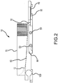
FIG. 2 illustrates a side view of a heat exchanger having an integrated heat pipe attachment and integrated spring mount in accordance with various embodiments; -
FIG. 3 illustrates a bottom view of a heat exchanger having an integrated heat pipe attachment and integrated spring mount in accordance with various embodiments; -
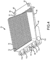
FIG. 4 illustrates a heat exchanger having an integrated heat pipe attachment and integrated spring mount in accordance with various embodiments; -
FIG. 5 illustrates a bottom view of a heat exchanger having an integrated heat pipe attachment in accordance with various embodiments; -
FIG. 6 illustrates a heat exchanger installed in an electronic device in accordance with various embodiments; -
FIG. 7 illustrates a heat exchanger and a cooling fan installed in an electronic device in accordance with various embodiments; and -
FIG. 8 illustrates a heat exchanger and a cover installed in an electronic device in accordance with various embodiments. - The detailed description of exemplary embodiments herein makes reference to the accompanying drawings, which show exemplary embodiments by way of illustration and their best mode.
- Thus, the detailed description herein is presented for purposes of illustration only and not of limitation. For example, the steps recited in any of the method or process descriptions may be executed in any order and are not necessarily limited to the order presented.
- Furthermore, any reference to singular includes plural embodiments, and any reference to more than one component or step may include a singular embodiment or step. Also, any reference to attached, fixed, connected or the like may include permanent, removable, temporary, partial, full and/or any other possible attachment option. Additionally, any reference to without contact (or similar phrases) may also include reduced contact or minimal contact.
- As used herein, phrases such as "make contact with," "coupled to," "touch," "interface with" and "engage" may be used interchangeably.
- In various embodiments, the present disclosure provides a heat exchanger system with improved heat transfer and an ability to dissipate heat from multiple sources with a reduced footprint. In this regard, a single heat exchange system may accept heat originating from multiple sources throughout a device. In various embodiments, this functionality beneficially decreases the footprint occupied by heat exchanger hardware.
- In various embodiments, a heat exchanger system may comprise a base, a mounting apparatus, a dissipation member, and a heat generator attachment site. A heat exchanger system may further comprise a gasket shelf.
- For example, with reference to
Fig. 1 , in various embodiments, aheat exchanger system 10 may comprise abase 30, integratedspring mount 40, agasket shelf 60, adissipation member 70, and heat generator attachment sites, for example, a bolt-onheat pipe attachment 80 and an integrated heatpipe clamp attachment 100. In various embodiments, integratedspring mount 40 may comprise any suitable mounting apparatus. However, a heat exchanger system may comprise any number or configuration of heat generator attachment sites. For example, with reference toFig. 3 , aheat exchanger system 10 may also comprise a pressuremount attachment site 90. - Moreover, with reference to
Fig. 4 , aspects of various other embodiments are disclosed wherein these embodiments share many of the features discussed with respect to various embodiments according toFig. 1 and wherein these embodiments may comprise a different number and configuration of heat generator attachment sites. In various embodiments, aheat exchanger system 20 may comprise abase 30, a mounting apparatus comprising astatic mount 45, agasket shelf 60, adissipation member 70, and heat generator attachment sites, for example, a bolt-onheat pipe attachment 80, and an integrated heatpipe clamp attachment 100. Thus, as illustrated herein, a heat exchanger system may comprise any number or configuration of heat generator attachment sites adapted to accept heat originating from one or more sources throughout a device. - In accordance with various embodiments, a
base 30 may comprise a unitary milled block of material. For example, abase 30 may be formed through destructive manufacturing processes performed on a piece of billet metal. For example, a solid block of copper or other material may be milled, machined, or otherwise manufactured whereby it is shaped intobase 30. In various embodiments, however, abase 30 may be manufactured through additive manufacturing processes, for example, 3D printing. Moreover, abase 30 may be comprised of copper. In various embodiments abase 30 may be comprised of aluminum, or steel, or any thermally conductive material. - With reference to
FIG. 1 , in accordance with various embodiments, thesystem 10 may comprise a mounting apparatus comprising an integratedspring mount 40. For example,base 30 may incorporate one or more integratedspring mounts 40 wherein the integratedspring mounts 40 can be attached to an electronic device via one or morefastening apparatus 50. Fasteningapparatus 50 may comprise an aperture. In various embodiments, fasteningapparatus 50 may comprise a fastener, a threaded hole, a captive bolt, a captive nut and/or any other apparatus or combination of apparatuses suitable for holding, maintaining, or otherwise coupling, or retaining thebase 30 in thermal communication with an underlying device. The underlying device may comprise a first heat source. In various embodiments, the underlying device may comprise a processor, or SOIC, ASIC, or IC, or transistor, or any device requiring heat exchange. - In various embodiments, integrated
spring mount 40 comprises a finger-like extension which may flex and draw thebase 30 into contact with the underlying device, thereby maintaining a contact force upon the underlying device. In various embodiments, abase 30 may have three integratedspring mounts 40, for example, one centered along the one side of thebase 30, for example, a side parallel to the Y-axis and perpendicular to the X-axis, crossing the negative X-axis. For further example, two integratedspring mounts 40 may then be located along another side of thebase 30, for example, a side parallel to the Y-axis and perpendicular to the X-axis, crossing the positive X-axis, wherein oneintegrated spring mount 40 is positioned at each end of the side, for instance, +Y end of the side and at the -Y end of the side, with reference to a coordinate system originating from a point at the center of thebase 30. - With reference to
Fig. 4 , in various embodiments, thesystem 20 may comprise a mounting apparatus comprising astatic mount 45. For example,base 30 may incorporate astatic mount 45 wherein thestatic mount 45 can be attached to an electronic device via one ormore fastening apparatus 50. In various embodiments, a base may have twostatic mounts 45. For example, a firststatic mount 45 may be centered along the one side of the base, for example, a side parallel to the Y-axis and perpendicular to the X-axis, crossing the negative X-axis, wherein thisstatic mount 45 has onefastening apparatus 50. For further example, a secondstatic mount 45 may also extend along another side of the base, for example, the length of a side parallel to the Y-axis and perpendicular to the X-axis, crossing the positive X-axis, wherein onefastening apparatus 50 is positioned at each end of the length, for instance, +Y end of the side and at the -Y end of the side, with reference to a coordinate system originating from a point at the center of thebase 30. - In accordance with the present invention, a heat generator attachment site is an integrated heat
pipe clamp attachment 100. With reference toFigs. 1 ,2 ,4 , and6 , in accordance with the present invention, the heatpipe clamp attachment 100 comprises a cylindrical aperture inbase 30. The aperture may traverse the entire length of a side of thebase 30, or a portion of the length of a side of thebase 30. In various embodiments, the aperture may traverse the entire length of a side of the base 30 wherein the aperture traverses a side parallel to the Y axis, and extends through the entire body of the base 30 from the negative most point the base occupies along the X axis, to the positive most point the base occupies along the X axis. The aperture lies parallel to the Y-axis, and extends into the body ofbase 30. In various embodiments, the aperture may penetrate in any depth and any direction suited to retain a heat pipe in thermal conduction withbase 30. In various embodiments, the aperture may extend from the edge of the base 30 crossing the negative X-axis to the edge of the base 30 crossing the positive X-axis. Moreover, the aperture may be trapezoidal, square, rectangular, or any shape adapted to interface in mechanical and thermal communication with a heat pipe. The aperture may have any depth or shape adapted to interface in mechanical and thermal communication with a heat pipe. - With reference to
Figs. 1 ,4 , and5 , a groove may traverse the length of the aperture, traversing parallel to the aperture which in various embodiments parallels the Y-axis, whereby one ormore fastening apparatus 110 may permit fasteners to compress the integrated heatpipe clamp attachment 100 thereby retaining aheat pipe 120 in mechanical and thermal communication with thebase 30. As used herein, thermal communication means capability for any form of heat transfer, such as conduction, convection, and radiation, whether directly, or through another body. In various embodiments,fastening apparatus 110 may comprise an aperture and a threaded hole. In various embodiments,fastening apparatus 110 may comprise a fastener, or a captive bolt, or a captive nut or any other apparatus or combination of apparatuses suitable for holding, maintaining, or otherwise coupling, or retaining aheat pipe 120 in mechanical and thermal communication with thebase 30. - In various embodiments, an additional heat generator attachment site may be a bolt-on
heat pipe attachment 80. For example, with reference toFigs. 1-5 , and with particular reference toFig. 2 , an aperture may be formed in thebase 30 wherein a heat pipe may be placed and attached via one or more fastening apparatus 50 (seeFig. 2 ). - In various embodiments, a further or alternative additional heat generator attachment site may be a pressure
mount attachment site 90. For example, with reference toFig. 3 , a pressuremount attachment site 90 may be formed in the underside of thebase 30. In various embodiments, a pressuremount attachment site 90 comprises a flat recessed region suitable for contacting an electronic device, for example, a processor, or a SOIC, or ASIC, or an IC, or a transistor, or any device that requires heat exchange. In this regard, with additional reference toFig. 1 , integrated spring mounts 40 may provide a mating force wherebybase 30 is held in mechanical and thermal communication with the processor, or SOIC, ASIC, or IC, or transistor, or any device requiring heat exchange. - In various embodiments, a heat exchanger system may comprise multiple heat generator attachment sites. For example, with reference to
Figs. 1-3 , aheat exchanger system 10 may comprise a bolt-onheat pipe attachment 80, an integrated heatpipe clamp attachment 100, and a pressuremount attachment site 90. With reference toFigs. 4 and5 , aheat exchanger system 20 may comprise a bolt-onheat pipe attachment 80 and an integrated heatpipe clamp attachment 100. However, a heat exchanger system may comprise any number, arrangement, or selection of heat generator attachment sites. - In accordance with the present invention, a
dissipation member 70 is a set of fins and troughs, for air cooling. With reference toFigs. 1 and4 , a set of fins extends upward in the direction of the positive Z-axis frombase 30. With reference toFig. 2 , a set of fins terminates in a plane substantially parallel to a plane defined by the bottom face ofbase 30. A set of troughs alternates between the fins. Thedissipation member 70 joinsbase 30 according to a curve to make room for integrated heatpipe clamp attachment 100, yet provide sufficient material to conduct heat away from integrated heatpipe clamp attachment 100. With reference toFigs. 1 and4 ,line 12 defines the curve, along whichdissipation member 70 andbase 30 interface (theline 12 is however not visible inFig. 4 ). In this regard, the troughs extend no deeper thanline 12. Thus,base 30 may comprise sufficient material in proximity to integrated heatpipe clamp attachment 100 to conduct sufficient heat away from integrated heatpipe clamp attachment 100 and intodissipation member 70. In various embodiments,dissipation member 70 andbase 30 comprise a unitary piece of material. - The troughs are oriented perpendicular to the integrated heat
pipe clamp attachment 100, and the troughs comprise a radiused end whereby the profile of the troughs is shallower near to the integrated heatpipe clamp attachment 100 and deeper extending away from the integrated heatpipe clamp attachment 100. - In various embodiments, a
gasket shelf 60 may surround the perimeter ofbase 30. For example, with reference toFigs. 1 and4 , agasket shelf 60 may surround the perimeter ofbase 30. Thegasket shelf 60 follows an angle whereby thegasket shelf 60 lies above the integrated heat pipe clamp attachment 100 (in the positive Z direction), yet declines in a negative Z direction as it extends about the parameter ofbase 30 in the positive X direction. In this manner, the exposure ofdissipation member 70 abovegasket shelf 60 may be maximized, without causing integrated heatpipe clamp attachment 100 to be exposed above thegasket shelf 60. However, any shape or configuration ofgasket shelf 60 may be implemented wherein a gasket may be placed on thegasket shelf 60 to seal thedissipation member 70 and fan 130 (seeFig. 7 ) from various surrounding hardware. - With reference to
Fig. 7 , in various embodiments, a heat exchanger system may also comprise afan 130. In various embodiments,fan 130 may intake air and blow the air across thedissipation member 70 of a heat exchanger system. With reference toFigs. 7 and 8 , this air may travel into and out of the system according to direction ofairflow 81. In various embodiments, the direction ofairflow 81 comprises parallel paths lying normal to the surface of the device in which the system is installed (e.g., normal to the plane of cover 140). In this regard, the air travels down the troughs of thedissipation member 70, and conveys heat away from the heat exchanger. In various embodiments, the radius redirects the air to exit along a path substantially parallel to the path along which the air entered the fan, for example along a path normal to the plane of the outer face offan 130, for example, according to direction ofairflow 81. In this manner, the air may enter and exit the heat exchanger system through the same side of the system. As a result, various benefits may be realized, for example, only one side of the system is utilized for entry/exit of cooling air, airflow through the heat exchanger may be improved and noise may be ameliorated, for example, as a result of the radiusing of the troughs, external transmission of noise may be ameliorated, and various other benefits. With reference toFig. 8 , in various embodiments, a heat exchanger system may further comprise acover 140. In various embodiments,cover 140 comprises apertures through which air may flow. - Now, having described various components of heat exchanger systems, a heat exchanger system may be manufactured by various methods. For example, with reference to
Figs. 1 and4 , adissipation member 70 comprising a set of fins and troughs may be manufactured by a ganged slot cutter tool. In various embodiments, a series of slot cutters are ganged together to create a ganged slot cutter tool, for example, to create all the fins and troughs in a single pass. In various embodiments, a series of slot cutters are shaped to cut troughs having a radius. However, any tool or process may be implemented whereby the fins and toughs are created in a single pass and the troughs are created having a radius, for example, according toline 12. -
Gasket shelf 60 may be manufactured by a cutting tool traversing an inclined tool path. For example, a cutting tool may transit the perimeter ofbase 30 creating an inclined gasket shelf. In this regard, the gasket shelf may follow an angle whereby thegasket shelf 60 lies above the integrated heatpipe clamp attachment 100 in the positive Z direction, yet declines in a negative Z direction as it extends in the positive X direction so as to lie beneath thedissipation member 70 atfan 130. - Now, having described various components of heat exchanger systems, a heat exchanger system may be manufactured from various materials. In various embodiments, a heat exchanger system may comprise copper. However, in further embodiments, a heat exchanger system may comprise other metals, such as aluminum, titanium, tungsten, carbon steel, or stainless steel, though it may further comprise numerous other materials configured to provide thermal conductivity. In various embodiments, various portions of heat exchanger systems as disclosed herein are made of different materials or combinations of materials, and/or may comprise coatings.
- In various embodiments, heat exchanger systems may comprise multiple materials, or any material configuration suitable to enhance or reinforce the resiliency and/or support of the system when subjected to wear in an operating environment or to satisfy other desired electromagnetic, chemical, physical, or biological properties such as heat capacity, thermal dissipation, and footprint constraints, among others.
- In various embodiments, the present disclosure provides a heat exchanger system with improved heat transfer and an ability to dissipate heat from multiple sources with a reduced footprint. Moreover, the heat exchanger system provides for airflow input and airflow output across a single plane.
- In various embodiments, while the heat exchanger systems described herein have been described in the context of electronic device applications, one will appreciate in light of the present disclosure, that the heat exchanger systems described herein may be used on various other applications such as, for example, air conditioning systems, heating systems, and industrial systems or processes. Moreover, the heat exchanger systems described herein may be employed with any heat source in any installation. In various embodiments, the heat exchanger systems described herein are used in the context of a cockpit device for use in an aircraft. Thus, in various embodiments, the heat exchanger systems described herein provide a cost effective and compact heat exchange system.
Claims (12)
- A heat exchanger system (10;20) comprising:a base (30) having a mounting apparatus configured to secure the base (30) in a substantially fixed position with respect to a first heat source;a first heat generator attachment site formed in the base (30) and conducting heat to the base (30), the first heat generator attachment site configured to be positioned in thermal communication with a first heat source; anda dissipation member (70) configured to conduct heat away from the base (30) wherein the dissipation device (70) comprises a set of alternating fins and troughs, wherein the troughs are oriented perpendicular to the first heat generator attachment site, wherein the first generator attachment site comprises an integrated heat pipe clamp attachment (100) comprising a cylindrical aperture in the base (30) that extends into the body of the base (30) parallel to an axis (Y) of the base (30), wherein the troughs are orientated perpendicular to the axis (Y), and characterised in thatthe troughs comprise a radiused end whereby the profile of the troughs is shallower near to the integrated heat pipe clamp attachment (100) and deeper extending away from the integrated heat pipe clamp attachment (100) defining a curved line (12) along which the dissipation member (70) interfaces with the base (30).
- The system of claim 1, wherein the mounting apparatus further comprises a static mount (45).
- The system of claim 1 or 2, wherein the mounting apparatus further comprises an integrated spring mount (40).
- The system of claim 1, 2 or 3, further comprising a gasket shelf (60) surrounding the perimeter of the base (30) and adapted to receive a gasket.
- The system of any preceding claim, wherein the system (10;20) further comprises:a second heat generator attachment site formed in the base (30) and configured to be positioned in thermal communication with a second heat source; anda third heat generator attachment site formed in the base (30) and configured to be positioned in thermal communication with a third heat source,wherein the second heat generator attachment site comprises a bolt-on heat pipe attachment (80), andwherein the third heat generator attachment site comprises a pressure mount attachment site (90).
- The system of any of claims 1 to 4, wherein the system further comprises:a second heat generator attachment site formed in the base and configured to be positioned in thermal communication with a second heat source and conduct heat to the base (30); andwherein the second heat generator attachment site comprises a bolt-on heat pipe attachment (80).
- The system of any preceding claim, wherein the system (10;20) comprises a unitary piece of material.
- The system of any preceding claim, further comprising a fan (130) installed to direct airflow (81) over the dissipation member.
- A method of provisioning a heat source with a cooling system comprising:securing a base (30) of the cooling system in a substantially fixed position with respect to a first heat source via a mounting apparatus;positioning a first heat generator attachment site formed in the base (30) in thermal communication with the first heat source; andconducting heat from the first heat source to the base (30);conducting heat from the base to a dissipation member (70), wherein the dissipation device (70) comprises a set of alternating fins and troughs, wherein the troughs are oriented perpendicular to the first heat generator attachment site, wherein the first generator attachment site comprises an integrated heat pipe clamp attachment (100) comprising a cylindrical aperture in the base (30) that extends into the body of the base (30) parallel to an axis (Y) of the base (30), wherein the troughs are orientated perpendicular to the axis (Y), and characterised in thatthe troughs comprise a radiused end whereby the profile of the troughs is shallower near to the integrated heat pipe clamp attachment (100) and deeper extending away from the integrated heat pipe clamp attachment (100) defining a curved line (12) along which the dissipation member (70) interfaces with the base (30).
- The method of claim 9, further comprising:installing a gasket on a gasket shelf (60) surrounding the perimeter of the base (30) and adapted to receive the gasket; andcutting the fins and troughs in the base (30) to form the dissipation member (70).
- The method of claim 9 or 10, further comprising directing airflow (81) over the dissipation member (70) to conduct heat away from the dissipation member (70).
- The method of claim 11, wherein the directing comprises directing the airflow (81) to exit the cooling system and to enter the cooling system on substantially parallel paths substantially normal to a plane.
Applications Claiming Priority (1)
| Application Number | Priority Date | Filing Date | Title |
|---|---|---|---|
| US14/152,677 US9854707B2 (en) | 2014-01-10 | 2014-01-10 | Integrated pipe heat exchanger |
Publications (2)
| Publication Number | Publication Date |
|---|---|
| EP2894666A1 EP2894666A1 (en) | 2015-07-15 |
| EP2894666B1 true EP2894666B1 (en) | 2018-12-26 |
Family
ID=52394895
Family Applications (1)
| Application Number | Title | Priority Date | Filing Date |
|---|---|---|---|
| EP15150254.9A Active EP2894666B1 (en) | 2014-01-10 | 2015-01-07 | Integrated pipe heat exchanger and method of provisioning a heat source with such an exchanger |
Country Status (6)
| Country | Link |
|---|---|
| US (1) | US9854707B2 (en) |
| EP (1) | EP2894666B1 (en) |
| JP (1) | JP6440499B2 (en) |
| CN (1) | CN104780741B (en) |
| BR (1) | BR102014031533B1 (en) |
| CA (1) | CA2875006C (en) |
Families Citing this family (6)
| Publication number | Priority date | Publication date | Assignee | Title |
|---|---|---|---|---|
| US9904595B1 (en) | 2016-08-23 | 2018-02-27 | Texas Instruments Incorporated | Error correction hardware with fault detection |
| US10458718B2 (en) * | 2017-11-29 | 2019-10-29 | Asia Vital Components Co., Ltd. | Airtight penetration structure for heat dissipation device |
| US11015872B2 (en) | 2018-06-29 | 2021-05-25 | The Boeing Company | Additively manufactured heat transfer device |
| CN109227082A (en) * | 2018-10-18 | 2019-01-18 | 中山铨展五金科技有限公司 | Automatic FIN machine of wearing of radiator |
| CN112815758B (en) * | 2020-12-30 | 2022-11-04 | 成都威诺电子设备制造有限责任公司 | Intelligent air-cooled radiator |
| CN114850797B (en) * | 2022-05-18 | 2023-11-03 | 浙江华鑫实业有限公司 | Processing method of radiator for communication |
Citations (1)
| Publication number | Priority date | Publication date | Assignee | Title |
|---|---|---|---|---|
| US20090229789A1 (en) * | 2008-03-13 | 2009-09-17 | Asia Vital Components Co., Ltd. | Radiating fin assembly for thermal module |
Family Cites Families (14)
| Publication number | Priority date | Publication date | Assignee | Title |
|---|---|---|---|---|
| JPH04369390A (en) * | 1991-06-14 | 1992-12-22 | Fujitsu Ltd | Heat pipe mounting structure |
| JPH0536897U (en) * | 1991-10-11 | 1993-05-18 | 古河電気工業株式会社 | Heat pipe radiator |
| JPH0888299A (en) * | 1994-09-19 | 1996-04-02 | Fujitsu Ltd | Semiconductor device |
| US5886408A (en) | 1994-09-08 | 1999-03-23 | Fujitsu Limited | Multi-chip semiconductor device |
| US6352103B1 (en) | 1996-05-22 | 2002-03-05 | Intel Corporation | High performance notebook PC cooling system |
| JP3713706B2 (en) * | 2001-09-28 | 2005-11-09 | 日本電気株式会社 | Heat dissipation structure, package assembly, and heat dissipation sheet |
| US7339787B2 (en) * | 2006-04-14 | 2008-03-04 | Inventec Corporation | Heat sink module for dissipating heat from a heat source on a motherboard |
| CN101065003A (en) * | 2006-04-24 | 2007-10-31 | 华虹精密股份有限公司 | Heat pipe radiator structure and manufacturing method thereof |
| JP4796457B2 (en) * | 2006-08-16 | 2011-10-19 | 富士通株式会社 | Equipment, arithmetic unit and heat dissipation member |
| US7950447B2 (en) * | 2007-11-08 | 2011-05-31 | Asia Vital Components, Co. Ltd. | Heat dissipation module |
| JP2012141082A (en) * | 2010-12-28 | 2012-07-26 | Fujitsu Ltd | Cooling device, and electronic apparatus |
| TWM422285U (en) * | 2011-09-21 | 2012-02-01 | Enermax Technology Corp | Liquid-cooling type improved heat exchange module |
| US8699226B2 (en) * | 2012-04-03 | 2014-04-15 | Google Inc. | Active cooling debris bypass fin pack |
| US8976528B2 (en) * | 2012-06-08 | 2015-03-10 | Apple Inc. | Fasteners and dual-thickness thermal stages in electronic devices |
-
2014
- 2014-01-10 US US14/152,677 patent/US9854707B2/en active Active
- 2014-12-10 CA CA2875006A patent/CA2875006C/en active Active
- 2014-12-16 BR BR102014031533-0A patent/BR102014031533B1/en active IP Right Grant
-
2015
- 2015-01-06 JP JP2015000600A patent/JP6440499B2/en active Active
- 2015-01-07 EP EP15150254.9A patent/EP2894666B1/en active Active
- 2015-01-09 CN CN201510010019.9A patent/CN104780741B/en active Active
Patent Citations (1)
| Publication number | Priority date | Publication date | Assignee | Title |
|---|---|---|---|---|
| US20090229789A1 (en) * | 2008-03-13 | 2009-09-17 | Asia Vital Components Co., Ltd. | Radiating fin assembly for thermal module |
Also Published As
| Publication number | Publication date |
|---|---|
| BR102014031533B1 (en) | 2020-12-15 |
| JP2015133489A (en) | 2015-07-23 |
| US9854707B2 (en) | 2017-12-26 |
| CA2875006C (en) | 2021-07-06 |
| JP6440499B2 (en) | 2018-12-19 |
| EP2894666A1 (en) | 2015-07-15 |
| US20150201529A1 (en) | 2015-07-16 |
| CN104780741B (en) | 2018-07-03 |
| BR102014031533A2 (en) | 2016-06-07 |
| CA2875006A1 (en) | 2015-07-10 |
| CN104780741A (en) | 2015-07-15 |
Similar Documents
| Publication | Publication Date | Title |
|---|---|---|
| CA2875006C (en) | Integrated pipe heat exchanger | |
| EP3222955B1 (en) | Cooling device and projection display device | |
| US8056933B2 (en) | Quick connect flange plate | |
| US20040240175A1 (en) | Fan holder and components cooling duct assembly | |
| US20090032234A1 (en) | Apparatus for transferring heat in a fin of a heat sink | |
| WO2012079042A1 (en) | Heatsink device and method | |
| JP2014093519A (en) | Heat dissipation device and heat dissipation fins thereof | |
| US20160366790A1 (en) | Heat dissipation device and heat dissipation system | |
| EP2853851A2 (en) | Heat exchanger thermal fatigue stress reduction | |
| US20210195795A1 (en) | Module, and server | |
| US10054132B2 (en) | Flow-directing motor mount | |
| CN105813433A (en) | Heat dissipation device and method of dissipating heat | |
| CN111010856A (en) | PCB circuit board heat dissipation structure and cooking utensils having the same | |
| CN106114872A (en) | Anti-rotation bracket | |
| CN106716628A (en) | Heat sink assembly and method of utilizing a heat sink assembly | |
| US20140174693A1 (en) | Configurable Cooling For Rugged Environments | |
| US20220201899A1 (en) | Electric appliance having a housing part | |
| JP2006245587A (en) | Retainer and method for holding a circuit card against a clamping surface of a chassis or heat sink | |
| JP2007005600A (en) | Heat sink and control panel and electric equipment using the same | |
| US20120118550A1 (en) | Heat dissipating device and method of manufacture thereof | |
| US20170016456A1 (en) | Fan cover with plurality of openings | |
| JP7788824B2 (en) | lighting equipment | |
| JP2017022152A (en) | Power apparatus | |
| US10640057B2 (en) | Heat shield with retention feature | |
| CN210570188U (en) | Fin assembly and radiator |
Legal Events
| Date | Code | Title | Description |
|---|---|---|---|
| PUAI | Public reference made under article 153(3) epc to a published international application that has entered the european phase |
Free format text: ORIGINAL CODE: 0009012 |
|
| 17P | Request for examination filed |
Effective date: 20150107 |
|
| AK | Designated contracting states |
Kind code of ref document: A1 Designated state(s): AL AT BE BG CH CY CZ DE DK EE ES FI FR GB GR HR HU IE IS IT LI LT LU LV MC MK MT NL NO PL PT RO RS SE SI SK SM TR |
|
| AX | Request for extension of the european patent |
Extension state: BA ME |
|
| R17P | Request for examination filed (corrected) |
Effective date: 20160114 |
|
| RBV | Designated contracting states (corrected) |
Designated state(s): AL AT BE BG CH CY CZ DE DK EE ES FI FR GB GR HR HU IE IS IT LI LT LU LV MC MK MT NL NO PL PT RO RS SE SI SK SM TR |
|
| STAA | Information on the status of an ep patent application or granted ep patent |
Free format text: STATUS: EXAMINATION IS IN PROGRESS |
|
| 17Q | First examination report despatched |
Effective date: 20171019 |
|
| GRAP | Despatch of communication of intention to grant a patent |
Free format text: ORIGINAL CODE: EPIDOSNIGR1 |
|
| STAA | Information on the status of an ep patent application or granted ep patent |
Free format text: STATUS: GRANT OF PATENT IS INTENDED |
|
| RIC1 | Information provided on ipc code assigned before grant |
Ipc: F28D 15/02 20060101ALN20180619BHEP Ipc: H01L 23/427 20060101ALI20180619BHEP Ipc: H01L 23/40 20060101AFI20180619BHEP Ipc: H05K 7/20 20060101ALN20180619BHEP |
|
| RIC1 | Information provided on ipc code assigned before grant |
Ipc: F28D 15/02 20060101ALN20180626BHEP Ipc: H01L 23/427 20060101ALI20180626BHEP Ipc: H05K 7/20 20060101ALN20180626BHEP Ipc: H01L 23/40 20060101AFI20180626BHEP |
|
| INTG | Intention to grant announced |
Effective date: 20180709 |
|
| GRAS | Grant fee paid |
Free format text: ORIGINAL CODE: EPIDOSNIGR3 |
|
| GRAA | (expected) grant |
Free format text: ORIGINAL CODE: 0009210 |
|
| STAA | Information on the status of an ep patent application or granted ep patent |
Free format text: STATUS: THE PATENT HAS BEEN GRANTED |
|
| AK | Designated contracting states |
Kind code of ref document: B1 Designated state(s): AL AT BE BG CH CY CZ DE DK EE ES FI FR GB GR HR HU IE IS IT LI LT LU LV MC MK MT NL NO PL PT RO RS SE SI SK SM TR |
|
| REG | Reference to a national code |
Ref country code: GB Ref legal event code: FG4D |
|
| REG | Reference to a national code |
Ref country code: CH Ref legal event code: EP |
|
| REG | Reference to a national code |
Ref country code: AT Ref legal event code: REF Ref document number: 1082605 Country of ref document: AT Kind code of ref document: T Effective date: 20190115 |
|
| REG | Reference to a national code |
Ref country code: DE Ref legal event code: R096 Ref document number: 602015022085 Country of ref document: DE |
|
| REG | Reference to a national code |
Ref country code: IE Ref legal event code: FG4D |
|
| PG25 | Lapsed in a contracting state [announced via postgrant information from national office to epo] |
Ref country code: BG Free format text: LAPSE BECAUSE OF FAILURE TO SUBMIT A TRANSLATION OF THE DESCRIPTION OR TO PAY THE FEE WITHIN THE PRESCRIBED TIME-LIMIT Effective date: 20190326 Ref country code: HR Free format text: LAPSE BECAUSE OF FAILURE TO SUBMIT A TRANSLATION OF THE DESCRIPTION OR TO PAY THE FEE WITHIN THE PRESCRIBED TIME-LIMIT Effective date: 20181226 Ref country code: NO Free format text: LAPSE BECAUSE OF FAILURE TO SUBMIT A TRANSLATION OF THE DESCRIPTION OR TO PAY THE FEE WITHIN THE PRESCRIBED TIME-LIMIT Effective date: 20190326 Ref country code: LV Free format text: LAPSE BECAUSE OF FAILURE TO SUBMIT A TRANSLATION OF THE DESCRIPTION OR TO PAY THE FEE WITHIN THE PRESCRIBED TIME-LIMIT Effective date: 20181226 Ref country code: LT Free format text: LAPSE BECAUSE OF FAILURE TO SUBMIT A TRANSLATION OF THE DESCRIPTION OR TO PAY THE FEE WITHIN THE PRESCRIBED TIME-LIMIT Effective date: 20181226 Ref country code: FI Free format text: LAPSE BECAUSE OF FAILURE TO SUBMIT A TRANSLATION OF THE DESCRIPTION OR TO PAY THE FEE WITHIN THE PRESCRIBED TIME-LIMIT Effective date: 20181226 |
|
| REG | Reference to a national code |
Ref country code: NL Ref legal event code: MP Effective date: 20181226 |
|
| REG | Reference to a national code |
Ref country code: LT Ref legal event code: MG4D |
|
| PG25 | Lapsed in a contracting state [announced via postgrant information from national office to epo] |
Ref country code: SE Free format text: LAPSE BECAUSE OF FAILURE TO SUBMIT A TRANSLATION OF THE DESCRIPTION OR TO PAY THE FEE WITHIN THE PRESCRIBED TIME-LIMIT Effective date: 20181226 Ref country code: AL Free format text: LAPSE BECAUSE OF FAILURE TO SUBMIT A TRANSLATION OF THE DESCRIPTION OR TO PAY THE FEE WITHIN THE PRESCRIBED TIME-LIMIT Effective date: 20181226 Ref country code: RS Free format text: LAPSE BECAUSE OF FAILURE TO SUBMIT A TRANSLATION OF THE DESCRIPTION OR TO PAY THE FEE WITHIN THE PRESCRIBED TIME-LIMIT Effective date: 20181226 Ref country code: GR Free format text: LAPSE BECAUSE OF FAILURE TO SUBMIT A TRANSLATION OF THE DESCRIPTION OR TO PAY THE FEE WITHIN THE PRESCRIBED TIME-LIMIT Effective date: 20190327 |
|
| REG | Reference to a national code |
Ref country code: AT Ref legal event code: MK05 Ref document number: 1082605 Country of ref document: AT Kind code of ref document: T Effective date: 20181226 |
|
| PG25 | Lapsed in a contracting state [announced via postgrant information from national office to epo] |
Ref country code: NL Free format text: LAPSE BECAUSE OF FAILURE TO SUBMIT A TRANSLATION OF THE DESCRIPTION OR TO PAY THE FEE WITHIN THE PRESCRIBED TIME-LIMIT Effective date: 20181226 |
|
| PG25 | Lapsed in a contracting state [announced via postgrant information from national office to epo] |
Ref country code: PT Free format text: LAPSE BECAUSE OF FAILURE TO SUBMIT A TRANSLATION OF THE DESCRIPTION OR TO PAY THE FEE WITHIN THE PRESCRIBED TIME-LIMIT Effective date: 20190426 Ref country code: CZ Free format text: LAPSE BECAUSE OF FAILURE TO SUBMIT A TRANSLATION OF THE DESCRIPTION OR TO PAY THE FEE WITHIN THE PRESCRIBED TIME-LIMIT Effective date: 20181226 Ref country code: IT Free format text: LAPSE BECAUSE OF FAILURE TO SUBMIT A TRANSLATION OF THE DESCRIPTION OR TO PAY THE FEE WITHIN THE PRESCRIBED TIME-LIMIT Effective date: 20181226 Ref country code: PL Free format text: LAPSE BECAUSE OF FAILURE TO SUBMIT A TRANSLATION OF THE DESCRIPTION OR TO PAY THE FEE WITHIN THE PRESCRIBED TIME-LIMIT Effective date: 20181226 Ref country code: ES Free format text: LAPSE BECAUSE OF FAILURE TO SUBMIT A TRANSLATION OF THE DESCRIPTION OR TO PAY THE FEE WITHIN THE PRESCRIBED TIME-LIMIT Effective date: 20181226 |
|
| PG25 | Lapsed in a contracting state [announced via postgrant information from national office to epo] |
Ref country code: EE Free format text: LAPSE BECAUSE OF FAILURE TO SUBMIT A TRANSLATION OF THE DESCRIPTION OR TO PAY THE FEE WITHIN THE PRESCRIBED TIME-LIMIT Effective date: 20181226 Ref country code: SM Free format text: LAPSE BECAUSE OF FAILURE TO SUBMIT A TRANSLATION OF THE DESCRIPTION OR TO PAY THE FEE WITHIN THE PRESCRIBED TIME-LIMIT Effective date: 20181226 Ref country code: SK Free format text: LAPSE BECAUSE OF FAILURE TO SUBMIT A TRANSLATION OF THE DESCRIPTION OR TO PAY THE FEE WITHIN THE PRESCRIBED TIME-LIMIT Effective date: 20181226 Ref country code: RO Free format text: LAPSE BECAUSE OF FAILURE TO SUBMIT A TRANSLATION OF THE DESCRIPTION OR TO PAY THE FEE WITHIN THE PRESCRIBED TIME-LIMIT Effective date: 20181226 Ref country code: IS Free format text: LAPSE BECAUSE OF FAILURE TO SUBMIT A TRANSLATION OF THE DESCRIPTION OR TO PAY THE FEE WITHIN THE PRESCRIBED TIME-LIMIT Effective date: 20190426 |
|
| REG | Reference to a national code |
Ref country code: CH Ref legal event code: PL |
|
| REG | Reference to a national code |
Ref country code: DE Ref legal event code: R097 Ref document number: 602015022085 Country of ref document: DE |
|
| PG25 | Lapsed in a contracting state [announced via postgrant information from national office to epo] |
Ref country code: LU Free format text: LAPSE BECAUSE OF NON-PAYMENT OF DUE FEES Effective date: 20190107 |
|
| REG | Reference to a national code |
Ref country code: BE Ref legal event code: MM Effective date: 20190131 |
|
| REG | Reference to a national code |
Ref country code: IE Ref legal event code: MM4A |
|
| PG25 | Lapsed in a contracting state [announced via postgrant information from national office to epo] |
Ref country code: MC Free format text: LAPSE BECAUSE OF FAILURE TO SUBMIT A TRANSLATION OF THE DESCRIPTION OR TO PAY THE FEE WITHIN THE PRESCRIBED TIME-LIMIT Effective date: 20181226 Ref country code: AT Free format text: LAPSE BECAUSE OF FAILURE TO SUBMIT A TRANSLATION OF THE DESCRIPTION OR TO PAY THE FEE WITHIN THE PRESCRIBED TIME-LIMIT Effective date: 20181226 Ref country code: DK Free format text: LAPSE BECAUSE OF FAILURE TO SUBMIT A TRANSLATION OF THE DESCRIPTION OR TO PAY THE FEE WITHIN THE PRESCRIBED TIME-LIMIT Effective date: 20181226 |
|
| PLBE | No opposition filed within time limit |
Free format text: ORIGINAL CODE: 0009261 |
|
| STAA | Information on the status of an ep patent application or granted ep patent |
Free format text: STATUS: NO OPPOSITION FILED WITHIN TIME LIMIT |
|
| PG25 | Lapsed in a contracting state [announced via postgrant information from national office to epo] |
Ref country code: BE Free format text: LAPSE BECAUSE OF NON-PAYMENT OF DUE FEES Effective date: 20190131 |
|
| 26N | No opposition filed |
Effective date: 20190927 |
|
| PG25 | Lapsed in a contracting state [announced via postgrant information from national office to epo] |
Ref country code: LI Free format text: LAPSE BECAUSE OF NON-PAYMENT OF DUE FEES Effective date: 20190131 Ref country code: CH Free format text: LAPSE BECAUSE OF NON-PAYMENT OF DUE FEES Effective date: 20190131 |
|
| PG25 | Lapsed in a contracting state [announced via postgrant information from national office to epo] |
Ref country code: IE Free format text: LAPSE BECAUSE OF NON-PAYMENT OF DUE FEES Effective date: 20190107 |
|
| PG25 | Lapsed in a contracting state [announced via postgrant information from national office to epo] |
Ref country code: SI Free format text: LAPSE BECAUSE OF FAILURE TO SUBMIT A TRANSLATION OF THE DESCRIPTION OR TO PAY THE FEE WITHIN THE PRESCRIBED TIME-LIMIT Effective date: 20181226 |
|
| PG25 | Lapsed in a contracting state [announced via postgrant information from national office to epo] |
Ref country code: TR Free format text: LAPSE BECAUSE OF FAILURE TO SUBMIT A TRANSLATION OF THE DESCRIPTION OR TO PAY THE FEE WITHIN THE PRESCRIBED TIME-LIMIT Effective date: 20181226 |
|
| PG25 | Lapsed in a contracting state [announced via postgrant information from national office to epo] |
Ref country code: MT Free format text: LAPSE BECAUSE OF NON-PAYMENT OF DUE FEES Effective date: 20190107 |
|
| PG25 | Lapsed in a contracting state [announced via postgrant information from national office to epo] |
Ref country code: CY Free format text: LAPSE BECAUSE OF FAILURE TO SUBMIT A TRANSLATION OF THE DESCRIPTION OR TO PAY THE FEE WITHIN THE PRESCRIBED TIME-LIMIT Effective date: 20181226 |
|
| PG25 | Lapsed in a contracting state [announced via postgrant information from national office to epo] |
Ref country code: HU Free format text: LAPSE BECAUSE OF FAILURE TO SUBMIT A TRANSLATION OF THE DESCRIPTION OR TO PAY THE FEE WITHIN THE PRESCRIBED TIME-LIMIT; INVALID AB INITIO Effective date: 20150107 |
|
| PG25 | Lapsed in a contracting state [announced via postgrant information from national office to epo] |
Ref country code: MK Free format text: LAPSE BECAUSE OF FAILURE TO SUBMIT A TRANSLATION OF THE DESCRIPTION OR TO PAY THE FEE WITHIN THE PRESCRIBED TIME-LIMIT Effective date: 20181226 |
|
| REG | Reference to a national code |
Ref country code: DE Ref legal event code: R079 Ref document number: 602015022085 Country of ref document: DE Free format text: PREVIOUS MAIN CLASS: H01L0023400000 Ipc: H10W0040600000 |
|
| PGFP | Annual fee paid to national office [announced via postgrant information from national office to epo] |
Ref country code: GB Payment date: 20251220 Year of fee payment: 12 |
|
| P01 | Opt-out of the competence of the unified patent court (upc) registered |
Free format text: CASE NUMBER: UPC_APP_0016740_2894666/2025 Effective date: 20251210 |
|
| PGFP | Annual fee paid to national office [announced via postgrant information from national office to epo] |
Ref country code: FR Payment date: 20251217 Year of fee payment: 12 |
|
| PGFP | Annual fee paid to national office [announced via postgrant information from national office to epo] |
Ref country code: DE Payment date: 20251217 Year of fee payment: 12 |