EP2894408A1 - Method for controlling the temperature in the rooms of a building - Google Patents
Method for controlling the temperature in the rooms of a building Download PDFInfo
- Publication number
- EP2894408A1 EP2894408A1 EP14151038.8A EP14151038A EP2894408A1 EP 2894408 A1 EP2894408 A1 EP 2894408A1 EP 14151038 A EP14151038 A EP 14151038A EP 2894408 A1 EP2894408 A1 EP 2894408A1
- Authority
- EP
- European Patent Office
- Prior art keywords
- heating
- building
- actuator
- rooms
- controller
- Prior art date
- Legal status (The legal status is an assumption and is not a legal conclusion. Google has not performed a legal analysis and makes no representation as to the accuracy of the status listed.)
- Granted
Links
- 238000000034 method Methods 0.000 title claims abstract description 22
- 238000010438 heat treatment Methods 0.000 claims abstract description 56
- 239000002826 coolant Substances 0.000 claims abstract description 8
- 230000005540 biological transmission Effects 0.000 claims description 4
- 230000033001 locomotion Effects 0.000 description 4
- 230000001419 dependent effect Effects 0.000 description 3
- XLYOFNOQVPJJNP-UHFFFAOYSA-N water Substances O XLYOFNOQVPJJNP-UHFFFAOYSA-N 0.000 description 3
- 239000012530 fluid Substances 0.000 description 2
- 230000006870 function Effects 0.000 description 2
- 230000001105 regulatory effect Effects 0.000 description 2
- 244000089486 Phragmites australis subsp australis Species 0.000 description 1
- 230000001276 controlling effect Effects 0.000 description 1
- 238000001816 cooling Methods 0.000 description 1
- 238000005265 energy consumption Methods 0.000 description 1
- 238000005516 engineering process Methods 0.000 description 1
- 230000004044 response Effects 0.000 description 1
- 230000006903 response to temperature Effects 0.000 description 1
Images
Classifications
-
- F—MECHANICAL ENGINEERING; LIGHTING; HEATING; WEAPONS; BLASTING
- F24—HEATING; RANGES; VENTILATING
- F24D—DOMESTIC- OR SPACE-HEATING SYSTEMS, e.g. CENTRAL HEATING SYSTEMS; DOMESTIC HOT-WATER SUPPLY SYSTEMS; ELEMENTS OR COMPONENTS THEREFOR
- F24D19/00—Details
- F24D19/10—Arrangement or mounting of control or safety devices
- F24D19/1006—Arrangement or mounting of control or safety devices for water heating systems
- F24D19/1009—Arrangement or mounting of control or safety devices for water heating systems for central heating
- F24D19/1015—Arrangement or mounting of control or safety devices for water heating systems for central heating using a valve or valves
-
- G—PHYSICS
- G05—CONTROLLING; REGULATING
- G05D—SYSTEMS FOR CONTROLLING OR REGULATING NON-ELECTRIC VARIABLES
- G05D23/00—Control of temperature
- G05D23/19—Control of temperature characterised by the use of electric means
- G05D23/1927—Control of temperature characterised by the use of electric means using a plurality of sensors
- G05D23/193—Control of temperature characterised by the use of electric means using a plurality of sensors sensing the temperaure in different places in thermal relationship with one or more spaces
- G05D23/1932—Control of temperature characterised by the use of electric means using a plurality of sensors sensing the temperaure in different places in thermal relationship with one or more spaces to control the temperature of a plurality of spaces
- G05D23/1934—Control of temperature characterised by the use of electric means using a plurality of sensors sensing the temperaure in different places in thermal relationship with one or more spaces to control the temperature of a plurality of spaces each space being provided with one sensor acting on one or more control means
-
- Y—GENERAL TAGGING OF NEW TECHNOLOGICAL DEVELOPMENTS; GENERAL TAGGING OF CROSS-SECTIONAL TECHNOLOGIES SPANNING OVER SEVERAL SECTIONS OF THE IPC; TECHNICAL SUBJECTS COVERED BY FORMER USPC CROSS-REFERENCE ART COLLECTIONS [XRACs] AND DIGESTS
- Y02—TECHNOLOGIES OR APPLICATIONS FOR MITIGATION OR ADAPTATION AGAINST CLIMATE CHANGE
- Y02B—CLIMATE CHANGE MITIGATION TECHNOLOGIES RELATED TO BUILDINGS, e.g. HOUSING, HOUSE APPLIANCES OR RELATED END-USER APPLICATIONS
- Y02B30/00—Energy efficient heating, ventilation or air conditioning [HVAC]
- Y02B30/70—Efficient control or regulation technologies, e.g. for control of refrigerant flow, motor or heating
Definitions
- the invention relates to a method for controlling the temperature of rooms of a building in which in the building a Schunikverteiler is installed, which has a controller and the number of existing heating circuits in the building corresponding number of valves, one of each in an inlet for a heating or cooling medium of a heating circuit is installed, and in which each valve is equipped with an actuator by which the flow of the heating or cooling medium determining position of the valve between an open position and a closed position is set as end positions ( DE 10 2008 051 275 A1 ).
- the temperature in the rooms of buildings of all kinds is regulated in modern technology.
- the rooms are heated or cooled depending on the outside temperature.
- a heating medium such as warm water
- a cooling medium such as chilled water
- the word "heating circuit” therefore applies both to the supply of a heat carrier and a cooling medium.
- the method according to the invention for the heating of rooms will be described, representative of a cooling, which is carried out in the same way as the heating except for the medium to be transported.
- thermostats are arranged, where a set temperature can be set.
- a signal to an installed in a Schunikverteiler arrangement by which the heat supply to the corresponding room is increased or reduced until the set temperature is reached again.
- a controller and valves are arranged, one of which is installed in the inlet for the heating medium of a heating circuit. The valves are going through with the same associated actuators in response to the signals of the thermostats of the individual rooms and controlled.
- the signals can be transmitted to the controller wired or via radio.
- a building heating system with at least two, a heating fluid comprehensive heating circuits, in which in a flow pipe for the heating fluid or in a return pipe for the same an actuator for adjusting the operation of the associated heating circuit is present.
- a distributor three actuators are provided which have an electric or electrothermal actuator.
- Actuators are used to actuate the valves, which have a temperature-dependent expansion body to which an electrical heating element, such as an electrical resistance, is mounted. Depending on the operating mode of the valves, they are either opened or closed by the actuators when the electrical heating element is connected by the regulator to a voltage source and thereby heated. A working piston of the expansion body of the respective actuating element then adjusts the plunger of the associated valve.
- This known method operates temperature-dependent and thus relatively slow. It must also be provided for the operation of the associated system, a sufficiently high power to ensure that all valves are actuated if necessary at the same time.
- the invention has for its object to make the initially described method so that it allows for reduced energy consumption a quick response to temperature changes in the rooms of the building.
- an electric motor actuated actuators are for example in the DE 10 2010 024 280 A1 described.
- the electric motors hold their position as soon as they are disconnected from the voltage source and thus the electrical current causing their operation is switched off. Therefore, if all the motors or actuators used in this method are disconnected from the power source, no power is needed to operate the associated assembly. If necessary, the rotors of the motors, regardless of thermal processes, immediately after their connection to the voltage source rotate to a new position, in which they remain stable again after disconnection from the voltage source. A correction of the temperature in a heating circuit can thus be carried out as quickly as possible by the motor of the actuator used for this heating circuit is turned on for a short time.
- This function of equipped with an electric motor actuators is exploited in the method according to the invention is particularly advantageous in that only the motor of a single actuator is turned on. Since the time required for an adjustment of the associated valve operating time is very short, the motors of all actuators, even if a temperature change is to be performed simultaneously or almost simultaneously for all heating circuits, each individually and separately connected to the voltage source. A noticeable delay in the temperature control for the individual rooms of a building does not occur. Overall, therefore, when using this method for a heating system only needs to be maintained energy for a single actuator, which is supplied by the controller to a motor or successively two or more motors for adjusting the associated valve. The room temperature in the rooms of a building is also controlled much faster using this method than in processes that work with temperature-dependent actuators.
- electric motors are used in the actuators, which may be, for example, DC motors or stepper motors. They will be referred to as "motors" in the following.
- the motors can each be equipped with electronics. However, it is also possible to provide a common for all motors electronics centrally in a controller which is arranged in a heating circuit manifold.
- a gear is connected to the motors, which acts on the plunger of the respective valve to be adjusted.
- the rotational movement of the equipped with a shaft rotor of the motors is converted by the transmission in the required translational movement.
- the relatively high speed of the rotor of the motors is converted by the transmission in a slower rectilinear motion.
- the gearbox is advantageously designed as a self-locking gearbox, which helps to maintain the stable position of the motors after they are turned off by the power source.
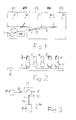
- Fig.1 shows in a very schematic representation of a view of a building G with five rooms R1 to R5, in each of which a device 1 is arranged, through which the temperature prevailing in the respective room is detected.
- a device 1 may advantageously be a sensor that detects only the actual value of the room temperature. But it can also be a sensor that detects both the actual value and the setpoint of the room temperature.
- a heating circuit manifold HK is also installed to which pipes 2, 3, 4, 5 and 6 leading to the spaces R1 to R5 are connected, which are connected to heating circuits arranged in the spaces R1 to R5.
- the tubes 2 to 6 are used to supply a heating medium, preferably water, to the heating circuits.
- heating circuits for example Surface heating systems, radiators or other heat exchangers must be installed in rooms R1 to R5. It is also possible to arrange more than one heating circuit in a room. For each of these heating circuits then leads a separate pipe.
- the number of rooms of the building G is arbitrary. It can therefore be more or less than five rooms in the building G, each having at least one heating circuit.
- a regulator 7 is also arranged in the building G, which is preferably equipped with an electronic storage function.
- the controller 7 can be supplied from the devices 1 of the individual rooms signals, either wired or via radio.
- the signals of the devices 1, for example, correspond only to the actual value of the temperature prevailing in the respective room.
- the desired value of the temperature is then stored for each room of the building G in the memory of the controller 7.
- both the actual values and the setpoint values of the room temperature are transmitted to the controller 7 as signals.
- elements arranged in the heating circuit distributor HK are regulated in the sense of equalization. These elements are based on the FIGS. 2 and 3 explained.
- a valve V is mounted, which is provided with a in Fig. 3 is surrounded by a dash-dot line bordered actuator ST.
- the tubes 2 to 6 are connected to a main tube 8, which is supplied from a supply not shown with a heating medium.
- the following statements refer to a pipe, a valve and an actuator of a heating circuit. They apply in the same sense to all heating circuits.
- the actuator ST has a motor 9, which is connectable via a switch 10 with a voltage source 11.
- the shaft 12 of the motor 9 acts (with the interposition of a transmission) accordingly Fig. 3 on the plunger 13 of the valve V, which is thereby optionally adjusted in the direction of arrow 14.
- the valve V is thereby optionally brought into its closed position.
- He is then brought by the return spring of the valve V in its open position.
- This method described for a valve V or an actuator ST is carried out for all actuators of the heating circuit HK, one after the other only for one actuator each.
- the motors of all actuators are thus independently of each other in a predeterminable order by the controller 7 respectively briefly connected by closing the switch 10 to the voltage source 11 and accordingly supplied with power.
Abstract
Es wird ein Verfahren zum Temperieren von Räumen (R1-R5) eines Gebäudes (G) angegeben, bei welchem in dem Gebäude ein Heizkreisverteiler (HK) installiert wird, der einen Regler (7) und eine der Anzahl von im Gebäude vorhandenen Heizkreisen entsprechende Anzahl von Ventilen aufweist, von denen jeweils eins in einen Zulauf für ein Heiz- bzw. Kühlmedium eines Heizkreises eingebaut wird. Jedes Ventil wird mit einem Stellantrieb ausgerüstet, durch welchen die den Durchfluß des Heiz- bzw. Kühlmediums bestimmende Stellung des Ventils zwischen einer Offenstellung und einer Schließstellung als Endpositionen eingestellt wird. Jeder Stellantrieb wird mit einem elektrischen Motor ausgerüstet und die Stellantriebe werden zur Betätigung der Ventile gegebenenfalls durch den Regler (7) einzeln und zeitlich getrennt voneinander für eine vorgegebene Zeitdauer mit einer elektrischen Spannungsquelle verbunden.The invention relates to a method for controlling rooms (R1-R5) of a building (G) in which a heating circuit distributor (HK) is installed in the building, comprising a controller (7) and a number corresponding to the number of heating circuits present in the building of valves, of which one each is installed in an inlet for a heating or cooling medium of a heating circuit. Each valve is equipped with an actuator, by which the flow of the heating or cooling medium determining position of the valve between an open position and a closed position is set as end positions. Each actuator is equipped with an electric motor and the actuators are connected to actuate the valves optionally by the controller (7) individually and separated in time for a predetermined period of time with an electrical voltage source.
Description
Die Erfindung bezieht sich auf ein Verfahren zum Temperieren von Räumen eines Gebäudes, bei welchem in dem Gebäude ein Heizkreisverteiler installiert wird, der einen Regler und eine der Anzahl von im Gebäude vorhandenen Heizkreisen entsprechende Anzahl von Ventilen aufweist, von denen jeweils eins in einen Zulauf für ein Heiz- bzw. Kühlmedium eines Heizkreises eingebaut wird, und bei welchem jedes Ventil mit einem Stellantrieb ausgerüstet wird, durch welchen die den Durchfluß des Heiz- bzw. Kühlmediums bestimmende Stellung des Ventils zwischen einer Offenstellung und einer Schließstellung als Endpositionen eingestellt wird (
Mit einem derartigen Verfahren wird in moderner Technik die Temperatur in den Räumen von Gebäuden aller Art geregelt. Dabei werden die Räume in Abhängigkeit von der Außentemperatur erwärmt oder gekühlt. In diesem Sinne wird den Räumen über in denselben installierte Heizkreise entweder ein Heizmedium, wie warmes Wasser, oder ein Kühlmedium, wie gekühltes Wasser, zugeführt. Das Wort "Heizkreis" gilt demnach sowohl für das Zuführen eines Wärmeträgers als auch eines Kühlmediums. Im folgenden wird das Verfahren nach der Erfindung für das Beheizen von Räumen beschrieben, stellvertretend auch für eine Kühlung, die bis auf das zu transportierende Medium in gleicher Weise wie die Beheizung durchgeführt wird.With such a method, the temperature in the rooms of buildings of all kinds is regulated in modern technology. The rooms are heated or cooled depending on the outside temperature. In this sense, either a heating medium, such as warm water, or a cooling medium, such as chilled water, is supplied to the rooms via heating circuits installed in the same. The word "heating circuit" therefore applies both to the supply of a heat carrier and a cooling medium. In the following, the method according to the invention for the heating of rooms will be described, representative of a cooling, which is carried out in the same way as the heating except for the medium to be transported.
In den mit den Heizkreisen ausgerüsteten Räumen sind Thermostate angeordnet, an denen eine Solltemperatur eingestellt werden kann. Bei einem Abweichen der Isttemperatur von der der Solltemperatur in einem Raum wird von dem zugehörigen Thermostat ein Signal zu einer in einem Heizkreisverteiler installierten Anordnung übertragen, durch welche die Wärmezufuhr zu dem entsprechenden Raum solange erhöht bzw. reduziert wird, bis die Solltemperatur wieder erreicht ist. Im Heizkreisverteiler sind ein Regler und Ventile angeordnet, von denen je eins in den Zulauf für das Heizmedium eines Heizkreises eingebaut ist. Die Ventile werden durch mit denselben verbundene Stellantriebe in Abhängigkeit von den Signalen der Thermostate der einzelnen Räume auf- und zugesteuert. Dabei können die Signale dem Regler leitungsgebunden oder auch über Funk übermittelt werden.In the equipped with the heating circuits thermostats are arranged, where a set temperature can be set. In a deviation of the actual temperature of the target temperature in a room is transmitted from the associated thermostat, a signal to an installed in a Heizkreisverteiler arrangement by which the heat supply to the corresponding room is increased or reduced until the set temperature is reached again. In the heating circuit manifold, a controller and valves are arranged, one of which is installed in the inlet for the heating medium of a heating circuit. The valves are going through with the same associated actuators in response to the signals of the thermostats of the individual rooms and controlled. The signals can be transmitted to the controller wired or via radio.
Aus der
Bei dem bekannten Verfahren nach der eingangs erwähnten
Der Erfindung liegt die Aufgabe zugrunde, das eingangs geschilderte Verfahren so zu gestalten, daß es bei vermindertem Energieaufwand eine schnelle Reaktion bei Temperaturänderungen in den Räumen des Gebäudes ermöglicht.The invention has for its object to make the initially described method so that it allows for reduced energy consumption a quick response to temperature changes in the rooms of the building.
Diese Aufgabe wird gemäß der Erfindung dadurch gelöst,
- daß als Stellantrieb fürjedes der Ventile ein mit einem elektrischen Motor ausgerüsteter Stellantrieb eingesetzt wird und
- daß die Stellantriebe zur Betätigung der Ventile gegebenenfalls durch den Regler einzeln und zeitlich getrennt voneinander für eine vorgegebene Zeitdauer mit einer elektrischen Spannungsquelle verbunden werden.
- that as an actuator for each of the valves equipped with an electric motor actuator is used and
- that the actuators for actuating the valves, if necessary, are connected by the controller individually and separated in time from each other for a predetermined period of time with an electrical voltage source.
Durch einen elektrischen Motor betätigte Stellantriebe sind beispielsweise in der
Diese Funktion der mit einem elektrischen Motor ausgerüsteten Stellantriebe wird bei dem Verfahren nach der Erfindung dadurch besonders vorteilhaft ausgenutzt, daß immer nur der Motor eines einzigen Stellantriebs eingeschaltet wird. Da dessen für eine Verstellung des zugehörigen Ventils benötigte Betriebsdauer sehr kurz ist, können die Motoren aller Stellantriebe auch dann, wenn für alle Heizkreise gleichzeitig oder nahezu gleichzeitig eine Temperaturänderung durchgeführt werden soll, jeweils einzeln und getrennt voneinander mit der Spannungsquelle verbunden werden. Eine merkbare Verzögerung bei der Temperaturregelung für die einzelnen Räume eines Gebäudes tritt nicht auf. Insgesamt braucht daher bei Einsatz dieses Verfahrens für eine Heizungsanlage nur Energie für einen einzigen Stellantrieb vorgehalten zu werden, die durch den Regler dem einen Motor oder nacheinander zwei oder mehr Motoren zur Verstellung des zugehörigen Ventils zugeführt wird. Die Raumtemperatur in den Räumen eines Gebäudes wird außerdem bei Einsatz dieses Verfahrens wesentlich schneller geregelt als bei Verfahren, die mit temperaturabhängigen Stellantrieben arbeiten.This function of equipped with an electric motor actuators is exploited in the method according to the invention is particularly advantageous in that only the motor of a single actuator is turned on. Since the time required for an adjustment of the associated valve operating time is very short, the motors of all actuators, even if a temperature change is to be performed simultaneously or almost simultaneously for all heating circuits, each individually and separately connected to the voltage source. A noticeable delay in the temperature control for the individual rooms of a building does not occur. Overall, therefore, when using this method for a heating system only needs to be maintained energy for a single actuator, which is supplied by the controller to a motor or successively two or more motors for adjusting the associated valve. The room temperature in the rooms of a building is also controlled much faster using this method than in processes that work with temperature-dependent actuators.
Das Verfahren nach der Erfindung wird anhand der Zeichnungen als Ausführungsbeispiel erläutert.The method according to the invention will be explained with reference to the drawings as an exemplary embodiment.
Es zeigen:
-
Fig. 1 in schematischer Darstellung ein Schnittbild eines Gebäudes mit mehreren Räumen. -
Fig. 2 eine Einzelheit ausFig. 1 in vergrößerter Darstellung. -
Fig. 3 eine Einzelheit ausFig. 2 in weiter vergrößerter Darstellung.
-
Fig. 1 a schematic representation of a sectional view of a building with several rooms. -
Fig. 2 a detailFig. 1 in an enlarged view. -
Fig. 3 a detailFig. 2 in a further enlarged view.
Bei dem Verfahren nach der Erfindung werden in den Stellantrieben elektrische Motoren eingesetzt, bei denen es sich beispielsweise um Gleichstrommotoren oder Schrittmotoren handeln kann. Sie werden im folgenden kurz als "Motoren" bezeichnet. Die Motoren können jeweils mit einer Elektronik ausgerüstet sein. Es ist jedoch auch möglich, eine für alle Motoren gemeinsame Elektronik zentral in einem Regler vorzusehen, der in einem Heizkreisverteiler angeordnet ist.In the method according to the invention electric motors are used in the actuators, which may be, for example, DC motors or stepper motors. They will be referred to as "motors" in the following. The motors can each be equipped with electronics. However, it is also possible to provide a common for all motors electronics centrally in a controller which is arranged in a heating circuit manifold.
An die Motoren ist in praktischer Ausführung ein Getriebe angeschlossen, das auf den Stößel des jeweils zu verstellenden Ventils einwirkt. Die Drehbewegung der mit einer Welle ausgerüsteten Läufer der Motoren wird durch das Getriebe in die erforderliche translatorische Bewegung umgesetzt. Außerdem wird die relativ hohe Drehzahl der Läufer der Motoren durch das Getriebe in eine langsamere geradlinige Bewegung umgewandelt. Das Getriebe ist mit Vorteil als selbsthemmendes Getriebe ausgeführt, wodurch das Einhalten der stabilen Position der Motoren nach ihrem Abschalten von der Spannungsquelle unterstützt wird. Auf den Aufbau der Motoren und ihre Funktionsweise wird in der folgenden Beschreibung nicht näher eingegangen.In a practical embodiment, a gear is connected to the motors, which acts on the plunger of the respective valve to be adjusted. The rotational movement of the equipped with a shaft rotor of the motors is converted by the transmission in the required translational movement. In addition, the relatively high speed of the rotor of the motors is converted by the transmission in a slower rectilinear motion. The gearbox is advantageously designed as a self-locking gearbox, which helps to maintain the stable position of the motors after they are turned off by the power source. The structure of the engines and their operation will not be discussed in detail in the following description.
Im Bereich des Heizkreisverteilers HK ist in dem Gebäude G außerdem ein Regler 7 angeordnet, der vorzugsweise mit einer elektronischen Speicherfunktion ausgerüstet ist. Dem Regler 7 können von den Geräten 1 der einzelnen Räume Signale zugeführt werden, und zwar entweder leitungsgebunden oder über Funk. Die Signale der Geräte 1 entsprechen beispielsweise nur dem Istwert der im jeweiligen Raum herrschenden Temperatur. Der Sollwert der Temperatur ist dann für jeden Raum des Gebäudes G im Speicher des Reglers 7 abgelegt. Bei einer Erfassung von Istwert und Sollwert der Raumtemperatur durch die Geräte 1 in den Räumen R1 bis R5 werden als Signale sowohl die Istwerte als auch die Sollwerte der Raumtemperatur zum Regler 7 übertragen. Bei einer Abweichung des Istwerts der Raumtemperatur vom im Regler 7 gespeicherten Sollwert werden im Heizkreisverteiler HK angeordnete Elemente im Ausgleichssinne geregelt. Diese Elemente werden anhand der
Im Heizkreisverteiler HK ist in jedem der Rohre 2 bis 6 ein Ventil V angebracht, das mit einem in
Der Stellantrieb ST weist einen Motor 9 auf, der über einen Schalter 10 mit einer Spannungsquelle 11 verbindbar ist. Die Welle 12 des Motors 9 wirkt (unter Zwischenschaltung eines Getriebes) entsprechend
Das Verfahren nach der Erfindung arbeitet beispielsweise wie folgt:
- Die Temperaturen in den Räumen R1 bis R5 werden durch die
Geräte 1 als Istwerte erfaßt. Die zugehörigen Sollwerte der Raumtemperaturen sindim Regler 7 gespeichert. Wenn beispielsweise die Temperatur im Raum R1 den gespeicherten Sollwert unterschreitet, wird der Motor desim Rohr 2 angeordneten Stellantriebs ST kurzzeitig durch Schließen des Schalters 10 mit Strom versorgt.Der Stößel 13 des Ventils V wird dadurch entlastet und entgegengesetzt zur Richtung des Pfeils 14 bewegt, also in Richtung der Offenstellung des Ventils V. Die Zufuhr des Heizmediums zum Heizkreis des Raumes R1 wird dadurch erhöht, so daß die Raumtemperatur steigt.Der Motor 9 wird nur kurzzeitig eingeschaltet, beispielsweise für 5 Sekunden, und dann wieder von der Spannungsquelle 11 getrennt. Nach einer vorgegebenen Zeitdauer wird ein weiterer Istwert der Temperatur im Raum R1 abgefragt und gegebenenfalls zur weiteren Betätigung desMotors 9 verwendet. Wenn die Raumtemperatur den vorgegebenen Istwert überschritten hat, wird die Drehrichtung desMotors 9 umgedreht, so daß der Stößel 13 des Ventils V mit entsprechender Drosselung der Zufuhr des Heizmediums in Richtung der Schließstellung desselben bewegt wird.
- The temperatures in the rooms R1 to R5 are detected by the
devices 1 as actual values. The associated setpoint values of the room temperatures are stored in thecontroller 7. For example, if the temperature in the room R1 falls below the stored setpoint, the motor of the arranged in thetube 2 actuator ST is briefly supplied by closing theswitch 10 with power. Theplunger 13 of the valve V is thereby relieved and opposite to the direction of thearrow 14 moves, ie in the direction of the open position of the valve V. The supply of the heating medium to the heating circuit of the room R1 is thereby increased, so that the room temperature rises. Themotor 9 is only briefly turned on, for example for 5 seconds, and then disconnected from the voltage source 11 again. After a predetermined period of time, another actual value of the temperature in the room R1 is interrogated and optionally used for further actuation of themotor 9. When the room temperature has exceeded the preset actual value, the direction of rotation of themotor 9 is reversed, so that theplunger 13 of the valve V is moved with the same throttling the supply of the heating medium in the direction of its closed position.
Dieses für ein Ventil V bzw. einen Stellantrieb ST beschriebene Verfahren wird für alle Stellantriebe des Heizkreises HK durchgeführt, und zwar nacheinander jeweils nur für einen Stellantrieb. Die Motoren aller Stellantriebe werden also unabhängig voneinander in vorgebbarer Reihenfolge durch den Regler 7 jeweils kurzzeitig durch Schließen der Schalter 10 mit der Spannungsquelle 11 verbunden und dementsprechend mit Strom versorgt.This method described for a valve V or an actuator ST is carried out for all actuators of the heating circuit HK, one after the other only for one actuator each. The motors of all actuators are thus independently of each other in a predeterminable order by the
Claims (5)
Priority Applications (3)
| Application Number | Priority Date | Filing Date | Title |
|---|---|---|---|
| ES14151038T ES2766073T3 (en) | 2014-01-14 | 2014-01-14 | Procedure for tempering rooms in a building |
| EP14151038.8A EP2894408B1 (en) | 2014-01-14 | 2014-01-14 | Method for controlling the temperature in the rooms of a building |
| DK14151038.8T DK2894408T3 (en) | 2014-01-14 | 2014-01-14 | Method for controlling the temperature in the rooms of a building |
Applications Claiming Priority (1)
| Application Number | Priority Date | Filing Date | Title |
|---|---|---|---|
| EP14151038.8A EP2894408B1 (en) | 2014-01-14 | 2014-01-14 | Method for controlling the temperature in the rooms of a building |
Publications (2)
| Publication Number | Publication Date |
|---|---|
| EP2894408A1 true EP2894408A1 (en) | 2015-07-15 |
| EP2894408B1 EP2894408B1 (en) | 2019-09-04 |
Family
ID=49949535
Family Applications (1)
| Application Number | Title | Priority Date | Filing Date |
|---|---|---|---|
| EP14151038.8A Active EP2894408B1 (en) | 2014-01-14 | 2014-01-14 | Method for controlling the temperature in the rooms of a building |
Country Status (3)
| Country | Link |
|---|---|
| EP (1) | EP2894408B1 (en) |
| DK (1) | DK2894408T3 (en) |
| ES (1) | ES2766073T3 (en) |
Cited By (2)
| Publication number | Priority date | Publication date | Assignee | Title |
|---|---|---|---|---|
| DE102017115376A1 (en) | 2017-07-10 | 2019-01-10 | Rehau Ag + Co | Method for carrying out a hydraulic balancing of a heating and / or cooling system such. B. a building |
| EP3553395A1 (en) | 2018-04-11 | 2019-10-16 | Johnson Electric International AG | Actuator, heating circuit manifold, and procedure for installing actuator in heating circuit manifold |
Citations (6)
| Publication number | Priority date | Publication date | Assignee | Title |
|---|---|---|---|---|
| WO2009072744A2 (en) * | 2007-12-07 | 2009-06-11 | Kyungdong Network Co., Ltd. | Device for control room temperature of each room adapted to heating environment and its method |
| DE102008049619A1 (en) * | 2008-09-30 | 2010-04-01 | Simplex Armaturen + Fittings Gmbh | Building heating system has two heating circuits, which have heating fluid, and electronic actual flow rate comparison arithmetic unit |
| DE102008051275A1 (en) * | 2008-10-10 | 2010-04-15 | Möhlenhoff Wärmetechnik GmbH | Method for tempering rooms of a building |
| DE102010024280A1 (en) * | 2010-06-18 | 2011-12-22 | Diehl Ako Stiftung & Co. Kg | Adjusting device, in particular for a radiator valve |
| US20120048381A1 (en) * | 2010-08-31 | 2012-03-01 | Macduff Malcolm | Supply Manifold For Hydronic System |
| EP2530390A1 (en) * | 2011-06-01 | 2012-12-05 | Danfoss A/S | Heating system and method for heating a plurality of rooms |
-
2014
- 2014-01-14 DK DK14151038.8T patent/DK2894408T3/en active
- 2014-01-14 ES ES14151038T patent/ES2766073T3/en active Active
- 2014-01-14 EP EP14151038.8A patent/EP2894408B1/en active Active
Patent Citations (6)
| Publication number | Priority date | Publication date | Assignee | Title |
|---|---|---|---|---|
| WO2009072744A2 (en) * | 2007-12-07 | 2009-06-11 | Kyungdong Network Co., Ltd. | Device for control room temperature of each room adapted to heating environment and its method |
| DE102008049619A1 (en) * | 2008-09-30 | 2010-04-01 | Simplex Armaturen + Fittings Gmbh | Building heating system has two heating circuits, which have heating fluid, and electronic actual flow rate comparison arithmetic unit |
| DE102008051275A1 (en) * | 2008-10-10 | 2010-04-15 | Möhlenhoff Wärmetechnik GmbH | Method for tempering rooms of a building |
| DE102010024280A1 (en) * | 2010-06-18 | 2011-12-22 | Diehl Ako Stiftung & Co. Kg | Adjusting device, in particular for a radiator valve |
| US20120048381A1 (en) * | 2010-08-31 | 2012-03-01 | Macduff Malcolm | Supply Manifold For Hydronic System |
| EP2530390A1 (en) * | 2011-06-01 | 2012-12-05 | Danfoss A/S | Heating system and method for heating a plurality of rooms |
Cited By (3)
| Publication number | Priority date | Publication date | Assignee | Title |
|---|---|---|---|---|
| DE102017115376A1 (en) | 2017-07-10 | 2019-01-10 | Rehau Ag + Co | Method for carrying out a hydraulic balancing of a heating and / or cooling system such. B. a building |
| EP3553395A1 (en) | 2018-04-11 | 2019-10-16 | Johnson Electric International AG | Actuator, heating circuit manifold, and procedure for installing actuator in heating circuit manifold |
| DE102018108562A1 (en) | 2018-04-11 | 2019-10-17 | Johnson Electric Germany GmbH & Co. KG | Actuator, heating circuit distributor and method for mounting the actuator in such a heating circuit manifold |
Also Published As
| Publication number | Publication date |
|---|---|
| ES2766073T3 (en) | 2020-06-11 |
| EP2894408B1 (en) | 2019-09-04 |
| DK2894408T3 (en) | 2021-09-27 |
Similar Documents
| Publication | Publication Date | Title |
|---|---|---|
| CH704462A1 (en) | Liquid-air heat exchange device with Peltier elements. | |
| DE3414481A1 (en) | DEVICE FOR CONTROLLING THE FLOW OF A LIQUID | |
| EP2435887B1 (en) | Enhanced control of a thermostatic valve | |
| EP0893581A2 (en) | Multiple way valve | |
| DE102010005275A1 (en) | Method and device for setting a tempering device | |
| EP2087290A1 (en) | Heating or cooling system | |
| EP2175206B1 (en) | Method for tempering rooms in a building | |
| EP2894408B1 (en) | Method for controlling the temperature in the rooms of a building | |
| DE102015114474A1 (en) | Heat pump system and method for operating a heat pump system | |
| DE102012015892A1 (en) | Method for controlling temperature of rooms in building, involves installing heating circuit dispatcher that is connected to rooms of building corresponding to valve that is set between open position and closed position | |
| DE716344C (en) | Temperature control of cooled or heated rooms, especially of railroad cars | |
| EP0119313A2 (en) | Method and apparatus for individual room temperature regulation | |
| DE102015113340A1 (en) | Heating system and method for operating a heating system | |
| EP3709121B1 (en) | Control terminal for controlling heating or cooling devices in buildings | |
| EP2905671A2 (en) | Method for synchronizing a thermal plant with a thermal system | |
| DE3244603C1 (en) | Device for thermostatic valves, in particular for lowering the temperature of thermostatically controlled radiators | |
| DE19816165B4 (en) | Method and device for commissioning a heating system | |
| DE801102C (en) | Control device for steam heaters, especially for low-pressure steam heaters for railroad cars | |
| DE3037249C2 (en) | Electrical circuit for processing setpoints | |
| DE720031C (en) | Regulator for heat exchangers of air conditioning systems | |
| DE2132745B2 (en) | Water heating system draw-off water reservoir - circulating-water thermostat inactivates burner on exceeding prescribed temperature | |
| EP0351716B1 (en) | Circulation water heater control | |
| AT380969B (en) | DEVICE FOR TEMPERATURE-DEPENDENT REGULATION OF HEAT OUTPUT OR HEAT RECOVERY OF HEATING OR COOLING BODIES | |
| DE19653052A1 (en) | Central hot heating system with individual room temperature setting control | |
| DE102016202849A1 (en) | Heat exchanger for a motor vehicle and heat exchanger system |
Legal Events
| Date | Code | Title | Description |
|---|---|---|---|
| PUAI | Public reference made under article 153(3) epc to a published international application that has entered the european phase |
Free format text: ORIGINAL CODE: 0009012 |
|
| 17P | Request for examination filed |
Effective date: 20140114 |
|
| AK | Designated contracting states |
Kind code of ref document: A1 Designated state(s): AL AT BE BG CH CY CZ DE DK EE ES FI FR GB GR HR HU IE IS IT LI LT LU LV MC MK MT NL NO PL PT RO RS SE SI SK SM TR |
|
| AX | Request for extension of the european patent |
Extension state: BA ME |
|
| R17P | Request for examination filed (corrected) |
Effective date: 20160420 |
|
| RBV | Designated contracting states (corrected) |
Designated state(s): AL AT BE BG CH CY CZ DE DK EE ES FI FR GB GR HR HU IE IS IT LI LT LU LV MC MK MT NL NO PL PT RO RS SE SI SK SM TR |
|
| RAP1 | Party data changed (applicant data changed or rights of an application transferred) |
Owner name: MOEHLENHOFF GMBH Owner name: EQ-3 ENTWICKLUNG GMBH |
|
| STAA | Information on the status of an ep patent application or granted ep patent |
Free format text: STATUS: EXAMINATION IS IN PROGRESS |
|
| 17Q | First examination report despatched |
Effective date: 20180919 |
|
| GRAP | Despatch of communication of intention to grant a patent |
Free format text: ORIGINAL CODE: EPIDOSNIGR1 |
|
| STAA | Information on the status of an ep patent application or granted ep patent |
Free format text: STATUS: GRANT OF PATENT IS INTENDED |
|
| INTG | Intention to grant announced |
Effective date: 20190402 |
|
| RAP1 | Party data changed (applicant data changed or rights of an application transferred) |
Owner name: MOEHLENHOFF GMBH Owner name: EQ-3 ENTWICKLUNG GMBH |
|
| RIN1 | Information on inventor provided before grant (corrected) |
Inventor name: DRESCHER, RAINER Inventor name: REDEKER, HEINZ-GERHARD |
|
| GRAS | Grant fee paid |
Free format text: ORIGINAL CODE: EPIDOSNIGR3 |
|
| GRAA | (expected) grant |
Free format text: ORIGINAL CODE: 0009210 |
|
| STAA | Information on the status of an ep patent application or granted ep patent |
Free format text: STATUS: THE PATENT HAS BEEN GRANTED |
|
| AK | Designated contracting states |
Kind code of ref document: B1 Designated state(s): AL AT BE BG CH CY CZ DE DK EE ES FI FR GB GR HR HU IE IS IT LI LT LU LV MC MK MT NL NO PL PT RO RS SE SI SK SM TR |
|
| REG | Reference to a national code |
Ref country code: GB Ref legal event code: FG4D Free format text: NOT ENGLISH |
|
| REG | Reference to a national code |
Ref country code: CH Ref legal event code: EP |
|
| REG | Reference to a national code |
Ref country code: AT Ref legal event code: REF Ref document number: 1175890 Country of ref document: AT Kind code of ref document: T Effective date: 20190915 |
|
| REG | Reference to a national code |
Ref country code: DE Ref legal event code: R096 Ref document number: 502014012547 Country of ref document: DE |
|
| REG | Reference to a national code |
Ref country code: IE Ref legal event code: FG4D Free format text: LANGUAGE OF EP DOCUMENT: GERMAN |
|
| REG | Reference to a national code |
Ref country code: NL Ref legal event code: MP Effective date: 20190904 |
|
| REG | Reference to a national code |
Ref country code: LT Ref legal event code: MG4D |
|
| PG25 | Lapsed in a contracting state [announced via postgrant information from national office to epo] |
Ref country code: NO Free format text: LAPSE BECAUSE OF FAILURE TO SUBMIT A TRANSLATION OF THE DESCRIPTION OR TO PAY THE FEE WITHIN THE PRESCRIBED TIME-LIMIT Effective date: 20191204 Ref country code: LT Free format text: LAPSE BECAUSE OF FAILURE TO SUBMIT A TRANSLATION OF THE DESCRIPTION OR TO PAY THE FEE WITHIN THE PRESCRIBED TIME-LIMIT Effective date: 20190904 Ref country code: FI Free format text: LAPSE BECAUSE OF FAILURE TO SUBMIT A TRANSLATION OF THE DESCRIPTION OR TO PAY THE FEE WITHIN THE PRESCRIBED TIME-LIMIT Effective date: 20190904 Ref country code: HR Free format text: LAPSE BECAUSE OF FAILURE TO SUBMIT A TRANSLATION OF THE DESCRIPTION OR TO PAY THE FEE WITHIN THE PRESCRIBED TIME-LIMIT Effective date: 20190904 Ref country code: SE Free format text: LAPSE BECAUSE OF FAILURE TO SUBMIT A TRANSLATION OF THE DESCRIPTION OR TO PAY THE FEE WITHIN THE PRESCRIBED TIME-LIMIT Effective date: 20190904 Ref country code: BG Free format text: LAPSE BECAUSE OF FAILURE TO SUBMIT A TRANSLATION OF THE DESCRIPTION OR TO PAY THE FEE WITHIN THE PRESCRIBED TIME-LIMIT Effective date: 20191204 |
|
| PG25 | Lapsed in a contracting state [announced via postgrant information from national office to epo] |
Ref country code: GR Free format text: LAPSE BECAUSE OF FAILURE TO SUBMIT A TRANSLATION OF THE DESCRIPTION OR TO PAY THE FEE WITHIN THE PRESCRIBED TIME-LIMIT Effective date: 20191205 Ref country code: RS Free format text: LAPSE BECAUSE OF FAILURE TO SUBMIT A TRANSLATION OF THE DESCRIPTION OR TO PAY THE FEE WITHIN THE PRESCRIBED TIME-LIMIT Effective date: 20190904 Ref country code: LV Free format text: LAPSE BECAUSE OF FAILURE TO SUBMIT A TRANSLATION OF THE DESCRIPTION OR TO PAY THE FEE WITHIN THE PRESCRIBED TIME-LIMIT Effective date: 20190904 Ref country code: ES Free format text: LAPSE BECAUSE OF FAILURE TO SUBMIT A TRANSLATION OF THE DESCRIPTION OR TO PAY THE FEE WITHIN THE PRESCRIBED TIME-LIMIT Effective date: 20190904 Ref country code: AL Free format text: LAPSE BECAUSE OF FAILURE TO SUBMIT A TRANSLATION OF THE DESCRIPTION OR TO PAY THE FEE WITHIN THE PRESCRIBED TIME-LIMIT Effective date: 20190904 |
|
| PG25 | Lapsed in a contracting state [announced via postgrant information from national office to epo] |
Ref country code: EE Free format text: LAPSE BECAUSE OF FAILURE TO SUBMIT A TRANSLATION OF THE DESCRIPTION OR TO PAY THE FEE WITHIN THE PRESCRIBED TIME-LIMIT Effective date: 20190904 Ref country code: PL Free format text: LAPSE BECAUSE OF FAILURE TO SUBMIT A TRANSLATION OF THE DESCRIPTION OR TO PAY THE FEE WITHIN THE PRESCRIBED TIME-LIMIT Effective date: 20190904 Ref country code: RO Free format text: LAPSE BECAUSE OF FAILURE TO SUBMIT A TRANSLATION OF THE DESCRIPTION OR TO PAY THE FEE WITHIN THE PRESCRIBED TIME-LIMIT Effective date: 20190904 Ref country code: NL Free format text: LAPSE BECAUSE OF FAILURE TO SUBMIT A TRANSLATION OF THE DESCRIPTION OR TO PAY THE FEE WITHIN THE PRESCRIBED TIME-LIMIT Effective date: 20190904 Ref country code: PT Free format text: LAPSE BECAUSE OF FAILURE TO SUBMIT A TRANSLATION OF THE DESCRIPTION OR TO PAY THE FEE WITHIN THE PRESCRIBED TIME-LIMIT Effective date: 20200106 |
|
| PG25 | Lapsed in a contracting state [announced via postgrant information from national office to epo] |
Ref country code: CZ Free format text: LAPSE BECAUSE OF FAILURE TO SUBMIT A TRANSLATION OF THE DESCRIPTION OR TO PAY THE FEE WITHIN THE PRESCRIBED TIME-LIMIT Effective date: 20190904 Ref country code: SK Free format text: LAPSE BECAUSE OF FAILURE TO SUBMIT A TRANSLATION OF THE DESCRIPTION OR TO PAY THE FEE WITHIN THE PRESCRIBED TIME-LIMIT Effective date: 20190904 Ref country code: SM Free format text: LAPSE BECAUSE OF FAILURE TO SUBMIT A TRANSLATION OF THE DESCRIPTION OR TO PAY THE FEE WITHIN THE PRESCRIBED TIME-LIMIT Effective date: 20190904 Ref country code: IS Free format text: LAPSE BECAUSE OF FAILURE TO SUBMIT A TRANSLATION OF THE DESCRIPTION OR TO PAY THE FEE WITHIN THE PRESCRIBED TIME-LIMIT Effective date: 20200224 |
|
| REG | Reference to a national code |
Ref country code: DE Ref legal event code: R097 Ref document number: 502014012547 Country of ref document: DE Ref country code: ES Ref legal event code: NE2A Effective date: 20200601 |
|
| REG | Reference to a national code |
Ref country code: ES Ref legal event code: FG2A Ref document number: 2766073 Country of ref document: ES Kind code of ref document: T3 Effective date: 20200611 |
|
| PLBE | No opposition filed within time limit |
Free format text: ORIGINAL CODE: 0009261 |
|
| STAA | Information on the status of an ep patent application or granted ep patent |
Free format text: STATUS: NO OPPOSITION FILED WITHIN TIME LIMIT |
|
| PG2D | Information on lapse in contracting state deleted |
Ref country code: IS |
|
| PG25 | Lapsed in a contracting state [announced via postgrant information from national office to epo] |
Ref country code: IS Free format text: LAPSE BECAUSE OF FAILURE TO SUBMIT A TRANSLATION OF THE DESCRIPTION OR TO PAY THE FEE WITHIN THE PRESCRIBED TIME-LIMIT Effective date: 20200105 Ref country code: ES Free format text: LAPSE BECAUSE OF FAILURE TO SUBMIT A TRANSLATION OF THE DESCRIPTION OR TO PAY THE FEE WITHIN THE PRESCRIBED TIME-LIMIT Effective date: 20190904 |
|
| PGRI | Patent reinstated in contracting state [announced from national office to epo] |
Ref country code: ES Effective date: 20200601 |
|
| 26N | No opposition filed |
Effective date: 20200605 |
|
| PG25 | Lapsed in a contracting state [announced via postgrant information from national office to epo] |
Ref country code: SI Free format text: LAPSE BECAUSE OF FAILURE TO SUBMIT A TRANSLATION OF THE DESCRIPTION OR TO PAY THE FEE WITHIN THE PRESCRIBED TIME-LIMIT Effective date: 20190904 Ref country code: MC Free format text: LAPSE BECAUSE OF FAILURE TO SUBMIT A TRANSLATION OF THE DESCRIPTION OR TO PAY THE FEE WITHIN THE PRESCRIBED TIME-LIMIT Effective date: 20190904 |
|
| REG | Reference to a national code |
Ref country code: SE Ref legal event code: TRGR Ref country code: SE Ref legal event code: RE72 Effective date: 20200924 |
|
| REG | Reference to a national code |
Ref country code: BE Ref legal event code: MM Effective date: 20200131 |
|
| PG25 | Lapsed in a contracting state [announced via postgrant information from national office to epo] |
Ref country code: LU Free format text: LAPSE BECAUSE OF NON-PAYMENT OF DUE FEES Effective date: 20200114 |
|
| PG25 | Lapsed in a contracting state [announced via postgrant information from national office to epo] |
Ref country code: BE Free format text: LAPSE BECAUSE OF NON-PAYMENT OF DUE FEES Effective date: 20200131 |
|
| PG25 | Lapsed in a contracting state [announced via postgrant information from national office to epo] |
Ref country code: IE Free format text: LAPSE BECAUSE OF NON-PAYMENT OF DUE FEES Effective date: 20200114 |
|
| PG25 | Lapsed in a contracting state [announced via postgrant information from national office to epo] |
Ref country code: SE Free format text: LAPSE BECAUSE OF FAILURE TO SUBMIT A TRANSLATION OF THE DESCRIPTION OR TO PAY THE FEE WITHIN THE PRESCRIBED TIME-LIMIT Effective date: 20190904 |
|
| PGRI | Patent reinstated in contracting state [announced from national office to epo] |
Ref country code: SE Effective date: 20200924 |
|
| REG | Reference to a national code |
Ref country code: DK Ref legal event code: T3 Effective date: 20210923 Ref country code: DK Ref legal event code: EGE Effective date: 20210923 |
|
| PG25 | Lapsed in a contracting state [announced via postgrant information from national office to epo] |
Ref country code: TR Free format text: LAPSE BECAUSE OF FAILURE TO SUBMIT A TRANSLATION OF THE DESCRIPTION OR TO PAY THE FEE WITHIN THE PRESCRIBED TIME-LIMIT Effective date: 20190904 Ref country code: MT Free format text: LAPSE BECAUSE OF FAILURE TO SUBMIT A TRANSLATION OF THE DESCRIPTION OR TO PAY THE FEE WITHIN THE PRESCRIBED TIME-LIMIT Effective date: 20190904 Ref country code: CY Free format text: LAPSE BECAUSE OF FAILURE TO SUBMIT A TRANSLATION OF THE DESCRIPTION OR TO PAY THE FEE WITHIN THE PRESCRIBED TIME-LIMIT Effective date: 20190904 |
|
| PG25 | Lapsed in a contracting state [announced via postgrant information from national office to epo] |
Ref country code: MK Free format text: LAPSE BECAUSE OF FAILURE TO SUBMIT A TRANSLATION OF THE DESCRIPTION OR TO PAY THE FEE WITHIN THE PRESCRIBED TIME-LIMIT Effective date: 20190904 |
|
| PGFP | Annual fee paid to national office [announced via postgrant information from national office to epo] |
Ref country code: FR Payment date: 20230125 Year of fee payment: 10 Ref country code: ES Payment date: 20230201 Year of fee payment: 10 Ref country code: DK Payment date: 20230121 Year of fee payment: 10 Ref country code: CH Payment date: 20230125 Year of fee payment: 10 Ref country code: AT Payment date: 20230124 Year of fee payment: 10 |
|
| PGFP | Annual fee paid to national office [announced via postgrant information from national office to epo] |
Ref country code: SE Payment date: 20230122 Year of fee payment: 10 Ref country code: IT Payment date: 20230131 Year of fee payment: 10 Ref country code: GB Payment date: 20230122 Year of fee payment: 10 Ref country code: DE Payment date: 20230126 Year of fee payment: 10 |
|
| PGFP | Annual fee paid to national office [announced via postgrant information from national office to epo] |
Ref country code: ES Payment date: 20240201 Year of fee payment: 11 |