EP2894036A1 - Image forming device and image forming method - Google Patents
Image forming device and image forming method Download PDFInfo
- Publication number
- EP2894036A1 EP2894036A1 EP14818039.1A EP14818039A EP2894036A1 EP 2894036 A1 EP2894036 A1 EP 2894036A1 EP 14818039 A EP14818039 A EP 14818039A EP 2894036 A1 EP2894036 A1 EP 2894036A1
- Authority
- EP
- European Patent Office
- Prior art keywords
- size
- transfer material
- image
- transfer
- unused
- Prior art date
- Legal status (The legal status is an assumption and is not a legal conclusion. Google has not performed a legal analysis and makes no representation as to the accuracy of the status listed.)
- Granted
Links
- 238000000034 method Methods 0.000 title claims abstract description 24
- 238000012546 transfer Methods 0.000 claims abstract description 109
- 239000000463 material Substances 0.000 claims abstract description 77
- 238000001514 detection method Methods 0.000 claims abstract description 40
- 239000003086 colorant Substances 0.000 claims description 10
- 239000000976 ink Substances 0.000 description 149
- 238000004804 winding Methods 0.000 description 26
- 230000000875 corresponding effect Effects 0.000 description 15
- 238000004891 communication Methods 0.000 description 4
- 238000011144 upstream manufacturing Methods 0.000 description 3
- 239000000470 constituent Substances 0.000 description 2
- 238000013459 approach Methods 0.000 description 1
- 230000001276 controlling effect Effects 0.000 description 1
- 230000002596 correlated effect Effects 0.000 description 1
- 230000007423 decrease Effects 0.000 description 1
- 238000006073 displacement reaction Methods 0.000 description 1
- 238000010438 heat treatment Methods 0.000 description 1
- 238000012545 processing Methods 0.000 description 1
- 230000004044 response Effects 0.000 description 1
- 230000000717 retained effect Effects 0.000 description 1
- 230000000630 rising effect Effects 0.000 description 1
Images



Classifications
-
- B—PERFORMING OPERATIONS; TRANSPORTING
- B41—PRINTING; LINING MACHINES; TYPEWRITERS; STAMPS
- B41J—TYPEWRITERS; SELECTIVE PRINTING MECHANISMS, i.e. MECHANISMS PRINTING OTHERWISE THAN FROM A FORME; CORRECTION OF TYPOGRAPHICAL ERRORS
- B41J2/00—Typewriters or selective printing mechanisms characterised by the printing or marking process for which they are designed
- B41J2/315—Typewriters or selective printing mechanisms characterised by the printing or marking process for which they are designed characterised by selective application of heat to a heat sensitive printing or impression-transfer material
- B41J2/32—Typewriters or selective printing mechanisms characterised by the printing or marking process for which they are designed characterised by selective application of heat to a heat sensitive printing or impression-transfer material using thermal heads
- B41J2/325—Typewriters or selective printing mechanisms characterised by the printing or marking process for which they are designed characterised by selective application of heat to a heat sensitive printing or impression-transfer material using thermal heads by selective transfer of ink from ink carrier, e.g. from ink ribbon or sheet
-
- B—PERFORMING OPERATIONS; TRANSPORTING
- B41—PRINTING; LINING MACHINES; TYPEWRITERS; STAMPS
- B41J—TYPEWRITERS; SELECTIVE PRINTING MECHANISMS, i.e. MECHANISMS PRINTING OTHERWISE THAN FROM A FORME; CORRECTION OF TYPOGRAPHICAL ERRORS
- B41J17/00—Mechanisms for manipulating page-width impression-transfer material, e.g. carbon paper
- B41J17/02—Feeding mechanisms
- B41J17/08—Feed independent of the record-paper feed
- B41J17/10—Feed independent of the record-paper feed electromagnetically controlled
-
- B—PERFORMING OPERATIONS; TRANSPORTING
- B41—PRINTING; LINING MACHINES; TYPEWRITERS; STAMPS
- B41J—TYPEWRITERS; SELECTIVE PRINTING MECHANISMS, i.e. MECHANISMS PRINTING OTHERWISE THAN FROM A FORME; CORRECTION OF TYPOGRAPHICAL ERRORS
- B41J17/00—Mechanisms for manipulating page-width impression-transfer material, e.g. carbon paper
- B41J17/02—Feeding mechanisms
- B41J17/12—Special adaptations for ensuring maximum life
-
- B—PERFORMING OPERATIONS; TRANSPORTING
- B41—PRINTING; LINING MACHINES; TYPEWRITERS; STAMPS
- B41J—TYPEWRITERS; SELECTIVE PRINTING MECHANISMS, i.e. MECHANISMS PRINTING OTHERWISE THAN FROM A FORME; CORRECTION OF TYPOGRAPHICAL ERRORS
- B41J17/00—Mechanisms for manipulating page-width impression-transfer material, e.g. carbon paper
- B41J17/02—Feeding mechanisms
- B41J17/14—Automatic arrangements for reversing the feed direction
-
- B—PERFORMING OPERATIONS; TRANSPORTING
- B41—PRINTING; LINING MACHINES; TYPEWRITERS; STAMPS
- B41J—TYPEWRITERS; SELECTIVE PRINTING MECHANISMS, i.e. MECHANISMS PRINTING OTHERWISE THAN FROM A FORME; CORRECTION OF TYPOGRAPHICAL ERRORS
- B41J17/00—Mechanisms for manipulating page-width impression-transfer material, e.g. carbon paper
- B41J17/32—Detachable carriers or holders for impression-transfer material mechanism
-
- B—PERFORMING OPERATIONS; TRANSPORTING
- B41—PRINTING; LINING MACHINES; TYPEWRITERS; STAMPS
- B41J—TYPEWRITERS; SELECTIVE PRINTING MECHANISMS, i.e. MECHANISMS PRINTING OTHERWISE THAN FROM A FORME; CORRECTION OF TYPOGRAPHICAL ERRORS
- B41J33/00—Apparatus or arrangements for feeding ink ribbons or like character-size impression-transfer material
- B41J33/14—Ribbon-feed devices or mechanisms
- B41J33/40—Ribbon-feed devices or mechanisms with arrangements for reversing the feed direction
- B41J33/44—Ribbon-feed devices or mechanisms with arrangements for reversing the feed direction automatically
-
- B—PERFORMING OPERATIONS; TRANSPORTING
- B41—PRINTING; LINING MACHINES; TYPEWRITERS; STAMPS
- B41J—TYPEWRITERS; SELECTIVE PRINTING MECHANISMS, i.e. MECHANISMS PRINTING OTHERWISE THAN FROM A FORME; CORRECTION OF TYPOGRAPHICAL ERRORS
- B41J33/00—Apparatus or arrangements for feeding ink ribbons or like character-size impression-transfer material
- B41J33/14—Ribbon-feed devices or mechanisms
- B41J33/54—Ribbon-feed devices or mechanisms for ensuring maximum life of the ribbon
Definitions
- This invention relates to an image forming device and an image forming method.
- An image forming device which forms an image on a recording medium by transferring transfer materials respectively for a plurality of transfer material areas repeatedly arranged in the longitudinal direction of a strip-shaped transfer medium. Specifically, an image forming device is known which partially uses the transfer material areas to form an image having a size not more than one-half of a transfer material area, and thereafter rewinds the transfer medium, and then uses unused portions of the partially used transfer material areas to form a new image having the same size.
- Patent Literature 1 describes a thermal transfer color printer which uses, when performing L-size printing by using an ink ribbon corresponding to 2L-size, the rear part of each ink area of the ink ribbon (rewinding direction of the ink ribbon) prior to the front part (winding direction of the ink ribbon) thereof which is normally considered to be used prior to the rear part.
- this printer if L-size printing is performed in two steps, when the ink ribbon which has been used to print the first sheet is rewound and reused, the second sheet can be printed without being affected by creases formed in the portion of the ink ribbon where the ink has been exhausted.
- Patent Literature 2 describes a thermal transfer recording device for transfer-recording an image on a recording sheet by using an ink sheet corresponding to an A4 size recording sheet and including dye portions for different colors.
- This thermal transfer recording device includes a counter to count the number of recorded sheets up to the present time in an A5 size recording mode, and in the case of a continual recording on a A5 size recording sheet, when the number of the sheets counted by the counter is an odd number, the transfer recording of each color is conducted in the same way as A4 size recording, and when the number of the sheets counted by the counter is an even number, the transfer recording of each color is conducted while the ink sheet is rewound by driving a rewinding motor.
- Patent Literature 3 describes a transfer method in a recording device which superimposes and transfers different color inks onto a recording sheet from an ink sheet having a plurality of color inks successively applied thereon in the feeding direction.
- This transfer method if an image is transferred onto a recording sheet whose surface area is approximately one-half of each surface area of the ink sheet that has been coated with an ink, front halves of respective color ink-applied areas are used to transfer an image, thereafter, the ink sheet is rewound to a portion where the rear halves of the ink-applied areas can be transferred, and another image is transferred by using the rear halves of the ink sheet.
- a transfer medium provided with a marking such as a black borderline which is used to detect a border between transfer material areas is known.
- transfer media without such markings are more commonly used, in order to provide as large transfer material areas as possible.
- an image forming device is provided with a detection unit which detects the border between the transfer material areas based on a change of the colors of the transfer material areas that are fed and pass the detection position.
- a border between the used portion of one transfer material area and the unused portion of the subsequent transfer material area may be detected.
- a border between the used portion in which the transfer material has been exhausted in the previous image forming and the unused portion on which the transfer material remains is detected by a detection unit which detects the border between the transfer material areas based on the color change between the transfer material areas, erroneous detection may occur due to the unstable detection level.
- an object of the present invention is to reduce the possibility of erroneous detection of a border between transfer material areas when forming a new image by using unused portions of partially used transfer material areas, compared with a device which does not have the constituent features of the present invention.
- an image forming device including a feeding unit to feed a strip-shaped transfer medium on which a plurality of transfer material areas each having a first size and respectively corresponding to a plurality of transfer materials are repeatedly arranged in a predetermined sequence in the longitudinal direction of the transfer medium, an image forming unit to form an image having the first size or a second size which is not more than one-half of the first size on a recording medium by transferring the transfer materials respectively for the transfer material areas, a detection unit to detect a border between the transfer material areas based on a change of colors of the transfer material areas which are fed by the feeding unit and pass through a detection position, and a control unit to control the feeding unit to feed the transfer medium in a forward direction until an unused portion of a subsequent transfer material area adjacent to a used portion of a transfer material area reaches the detection position and thereafter to feed the transfer medium in the reverse direction, so that the detection unit detects the border between the used portion and the unused portion from the unused portion side, when an image of the second size is newly formed
- the image forming unit when an image of the second size is formed by using unused transfer material areas, uses rear halves of the respective transfer material areas in the forward direction, and the used portion is the rear half of the transfer material area in the forward direction, and the unused portion is the front half of the transfer material area in the forward direction.
- an image forming method to form an image having a first size or a second size which is not more than one-half of the first size on a recording medium by transferring a plurality of transfer materials respectively for a plurality of transfer material areas, while feeding a strip-shaped transfer medium on which the transfer material areas each having the first size and respectively corresponding to the transfer materials are repeatedly arranged in a predetermined sequence in the longitudinal direction of the transfer medium.
- the method includes the steps of detecting a border between the transfer material areas based on a change of colors of the transfer material areas which are fed and pass through a detection position, and controlling the transfer medium to be fed in a forward direction until an unused portion of a subsequent transfer material area adjacent to a used portion of a transfer material area reaches the detection position and thereafter fed in the reverse direction, so that the border between the used portion and the unused portion is detected from the unused portion side, when an image of the second size is newly formed by using unused portions included in the respective transfer material areas which have been used to form an image of the second size.
- the above image forming device and image forming method can reduce the possibility of erroneous detection of a border between transfer material areas when forming a new image by using unused portions of partially used transfer material areas, compared with a device which does not have the constituent features of the present invention.
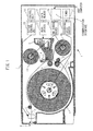
- FIG. 1 schematically illustrates the structure of a printer 1.
- FIG. 1 amongst the components provided in the printer 1, only those necessary for explanation are shown and the other components are not shown.
- the printer 1 (an example of the image forming device) is a printer which forms images of a plurality of colors such as yellow, magenta, and cyan, on the same sheet, by reciprocally moving a rolled recording paper (an example of the recording medium) with respect to a head, to thereby repeat a plurality of image forming processes on the recording paper.
- Image forming will also be referred to as "printing" hereinafter.
- the printer 1 forms an image on a recording surface of a rolled recording paper 10 which is held in a rolled paper holder 2 and which is unwound from the rolled paper holder 2.
- the rolled recording paper 10 is held by the rolled paper holder 2, for example, with the rotational shaft of the rolled recording paper 10 being rotatably supported by the rolled paper holder 2.
- the recording paper 10 is rotatably housed in the rolled paper holder 2.
- the image forming is performed by recording ink at a predetermined position by a head 3, while bringing an ink ribbon (an example of the transfer medium) into contact with the recording surface of the recording paper 10.
- the ink ribbon 4 and the recording paper 10 are superposed and moved to pass between the head 3 and a platen roller 9.
- the head 3 is configured to be movable with respect to the platen roller 9, and is pushed and pressed against the platen roller 9 when an image is formed.
- heating elements which constitute the head 3 generate heat in a predetermined pattern, so that an image is transferred from the ink ribbon 4 onto the recording paper 10 to thereby form an image on the recording paper 10.
- ink areas for yellow, magenta, and cyan which correspond to the colors of the image to be formed are prepared and arranged on the ink ribbon 4 sequentially in the winding direction of the ink ribbon 4, and the movement of the ink areas to pass the head 3 while winding the ink ribbon is repeated for each color.
- the ink ribbon 4 is fed from a feeding ribbon roller 4A and is wound around a winding ribbon roller 4B. These rollers may also be referred to as "ribbon rollers 4A, 4B" hereinafter.
- the ink ribbon 4 is guided by a ribbon guide roller 15 provided between the feeding ribbon roller 4A and the head 3, and a ribbon guide portion 16 (see FIG. 2A ) formed integrally with the head 3.
- the recording paper 10 When an image of each color is formed, the recording paper 10 is fed (unwound) by an amount corresponding to the length enough for the recording paper to pass the position of the head 3 for image forming, and is rewound thereafter.
- the head 3 forms the image in the process of rewinding the recording paper 10.
- the printer 1 reciprocally moves the recording paper 10 to form the images of respective colors superimposed on the same image forming area of the recording paper 10.
- the reciprocal movement of the recording paper 10 is performed by a grip roller 17 and a pinch roller 18 provided on a feeding path of the recording paper 10.
- the rotation direction of the rolled paper holder 2 is changed by these rollers in accordance with the feeding direction of the recording paper 10 to thereby repeat the unwinding and winding of the recording paper 10.
- the pinch roller 18 When the image forming is not performed, the pinch roller 18 is spaced from the grip roller 17 to release the recording paper 10. On the other hand, while an image is formed, the grip roller 17 and the pinch roller 18 hold and feed the recording paper 10 therebetween. Thus, the recording paper 10 is reciprocally moved with respect to the head 3, and a plurality of image forming processes on the same image forming area of the recording paper 10 are repeated.
- the ink ribbon 4 includes an overcoat layer (an example of the transfer materials) in addition to the ink areas for yellow, magenta, and cyan. After the images of all colors are formed on the recording surface of the recording paper 10, the recording surface is coated with and protected by the overcoat layer.
- an overcoat layer an example of the transfer materials
- the printer 1 also includes a recording paper cutter 5 located directly before a discharge outlet 6 and on a discharge path 13.
- the recording paper 10 having an image formed thereon passes the head 3, and is thereafter delivered through the discharge path 13 and discharged to the outside of the printer from the discharge outlet 6 provided for a housing 7 of the printer.
- the recording paper cutter 5 cuts the recording paper 10 discharged from the discharge outlet 6 at a position just before the discharge outlet 6. Consequently, the cut recording paper 10 is removed from the discharge outlet 6.
- the printer 1 further includes a control unit 30, a data memory 31, a recording paper driver 32, a head driver 33, an ink ribbon driver 34, a cutter control unit 35, and a communication interface 36.
- the control unit 30 generally controls the operations of the printer 1.
- the control unit 30 includes CPU, RAM, ROM, etc., and performs the image forming operation described later by loading and executing a program preliminarily stored in the ROM to the RAM.
- the data memory 31 forms a storage area to store image data received from a host computer via the communication interface 36.
- the recording paper driver 32 moves the recording paper 10 pinched between the grip roller 17 and the pinch roller 18.
- the recording paper driver 32 feeds the recording paper 10 by rotating the grip roller 17 and the rolled paper holder 2.
- the recording paper driver 32 rewinds the fed recording paper 10 by rotating the grip roller 17 and the rolled paper holder 2 in the reverse direction.
- the printer 1 forms an image on the recording paper 10 when the fed recording paper 10 is rewound.
- the head driver 33 drives the head 3 based on the image data to form an image on the recording paper.
- the head 3 can be of any type of mechanism depending on various image forming methods, such as a sublimation-type printer, a thermal-fusion-type printer, etc.
- the printer 1 is provided with the head 3, the platen roller 9, and the head driver 33, as an example of the image forming unit to form an image on a recording medium.
- the ink ribbon driver 34 drives the feeding ribbon roller 4A and the winding ribbon roller 4B to move the ink ribbon 4 with respect to the head 3, in synchronization with the operation of the head 3.
- the ink ribbon driver 34 also includes a rewinding mechanism of the ink ribbon 4, and is capable of driving the ink ribbon 4 in the rewinding direction, which is opposite to the winding direction (forward direction).
- the printer 1 is provided with the ribbon rollers 4A, 4B, and the ink ribbon driver 34, as an example of a feeding unit to feed a strip-shaped transfer medium.
- the cutter control unit 35 controls the recording paper cutter 5 so that the recording paper 10 is cut off at the rear end of the recorded portion when the recording paper 10 is discharged from the discharge outlet 6 via the discharge path 13.
- the communication interface 36 transmits and receives data to and from the host computer via a communication cable.
- a timer 37 measures an elapsed time so that when data for, for example, two images smaller than each ink area of the ink ribbon 4 is received successively from the host computer within a predetermined time, the data for the two images is allocated to the same ink area to form an image.
- FIGs. 2A and 2B are enlarged views of the surroundings of the head 3 in FIG. 1 .
- FIG. 2A illustrates the positional relationship between the head 3 and the recording paper 10 when the image forming for one color begins.
- FIG. 2B illustrates the positional relationship between the head 3 and the recording paper 10 when the image forming for one color ends.
- the position of the head 3 which is forming an image is shown by a solid line
- the position of the head 3 which is not forming an image is shown by a dashed line.
- the recording paper 10 is fed in the direction of an arrow A by an amount corresponding to the length of the image forming area on the recording paper 10, so that an edge 10E of the recording paper 10 is moved to the left side of the drawing.
- the image forming for yellow begins, the front end of the ink area of yellow and the front end of the image forming area on the recording paper 10 are registered with a position Ph where the head 3 forms an image.
- the position where the head 3 forms an image on the feeding path of the ink ribbon 4 will be referred to as the "head position Ph".
- the recording paper 10 is fed in the direction of the arrow A again.
- the positional relationship of the head 3 and the recording paper 10 is as shown in FIG. 2A again.
- the front end of the next ink area of magenta and the front end of the image forming area on the recording paper 10 are registered with the head position Ph, and the image forming for magenta is performed.
- images of yellow, magenta, cyan, and an overcoat are formed on the recording paper 10 which is moved reciprocally in the lateral direction of the drawing.
- the recording paper 10 is fed in the direction of the arrow A, is cut out by the recording paper cutter 5 at the rear end of the image, and is discharged.
- the ink ribbon 4 is fed in the direction of the arrow C when it is wound around the winding ribbon roller 4B, and fed in the direction of an arrow D when it is rewound by the feeding ribbon roller 4A.
- the directions of the arrows C and D respectively correspond to the winding and rewinding directions.
- the direction C in which the ink ribbon 4 moves from the feeding ribbon roller 4A toward the winding ribbon roller 4B, corresponds to the direction from the upstream to the downstream. This is opposite to the direction of the arrow A, in which the recording paper 10 is moved to pass through the head 3 and the platen roller 9 and is discharged via the discharge path 13.
- the printer 1 is provided with a ribbon sensor 8 for detecting a border between the ink areas of the ink ribbon 4 on which yellow ink, magenta ink, cyan ink and an overcoat are applied successively, on the downstream side of the head 3 in the winding direction of the ink ribbon 4.
- the ribbon sensor 8 is an example of a detection unit to detect a border between the transfer material areas.
- the ribbon sensor detects a border between an area and the subsequent area, when the printing of a corresponding color is completed and the ink ribbon 4 is further wound.
- the respective ink areas and the overcoat area (an example of the transfer material areas) will be referred to as a "panel", and a border between the panels will be referred to as a "panel border”.
- the position Ps (detection position) on the feeding path of the ink ribbon 4 where the ribbon sensor 8 is provided will be referred to as a "sensor position Ps".
- the ribbon sensor may be arranged in any position as long as it can detect panel borders.
- the ribbon sensor may be arranged on the upstream side of the head 3 in the winding direction of the ink ribbon 4.
- a transmission-type color sensor is used as the ribbon sensor 8.
- the transmission-type color sensor includes a transmitter-side ribbon sensor and a receiver-side ribbon sensor, which are provided on opposite sides of the feeding path of the ink ribbon 4 and are opposed to each other. The positions of the transmitter-side ribbon sensor and the receiver-side ribbon sensor may be replaced by one another.
- Either one or both of the ribbon rollers 4A and 4B include an encoder (or encoders) (not shown) which detects the displacement of the ink ribbon 4.
- the ink ribbon driver 34 calculates the amount of feeding necessary to align the front end of each panel with the head position Ph of the head 3, based on the pulse number of the encoder, the winding diameter of either one or both of the ribbon rollers 4A, 4B, and the detection result of the ribbon sensor 8, etc.
- the ink ribbon driver 34 feeds the ink ribbon 4 in accordance with the calculated amount of feeding, to align the front end of each panel with the head position Ph.
- the length of an image which can be formed on the recording paper 10 depends on the lengths of the respective color ink areas of the ink ribbon 4.
- the printer 1 uses the ink ribbon 4 having the length corresponding to L-size or 2L-size.
- the printer 1 can also form an image having a shorter length than the length corresponding to the ink ribbon 4. For example, if an ink ribbon for 2L-size is used, the printer can form an image of L-size, as well as the image of 2L-size.
- the printer 1 can print an image whose size is smaller than the size of each panel of the ink ribbon 4.
- an image whose size is, for example, 6 x 8 inches or one-half thereof, i.e., 6 x 4 inches (152 x 101 mm) is formed by using an ink ribbon 4 whose panel size is equal to 6 x 8 inches (152 x 203 mm).
- the sizes are not limited to the above, and the following example of operation can be applied to a pair of area sizes which differ from one another by more than two times.
- the pair of sizes may be A5 size (148 x 210 mm) and A6 size (105 x 148 mm), or 2L size (127 x 178 mm) and L-size (89 x 127 mm), etc.
- 6 x 8 size the size of 6 x 8 inches
- 6 x 4 size the size of 6 x 4 inches
- the 6 x 8 size is an example of the first size
- the 6 x 4 size is an example of the second size which is not more than one-half of the first size.
- the printer 1 stores, inside thereof, information indicating that there are half-unused panels, and determines whether or not the half-unused panels should be used for next printing, based on the data indicating the aforementioned information and the size of the image to be printed next. If the next image can be formed by using the half-unused panels, the printer 1 rewinds the ink ribbon by using the ink ribbon rewinding mechanism, and performs printing with the half-unused panels.
- the information indicating whether or not there are half-unused panels may be stored in the memory of the host computer from which image data is received, or may be stored based on the stop position of the ink ribbon 4.
- the ribbon sensor 8 detects the color of the panel located at the sensor position Ps when the ink ribbon 4 is stopped, and the control unit 30 judges whether or not there are half-unused panels in the ink ribbon 4, based on the detected panel color. For example, if the ribbon sensor 8 detects yellow when the ink ribbon 4 is stopped, the control unit 30 judges that there is no half-unused panel, and if the ribbon sensor 8 detects a color other than yellow (for example, cyan or magenta), the control unit 30 judges that there are half-unused panels.
- a color other than yellow for example, cyan or magenta
- control unit 30 judges whether or not the half-unused panels of the ink ribbon 4, if any, can be used to form the next image, based on the detection result of the ribbon sensor 8 and the size of the image to be printed next, received from the host computer.
- the ink ribbon driver 34 When the next image data is received, and the control unit 30 judges that the half-unused panels can be reused, the ink ribbon driver 34 rewinds the ink ribbon 4 by using the rewinding mechanism until the front end of the unused portion of the half-unused yellow panel reaches the head position Ph. The head 3 then forms the next image on the recording paper 10 by using the unused portion. On the other hand, if the control unit 30 judges that the half-unused panels cannot be reused, the ink ribbon driver 34 moves the ink ribbon to register the front end of a new yellow panel with the head position Ph. The head 3 then forms the next image on the recording paper 10 by using the new panels.
- the panel border between the used portion of a panel which has been used to form an image and whose ink has been exhausted and the unused portion of the next panel may be detected.
- the rear halves of panels in the winding direction (forward direction) of the ink ribbon 4 have been used in the previous image forming, and the front halves of the panels are to be used for forming a new image, it is necessary to detect the panel border between the used rear half of one panel and the unused front half of the next panel.
- the detection level by the ribbon sensor 8 is not stable when the used rear half passes through the sensor position Ps, thus, erroneous detection of the panel border at which the panels change from the used portion to the unused portion may occur.
- FIGs. 3A and 3B illustrate output waveforms of the ribbon sensor 8.
- the output waveforms are correlated with the position on the ink ribbon 4 corresponding to the respective output values.
- FIG. 3A shows an output waveform when the panels of unused overcoat OP0 and yellow Y1 pass the sensor position Ps.
- the output value significantly decreases at the panel border of overcoat OP0 and yellow Y1.
- the output value is substantially constant on the respective panels.
- FIG. 3B shows an output waveform when the panels of unused overcoat OP0 and partially used yellow Y1 pass the sensor position Ps.
- the panel of yellow Y1 although the front half Y1A in the winding direction is unused, the rear half Y1B has been used and the ink thereof has been partially exhausted.
- the output waveform of the ribbon sensor 8 for the partially used panel rises and falls as indicated by the arrows, depending on the printed image. Therefore, upon detecting the panel border between yellow Y1 and the subsequent magenta (not shown), the printer 1 may erroneously detect the rising or falling indicated by the arrows as being the panel border.
- the ribbon sensor 8 detects the panel border between the unused rear half of one panel and the used front half of the next panel. In this case, the panel border at which the panels change from the unused portion where ink remains to the new color is detected, and accordingly, the possibility of erroneous detection as described above is reduced.
- creases may be generated on the ink ribbon 4 when a new image is formed by using the rear halves of the panels. It is known that fewer creases are generated when the rear halves of panels are used first. Accordingly, when an image whose size is not more than one-half of the panel size is formed, it is preferable that the rear halves be used first, and it is necessary to prevent the aforementioned erroneous detection of the panel border.
- the ink ribbon driver 34 winds the ink ribbon 4 until the unused portion of a subsequent panel reaches the sensor position Ps, and thereafter, rewinds the ink ribbon 4.
- the ribbon sensor 8 detects the panel border in the rewinding process. That is, by feeding the ink ribbon 4 in the forward direction until the panel border passes the sensor position Ps, and thereafter feeding the ink ribbon in the reverse direction, the ribbon sensor 8 detects the panel border which approaches the sensor position Ps from the side where the ink remains. This makes erroneous detection of the panel border occur less frequently, since the detection level of the ribbon sensor 8 is substantially constant in the unused portion of the panel.
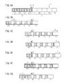
- FIGs. 4A to 5K are explanatory views showing the movement of the ink ribbon 4.
- FIG. 4A shows an ink ribbon 4 of a 6 x 8 size.
- the area 40 corresponds to the panels which have been entirely used, and the area 41 corresponds to the panels which have not been used at all.
- the area 40 includes the panels of yellow Y0, magenta M0, cyan C0, and overcoat OP0, and the area 41 includes the panels of yellow Y1, magenta M1, cyan C1, and overcoat OP1.
- Other panels (not shown) of yellow, magenta, cyan, and overcoat are repeatedly arranged on the areas on the left side of the area 40 and on the right side of the area 41 in this order.
- FIG. 4A illustrates a state in which the panels up to the area 40 have been entirely used and the panels of the area 41 are ready for printing.
- the front end of yellow Y1 is positioned at the head position Ph.
- FIG. 4B illustrates a state in which an image of 6 x 4 size has been formed in accordance with a print command from the host computer, by using the rear halves of the panels of the area 41 in the direction of the arrow C (forward direction, winding direction).
- the ink ribbon 4 is wound around the winding ribbon roller 4B by the ink ribbon driver 34, and is fed in the direction of the arrow C.
- the panels of the area 41 which were entirely unused before the printing, become half-unused panels, since the rear halves of the panels of 6 x 8 size in the winding direction have been used.
- FIG. 4C illustrates a state in which, when there are half-unused panels, data of a 6 x 4 size image is received from the host computer, and the ink ribbon 4 is rewound until the front half of yellow Y1 whose rear half has been used in the previous image forming reaches the sensor position Ps.
- the ink ribbon 4 is fed by the ink ribbon driver 34 in the direction of the arrow D (reverse direction, rewinding direction), toward the feeding ribbon roller 4A.
- FIG. 4D illustrates a state in which the panel border between overcoat OP0 and yellow Y1 is detected by the ribbon sensor 8, while the ink ribbon 4 is further rewound in the direction of the arrow D.
- the ribbon sensor 8 detects, at the sensor position Ps, the panel border at which the panels changes from the unused portion of yellow Y1 to overcoat OP0, and thus, the erroneous detection of the panel border occurs less frequently.
- FIG. 4E illustrates a state in which the ink ribbon 4 is further rewound in the direction of the arrow D, until the front end of yellow Y1 reaches the head position Ph.
- the ink ribbon 4 is further rewound by an amount corresponding to the distance between the sensor position Ps and the head position Ph, so that the printing starts at the front end of yellow Y1.
- FIG. 4F illustrates a state in which the printing is performed by using the front half of yellow Y1. During the printing, the ink ribbon 4 is wound in the direction of the arrow C.
- FIG. 4G illustrates a state in which the ink ribbon 4 is rewound in the direction of the arrow C until the unused front half of magenta M1 reaches the sensor position Ps, after the printing using yellow Y1 is performed.
- the ink ribbon 4 is wound in the direction of the arrow C until the unused portion of the next panel reaches the sensor position.
- FIG. 5H illustrates a state in which the panel border between yellow Y1 and magenta M1 is detected by the ribbon sensor 8, while the ink ribbon 4 is again rewound in the direction of the arrow D.
- the ribbon sensor 8 detects, at the sensor position Ps the panel border at which the panels changes from the unused portion of magenta M1 to yellow Y1, and thus, the erroneous detection of the panel border occurs less frequently.
- FIG. 5I illustrates a state in which the ink ribbon 4 is further rewound in the direction of the arrow D, until the front end of magenta M1 reaches the head position Ph.
- the ink ribbon 4 is further rewound by an amount corresponding to the distance between the sensor position Ps and the head position Ph, so that the printing starts at the front end of magenta M1.
- FIG. 5J illustrates a state in which the printing is performed by using the front half of magenta M1. During the printing, the ink ribbon 4 is wound in the direction of the arrow C.
- FIG. 5K illustrates a state in which the ink ribbon 4 is rewound in the direction of the arrow C until the unused front half of cyan C1 reaches the sensor position Ps, after the printing using magenta M1 is performed. Thereafter, the detection of the front end of cyan C1 (the panel border between magenta M1 and cyan C1) and the front end of overcoat OP1 (the panel border between cyan C1 and overcoat OP1) is performed in the same way as the detection of the front end of magenta M1 as shown in FIGs. 5H and 5I .
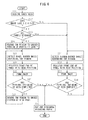
- FIG. 6 is a flow chart showing an example of the operation of the printer 1. The steps shown in FIG. 6 are executed by the CPU in the control unit 30, in accordance with a program preliminarily stored in the ROM in the control unit 30. Assume that an ink ribbon 4 of 6 x 8 size is set in the printer 1.
- the printer 1 receives a print command and image data of an image to be printed from the host computer (S11). Then, the control unit 30 judges whether or not the image data correspond to a 6 x 4 size image (S12). If the image data corresponds to, for example, a 6 x 8 size image, other than a 6 x 4 size image (No in S12), the process proceeds to S31, which will be discussed later, and the head 3 forms the image on the recording paper 10 by using the entirety of panels of 6 x 8 size. If the image data represents an image larger than the panels of 6 x 8 size, error processing is performed (not shown).
- the control unit 30 judges whether or not the panels used in the previous image forming can be reused, with reference to the information which indicates whether or not there are half-unused panels and which are retained in the printer (S13). If the control unit 30 judges that the panels cannot be reused (No in S13), the process proceeds to S31, which will be discussed later, and the head 3 forms the image of 6 x 4 size on the recording paper 10 by using the new panels.
- the ink ribbon driver 34 rewinds the ink ribbon 4 until the unused front half of the panel of yellow Y reaches the sensor position Ps, as shown in FIG. 4C (S20).
- the ink ribbon driver 34 calculates the necessary amount of feeding based on the pitch of the panels, the pulse number of the encoder, the winding diameters of the ribbon rollers 4A, 4B, etc., and rewinds the ink ribbon 4 in the direction of the arrow D in accordance with the calculated amount of feeding.
- the ribbon sensor 8 detects the panel border (initially, the panel border between overcoat OP and yellow Y), while the ink ribbon driver 34 further rewinds the ink ribbon 4 in the direction of the arrow D (S21).
- the ink ribbon driver 34 further feeds the ink ribbon 4 by an amount corresponding to the distance between the sensor position Ps and the head position Ph, until the front end of yellow Y reaches the head position Ph (S22). Since the ribbon sensor 8 is provided on the downstream side of the head 3 in the winding direction in the printer 1, the ink ribbon 4 is rewound in the direction of the arrow D. If the ribbon sensor 8 is provided on the upstream side of the head 3 in the winding direction, the ink ribbon 4 is wound in the direction of the arrow C.
- the head 3 forms an image as shown in FIG. 4F by using one panel (yellow Y at first) (S23).
- the recording paper driver 32 feeds the recording paper 10 in accordance with the size of the image forming area on the recording paper 10.
- the head driver 33 moves the head 3 to press the head against the platen roller 9.
- the recording paper driver 32 rewinds the recording paper 10
- the head 3 forms an image of one color (yellow Y at first).
- the ink ribbon driver 34 moves the ink ribbon 4. The rewinding of the recording paper 10, the winding of the ink ribbon 4, and the image forming by the head 3 are synchronously performed.
- the head driver 33 moves the head 3 away from the platen roller 9.
- the control unit 30 judges whether or not the printing including overcoat OP is completed (S24). If the printing including overcoat OP has not been completed yet (No in S24), the ink ribbon driver 34 winds the ink ribbon 4 until the unused front half of the panel of the next color (the second is magenta M) reaches the sensor position Ps, as shown in FIG. 4G (S25).
- the process then returns to S21, and the panel border detection and the image forming are performed for magenta M, cyan C, and overcoat OP, in the same way as yellow Y.
- the printer 1 forms respective color images of yellow Y, magenta M, and cyan C on the same image forming area of the recording paper 10, and applies the overcoat layer to form a protection layer.
- the process proceeds to S40.
- the ink ribbon driver 34 moves the ink ribbon 4 to register the front end of the subsequent yellow Y with the sensor position Ps and stops the ink ribbon at the registered position.
- the image forming is performed by using new panels. This corresponds to the case where the next image is too large to be formed in the unused portions (in this example, 6 x 8 size), or the case where there is no half-unused panel although the size of the image fits the unused portions.
- the ribbon sensor 8 detects the panel border (the panel border between overcoat OP and yellow Y, at first) (S31). If the front end of yellow is originally positioned at the sensor position Ps, no movement of the ink ribbon occurs.
- the ink ribbon driver 34 feeds the ink ribbon 4 by an amount corresponding to the distance between the sensor position Ps and the head position Ph until the front end of yellow Y reaches the head position Ph (S32). After the position of the front end of the panel is aligned as described above, the head 3 forms an image by using one panel in the same way as in S23 (S33). Thereafter, the control unit 30 judges whether or not the printing including overcoat OP is completed (S34). If the printing including overcoat OP has not been completed yet (No in S34), the process returns to S31, and if the printing including overcoat OP has been completed (Yes in S34), the process proceeds to S40.
- the control unit 30 stores this information in the printer 1.
- the ink ribbon driver 34 may rewind the ink ribbon 4 until the panel of, for example, cyan reaches the sensor position Ps, and stop the ink ribbon 4 at a different position from the usual stop position when the printing has been completed.
- the recording paper 10 is fed by the recording paper driver 32, cut by the recording paper cutter 5, and discharged from the discharge outlet 6 (S40).
- the operation of the printer 1 ends.
- the printer 1 when unused portions of the partially used ink ribbon 4 are used for printing, by feeding the ink ribbon 4 in the forward direction until an unused portion of a subsequent panel adjacent to a used portion of one panel reaches the sensor position Ps, and thereafter feeding the ink ribbon in the reverse direction, the ribbon sensor 8 detects the panel border between the used portion and the unused portion, the panel border approaching the sensor position Ps from the side where the ink remains. With such a detection method, in the printer 1, erroneous detection of the panel border occurs less frequently.
Landscapes
- Physics & Mathematics (AREA)
- Electromagnetism (AREA)
- Electronic Switches (AREA)
- Impression-Transfer Materials And Handling Thereof (AREA)
Abstract
Description
- This invention relates to an image forming device and an image forming method.
- An image forming device is known which forms an image on a recording medium by transferring transfer materials respectively for a plurality of transfer material areas repeatedly arranged in the longitudinal direction of a strip-shaped transfer medium. Specifically, an image forming device is known which partially uses the transfer material areas to form an image having a size not more than one-half of a transfer material area, and thereafter rewinds the transfer medium, and then uses unused portions of the partially used transfer material areas to form a new image having the same size.
-
Patent Literature 1 describes a thermal transfer color printer which uses, when performing L-size printing by using an ink ribbon corresponding to 2L-size, the rear part of each ink area of the ink ribbon (rewinding direction of the ink ribbon) prior to the front part (winding direction of the ink ribbon) thereof which is normally considered to be used prior to the rear part. With this printer, if L-size printing is performed in two steps, when the ink ribbon which has been used to print the first sheet is rewound and reused, the second sheet can be printed without being affected by creases formed in the portion of the ink ribbon where the ink has been exhausted. -
Patent Literature 2 describes a thermal transfer recording device for transfer-recording an image on a recording sheet by using an ink sheet corresponding to an A4 size recording sheet and including dye portions for different colors. This thermal transfer recording device includes a counter to count the number of recorded sheets up to the present time in an A5 size recording mode, and in the case of a continual recording on a A5 size recording sheet, when the number of the sheets counted by the counter is an odd number, the transfer recording of each color is conducted in the same way as A4 size recording, and when the number of the sheets counted by the counter is an even number, the transfer recording of each color is conducted while the ink sheet is rewound by driving a rewinding motor. -
Patent Literature 3 describes a transfer method in a recording device which superimposes and transfers different color inks onto a recording sheet from an ink sheet having a plurality of color inks successively applied thereon in the feeding direction. With this transfer method, if an image is transferred onto a recording sheet whose surface area is approximately one-half of each surface area of the ink sheet that has been coated with an ink, front halves of respective color ink-applied areas are used to transfer an image, thereafter, the ink sheet is rewound to a portion where the rear halves of the ink-applied areas can be transferred, and another image is transferred by using the rear halves of the ink sheet. - A transfer medium provided with a marking such as a black borderline which is used to detect a border between transfer material areas is known. However, transfer media without such markings are more commonly used, in order to provide as large transfer material areas as possible. In response to such transfer media, an image forming device is provided with a detection unit which detects the border between the transfer material areas based on a change of the colors of the transfer material areas that are fed and pass the detection position.
-
- Patent Literature 1: Japanese Patent Application Laid-open Publication No.
2004-202941 - Patent Literature 2: Japanese Patent Application Laid-open Publication No.
H06-143720 - Patent Literature 3: Japanese Patent Application Laid-open Publication No.
H04-148944 - When a new image is formed by using unused portions of partially used transfer material areas, a border between the used portion of one transfer material area and the unused portion of the subsequent transfer material area may be detected. However, if a border between the used portion in which the transfer material has been exhausted in the previous image forming and the unused portion on which the transfer material remains is detected by a detection unit which detects the border between the transfer material areas based on the color change between the transfer material areas, erroneous detection may occur due to the unstable detection level.
- Therefore, an object of the present invention is to reduce the possibility of erroneous detection of a border between transfer material areas when forming a new image by using unused portions of partially used transfer material areas, compared with a device which does not have the constituent features of the present invention.
- Provided is an image forming device including a feeding unit to feed a strip-shaped transfer medium on which a plurality of transfer material areas each having a first size and respectively corresponding to a plurality of transfer materials are repeatedly arranged in a predetermined sequence in the longitudinal direction of the transfer medium, an image forming unit to form an image having the first size or a second size which is not more than one-half of the first size on a recording medium by transferring the transfer materials respectively for the transfer material areas, a detection unit to detect a border between the transfer material areas based on a change of colors of the transfer material areas which are fed by the feeding unit and pass through a detection position, and a control unit to control the feeding unit to feed the transfer medium in a forward direction until an unused portion of a subsequent transfer material area adjacent to a used portion of a transfer material area reaches the detection position and thereafter to feed the transfer medium in the reverse direction, so that the detection unit detects the border between the used portion and the unused portion from the unused portion side, when an image of the second size is newly formed by the image forming unit by using unused portions included in the respective transfer material areas which have been used to form an image of the second size.
- Preferably, in the image forming device, when an image of the second size is formed by using unused transfer material areas, the image forming unit uses rear halves of the respective transfer material areas in the forward direction, and the used portion is the rear half of the transfer material area in the forward direction, and the unused portion is the front half of the transfer material area in the forward direction.
- Additionally, provided is an image forming method to form an image having a first size or a second size which is not more than one-half of the first size on a recording medium by transferring a plurality of transfer materials respectively for a plurality of transfer material areas, while feeding a strip-shaped transfer medium on which the transfer material areas each having the first size and respectively corresponding to the transfer materials are repeatedly arranged in a predetermined sequence in the longitudinal direction of the transfer medium. The method includes the steps of detecting a border between the transfer material areas based on a change of colors of the transfer material areas which are fed and pass through a detection position, and controlling the transfer medium to be fed in a forward direction until an unused portion of a subsequent transfer material area adjacent to a used portion of a transfer material area reaches the detection position and thereafter fed in the reverse direction, so that the border between the used portion and the unused portion is detected from the unused portion side, when an image of the second size is newly formed by using unused portions included in the respective transfer material areas which have been used to form an image of the second size.
- The above image forming device and image forming method can reduce the possibility of erroneous detection of a border between transfer material areas when forming a new image by using unused portions of partially used transfer material areas, compared with a device which does not have the constituent features of the present invention.
-
-
FIG. 1 schematically illustrates the structure of aprinter 1; -
FIGs. 2A and 2B are enlarged views of the surroundings of thehead 3 inFIG. 1 ; -
FIGs. 3A and 3B illustrate output waveforms of theribbon sensor 8; -
FIGs. 4A to 4G are explanatory views showing the movement of theink ribbon 4; -
FIGs. 5H to 5K are explanatory views showing the movement of theink ribbon 4; and -
FIG. 6 is a flow chart showing an example of the - Hereinafter, with reference to the accompanying drawings, an image forming device and an image forming method will be explained in detail. However, it should be noted that the technical scope of the present invention is not limited to embodiments thereof and includes the invention described in claims and equivalents thereof.
-
FIG. 1 schematically illustrates the structure of aprinter 1. InFIG. 1 , amongst the components provided in theprinter 1, only those necessary for explanation are shown and the other components are not shown. - The printer 1 (an example of the image forming device) is a printer which forms images of a plurality of colors such as yellow, magenta, and cyan, on the same sheet, by reciprocally moving a rolled recording paper (an example of the recording medium) with respect to a head, to thereby repeat a plurality of image forming processes on the recording paper. Image forming will also be referred to as "printing" hereinafter.
- The
printer 1 forms an image on a recording surface of a rolledrecording paper 10 which is held in a rolledpaper holder 2 and which is unwound from the rolledpaper holder 2. The rolledrecording paper 10 is held by the rolledpaper holder 2, for example, with the rotational shaft of the rolledrecording paper 10 being rotatably supported by the rolledpaper holder 2. Thus, therecording paper 10 is rotatably housed in the rolledpaper holder 2. - The image forming is performed by recording ink at a predetermined position by a
head 3, while bringing an ink ribbon (an example of the transfer medium) into contact with the recording surface of therecording paper 10. During the recording process, theink ribbon 4 and therecording paper 10 are superposed and moved to pass between thehead 3 and aplaten roller 9. Thehead 3 is configured to be movable with respect to theplaten roller 9, and is pushed and pressed against theplaten roller 9 when an image is formed. In theprinter 1, heating elements which constitute thehead 3 generate heat in a predetermined pattern, so that an image is transferred from theink ribbon 4 onto therecording paper 10 to thereby form an image on therecording paper 10. - To form a colored image, ink areas for yellow, magenta, and cyan (examples of the transfer materials) which correspond to the colors of the image to be formed are prepared and arranged on the
ink ribbon 4 sequentially in the winding direction of theink ribbon 4, and the movement of the ink areas to pass thehead 3 while winding the ink ribbon is repeated for each color. Theink ribbon 4 is fed from afeeding ribbon roller 4A and is wound around a windingribbon roller 4B. These rollers may also be referred to as "ribbon rollers ink ribbon 4 is guided by aribbon guide roller 15 provided between thefeeding ribbon roller 4A and thehead 3, and a ribbon guide portion 16 (seeFIG. 2A ) formed integrally with thehead 3. - When an image of each color is formed, the
recording paper 10 is fed (unwound) by an amount corresponding to the length enough for the recording paper to pass the position of thehead 3 for image forming, and is rewound thereafter. Thehead 3 forms the image in the process of rewinding therecording paper 10. During the image forming process, theprinter 1 reciprocally moves therecording paper 10 to form the images of respective colors superimposed on the same image forming area of therecording paper 10. The reciprocal movement of therecording paper 10 is performed by agrip roller 17 and apinch roller 18 provided on a feeding path of therecording paper 10. The rotation direction of the rolledpaper holder 2 is changed by these rollers in accordance with the feeding direction of therecording paper 10 to thereby repeat the unwinding and winding of therecording paper 10. When the image forming is not performed, thepinch roller 18 is spaced from thegrip roller 17 to release therecording paper 10. On the other hand, while an image is formed, thegrip roller 17 and thepinch roller 18 hold and feed therecording paper 10 therebetween. Thus, therecording paper 10 is reciprocally moved with respect to thehead 3, and a plurality of image forming processes on the same image forming area of therecording paper 10 are repeated. - The
ink ribbon 4 includes an overcoat layer (an example of the transfer materials) in addition to the ink areas for yellow, magenta, and cyan. After the images of all colors are formed on the recording surface of therecording paper 10, the recording surface is coated with and protected by the overcoat layer. - The
printer 1 also includes arecording paper cutter 5 located directly before adischarge outlet 6 and on adischarge path 13. Therecording paper 10 having an image formed thereon passes thehead 3, and is thereafter delivered through thedischarge path 13 and discharged to the outside of the printer from thedischarge outlet 6 provided for ahousing 7 of the printer. Therecording paper cutter 5 cuts therecording paper 10 discharged from thedischarge outlet 6 at a position just before thedischarge outlet 6. Consequently, thecut recording paper 10 is removed from thedischarge outlet 6. - The
printer 1 further includes acontrol unit 30, adata memory 31, arecording paper driver 32, ahead driver 33, anink ribbon driver 34, acutter control unit 35, and acommunication interface 36. - The
control unit 30 generally controls the operations of theprinter 1. Thecontrol unit 30 includes CPU, RAM, ROM, etc., and performs the image forming operation described later by loading and executing a program preliminarily stored in the ROM to the RAM. Thedata memory 31 forms a storage area to store image data received from a host computer via thecommunication interface 36. - The
recording paper driver 32 moves therecording paper 10 pinched between thegrip roller 17 and thepinch roller 18. Therecording paper driver 32 feeds therecording paper 10 by rotating thegrip roller 17 and the rolledpaper holder 2. Moreover, therecording paper driver 32 rewinds the fedrecording paper 10 by rotating thegrip roller 17 and the rolledpaper holder 2 in the reverse direction. Theprinter 1 forms an image on therecording paper 10 when the fedrecording paper 10 is rewound. - The
head driver 33 drives thehead 3 based on the image data to form an image on the recording paper. Thehead 3 can be of any type of mechanism depending on various image forming methods, such as a sublimation-type printer, a thermal-fusion-type printer, etc. Theprinter 1 is provided with thehead 3, theplaten roller 9, and thehead driver 33, as an example of the image forming unit to form an image on a recording medium. - The
ink ribbon driver 34 drives the feedingribbon roller 4A and the windingribbon roller 4B to move theink ribbon 4 with respect to thehead 3, in synchronization with the operation of thehead 3. Theink ribbon driver 34 also includes a rewinding mechanism of theink ribbon 4, and is capable of driving theink ribbon 4 in the rewinding direction, which is opposite to the winding direction (forward direction). Theprinter 1 is provided with theribbon rollers ink ribbon driver 34, as an example of a feeding unit to feed a strip-shaped transfer medium. - The
cutter control unit 35 controls therecording paper cutter 5 so that therecording paper 10 is cut off at the rear end of the recorded portion when therecording paper 10 is discharged from thedischarge outlet 6 via thedischarge path 13. - The
communication interface 36 transmits and receives data to and from the host computer via a communication cable. Atimer 37 measures an elapsed time so that when data for, for example, two images smaller than each ink area of theink ribbon 4 is received successively from the host computer within a predetermined time, the data for the two images is allocated to the same ink area to form an image. -
FIGs. 2A and 2B are enlarged views of the surroundings of thehead 3 inFIG. 1 .FIG. 2A illustrates the positional relationship between thehead 3 and therecording paper 10 when the image forming for one color begins. On the other hand,FIG. 2B illustrates the positional relationship between thehead 3 and therecording paper 10 when the image forming for one color ends. InFIG. 2A , the position of thehead 3 which is forming an image is shown by a solid line, and the position of thehead 3 which is not forming an image is shown by a dashed line. - As shown in
FIG. 2A , when the image forming for one color begins, first, therecording paper 10 is fed in the direction of an arrow A by an amount corresponding to the length of the image forming area on therecording paper 10, so that anedge 10E of therecording paper 10 is moved to the left side of the drawing. For example, When the image forming for yellow begins, the front end of the ink area of yellow and the front end of the image forming area on therecording paper 10 are registered with a position Ph where thehead 3 forms an image. Hereinafter, the position where thehead 3 forms an image on the feeding path of theink ribbon 4 will be referred to as the "head position Ph". With theink ribbon 4 and therecording paper 10 superposed at the head position Ph, while therecording paper 10 and theink ribbon 4 are moved in the directions of arrows B and C, respectively, an image of yellow is formed on therecording paper 10 by thehead 3. - When the image forming for yellow is completed, as shown in
FIG. 2B , therecording paper 10 is fed in the direction of the arrow A again. As a result, the positional relationship of thehead 3 and therecording paper 10 is as shown inFIG. 2A again. Then, the front end of the next ink area of magenta and the front end of the image forming area on therecording paper 10 are registered with the head position Ph, and the image forming for magenta is performed. As may be understood from the foregoing, images of yellow, magenta, cyan, and an overcoat are formed on therecording paper 10 which is moved reciprocally in the lateral direction of the drawing. Thereafter, therecording paper 10 is fed in the direction of the arrow A, is cut out by therecording paper cutter 5 at the rear end of the image, and is discharged. - The
ink ribbon 4 is fed in the direction of the arrow C when it is wound around the windingribbon roller 4B, and fed in the direction of an arrow D when it is rewound by the feedingribbon roller 4A. The directions of the arrows C and D respectively correspond to the winding and rewinding directions. Regarding theink ribbon 4, the direction C, in which theink ribbon 4 moves from the feedingribbon roller 4A toward the windingribbon roller 4B, corresponds to the direction from the upstream to the downstream. This is opposite to the direction of the arrow A, in which therecording paper 10 is moved to pass through thehead 3 and theplaten roller 9 and is discharged via thedischarge path 13. - The
printer 1 is provided with aribbon sensor 8 for detecting a border between the ink areas of theink ribbon 4 on which yellow ink, magenta ink, cyan ink and an overcoat are applied successively, on the downstream side of thehead 3 in the winding direction of theink ribbon 4. Theribbon sensor 8 is an example of a detection unit to detect a border between the transfer material areas. The ribbon sensor detects a border between an area and the subsequent area, when the printing of a corresponding color is completed and theink ribbon 4 is further wound. Hereinafter, the respective ink areas and the overcoat area (an example of the transfer material areas) will be referred to as a "panel", and a border between the panels will be referred to as a "panel border". Further, the position Ps (detection position) on the feeding path of theink ribbon 4 where theribbon sensor 8 is provided will be referred to as a "sensor position Ps". - The ribbon sensor may be arranged in any position as long as it can detect panel borders. For example, the ribbon sensor may be arranged on the upstream side of the
head 3 in the winding direction of theink ribbon 4. - In the
printer 1, a transmission-type color sensor is used as theribbon sensor 8. The transmission-type color sensor includes a transmitter-side ribbon sensor and a receiver-side ribbon sensor, which are provided on opposite sides of the feeding path of theink ribbon 4 and are opposed to each other. The positions of the transmitter-side ribbon sensor and the receiver-side ribbon sensor may be replaced by one another. - Either one or both of the
ribbon rollers ink ribbon 4. Theink ribbon driver 34 calculates the amount of feeding necessary to align the front end of each panel with the head position Ph of thehead 3, based on the pulse number of the encoder, the winding diameter of either one or both of theribbon rollers ribbon sensor 8, etc. Theink ribbon driver 34 feeds theink ribbon 4 in accordance with the calculated amount of feeding, to align the front end of each panel with the head position Ph. - The length of an image which can be formed on the
recording paper 10 depends on the lengths of the respective color ink areas of theink ribbon 4. When an image corresponding to a photograph of, for example, L-size (89 x 127 mm) or 2L-size (127 x 178 mm) is formed, theprinter 1 uses theink ribbon 4 having the length corresponding to L-size or 2L-size. However, theprinter 1 can also form an image having a shorter length than the length corresponding to theink ribbon 4. For example, if an ink ribbon for 2L-size is used, the printer can form an image of L-size, as well as the image of 2L-size. - As mentioned above, the
printer 1 can print an image whose size is smaller than the size of each panel of theink ribbon 4. In the following discussion, it is assumed that an image whose size is, for example, 6 x 8 inches or one-half thereof, i.e., 6 x 4 inches (152 x 101 mm) is formed by using anink ribbon 4 whose panel size is equal to 6 x 8 inches (152 x 203 mm). However, the sizes are not limited to the above, and the following example of operation can be applied to a pair of area sizes which differ from one another by more than two times. For example, the pair of sizes may be A5 size (148 x 210 mm) and A6 size (105 x 148 mm), or 2L size (127 x 178 mm) and L-size (89 x 127 mm), etc. Hereinafter, the size of 6 x 8 inches will be referred to as "6 x 8 size", and the size of 6 x 4 inches will be referred to as "6 x 4 size". The 6 x 8 size is an example of the first size, and the 6 x 4 size is an example of the second size which is not more than one-half of the first size. - An example of the operation of the
printer 1 will be discussed below. When an image whose size is not more than one-half of the size of each panel has been formed, theprinter 1 stores, inside thereof, information indicating that there are half-unused panels, and determines whether or not the half-unused panels should be used for next printing, based on the data indicating the aforementioned information and the size of the image to be printed next. If the next image can be formed by using the half-unused panels, theprinter 1 rewinds the ink ribbon by using the ink ribbon rewinding mechanism, and performs printing with the half-unused panels. - The information indicating whether or not there are half-unused panels may be stored in the memory of the host computer from which image data is received, or may be stored based on the stop position of the
ink ribbon 4. In the latter case, theribbon sensor 8 detects the color of the panel located at the sensor position Ps when theink ribbon 4 is stopped, and thecontrol unit 30 judges whether or not there are half-unused panels in theink ribbon 4, based on the detected panel color. For example, if theribbon sensor 8 detects yellow when theink ribbon 4 is stopped, thecontrol unit 30 judges that there is no half-unused panel, and if theribbon sensor 8 detects a color other than yellow (for example, cyan or magenta), thecontrol unit 30 judges that there are half-unused panels. - Further, the
control unit 30 judges whether or not the half-unused panels of theink ribbon 4, if any, can be used to form the next image, based on the detection result of theribbon sensor 8 and the size of the image to be printed next, received from the host computer. - When the next image data is received, and the
control unit 30 judges that the half-unused panels can be reused, theink ribbon driver 34 rewinds theink ribbon 4 by using the rewinding mechanism until the front end of the unused portion of the half-unused yellow panel reaches the head position Ph. Thehead 3 then forms the next image on therecording paper 10 by using the unused portion. On the other hand, if thecontrol unit 30 judges that the half-unused panels cannot be reused, theink ribbon driver 34 moves the ink ribbon to register the front end of a new yellow panel with the head position Ph. Thehead 3 then forms the next image on therecording paper 10 by using the new panels. - When a subsequent image is formed by reusing half-unused panels, the panel border between the used portion of a panel which has been used to form an image and whose ink has been exhausted and the unused portion of the next panel may be detected. For example, if the rear halves of panels in the winding direction (forward direction) of the
ink ribbon 4 have been used in the previous image forming, and the front halves of the panels are to be used for forming a new image, it is necessary to detect the panel border between the used rear half of one panel and the unused front half of the next panel. However, in such a case, the detection level by theribbon sensor 8 is not stable when the used rear half passes through the sensor position Ps, thus, erroneous detection of the panel border at which the panels change from the used portion to the unused portion may occur. -
FIGs. 3A and 3B illustrate output waveforms of theribbon sensor 8. In the respective figures, the output waveforms are correlated with the position on theink ribbon 4 corresponding to the respective output values. -
FIG. 3A shows an output waveform when the panels of unused overcoat OP0 and yellow Y1 pass the sensor position Ps. The output value significantly decreases at the panel border of overcoat OP0 and yellow Y1. However, the output value is substantially constant on the respective panels. - On the other hand,
FIG. 3B shows an output waveform when the panels of unused overcoat OP0 and partially used yellow Y1 pass the sensor position Ps. In the panel of yellow Y1, although the front half Y1A in the winding direction is unused, the rear half Y1B has been used and the ink thereof has been partially exhausted. The output waveform of theribbon sensor 8 for the partially used panel rises and falls as indicated by the arrows, depending on the printed image. Therefore, upon detecting the panel border between yellow Y1 and the subsequent magenta (not shown), theprinter 1 may erroneously detect the rising or falling indicated by the arrows as being the panel border. - Contrary to the above, if the front halves of panels in the winding direction (forward direction) of the
ink ribbon 4 have been used in the previous image forming, and the rear halve of the panels are to be used for forming a new image, theribbon sensor 8 detects the panel border between the unused rear half of one panel and the used front half of the next panel. In this case, the panel border at which the panels change from the unused portion where ink remains to the new color is detected, and accordingly, the possibility of erroneous detection as described above is reduced. - However, if the front halves of panels in the winding direction of the
ink ribbon 4 are used first, creases may be generated on theink ribbon 4 when a new image is formed by using the rear halves of the panels. It is known that fewer creases are generated when the rear halves of panels are used first. Accordingly, when an image whose size is not more than one-half of the panel size is formed, it is preferable that the rear halves be used first, and it is necessary to prevent the aforementioned erroneous detection of the panel border. - To this end, in the
printer 1, if printing an image by using unused portions of the partially usedink ribbon 4, in detecting the panel border, theink ribbon driver 34 winds theink ribbon 4 until the unused portion of a subsequent panel reaches the sensor position Ps, and thereafter, rewinds theink ribbon 4. Theribbon sensor 8 detects the panel border in the rewinding process. That is, by feeding theink ribbon 4 in the forward direction until the panel border passes the sensor position Ps, and thereafter feeding the ink ribbon in the reverse direction, theribbon sensor 8 detects the panel border which approaches the sensor position Ps from the side where the ink remains. This makes erroneous detection of the panel border occur less frequently, since the detection level of theribbon sensor 8 is substantially constant in the unused portion of the panel. -
FIGs. 4A to 5K are explanatory views showing the movement of theink ribbon 4.FIG. 4A shows anink ribbon 4 of a 6 x 8 size. Thearea 40 corresponds to the panels which have been entirely used, and thearea 41 corresponds to the panels which have not been used at all. Thearea 40 includes the panels of yellow Y0, magenta M0, cyan C0, and overcoat OP0, and thearea 41 includes the panels of yellow Y1, magenta M1, cyan C1, and overcoat OP1. Other panels (not shown) of yellow, magenta, cyan, and overcoat are repeatedly arranged on the areas on the left side of thearea 40 and on the right side of thearea 41 in this order.FIG. 4A illustrates a state in which the panels up to thearea 40 have been entirely used and the panels of thearea 41 are ready for printing. The front end of yellow Y1 is positioned at the head position Ph. -
FIG. 4B illustrates a state in which an image of 6 x 4 size has been formed in accordance with a print command from the host computer, by using the rear halves of the panels of thearea 41 in the direction of the arrow C (forward direction, winding direction). Upon printing, theink ribbon 4 is wound around the windingribbon roller 4B by theink ribbon driver 34, and is fed in the direction of the arrow C. The panels of thearea 41 which were entirely unused before the printing, become half-unused panels, since the rear halves of the panels of 6 x 8 size in the winding direction have been used. -
FIG. 4C illustrates a state in which, when there are half-unused panels, data of a 6 x 4 size image is received from the host computer, and theink ribbon 4 is rewound until the front half of yellow Y1 whose rear half has been used in the previous image forming reaches the sensor position Ps. In this state, theink ribbon 4 is fed by theink ribbon driver 34 in the direction of the arrow D (reverse direction, rewinding direction), toward the feedingribbon roller 4A. -
FIG. 4D illustrates a state in which the panel border between overcoat OP0 and yellow Y1 is detected by theribbon sensor 8, while theink ribbon 4 is further rewound in the direction of the arrow D. In this state, theribbon sensor 8 detects, at the sensor position Ps, the panel border at which the panels changes from the unused portion of yellow Y1 to overcoat OP0, and thus, the erroneous detection of the panel border occurs less frequently. -
FIG. 4E illustrates a state in which theink ribbon 4 is further rewound in the direction of the arrow D, until the front end of yellow Y1 reaches the head position Ph. When the panel border between overcoat OP0 and yellow Y1 is detected, theink ribbon 4 is further rewound by an amount corresponding to the distance between the sensor position Ps and the head position Ph, so that the printing starts at the front end of yellow Y1. -
FIG. 4F illustrates a state in which the printing is performed by using the front half of yellow Y1. During the printing, theink ribbon 4 is wound in the direction of the arrow C. -
FIG. 4G illustrates a state in which theink ribbon 4 is rewound in the direction of the arrow C until the unused front half of magenta M1 reaches the sensor position Ps, after the printing using yellow Y1 is performed. As may be seen from the foregoing, when the printing using one panel is completed, theink ribbon 4 is wound in the direction of the arrow C until the unused portion of the next panel reaches the sensor position. -
FIG. 5H illustrates a state in which the panel border between yellow Y1 and magenta M1 is detected by theribbon sensor 8, while theink ribbon 4 is again rewound in the direction of the arrow D. In this state, theribbon sensor 8 detects, at the sensor position Ps the panel border at which the panels changes from the unused portion of magenta M1 to yellow Y1, and thus, the erroneous detection of the panel border occurs less frequently. -
FIG. 5I illustrates a state in which theink ribbon 4 is further rewound in the direction of the arrow D, until the front end of magenta M1 reaches the head position Ph. When the panel border between yellow Y1 and magenta M1 is detected, theink ribbon 4 is further rewound by an amount corresponding to the distance between the sensor position Ps and the head position Ph, so that the printing starts at the front end of magenta M1. -
FIG. 5J illustrates a state in which the printing is performed by using the front half of magenta M1. During the printing, theink ribbon 4 is wound in the direction of the arrow C. -
FIG. 5K illustrates a state in which theink ribbon 4 is rewound in the direction of the arrow C until the unused front half of cyan C1 reaches the sensor position Ps, after the printing using magenta M1 is performed. Thereafter, the detection of the front end of cyan C1 (the panel border between magenta M1 and cyan C1) and the front end of overcoat OP1 (the panel border between cyan C1 and overcoat OP1) is performed in the same way as the detection of the front end of magenta M1 as shown inFIGs. 5H and 5I . - When next printing for 6 x 8 size or 6 x 4 size is performed after overcoat OP1 is printed, thus resulting in the completion of the 6 x 4 size printing, the front end of yellow Y2 (the panel border between overcoat OP1 and yellow Y2) is successively detected. This detection may be performed in the same way as the detection of the front end of magenta M1 as shown in
FIGs. 5H and 5I , since the rear half of overcoat OP1 has been used and the front half of yellow Y2 remains unused. -
FIG. 6 is a flow chart showing an example of the operation of theprinter 1. The steps shown inFIG. 6 are executed by the CPU in thecontrol unit 30, in accordance with a program preliminarily stored in the ROM in thecontrol unit 30. Assume that anink ribbon 4 of 6 x 8 size is set in theprinter 1. - First, the
printer 1 receives a print command and image data of an image to be printed from the host computer (S11). Then, thecontrol unit 30 judges whether or not the image data correspond to a 6 x 4 size image (S12). If the image data corresponds to, for example, a 6 x 8 size image, other than a 6 x 4 size image (No in S12), the process proceeds to S31, which will be discussed later, and thehead 3 forms the image on therecording paper 10 by using the entirety of panels of 6 x 8 size. If the image data represents an image larger than the panels of 6 x 8 size, error processing is performed (not shown). - If the image data corresponds to a 6 x 4 size image (Yes in S12), the
control unit 30 judges whether or not the panels used in the previous image forming can be reused, with reference to the information which indicates whether or not there are half-unused panels and which are retained in the printer (S13). If thecontrol unit 30 judges that the panels cannot be reused (No in S13), the process proceeds to S31, which will be discussed later, and thehead 3 forms the image of 6 x 4 size on therecording paper 10 by using the new panels. - On the other hand, if the
control unit 30 judges that the panels can be reused (Yes in S13), since there are panels whose front halves in the winding direction have not been used as shown inFIG. 4B , theink ribbon driver 34 rewinds theink ribbon 4 until the unused front half of the panel of yellow Y reaches the sensor position Ps, as shown inFIG. 4C (S20). For this purpose, theink ribbon driver 34 calculates the necessary amount of feeding based on the pitch of the panels, the pulse number of the encoder, the winding diameters of theribbon rollers ink ribbon 4 in the direction of the arrow D in accordance with the calculated amount of feeding. - Subsequently, as shown in
FIG. 4D , theribbon sensor 8 detects the panel border (initially, the panel border between overcoat OP and yellow Y), while theink ribbon driver 34 further rewinds theink ribbon 4 in the direction of the arrow D (S21). - As shown in
FIG. 4E , theink ribbon driver 34 further feeds theink ribbon 4 by an amount corresponding to the distance between the sensor position Ps and the head position Ph, until the front end of yellow Y reaches the head position Ph (S22). Since theribbon sensor 8 is provided on the downstream side of thehead 3 in the winding direction in theprinter 1, theink ribbon 4 is rewound in the direction of the arrow D. If theribbon sensor 8 is provided on the upstream side of thehead 3 in the winding direction, theink ribbon 4 is wound in the direction of the arrow C. - After the front end of the panel is aligned as described above, the
head 3 forms an image as shown inFIG. 4F by using one panel (yellow Y at first) (S23). Specifically, therecording paper driver 32 feeds therecording paper 10 in accordance with the size of the image forming area on therecording paper 10. Moreover, thehead driver 33 moves thehead 3 to press the head against theplaten roller 9. While therecording paper driver 32 rewinds therecording paper 10, thehead 3 forms an image of one color (yellow Y at first). At the same time, theink ribbon driver 34 moves theink ribbon 4. The rewinding of therecording paper 10, the winding of theink ribbon 4, and the image forming by thehead 3 are synchronously performed. After the image forming for one color is completed, thehead driver 33 moves thehead 3 away from theplaten roller 9. - Thereafter, the
control unit 30 judges whether or not the printing including overcoat OP is completed (S24). If the printing including overcoat OP has not been completed yet (No in S24), theink ribbon driver 34 winds theink ribbon 4 until the unused front half of the panel of the next color (the second is magenta M) reaches the sensor position Ps, as shown inFIG. 4G (S25). - The process then returns to S21, and the panel border detection and the image forming are performed for magenta M, cyan C, and overcoat OP, in the same way as yellow Y. Thus, the
printer 1 forms respective color images of yellow Y, magenta M, and cyan C on the same image forming area of therecording paper 10, and applies the overcoat layer to form a protection layer. After the printing including overcoat OP is completed (Yes in S24), the process proceeds to S40. After the printing, theink ribbon driver 34 moves theink ribbon 4 to register the front end of the subsequent yellow Y with the sensor position Ps and stops the ink ribbon at the registered position. - On the other hand, if the data of the image to be printed does not correspond to a 6 x 4 size image (No in S12), or if it corresponds to a 6 x 4 size image but the
control unit 30 judges that the panels used in the previous image forming cannot be reused (No in S13), the image forming is performed by using new panels. This corresponds to the case where the next image is too large to be formed in the unused portions (in this example, 6 x 8 size), or the case where there is no half-unused panel although the size of the image fits the unused portions. - In this case, while the
ink ribbon driver 34 winds theink ribbon 4 in the direction of the arrow C, theribbon sensor 8 detects the panel border (the panel border between overcoat OP and yellow Y, at first) (S31). If the front end of yellow is originally positioned at the sensor position Ps, no movement of the ink ribbon occurs. - Next, in the same way as in S22, the
ink ribbon driver 34 feeds theink ribbon 4 by an amount corresponding to the distance between the sensor position Ps and the head position Ph until the front end of yellow Y reaches the head position Ph (S32). After the position of the front end of the panel is aligned as described above, thehead 3 forms an image by using one panel in the same way as in S23 (S33). Thereafter, thecontrol unit 30 judges whether or not the printing including overcoat OP is completed (S34). If the printing including overcoat OP has not been completed yet (No in S34), the process returns to S31, and if the printing including overcoat OP has been completed (Yes in S34), the process proceeds to S40. - When an image of 6 x 4 size is printed by using new panels, the half of each of the used panels remains unused, and accordingly, the
control unit 30 stores this information in theprinter 1. Alternatively, in order to indicate the fact that there are half-unused panels by the stop position of theink ribbon 4, theink ribbon driver 34 may rewind theink ribbon 4 until the panel of, for example, cyan reaches the sensor position Ps, and stop theink ribbon 4 at a different position from the usual stop position when the printing has been completed. - After the completion of the printing, the
recording paper 10 is fed by therecording paper driver 32, cut by therecording paper cutter 5, and discharged from the discharge outlet 6 (S40). Thus, the operation of theprinter 1 ends. - As has been explained above, in the
printer 1, when unused portions of the partially usedink ribbon 4 are used for printing, by feeding theink ribbon 4 in the forward direction until an unused portion of a subsequent panel adjacent to a used portion of one panel reaches the sensor position Ps, and thereafter feeding the ink ribbon in the reverse direction, theribbon sensor 8 detects the panel border between the used portion and the unused portion, the panel border approaching the sensor position Ps from the side where the ink remains. With such a detection method, in theprinter 1, erroneous detection of the panel border occurs less frequently. -
- 1 printer
- 2 rolled paper holder
- 3 head
- 4 ink ribbon
- 4A feeding ribbon roller
- 4B winding ribbon roller
- 8 ribbon sensor
- 9 platen roller
- 10 recording paper
- 30 control unit
- Ph head position
- Ps sensor position
Claims (3)
- An image forming device comprising:a feeding unit to feed a strip-shaped transfer medium on which a plurality of transfer material areas each having a first size and respectively corresponding to a plurality of transfer materials are repeatedly arranged in a predetermined sequence in the longitudinal direction of the transfer medium;an image forming unit to form an image having the first size or a second size which is not more than one-half of the first size on a recording medium by transferring the transfer materials respectively for the transfer material areas;a detection unit to detect a border between the transfer material areas based on a change of colors of the transfer material areas which are fed by the feeding unit and pass through a detection position; anda control unit to control the feeding unit to feed the transfer medium in a forward direction until an unused portion of a subsequent transfer material area adjacent to a used portion of a transfer material area reaches the detection position and thereafter to feed the transfer medium in the reverse direction, so that the detection unit detects the border between the used portion and the unused portion from the unused portion side, when an image of the second size is newly formed by the image forming unit by using unused portions included in the respective transfer material areas which have been used to form an image of the second size.
- The image forming device according to claim 1, wherein
when an image of the second size is formed by using unused transfer material areas, the image forming unit uses rear halves of the respective transfer material areas in the forward direction, and
the used portion is the rear half of the transfer material area in the forward direction, and the unused portion is the front half of the transfer material area in the forward direction. - An image forming method to form an image having a first size or a second size which is not more than one-half of the first size on a recording medium by transferring a plurality of transfer materials respectively for a plurality of transfer material areas, while feeding a strip-shaped transfer medium on which the transfer material areas each having the first size and respectively corresponding to the transfer materials are repeatedly arranged in a predetermined sequence in the longitudinal direction of the transfer medium, the method comprising the steps of:detecting a border between the transfer material areas based on a change of colors of the transfer material areas which are fed and pass through a detection position; andcontrolling the transfer medium to be fed in a forward direction until an unused portion of a subsequent transfer material area adjacent to a used portion of a transfer material area reaches the detection position and thereafter fed in the reverse direction, so that the border between the used portion and the unused portion is detected from the unused portion side, when an image of the second size is newly formed by using unused portions included in the respective transfer material areas which have been used to form an image of the second size.
Applications Claiming Priority (2)
| Application Number | Priority Date | Filing Date | Title |
|---|---|---|---|
| JP2013136910A JP5984746B2 (en) | 2013-06-28 | 2013-06-28 | Image forming apparatus and image forming method |
| PCT/JP2014/062349 WO2014208203A1 (en) | 2013-06-28 | 2014-05-08 | Image forming device and image forming method |
Publications (3)
| Publication Number | Publication Date |
|---|---|
| EP2894036A1 true EP2894036A1 (en) | 2015-07-15 |
| EP2894036A4 EP2894036A4 (en) | 2016-10-19 |
| EP2894036B1 EP2894036B1 (en) | 2018-02-21 |
Family
ID=52141556
Family Applications (1)
| Application Number | Title | Priority Date | Filing Date |
|---|---|---|---|
| EP14818039.1A Not-in-force EP2894036B1 (en) | 2013-06-28 | 2014-05-08 | Image forming device and image forming method |
Country Status (5)
| Country | Link |
|---|---|
| US (1) | US9387687B2 (en) |
| EP (1) | EP2894036B1 (en) |
| JP (1) | JP5984746B2 (en) |
| CN (1) | CN105431297B (en) |
| WO (1) | WO2014208203A1 (en) |
Cited By (1)
| Publication number | Priority date | Publication date | Assignee | Title |
|---|---|---|---|---|
| WO2017017408A1 (en) * | 2015-07-29 | 2017-02-02 | Videojet Technologies Inc. | Printing apparatus and method |
Families Citing this family (1)
| Publication number | Priority date | Publication date | Assignee | Title |
|---|---|---|---|---|
| FR3049216B1 (en) * | 2016-03-25 | 2018-04-20 | Evolis | METHOD OF PROTECTING PRINTED DATA |
Family Cites Families (21)
| Publication number | Priority date | Publication date | Assignee | Title |
|---|---|---|---|---|
| JPH01291977A (en) * | 1988-05-19 | 1989-11-24 | Nec Corp | Thermal transfer color printer apparatus |
| JPH04148944A (en) | 1990-10-12 | 1992-05-21 | Sanyo Electric Co Ltd | Transfer method in recording apparatus |
| JPH04348982A (en) * | 1991-05-10 | 1992-12-03 | Tokyo Electric Co Ltd | recording device |
| JPH06143720A (en) | 1992-10-30 | 1994-05-24 | Canon Inc | Recording medium and thermal transfer recording apparatus |
| US5567066A (en) * | 1993-03-30 | 1996-10-22 | Paranjpe; Suresh C. | Nonimpact printer with read and write systems for monitoring ribbon usage |
| JP3386524B2 (en) * | 1993-07-30 | 2003-03-17 | ソニー株式会社 | ink ribbon |
| US5893669A (en) * | 1996-04-17 | 1999-04-13 | Citizen Watch Co., Ltd. | Ribbon feeding device for printer |
| JP3787995B2 (en) * | 1997-11-20 | 2006-06-21 | ブラザー工業株式会社 | Recording device |
| JPH11245493A (en) | 1998-02-27 | 1999-09-14 | Canon Inc | Ink sheet cassette and recording apparatus using the ink sheet cassette |
| US6412991B1 (en) * | 1998-12-07 | 2002-07-02 | Fargo Electronics, Inc. | Identification code for color thermal print ribbon |
| JP2001246823A (en) * | 2000-03-07 | 2001-09-11 | Ricoh Elemex Corp | Recording apparatus |
| JP2004202941A (en) * | 2002-12-26 | 2004-07-22 | Casio Comput Co Ltd | Sublimation printer printing control method |
| DE10338949A1 (en) * | 2003-08-25 | 2005-04-28 | Nexpress Solutions Llc | Process for printing sheets with straight printing and perfecting |
| US7798733B2 (en) * | 2004-06-14 | 2010-09-21 | Citizen Holdings Co., Ltd. | Ribbon feeder and printer |
| US7397489B2 (en) * | 2005-02-17 | 2008-07-08 | Eastman Kodak Company | System and method for efficient donor material use |
| US7400337B2 (en) * | 2005-02-17 | 2008-07-15 | Eastman Kodak Company | System and method for efficient donor material use |
| JP4940673B2 (en) | 2006-01-27 | 2012-05-30 | シンフォニアテクノロジー株式会社 | Printer and print control method |
| CN101395006B (en) * | 2006-03-01 | 2011-07-20 | 西铁城控股株式会社 | Thermal printer |
| US20080012928A1 (en) * | 2006-07-13 | 2008-01-17 | Eastman Kodak Company | Producing standard format and wide-format prints with efficient donor material use |
| US7553096B2 (en) * | 2006-09-12 | 2009-06-30 | Eastman Kodak Company | Detection of donor material use |
| CN101559678B (en) * | 2008-04-17 | 2013-07-24 | 西铁城控股株式会社 | Printer |
-
2013
- 2013-06-28 JP JP2013136910A patent/JP5984746B2/en active Active
-
2014
- 2014-05-08 EP EP14818039.1A patent/EP2894036B1/en not_active Not-in-force
- 2014-05-08 WO PCT/JP2014/062349 patent/WO2014208203A1/en not_active Ceased
- 2014-05-08 CN CN201480001673.7A patent/CN105431297B/en active Active
- 2014-05-08 US US14/429,335 patent/US9387687B2/en active Active
Cited By (2)
| Publication number | Priority date | Publication date | Assignee | Title |
|---|---|---|---|---|
| WO2017017408A1 (en) * | 2015-07-29 | 2017-02-02 | Videojet Technologies Inc. | Printing apparatus and method |
| US10328715B2 (en) | 2015-07-29 | 2019-06-25 | Videojet Technologies Inc. | Printing apparatus and method |
Also Published As
| Publication number | Publication date |
|---|---|
| US20150239257A1 (en) | 2015-08-27 |
| EP2894036A4 (en) | 2016-10-19 |
| JP5984746B2 (en) | 2016-09-06 |
| CN105431297A (en) | 2016-03-23 |
| JP2015009467A (en) | 2015-01-19 |
| WO2014208203A1 (en) | 2014-12-31 |
| CN105431297B (en) | 2017-05-24 |
| EP2894036B1 (en) | 2018-02-21 |
| US9387687B2 (en) | 2016-07-12 |
Similar Documents
| Publication | Publication Date | Title |
|---|---|---|
| JP4525212B2 (en) | Thermal transfer printer | |
| EP2894036B1 (en) | Image forming device and image forming method | |
| JP5963650B2 (en) | Image forming apparatus and image forming method | |
| US8845214B2 (en) | Conveying device and printer | |
| JP6071339B2 (en) | Thermal transfer recording device | |
| JP5963649B2 (en) | Image forming apparatus and image forming method | |
| EP2993049B1 (en) | Image forming device and image forming method | |
| US11440333B2 (en) | Printing system | |
| US20120026232A1 (en) | Printer, control method thereof, and storage medium | |
| JP6016553B2 (en) | Image forming apparatus and image forming method | |
| JP5684879B2 (en) | Printer and printing method | |
| JP6299126B2 (en) | Printing apparatus, control method, and program | |
| JP6289360B2 (en) | Image forming apparatus and image forming method | |
| US8905510B2 (en) | Printer | |
| JP5910319B2 (en) | Printer and control method thereof | |
| JP5709539B2 (en) | Printer | |
| JP2018158558A (en) | Printing device | |
| JP2007136952A (en) | Image forming apparatus | |
| JP5395119B2 (en) | Printer and printing method | |
| JP2022155801A (en) | Printing system and printing method | |
| JPH02209285A (en) | Printer | |
| JP2021008048A (en) | Thermal transfer printer | |
| JP2007062283A (en) | Image forming apparatus | |
| JP2002160390A (en) | Line printer |
Legal Events
| Date | Code | Title | Description |
|---|---|---|---|
| PUAI | Public reference made under article 153(3) epc to a published international application that has entered the european phase |
Free format text: ORIGINAL CODE: 0009012 |
|
| 17P | Request for examination filed |
Effective date: 20150305 |
|
| AK | Designated contracting states |
Kind code of ref document: A1 Designated state(s): AL AT BE BG CH CY CZ DE DK EE ES FI FR GB GR HR HU IE IS IT LI LT LU LV MC MK MT NL NO PL PT RO RS SE SI SK SM TR |
|
| AX | Request for extension of the european patent |
Extension state: BA ME |
|
| DAX | Request for extension of the european patent (deleted) | ||
| RA4 | Supplementary search report drawn up and despatched (corrected) |
Effective date: 20160921 |
|
| RIC1 | Information provided on ipc code assigned before grant |
Ipc: B41J 17/12 20060101ALI20160915BHEP Ipc: B41J 33/44 20060101ALI20160915BHEP Ipc: B41J 2/325 20060101AFI20160915BHEP Ipc: B41J 35/16 20060101ALI20160915BHEP Ipc: B41J 17/14 20060101ALI20160915BHEP Ipc: B41J 33/54 20060101ALI20160915BHEP Ipc: B41J 17/32 20060101ALI20160915BHEP Ipc: B41J 17/10 20060101ALI20160915BHEP |
|
| RAP1 | Party data changed (applicant data changed or rights of an application transferred) |
Owner name: CITIZEN SYSTEMS JAPAN CO., LTD. Owner name: CITIZEN WATCH CO., LTD. |
|
| RIC1 | Information provided on ipc code assigned before grant |
Ipc: B41J 17/10 20060101ALI20170630BHEP Ipc: B41J 17/14 20060101ALI20170630BHEP Ipc: B41J 33/54 20060101ALI20170630BHEP Ipc: B41J 17/32 20060101ALI20170630BHEP Ipc: B41J 33/44 20060101ALI20170630BHEP Ipc: B41J 17/12 20060101ALI20170630BHEP Ipc: B41J 35/16 20060101ALI20170630BHEP Ipc: B41J 2/325 20060101AFI20170630BHEP |
|
| GRAP | Despatch of communication of intention to grant a patent |
Free format text: ORIGINAL CODE: EPIDOSNIGR1 |
|
| STAA | Information on the status of an ep patent application or granted ep patent |
Free format text: STATUS: GRANT OF PATENT IS INTENDED |
|
| INTG | Intention to grant announced |
Effective date: 20170913 |
|
| GRAS | Grant fee paid |
Free format text: ORIGINAL CODE: EPIDOSNIGR3 |
|
| GRAA | (expected) grant |
Free format text: ORIGINAL CODE: 0009210 |
|
| STAA | Information on the status of an ep patent application or granted ep patent |
Free format text: STATUS: THE PATENT HAS BEEN GRANTED |
|
| AK | Designated contracting states |
Kind code of ref document: B1 Designated state(s): AL AT BE BG CH CY CZ DE DK EE ES FI FR GB GR HR HU IE IS IT LI LT LU LV MC MK MT NL NO PL PT RO RS SE SI SK SM TR |
|
| REG | Reference to a national code |
Ref country code: GB Ref legal event code: FG4D |
|
| REG | Reference to a national code |
Ref country code: CH Ref legal event code: EP |
|
| REG | Reference to a national code |
Ref country code: AT Ref legal event code: REF Ref document number: 971276 Country of ref document: AT Kind code of ref document: T Effective date: 20180315 |
|
| REG | Reference to a national code |
Ref country code: IE Ref legal event code: FG4D |
|
| REG | Reference to a national code |
Ref country code: DE Ref legal event code: R096 Ref document number: 602014021409 Country of ref document: DE |
|
| REG | Reference to a national code |
Ref country code: FR Ref legal event code: PLFP Year of fee payment: 5 |
|
| REG | Reference to a national code |
Ref country code: NL Ref legal event code: MP Effective date: 20180221 |
|
| REG | Reference to a national code |
Ref country code: LT Ref legal event code: MG4D |
|
| REG | Reference to a national code |
Ref country code: AT Ref legal event code: MK05 Ref document number: 971276 Country of ref document: AT Kind code of ref document: T Effective date: 20180221 |
|
| PG25 | Lapsed in a contracting state [announced via postgrant information from national office to epo] |
Ref country code: ES Free format text: LAPSE BECAUSE OF FAILURE TO SUBMIT A TRANSLATION OF THE DESCRIPTION OR TO PAY THE FEE WITHIN THE PRESCRIBED TIME-LIMIT Effective date: 20180221 Ref country code: HR Free format text: LAPSE BECAUSE OF FAILURE TO SUBMIT A TRANSLATION OF THE DESCRIPTION OR TO PAY THE FEE WITHIN THE PRESCRIBED TIME-LIMIT Effective date: 20180221 Ref country code: NO Free format text: LAPSE BECAUSE OF FAILURE TO SUBMIT A TRANSLATION OF THE DESCRIPTION OR TO PAY THE FEE WITHIN THE PRESCRIBED TIME-LIMIT Effective date: 20180521 Ref country code: LT Free format text: LAPSE BECAUSE OF FAILURE TO SUBMIT A TRANSLATION OF THE DESCRIPTION OR TO PAY THE FEE WITHIN THE PRESCRIBED TIME-LIMIT Effective date: 20180221 Ref country code: FI Free format text: LAPSE BECAUSE OF FAILURE TO SUBMIT A TRANSLATION OF THE DESCRIPTION OR TO PAY THE FEE WITHIN THE PRESCRIBED TIME-LIMIT Effective date: 20180221 Ref country code: NL Free format text: LAPSE BECAUSE OF FAILURE TO SUBMIT A TRANSLATION OF THE DESCRIPTION OR TO PAY THE FEE WITHIN THE PRESCRIBED TIME-LIMIT Effective date: 20180221 Ref country code: CY Free format text: LAPSE BECAUSE OF FAILURE TO SUBMIT A TRANSLATION OF THE DESCRIPTION OR TO PAY THE FEE WITHIN THE PRESCRIBED TIME-LIMIT Effective date: 20180221 |
|
| PG25 | Lapsed in a contracting state [announced via postgrant information from national office to epo] |
Ref country code: LV Free format text: LAPSE BECAUSE OF FAILURE TO SUBMIT A TRANSLATION OF THE DESCRIPTION OR TO PAY THE FEE WITHIN THE PRESCRIBED TIME-LIMIT Effective date: 20180221 Ref country code: SE Free format text: LAPSE BECAUSE OF FAILURE TO SUBMIT A TRANSLATION OF THE DESCRIPTION OR TO PAY THE FEE WITHIN THE PRESCRIBED TIME-LIMIT Effective date: 20180221 Ref country code: GR Free format text: LAPSE BECAUSE OF FAILURE TO SUBMIT A TRANSLATION OF THE DESCRIPTION OR TO PAY THE FEE WITHIN THE PRESCRIBED TIME-LIMIT Effective date: 20180522 Ref country code: RS Free format text: LAPSE BECAUSE OF FAILURE TO SUBMIT A TRANSLATION OF THE DESCRIPTION OR TO PAY THE FEE WITHIN THE PRESCRIBED TIME-LIMIT Effective date: 20180221 Ref country code: BG Free format text: LAPSE BECAUSE OF FAILURE TO SUBMIT A TRANSLATION OF THE DESCRIPTION OR TO PAY THE FEE WITHIN THE PRESCRIBED TIME-LIMIT Effective date: 20180521 Ref country code: AT Free format text: LAPSE BECAUSE OF FAILURE TO SUBMIT A TRANSLATION OF THE DESCRIPTION OR TO PAY THE FEE WITHIN THE PRESCRIBED TIME-LIMIT Effective date: 20180221 |
|
| PG25 | Lapsed in a contracting state [announced via postgrant information from national office to epo] |
Ref country code: RO Free format text: LAPSE BECAUSE OF FAILURE TO SUBMIT A TRANSLATION OF THE DESCRIPTION OR TO PAY THE FEE WITHIN THE PRESCRIBED TIME-LIMIT Effective date: 20180221 Ref country code: IT Free format text: LAPSE BECAUSE OF FAILURE TO SUBMIT A TRANSLATION OF THE DESCRIPTION OR TO PAY THE FEE WITHIN THE PRESCRIBED TIME-LIMIT Effective date: 20180221 Ref country code: AL Free format text: LAPSE BECAUSE OF FAILURE TO SUBMIT A TRANSLATION OF THE DESCRIPTION OR TO PAY THE FEE WITHIN THE PRESCRIBED TIME-LIMIT Effective date: 20180221 Ref country code: EE Free format text: LAPSE BECAUSE OF FAILURE TO SUBMIT A TRANSLATION OF THE DESCRIPTION OR TO PAY THE FEE WITHIN THE PRESCRIBED TIME-LIMIT Effective date: 20180221 Ref country code: PL Free format text: LAPSE BECAUSE OF FAILURE TO SUBMIT A TRANSLATION OF THE DESCRIPTION OR TO PAY THE FEE WITHIN THE PRESCRIBED TIME-LIMIT Effective date: 20180221 |
|
| REG | Reference to a national code |
Ref country code: DE Ref legal event code: R097 Ref document number: 602014021409 Country of ref document: DE |
|
| PG25 | Lapsed in a contracting state [announced via postgrant information from national office to epo] |
Ref country code: DK Free format text: LAPSE BECAUSE OF FAILURE TO SUBMIT A TRANSLATION OF THE DESCRIPTION OR TO PAY THE FEE WITHIN THE PRESCRIBED TIME-LIMIT Effective date: 20180221 Ref country code: CZ Free format text: LAPSE BECAUSE OF FAILURE TO SUBMIT A TRANSLATION OF THE DESCRIPTION OR TO PAY THE FEE WITHIN THE PRESCRIBED TIME-LIMIT Effective date: 20180221 Ref country code: SK Free format text: LAPSE BECAUSE OF FAILURE TO SUBMIT A TRANSLATION OF THE DESCRIPTION OR TO PAY THE FEE WITHIN THE PRESCRIBED TIME-LIMIT Effective date: 20180221 Ref country code: SM Free format text: LAPSE BECAUSE OF FAILURE TO SUBMIT A TRANSLATION OF THE DESCRIPTION OR TO PAY THE FEE WITHIN THE PRESCRIBED TIME-LIMIT Effective date: 20180221 |
|
| REG | Reference to a national code |
Ref country code: CH Ref legal event code: PL |
|
| PLBE | No opposition filed within time limit |
Free format text: ORIGINAL CODE: 0009261 |
|
| STAA | Information on the status of an ep patent application or granted ep patent |
Free format text: STATUS: NO OPPOSITION FILED WITHIN TIME LIMIT |
|
| 26N | No opposition filed |
Effective date: 20181122 |
|
| REG | Reference to a national code |
Ref country code: BE Ref legal event code: MM Effective date: 20180531 |
|
| PG25 | Lapsed in a contracting state [announced via postgrant information from national office to epo] |
Ref country code: MC Free format text: LAPSE BECAUSE OF FAILURE TO SUBMIT A TRANSLATION OF THE DESCRIPTION OR TO PAY THE FEE WITHIN THE PRESCRIBED TIME-LIMIT Effective date: 20180221 |
|
| REG | Reference to a national code |
Ref country code: IE Ref legal event code: MM4A |
|
| PG25 | Lapsed in a contracting state [announced via postgrant information from national office to epo] |
Ref country code: CH Free format text: LAPSE BECAUSE OF NON-PAYMENT OF DUE FEES Effective date: 20180531 Ref country code: LI Free format text: LAPSE BECAUSE OF NON-PAYMENT OF DUE FEES Effective date: 20180531 Ref country code: SI Free format text: LAPSE BECAUSE OF FAILURE TO SUBMIT A TRANSLATION OF THE DESCRIPTION OR TO PAY THE FEE WITHIN THE PRESCRIBED TIME-LIMIT Effective date: 20180221 |
|
| PG25 | Lapsed in a contracting state [announced via postgrant information from national office to epo] |
Ref country code: LU Free format text: LAPSE BECAUSE OF NON-PAYMENT OF DUE FEES Effective date: 20180508 |
|
| PG25 | Lapsed in a contracting state [announced via postgrant information from national office to epo] |
Ref country code: IE Free format text: LAPSE BECAUSE OF NON-PAYMENT OF DUE FEES Effective date: 20180508 |
|
| PG25 | Lapsed in a contracting state [announced via postgrant information from national office to epo] |
Ref country code: BE Free format text: LAPSE BECAUSE OF NON-PAYMENT OF DUE FEES Effective date: 20180531 |
|
| PG25 | Lapsed in a contracting state [announced via postgrant information from national office to epo] |
Ref country code: MT Free format text: LAPSE BECAUSE OF NON-PAYMENT OF DUE FEES Effective date: 20180508 |
|
| PG25 | Lapsed in a contracting state [announced via postgrant information from national office to epo] |
Ref country code: TR Free format text: LAPSE BECAUSE OF FAILURE TO SUBMIT A TRANSLATION OF THE DESCRIPTION OR TO PAY THE FEE WITHIN THE PRESCRIBED TIME-LIMIT Effective date: 20180221 |
|
| PG25 | Lapsed in a contracting state [announced via postgrant information from national office to epo] |
Ref country code: PT Free format text: LAPSE BECAUSE OF FAILURE TO SUBMIT A TRANSLATION OF THE DESCRIPTION OR TO PAY THE FEE WITHIN THE PRESCRIBED TIME-LIMIT Effective date: 20180221 |
|
| PG25 | Lapsed in a contracting state [announced via postgrant information from national office to epo] |
Ref country code: MK Free format text: LAPSE BECAUSE OF NON-PAYMENT OF DUE FEES Effective date: 20180221 Ref country code: HU Free format text: LAPSE BECAUSE OF FAILURE TO SUBMIT A TRANSLATION OF THE DESCRIPTION OR TO PAY THE FEE WITHIN THE PRESCRIBED TIME-LIMIT; INVALID AB INITIO Effective date: 20140508 |
|
| PG25 | Lapsed in a contracting state [announced via postgrant information from national office to epo] |
Ref country code: IS Free format text: LAPSE BECAUSE OF FAILURE TO SUBMIT A TRANSLATION OF THE DESCRIPTION OR TO PAY THE FEE WITHIN THE PRESCRIBED TIME-LIMIT Effective date: 20180621 |
|
| PGFP | Annual fee paid to national office [announced via postgrant information from national office to epo] |
Ref country code: DE Payment date: 20200428 Year of fee payment: 7 Ref country code: FR Payment date: 20200414 Year of fee payment: 7 |
|
| PGFP | Annual fee paid to national office [announced via postgrant information from national office to epo] |
Ref country code: GB Payment date: 20200430 Year of fee payment: 7 |
|
| REG | Reference to a national code |
Ref country code: DE Ref legal event code: R119 Ref document number: 602014021409 Country of ref document: DE |
|
| GBPC | Gb: european patent ceased through non-payment of renewal fee |
Effective date: 20210508 |
|
| PG25 | Lapsed in a contracting state [announced via postgrant information from national office to epo] |
Ref country code: GB Free format text: LAPSE BECAUSE OF NON-PAYMENT OF DUE FEES Effective date: 20210508 Ref country code: DE Free format text: LAPSE BECAUSE OF NON-PAYMENT OF DUE FEES Effective date: 20211201 |
|
| PG25 | Lapsed in a contracting state [announced via postgrant information from national office to epo] |
Ref country code: FR Free format text: LAPSE BECAUSE OF NON-PAYMENT OF DUE FEES Effective date: 20210531 |