EP2894002A2 - Dispensing device for welding rod dryer - Google Patents
Dispensing device for welding rod dryer Download PDFInfo
- Publication number
- EP2894002A2 EP2894002A2 EP14197683.7A EP14197683A EP2894002A2 EP 2894002 A2 EP2894002 A2 EP 2894002A2 EP 14197683 A EP14197683 A EP 14197683A EP 2894002 A2 EP2894002 A2 EP 2894002A2
- Authority
- EP
- European Patent Office
- Prior art keywords
- welding rod
- dispensing device
- module
- chamber
- chambers
- Prior art date
- Legal status (The legal status is an assumption and is not a legal conclusion. Google has not performed a legal analysis and makes no representation as to the accuracy of the status listed.)
- Granted
Links
Images



Classifications
-
- B—PERFORMING OPERATIONS; TRANSPORTING
- B23—MACHINE TOOLS; METAL-WORKING NOT OTHERWISE PROVIDED FOR
- B23K—SOLDERING OR UNSOLDERING; WELDING; CLADDING OR PLATING BY SOLDERING OR WELDING; CUTTING BY APPLYING HEAT LOCALLY, e.g. FLAME CUTTING; WORKING BY LASER BEAM
- B23K9/00—Arc welding or cutting
- B23K9/12—Automatic feeding or moving of electrodes or work for spot or seam welding or cutting
- B23K9/133—Means for feeding electrodes, e.g. drums, rolls, motors
-
- F—MECHANICAL ENGINEERING; LIGHTING; HEATING; WEAPONS; BLASTING
- F26—DRYING
- F26B—DRYING SOLID MATERIALS OR OBJECTS BY REMOVING LIQUID THEREFROM
- F26B9/00—Machines or apparatus for drying solid materials or objects at rest or with only local agitation; Domestic airing cupboards
- F26B9/06—Machines or apparatus for drying solid materials or objects at rest or with only local agitation; Domestic airing cupboards in stationary drums or chambers
-
- B—PERFORMING OPERATIONS; TRANSPORTING
- B23—MACHINE TOOLS; METAL-WORKING NOT OTHERWISE PROVIDED FOR
- B23K—SOLDERING OR UNSOLDERING; WELDING; CLADDING OR PLATING BY SOLDERING OR WELDING; CUTTING BY APPLYING HEAT LOCALLY, e.g. FLAME CUTTING; WORKING BY LASER BEAM
- B23K9/00—Arc welding or cutting
- B23K9/24—Features related to electrodes
- B23K9/26—Accessories for electrodes, e.g. ignition tips
-
- B—PERFORMING OPERATIONS; TRANSPORTING
- B23—MACHINE TOOLS; METAL-WORKING NOT OTHERWISE PROVIDED FOR
- B23K—SOLDERING OR UNSOLDERING; WELDING; CLADDING OR PLATING BY SOLDERING OR WELDING; CUTTING BY APPLYING HEAT LOCALLY, e.g. FLAME CUTTING; WORKING BY LASER BEAM
- B23K9/00—Arc welding or cutting
- B23K9/32—Accessories
-
- B—PERFORMING OPERATIONS; TRANSPORTING
- B25—HAND TOOLS; PORTABLE POWER-DRIVEN TOOLS; MANIPULATORS
- B25H—WORKSHOP EQUIPMENT, e.g. FOR MARKING-OUT WORK; STORAGE MEANS FOR WORKSHOPS
- B25H3/00—Storage means or arrangements for workshops facilitating access to, or handling of, work tools or instruments
- B25H3/006—Storage means specially adapted for one specific hand apparatus, e.g. an electric drill
-
- B—PERFORMING OPERATIONS; TRANSPORTING
- B65—CONVEYING; PACKING; STORING; HANDLING THIN OR FILAMENTARY MATERIAL
- B65D—CONTAINERS FOR STORAGE OR TRANSPORT OF ARTICLES OR MATERIALS, e.g. BAGS, BARRELS, BOTTLES, BOXES, CANS, CARTONS, CRATES, DRUMS, JARS, TANKS, HOPPERS, FORWARDING CONTAINERS; ACCESSORIES, CLOSURES, OR FITTINGS THEREFOR; PACKAGING ELEMENTS; PACKAGES
- B65D85/00—Containers, packaging elements or packages, specially adapted for particular articles or materials
- B65D85/20—Containers, packaging elements or packages, specially adapted for particular articles or materials for incompressible or rigid rod-shaped or tubular articles
- B65D85/26—Containers, packaging elements or packages, specially adapted for particular articles or materials for incompressible or rigid rod-shaped or tubular articles for welding electrodes
-
- F—MECHANICAL ENGINEERING; LIGHTING; HEATING; WEAPONS; BLASTING
- F26—DRYING
- F26B—DRYING SOLID MATERIALS OR OBJECTS BY REMOVING LIQUID THEREFROM
- F26B23/00—Heating arrangements
- F26B23/04—Heating arrangements using electric heating
-
- F—MECHANICAL ENGINEERING; LIGHTING; HEATING; WEAPONS; BLASTING
- F26—DRYING
- F26B—DRYING SOLID MATERIALS OR OBJECTS BY REMOVING LIQUID THEREFROM
- F26B9/00—Machines or apparatus for drying solid materials or objects at rest or with only local agitation; Domestic airing cupboards
- F26B9/003—Small self-contained devices, e.g. portable
-
- F—MECHANICAL ENGINEERING; LIGHTING; HEATING; WEAPONS; BLASTING
- F26—DRYING
- F26B—DRYING SOLID MATERIALS OR OBJECTS BY REMOVING LIQUID THEREFROM
- F26B2210/00—Drying processes and machines for solid objects characterised by the specific requirements of the drying goods
Definitions
- Apparatuses consistent with exemplary embodiments relate to a dispensing device for a welding rod dryer, and more particularly, to a dispensing device for a welding rod dryer, in which the welding rod dryer can be maintained at a predetermined temperature in the state that the welding rod dryer receives a welding rod without being stored separately from the welding rod, and many welding operators can rapidly dispense welding rod dryers at a time without difficulty and inconveniences.
- Shielded metal arc welding is a technology first developed among arc welding technologies, and one of the technologies that have been most extensively used until now.
- an arc is generated between an electrode rod formed by coating a core with a cladding material and a base material for the welding work.
- the SMAW has been extensively used to mainly perform a welding work for mild steel, low alloy steel, stainless steel, or cast iron.
- the SMAW since the SMAW has no special limitation in the thickness of a structure to be welded or a welding posture of a welding operator, the SMAW has been widely employed in shipbuilding, bridge, construction, and petroleum refining industries.
- a welding rod used in the SMAW is formed by coating a cladding material on an outer circumference of a metallic rod for generating an arc. If the cladding material of the welding rod is stripped or the welding rod becomes wet with moisture, the welding rod may not be operational, or the arc cannot be smoothly generated, so that a difficult situation in the use of the welding rod may frequently occur.
- a welding rod remaining after the use thereof is separated from the welding rod dryer and put into a drying oven for the storage thereof, and the portable welding rod dryer is stacked and stored in a typical shelf.
- delay time is significantly taken until many welding operators select and receive their respective welding rod dryers at a time.
- predetermined time is required to preheat the portable welding rod dryer, and the welding operation must significantly and inconveniently be delayed for the welding rod dryer for time ranging from several tens of minutes to several hours.
- One or more exemplary embodiments provide a dispensing device for a welding rod dryer, in which the welding rod dryer can be maintained at a predetermined temperature in the state that the welding rod dryer receives a welding rod without being stored separately from the welding rod, and many welding operators can rapidly dispense welding rod dryers at a time without difficulty and inconveniences.
- One or more exemplary embodiments also provide a dispensing device for a welding rod dryer, capable of smoothly connecting the welding rod dryers with each other for the use of the welding rod dryers regardless of the shape of a connection terminal of the welding rod dryer.
- One or more exemplary embodiments provide a dispensing device for a welding rod dryer, which can be smoothly used in the form of a single unit.
- a dispensing device for a welding rod dryer.
- the dispensing device may include a plurality of chambers configured to receive welding rod dryers; and a connection member provided in each of the plurality of chambers and configured to supply power to the welding dryers; and a door provided at an entrance of each of the plurality of chambers.
- the dispensing device may further include a timer configured to set power supply time to the welding rod dryer in the plurality of chambers.
- the timer may include a single timer configured to set the power supply time to the plurality chambers of the cabinet, or an individual timer provided in each of the plurality of chambers.
- Each welding rod dryer may include an internal timer configured to set power supply time for the welding rod dryer.
- connection member may include a plurality of connection parts configured to selectively connect to supply the power to the welding dryers according to a shape of a connection terminal of the welding rod dryer.
- connection part may include at least one of a ground-type connection part and an outlet-type connection part.
- the plurality of chambers may include circuit breakers according to a number of the plurality of chambers.
- the dispensing device may further include a dispensing card storing member provided in each of the plurality of chambers and configured to determine a dispensing state of the welding rod dryer received in a respective chamber.
- the dispensing device may further include a sensor provided in each chamber and configured to sense a receiving state of the welding rod dryer.
- the dispensing device may further include an alarm unit provided on the cabinet or in the chamber and configured to determine a state of the cabinet or the chamber.
- the dispensing device may further include a locking unit provided on a front surface of the door or the cabinet for a locking operation.
- a dispensing device for a welding rod dryer.
- the dispensing device includes a plurality of module-type bodies, wherein a first module-type body of the plurality of module-type bodies may include: a chamber receiving a welding rod dryer; and a connection member provided in the chamber and configured to supply power to the welding rod dryer; and a door provided at an entrance of the chamber, and wherein the module-type body comprises a coupling unit provided on at least one surface and configured to couple with a second module-type body of the plurality of module-type bodies.
- the dispensing device may further include a connection unit provided on the least one surface of the first module-type body and configured to provide electrical connection with the second module-type body.
- the dispensing device may further include a support member provided in the first module-type body and coupled to the coupling unit provided at the at least one surface of the first module-type body.
- the dispensing device may further include a timer provided in the chamber and configured to set power supply time to the welding rod dryer.
- the timer may include a single timer configured to set the power supply time for the plurality of module-type bodies included in a unit, or an individual timer provided in each of the plurality of module-type bodies.
- the dispensing device may further include a sensor provided in the chamber and configured to sense a receiving state of the welding rod dryer.
- the dispensing device may further include a circuit breaker provided in the chamber.
- the dispensing device may further include a locking unit provided on a front surface of the module-type body or the door for a locking operation.
- the plurality of module-type bodies are assembled in a form of a single unit by the coupling unit and a support member.
- the welding rod dryer can be maintained at a predetermined temperature in the state that the welding rod dryer receives a welding rod without being stored separately from the welding rod, and many welding operators can rapidly dispense welding rod dryers at a time without difficulty and inconveniences. Accordingly, the welding rod dryers can be dispensed within the shortest period of time, so that the high economical effects can be obtained.
- the welding rod received in the dispensed welding rod direr can be welded under the superior condition, so that the efficiency of the welding work can be improved.
- the welding rod dryers can be smoothly connected with each other regardless of the shape of the connection terminal thereof, so that superior compatibility can be represented regardless of the connection terminals of the welding rod dryers.
- the dispensing device can be smoothly used in the form of a single unit, so that the dispensing device can be assembled in appropriate size according to the working conditions or the installation space. Accordingly the space utilization can be optimized and maximized.
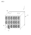
- FIG. 1 is a perspective view showing an entire structure of a dispensing device 1 according to an exemplary embodiment.
- FIG. 2 is a partially enlarged view showing a chamber 12 having a door 14 in a closed state according to an exemplary embodiment.
- FIG. 3 is a partially enlarged view showing the chamber 12 having the door 14 in an open state according to an exemplary embodiment.
- a dispensing device 1 capable of simultaneously dispensing a great number of welding rod dryers D generally known to those skilled in the art, as a device for receiving a welding rod (not shown), and preheating the welding rod for the use of the welding rod to prevent a cladding material of the welding rod from being stripped or wet with moisture.
- the welding rod dryer can be maintained at a predetermined temperature in the state that the welding rod dryer receives a welding rod without being stored separately from the welding rod, and many welding operators can rapidly dispense welding rod dryers at a time without difficulty and inconveniences.
- the dispensing device 1 includes a cabinet 10 including a plurality of chambers 12 that receive and encase welding rod dryers D, respectively, and the plurality of chambers are provided therein with respective connection members 20 to supply power so that the welding dryers D can be preheated; and a door 14 provided at an entrance of the chamber 12 and opened/closed through a typical hinged door scheme.
- the cabinet 10 has a predetermined width and length so that the plurality of chambers 12 in which the welding rod dryers D are received and encased may be provided as many as possible.
- the cabinet 10 is provided on a top surface thereof with a transferring member (not shown), such as a typical eye bolt, to transfer the welding rod dryer D.
- welding rod dryers are not stored in a plurality of chambers included in a cabinet separately from welding rods, but welding rod dryers having welding rods received therein are individually received and preheated in the chambers, respectively. Accordingly, since facilities to store the welding rods and the welding rod dryers are not required differently as from the related art, the space utilization can be optimized and maximized.
- the welding rod dryers D are individually provided into the chambers, which is included in the cabinet, respectively and preheated, so that many welding operators can rapidly dispense the welding rod dryers without a waiting time when the welding rod dryers are dispensed.
- the waste of time and manpower can be minimized, so that a high economical effect can be obtained, and the efficiency of a welding work can be enhanced since the welding rod can be instantly used after the welding rod is dispensed.
- the chambers 12 further include a timer 30 to set power supply time to the welding rod dryer D, that is, to adjust time to preheat the welding rod dryer D.
- a timer 30 to set power supply time to the welding rod dryer D, that is, to adjust time to preheat the welding rod dryer D.
- a single timer is provided for all chambers 12 provided in the cabinet 10, that is, one timer is provided for the cabinet 10.
- the exemplary embodiment is not limited thereto. That is, an individual timer may be provided for each chamber 12 of the cabinet 10.
- the welding rod dryer D may include an internal timer thereof. The timer is preferably provided in the connection member 20.
- the welding rod dryer D received and encased in the chamber 12 can be appropriately preheated for a time set by the timer 30 and can be smoothly preheated in time to dispense the welding rod dryer D.
- connection member 20 includes a plurality of connection parts 22 and 24 so that the connection member 20 can be selectively connected to a connection terminal D1 of the welding rod dryer D according to a shape of the connection terminal D1 of the welding rod dryer D.
- the connection parts 22 and 24 may include at least one of a ground-type connection part 22 and an outlet-type connection part 24.
- connection terminal D1 provided in the welding rod dryer D may be provided in the form of typical ground-type pin and plug according to a field condition of a working place.
- the ground-type connection part and the outlet-type connection part are provided in one connection member so that the connection member can be used regardless of the shape of the connection terminal D1. Accordingly, the use convenience and superior compatibility can be provided.
- connection member 20 includes a power switch (not shown), such as a typical on/off switch, to apply electricity, and an indication lamp 26 to indicate the operating state of the power switch so that an operator can determine the operating state of the power switch with naked eyes of the operator, the operator can easily determine a power on/off state through the indication lamp 26.
- a power switch such as a typical on/off switch
- circuit breakers 28 are provided on the top surface of the cabinet 10 or in the chambers 12 according to the number of the chambers 12 for the safe use when an abnormal situation, such as overvoltage or overcurrent, electrically occurs in the process of preheating the welding rod dryers D.
- the circuit breaker may be used by simultaneously connecting several chambers with each other according to design conditions.
- a dispensing card storing member 15 is further provided in the chamber 12 to determine a dispensing state of the welding rod dryer D received in the chamber 12.
- the dispensing card storing member 15 is provided in the form of a partition 15A perpendicularly formed to a bottom surface of the chamber 12 so that a dispensing card (not shown) may be disposed in an upright state at one side of the chamber 12.
- a sensor 32 is further provided in the chamber 12 to sense the receiving state of the welding rod dryer D.
- the sensor 32 may take in various forms of sensors, such as a weight sensor, an optical sensor, or a contact sensor, which is generally known to those skilled in the art, to sense the receiving state of the welding rod dryer D when the welding rod dryer D is received in the chamber 12.
- the sensor is connected with a typical control unit to sense the receiving state of the welding rod dryer so that a signal is transmitted to an operator or a central control unit or the receiving state is displayed.
- the operator can simply and conveniently determine if the welding rod dryer D to be stored and preheated is received normally in the chamber 12.
- an alarm unit 34 is further provided on the cabinet 10 or in the chamber 12 to determine if the cabinet 10 or the chamber 12 is in a normal state.
- the alarm unit 34 may include one of various alarm units connected with the control unit, which is generally known to those skilled in the art, to make an alarm sound through a typical speaker, or to notify the operator of the receiving state and the preheating state of the welding rod dryer D or the supply state of electricity through a screen serving as a display unit.
- the alarm unit 34 is realized in such a manner that the alarm unit 34 is connected with the generally-known control unit and components, such as the connection member 20, the circuit breaker 28, the indication lamp 26, or the sensor 32, related to the dispensing state or the preheating state of the welding rod dryer to perform an alarm function.
- a locking unit 140 is provided on front surfaces of the door 14 and the cabinet 10 making contact with the door 14 for the purpose of the safety and the prohibition on uses other than the use by an operator.
- the locking unit 140 is a typical locking chain used to lock the door 14 and the front surface of the cabinet 10 making contact with the door 14 when the door 14 is closed, and serves as a unit for operator restriction.
- the door 14 has a plurality of hinge parts 142 so that one side of the door 14 is rotatable.
- the door 14 has a handle 144 provided in an opposite side to the hinge parts 142 so that the user may more easily open the door 14.
- the door 14 includes a frame 14a, on which the hinge parts 142 and the handle 144 are provided, and a mesh part 14B allowing the user to view the chamber inward of the frame 14A and allowing the ventilation of the chamber.
- a display member 14C is further provided on a front surface of the door 14 to display items related to the chamber 12.
- the display member 14C is used to verify an identity of a welding operator so that only the verified welding operation may access the chamber 12.
- a plurality of cabinets 10 may be consecutively coupled to one another vertically or horizontally by typical coupling units, such as brackets, bolts, and nuts, according to occasions so that a great number of welding rod dryers may be stored.
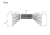
- the plurality of cabinets 10 are arranged in the state that doors face each other and a front or a rear thereof while making a passage, so that a space can be utilized as much as possible.
- the plurality of cabinets 10 are arranged in a substantially C shape, so that the maximum number of welding rod dryers D can be stored in the minimum space.
- the welding rod dryers can be smoothly dispensed without further delay. Further, high space utilization can be efficiently acquired.
- FIG. 5 is a perspective view showing a dispensing device 1 according to another exemplary embodiment.
- a single type of a dispensing device 1 is not manufactured. That is, the dispensing device is manufactured as a single module instead of being manufactured as a cabinet having a plurality of chambers, so that the minimum number of dispensing devices including one dispensing device to several tens of dispensing devices can be installed according to the working field conditions, a working space, or working conditions.
- the same reference numerals will be assigned to the same elements in a technical configuration the same as that described above.
- the dispensing device 1 includes a plurality of module-type bodies 10A.
- Each module-type body 10A includes a single chamber 12 receiving and encasing a welding rod dryer D.
- the chamber is provided with a connection member 20 to supply power to the welding rod dryer D and a door 14 provided at an entrance of the chamber 12.
- the module-type body 10A is provided on at least one surface thereof with a typical coupling unit 38A, such as a bracket, a bolt, and a nut, for the coupling with another module-type body 10A.
- the module-type body 10A typically has a rectangular parallelepiped shape to receive only one welding rod dryer D.
- the welding rod dryer D is not stored separately from a welding rod, but stored and preheated together with the welding rod in the state that the welding rod is inserted into the welding rod dryer D.
- the module-type body 10A can be conveniently stored in a place individually desired by an operator.
- module-type bodies 10A may be provided and united by typical coupling units according to installation conditions or fields.
- module-type body refers to the form of a single body
- unit refers to a combined form obtained by coupling single bodies to each other.
- the module-type bodies 10A are vertically stacked on each other or horizontally coupled to each other by the coupling unit 40 so that the module-type bodies 10A are united as a small unit for the use according to the installation conditions or the fields. Therefore, the module-type bodies may represent high practicality and high compatibility.
- the coupling unit 40 may be realized in various shapes that are generally known to those skilled in the art.
- the coupling unit can stack the multi-type bodies on each other or horizontally couple the multi-type bodies to each other by using a plurality of brackets or bolts and nuts.
- the coupling unit 40 may be provided in the form of a typical coupling protrusion or a typical coupling groove.
- the multi-type bodies may be stacked on each other or horizontally coupled with each other by forming the coupling protrusion and the coupling groove at corresponding positions of the multi-type bodies.
- various units which are generally known to those skilled in the art, may be used to vertically and horizontally couple the module-type bodies to each other.
- the module-type bodies are coupled to each other in necessary number by the coupling unit for the use according to the installation conditions or the field conditions of the working place. Accordingly, the module-type bodies may be assembled in appropriate size regardless of working conditions, so that a user can conveniently use the module-type bodies.
- a typical connection unit 40A is further provided on one surface of the module-type body 10A having the coupling unit so that the module-type body 10A can be electrically connected with another module-type body 10A.
- the connection units 42 such as a typical terminal and a connection terminal box, or a connection port and a connection box, preferably have a shape based on engagement for electrical connection and may typically include an outlet and a plug.
- module-type body 10A further include typical support members
- module-type body 10A such as typical brackets, rubber packing, or rolling wheels, engaged with the coupling unit provided on one surface of the module-type body 10A to safely and stably stack module-type bodies 10A.
- the module-type bodies 10A can be easily assembled in the form of a single unit required according to the field condition or the installation space by the coupling unit and the support member.
- the module-type body includes the timer to set power supply time for the welding rod dryer, the sensor, and the alarm unit, and the details thereof will be omitted since the above components have been described in the previous exemplary embodiments.
Landscapes
- Engineering & Computer Science (AREA)
- Mechanical Engineering (AREA)
- Physics & Mathematics (AREA)
- Plasma & Fusion (AREA)
- General Engineering & Computer Science (AREA)
- Life Sciences & Earth Sciences (AREA)
- Sustainable Development (AREA)
- Drying Of Solid Materials (AREA)
Abstract
Description
- Apparatuses consistent with exemplary embodiments relate to a dispensing device for a welding rod dryer, and more particularly, to a dispensing device for a welding rod dryer, in which the welding rod dryer can be maintained at a predetermined temperature in the state that the welding rod dryer receives a welding rod without being stored separately from the welding rod, and many welding operators can rapidly dispense welding rod dryers at a time without difficulty and inconveniences.
- Shielded metal arc welding (SMAW) is a technology first developed among arc welding technologies, and one of the technologies that have been most extensively used until now.
- According to the SMAW, an arc is generated between an electrode rod formed by coating a core with a cladding material and a base material for the welding work. The SMAW has been extensively used to mainly perform a welding work for mild steel, low alloy steel, stainless steel, or cast iron. In addition, since the SMAW has no special limitation in the thickness of a structure to be welded or a welding posture of a welding operator, the SMAW has been widely employed in shipbuilding, bridge, construction, and petroleum refining industries.
- A welding rod used in the SMAW is formed by coating a cladding material on an outer circumference of a metallic rod for generating an arc. If the cladding material of the welding rod is stripped or the welding rod becomes wet with moisture, the welding rod may not be operational, or the arc cannot be smoothly generated, so that a difficult situation in the use of the welding rod may frequently occur.
- Therefore, when the welding rod is stored, there is required a special caution of preventing the cladding material from being stripped or preventing the welding rod from becoming wet with moisture.
- Meanwhile, when storing the portable welding rod dryer, a welding rod remaining after the use thereof is separated from the welding rod dryer and put into a drying oven for the storage thereof, and the portable welding rod dryer is stacked and stored in a typical shelf.
- Accordingly, in the case of heavy industry fields, delay time is significantly taken until many welding operators select and receive their respective welding rod dryers at a time. In other words, predetermined time is required to preheat the portable welding rod dryer, and the welding operation must significantly and inconveniently be delayed for the welding rod dryer for time ranging from several tens of minutes to several hours.
- Accordingly, not only is too much time wasted, but also manpower of many welding operators is remarkably wasted. Further, since the welding rod stored in the drying oven must be drawn from the drying oven and received in the portable welding rod dryer again even though the heating of the portable welding rod dryer has been finished, procedures are remarkably complex and inconvenient.
- One or more exemplary embodiments provide a dispensing device for a welding rod dryer, in which the welding rod dryer can be maintained at a predetermined temperature in the state that the welding rod dryer receives a welding rod without being stored separately from the welding rod, and many welding operators can rapidly dispense welding rod dryers at a time without difficulty and inconveniences.
- One or more exemplary embodiments also provide a dispensing device for a welding rod dryer, capable of smoothly connecting the welding rod dryers with each other for the use of the welding rod dryers regardless of the shape of a connection terminal of the welding rod dryer.
- One or more exemplary embodiments provide a dispensing device for a welding rod dryer, which can be smoothly used in the form of a single unit.
- According to one aspect of an exemplary embodiment, there is provided a dispensing device for a welding rod dryer. The dispensing device may include a plurality of chambers configured to receive welding rod dryers; and a connection member provided in each of the plurality of chambers and configured to supply power to the welding dryers; and a door provided at an entrance of each of the plurality of chambers.
- The dispensing device may further include a timer configured to set power supply time to the welding rod dryer in the plurality of chambers.
- The timer may include a single timer configured to set the power supply time to the plurality chambers of the cabinet, or an individual timer provided in each of the plurality of chambers.
- Each welding rod dryer may include an internal timer configured to set power supply time for the welding rod dryer.
- The connection member may include a plurality of connection parts configured to selectively connect to supply the power to the welding dryers according to a shape of a connection terminal of the welding rod dryer.
- The connection part may include at least one of a ground-type connection part and an outlet-type connection part.
- The plurality of chambers may include circuit breakers according to a number of the plurality of chambers.
- The dispensing device may further include a dispensing card storing member provided in each of the plurality of chambers and configured to determine a dispensing state of the welding rod dryer received in a respective chamber.
- The dispensing device may further include a sensor provided in each chamber and configured to sense a receiving state of the welding rod dryer.
- The dispensing device may further include an alarm unit provided on the cabinet or in the chamber and configured to determine a state of the cabinet or the chamber.
- The dispensing device may further include a locking unit provided on a front surface of the door or the cabinet for a locking operation.
- According to an aspect of another exemplary embodiment, there is provided a dispensing device for a welding rod dryer. The dispensing device includes a plurality of module-type bodies, wherein a first module-type body of the plurality of module-type bodies may include: a chamber receiving a welding rod dryer; and a connection member provided in the chamber and configured to supply power to the welding rod dryer; and a door provided at an entrance of the chamber, and wherein the module-type body comprises a coupling unit provided on at least one surface and configured to couple with a second module-type body of the plurality of module-type bodies.
- The dispensing device may further include a connection unit provided on the least one surface of the first module-type body and configured to provide electrical connection with the second module-type body.
- The dispensing device may further include a support member provided in the first module-type body and coupled to the coupling unit provided at the at least one surface of the first module-type body.
- The dispensing device may further include a timer provided in the chamber and configured to set power supply time to the welding rod dryer.
- The timer may include a single timer configured to set the power supply time for the plurality of module-type bodies included in a unit, or an individual timer provided in each of the plurality of module-type bodies.
- The dispensing device may further include a sensor provided in the chamber and configured to sense a receiving state of the welding rod dryer.
- The dispensing device may further include a circuit breaker provided in the chamber.
- The dispensing device may further include a locking unit provided on a front surface of the module-type body or the door for a locking operation.
- The plurality of module-type bodies are assembled in a form of a single unit by the coupling unit and a support member.
- As described above, according to exemplary embodiments, the welding rod dryer can be maintained at a predetermined temperature in the state that the welding rod dryer receives a welding rod without being stored separately from the welding rod, and many welding operators can rapidly dispense welding rod dryers at a time without difficulty and inconveniences. Accordingly, the welding rod dryers can be dispensed within the shortest period of time, so that the high economical effects can be obtained.
- In addition, the welding rod received in the dispensed welding rod direr can be welded under the superior condition, so that the efficiency of the welding work can be improved.
- Further, the welding rod dryers can be smoothly connected with each other regardless of the shape of the connection terminal thereof, so that superior compatibility can be represented regardless of the connection terminals of the welding rod dryers.
- In addition, the dispensing device can be smoothly used in the form of a single unit, so that the dispensing device can be assembled in appropriate size according to the working conditions or the installation space. Accordingly the space utilization can be optimized and maximized.
-
-
FIG. 1 is a perspective view showing an entire structure of a dispensing device according to an exemplary embodiment. -
FIG. 2 is a partially enlarged view showing a chamber having a door in a closed state according to an exemplary embodiment. -
FIG. 3 is a partially enlarged view showing the chamber having the door in an open state an exemplary embodiment. -
FIG. 4 is a perspective view showing the arrangement of cabinets according to an exemplary embodiment. -
FIG. 5 is a partially exploded perspective view showing a dispensing device according to another exemplary embodiment. - Hereinafter, exemplary embodiments will be described in more detail with reference to accompanying drawings.
-
FIG. 1 is a perspective view showing an entire structure of a dispensingdevice 1 according to an exemplary embodiment.FIG. 2 is a partially enlarged view showing achamber 12 having adoor 14 in a closed state according to an exemplary embodiment.FIG. 3 is a partially enlarged view showing thechamber 12 having thedoor 14 in an open state according to an exemplary embodiment. - As shown in figures, provided is a
dispensing device 1 capable of simultaneously dispensing a great number of welding rod dryers D generally known to those skilled in the art, as a device for receiving a welding rod (not shown), and preheating the welding rod for the use of the welding rod to prevent a cladding material of the welding rod from being stripped or wet with moisture. - According to the exemplary embodiment, the welding rod dryer can be maintained at a predetermined temperature in the state that the welding rod dryer receives a welding rod without being stored separately from the welding rod, and many welding operators can rapidly dispense welding rod dryers at a time without difficulty and inconveniences.
- The
dispensing device 1 according to the exemplary includes acabinet 10 including a plurality ofchambers 12 that receive and encase welding rod dryers D, respectively, and the plurality of chambers are provided therein withrespective connection members 20 to supply power so that the welding dryers D can be preheated; and adoor 14 provided at an entrance of thechamber 12 and opened/closed through a typical hinged door scheme. Thecabinet 10 has a predetermined width and length so that the plurality ofchambers 12 in which the welding rod dryers D are received and encased may be provided as many as possible. Thecabinet 10 is provided on a top surface thereof with a transferring member (not shown), such as a typical eye bolt, to transfer the welding rod dryer D. - In other words, welding rod dryers are not stored in a plurality of chambers included in a cabinet separately from welding rods, but welding rod dryers having welding rods received therein are individually received and preheated in the chambers, respectively. Accordingly, since facilities to store the welding rods and the welding rod dryers are not required differently as from the related art, the space utilization can be optimized and maximized.
- In addition, the welding rod dryers D are individually provided into the chambers, which is included in the cabinet, respectively and preheated, so that many welding operators can rapidly dispense the welding rod dryers without a waiting time when the welding rod dryers are dispensed.
- Accordingly, differently from the related art, the waste of time and manpower can be minimized, so that a high economical effect can be obtained, and the efficiency of a welding work can be enhanced since the welding rod can be instantly used after the welding rod is dispensed.
- The
chambers 12 further include atimer 30 to set power supply time to the welding rod dryer D, that is, to adjust time to preheat the welding rod dryer D. In the exemplary embodiment, a single timer is provided for allchambers 12 provided in thecabinet 10, that is, one timer is provided for thecabinet 10. However, the exemplary embodiment is not limited thereto. That is, an individual timer may be provided for eachchamber 12 of thecabinet 10. In addition, the welding rod dryer D may include an internal timer thereof. The timer is preferably provided in theconnection member 20. - Accordingly, the welding rod dryer D received and encased in the
chamber 12 can be appropriately preheated for a time set by thetimer 30 and can be smoothly preheated in time to dispense the welding rod dryer D. - The
connection member 20 includes a plurality ofconnection parts connection member 20 can be selectively connected to a connection terminal D1 of the welding rod dryer D according to a shape of the connection terminal D1 of the welding rod dryer D. Theconnection parts type connection part 22 and an outlet-type connection part 24. - In other words, the connection terminal D1 provided in the welding rod dryer D may be provided in the form of typical ground-type pin and plug according to a field condition of a working place. However, the ground-type connection part and the outlet-type connection part are provided in one connection member so that the connection member can be used regardless of the shape of the connection terminal D1. Accordingly, the use convenience and superior compatibility can be provided.
- In addition, as the
connection member 20 includes a power switch (not shown), such as a typical on/off switch, to apply electricity, and anindication lamp 26 to indicate the operating state of the power switch so that an operator can determine the operating state of the power switch with naked eyes of the operator, the operator can easily determine a power on/off state through theindication lamp 26. - In addition,
circuit breakers 28 are provided on the top surface of thecabinet 10 or in thechambers 12 according to the number of thechambers 12 for the safe use when an abnormal situation, such as overvoltage or overcurrent, electrically occurs in the process of preheating the welding rod dryers D. In this case, the circuit breaker may be used by simultaneously connecting several chambers with each other according to design conditions. - In addition, a dispensing
card storing member 15 is further provided in thechamber 12 to determine a dispensing state of the welding rod dryer D received in thechamber 12. The dispensingcard storing member 15 is provided in the form of apartition 15A perpendicularly formed to a bottom surface of thechamber 12 so that a dispensing card (not shown) may be disposed in an upright state at one side of thechamber 12. - Accordingly, an operator can simply and conveniently determine the dispensing state of the welding rod dryer D stored in the
chamber 12. - In addition, a
sensor 32 is further provided in thechamber 12 to sense the receiving state of the welding rod dryer D. Thesensor 32 may take in various forms of sensors, such as a weight sensor, an optical sensor, or a contact sensor, which is generally known to those skilled in the art, to sense the receiving state of the welding rod dryer D when the welding rod dryer D is received in thechamber 12. In this case, the sensor is connected with a typical control unit to sense the receiving state of the welding rod dryer so that a signal is transmitted to an operator or a central control unit or the receiving state is displayed. - Accordingly, the operator can simply and conveniently determine if the welding rod dryer D to be stored and preheated is received normally in the
chamber 12. - In addition, an
alarm unit 34 is further provided on thecabinet 10 or in thechamber 12 to determine if thecabinet 10 or thechamber 12 is in a normal state. Thealarm unit 34 may include one of various alarm units connected with the control unit, which is generally known to those skilled in the art, to make an alarm sound through a typical speaker, or to notify the operator of the receiving state and the preheating state of the welding rod dryer D or the supply state of electricity through a screen serving as a display unit. In addition, preferably, thealarm unit 34 is realized in such a manner that thealarm unit 34 is connected with the generally-known control unit and components, such as theconnection member 20, thecircuit breaker 28, theindication lamp 26, or thesensor 32, related to the dispensing state or the preheating state of the welding rod dryer to perform an alarm function. - Referring to
FIG. 2 , alocking unit 140 is provided on front surfaces of thedoor 14 and thecabinet 10 making contact with thedoor 14 for the purpose of the safety and the prohibition on uses other than the use by an operator. In other words, thelocking unit 140 is a typical locking chain used to lock thedoor 14 and the front surface of thecabinet 10 making contact with thedoor 14 when thedoor 14 is closed, and serves as a unit for operator restriction. - In addition, the
door 14 has a plurality ofhinge parts 142 so that one side of thedoor 14 is rotatable. In addition, thedoor 14 has ahandle 144 provided in an opposite side to thehinge parts 142 so that the user may more easily open thedoor 14. - In addition, the
door 14 includes a frame 14a, on which thehinge parts 142 and thehandle 144 are provided, and amesh part 14B allowing the user to view the chamber inward of theframe 14A and allowing the ventilation of the chamber. - A
display member 14C is further provided on a front surface of thedoor 14 to display items related to thechamber 12. In other words, thedisplay member 14C is used to verify an identity of a welding operator so that only the verified welding operation may access thechamber 12. - In addition, a plurality of
cabinets 10 may be consecutively coupled to one another vertically or horizontally by typical coupling units, such as brackets, bolts, and nuts, according to occasions so that a great number of welding rod dryers may be stored. - As shown in
FIG. 4 , the plurality ofcabinets 10 are arranged in the state that doors face each other and a front or a rear thereof while making a passage, so that a space can be utilized as much as possible. In other words, the plurality ofcabinets 10 are arranged in a substantially C shape, so that the maximum number of welding rod dryers D can be stored in the minimum space. - Therefore, even if much manpower is simultaneously mobilized when the welding rod dryers are dispensed, the welding rod dryers can be smoothly dispensed without further delay. Further, high space utilization can be efficiently acquired.
-
FIG. 5 is a perspective view showing adispensing device 1 according to another exemplary embodiment. - As shown in
FIG. 5 , a single type of adispensing device 1 is not manufactured. That is, the dispensing device is manufactured as a single module instead of being manufactured as a cabinet having a plurality of chambers, so that the minimum number of dispensing devices including one dispensing device to several tens of dispensing devices can be installed according to the working field conditions, a working space, or working conditions. In addition, the same reference numerals will be assigned to the same elements in a technical configuration the same as that described above. - The
dispensing device 1 according to the exemplary embodiment includes a plurality of module-type bodies 10A. Each module-type body 10A includes asingle chamber 12 receiving and encasing a welding rod dryer D. The chamber is provided with aconnection member 20 to supply power to the welding rod dryer D and adoor 14 provided at an entrance of thechamber 12. The module-type body 10A is provided on at least one surface thereof with a typical coupling unit 38A, such as a bracket, a bolt, and a nut, for the coupling with another module-type body 10A. - The module-
type body 10A typically has a rectangular parallelepiped shape to receive only one welding rod dryer D. Different from the related art, the welding rod dryer D is not stored separately from a welding rod, but stored and preheated together with the welding rod in the state that the welding rod is inserted into the welding rod dryer D. - Therefore, the module-
type body 10A can be conveniently stored in a place individually desired by an operator. - Meanwhile, a plurality of module-
type bodies 10A may be provided and united by typical coupling units according to installation conditions or fields. The term "module-type body" refers to the form of a single body, and the term "unit" refers to a combined form obtained by coupling single bodies to each other. - In other words, the module-
type bodies 10A are vertically stacked on each other or horizontally coupled to each other by thecoupling unit 40 so that the module-type bodies 10A are united as a small unit for the use according to the installation conditions or the fields. Therefore, the module-type bodies may represent high practicality and high compatibility. - Further, the
coupling unit 40 may be realized in various shapes that are generally known to those skilled in the art. For example, the coupling unit can stack the multi-type bodies on each other or horizontally couple the multi-type bodies to each other by using a plurality of brackets or bolts and nuts. - In addition, the
coupling unit 40 may be provided in the form of a typical coupling protrusion or a typical coupling groove. The multi-type bodies may be stacked on each other or horizontally coupled with each other by forming the coupling protrusion and the coupling groove at corresponding positions of the multi-type bodies. - In addition to the
coupling unit 40, various units, which are generally known to those skilled in the art, may be used to vertically and horizontally couple the module-type bodies to each other. - Therefore, the module-type bodies are coupled to each other in necessary number by the coupling unit for the use according to the installation conditions or the field conditions of the working place. Accordingly, the module-type bodies may be assembled in appropriate size regardless of working conditions, so that a user can conveniently use the module-type bodies.
- A typical connection unit 40A is further provided on one surface of the module-
type body 10A having the coupling unit so that the module-type body 10A can be electrically connected with another module-type body 10A. Theconnection units 42, such as a typical terminal and a connection terminal box, or a connection port and a connection box, preferably have a shape based on engagement for electrical connection and may typically include an outlet and a plug. - In addition, the module-
type body 10A further include typical support members - (not shown), such as typical brackets, rubber packing, or rolling wheels, engaged with the coupling unit provided on one surface of the module-
type body 10A to safely and stably stack module-type bodies 10A. - Therefore, the module-
type bodies 10A can be easily assembled in the form of a single unit required according to the field condition or the installation space by the coupling unit and the support member. - Meanwhile, the module-type body includes the timer to set power supply time for the welding rod dryer, the sensor, and the alarm unit, and the details thereof will be omitted since the above components have been described in the previous exemplary embodiments.
- While exemplary embodiments have been particularly shown and described above, it would be appreciated by those skilled in the art that various changes may be made therein without departing from the scope and spirit of the present inventive concept as defined by the following claims.
Claims (15)
- A dispensing device for a welding rod dryer, the dispensing device comprising a cabinet comprising:a plurality of chambers configured to receive welding rod dryers; anda connection member provided in each of the plurality of chambers and configured to supply power to the welding dryers; anda door provided at an entrance of each of the plurality of chambers.
- The dispensing device of claim 1, further comprising a timer configured to set power supply time to the welding rod dryer in the plurality of chambers.
- The dispensing device of claim 2, wherein the timer comprises a single timer configured to set the power supply time to the plurality chambers of the cabinet, or an individual timer provided in each of the plurality of chambers.
- The dispensing device of claim 1, wherein the connection member comprises a plurality of connection parts configured to selectively connect to supply the power to the welding dryers according to a shape of a connection terminal of the welding rod dryer.
- The dispensing device of claim 4, wherein the connection part comprises at least one of a ground-type connection part and an outlet-type connection part.
- The dispensing device of claim 1, wherein the plurality of chambers comprise circuit breakers according to a number of the plurality of chambers.
- The dispensing device of claim 1, further comprising a dispensing card storing member provided in each of the plurality of chambers and configured to determine a dispensing state of the welding rod dryer received in a respective chamber.
- The dispensing device of claim 1, further comprising a sensor provided in each chamber and configured to sense a receiving state of the welding rod dryer.
- The dispensing device of claim 1, further comprising an alarm unit provided on the cabinet or in the chamber and configured to determine a state of the cabinet or the chamber.
- A dispensing device for a welding rod dryer, the dispensing device comprising a plurality of module-type bodies,
wherein a first module-type body of the plurality of module-type bodies comprises:a chamber receiving a welding rod dryer; anda connection member provided in the chamber and configured to supply power to the welding rod dryer; anda door provided at an entrance of the chamber, andwherein the first module-type body comprises a coupling unit provided on at least one surface and configured to couple with a second module-type body of the plurality of module-type bodies. - The dispensing device of claim 10, further comprising a connection unit provided on the least one surface of the first module-type body and configured to provide electrical connection with the second module-type body.
- The dispensing device of claim 10, further comprising a support member provided in the first module-type body and coupled to the coupling unit provided at the at least one surface of the first module-type body.
- The dispensing device of claim 10, further comprising a timer provided in the chamber and configured to set power supply time to the welding rod dryer.
- The dispensing device of claim 13, wherein the timer comprises a single timer configured to set the power supply time for the plurality of module-type bodies included in a unit, or an individual timer provided in each of the plurality of module-type bodies.
- The dispensing device of claim 10, further comprising a sensor provided in the chamber and configured to sense a receiving state of the welding rod dryer.
Applications Claiming Priority (1)
| Application Number | Priority Date | Filing Date | Title |
|---|---|---|---|
| KR1020130158535A KR101569890B1 (en) | 2013-12-18 | 2013-12-18 | Welding rod dryer dispenser |
Publications (3)
| Publication Number | Publication Date |
|---|---|
| EP2894002A2 true EP2894002A2 (en) | 2015-07-15 |
| EP2894002A3 EP2894002A3 (en) | 2015-08-26 |
| EP2894002B1 EP2894002B1 (en) | 2022-11-02 |
Family
ID=52101141
Family Applications (1)
| Application Number | Title | Priority Date | Filing Date |
|---|---|---|---|
| EP14197683.7A Active EP2894002B1 (en) | 2013-12-18 | 2014-12-12 | Dispensing device for welding rod dryer |
Country Status (5)
| Country | Link |
|---|---|
| US (1) | US9551528B2 (en) |
| EP (1) | EP2894002B1 (en) |
| JP (1) | JP6642963B2 (en) |
| KR (1) | KR101569890B1 (en) |
| CN (1) | CN104729273B (en) |
Families Citing this family (8)
| Publication number | Priority date | Publication date | Assignee | Title |
|---|---|---|---|---|
| KR101569890B1 (en) * | 2013-12-18 | 2015-11-17 | 두산중공업 주식회사 | Welding rod dryer dispenser |
| US11690927B2 (en) | 2016-02-04 | 2023-07-04 | Xenex Disinfection Services Inc. | Systems, cabinets and methods for disinfecting objects |
| US11648326B2 (en) * | 2016-02-04 | 2023-05-16 | Xenex Disinfection Services Inc. | Cabinets for disinfecting objects |
| CN106766856A (en) * | 2016-11-19 | 2017-05-31 | 剑河县坡王生态农业有限责任公司 | A kind of foldable fish pond feed for fish farming drying device |
| CN112097492A (en) * | 2020-09-28 | 2020-12-18 | 五矿联众(天津)焊接材料有限公司 | Heating device is adjusted with many grades to welding rod processing |
| CN113733035B (en) * | 2021-08-31 | 2023-01-20 | 国网河南省电力公司博爱县供电公司 | Power supply equipment maintenance tool storage rack for power supply company |
| CN113895789B (en) * | 2021-10-29 | 2023-02-14 | 中国核工业二三建设有限公司 | Welding rod heat-preserving container |
| KR102735369B1 (en) | 2022-05-04 | 2024-11-28 | 주식회사 세아에삽 | Method of welding using the welding rod marked with thermocromic pigment and method for manufacturing of welding rod the same |
Family Cites Families (35)
| Publication number | Priority date | Publication date | Assignee | Title |
|---|---|---|---|---|
| GB553171A (en) * | 1941-11-03 | 1943-05-11 | Arc Mfg Company Ltd | Improvements in or relating to the manufacture of metal welding rods |
| US2350672A (en) * | 1942-08-05 | 1944-06-06 | J O Ross Engineering Corp | Drier |
| US3489398A (en) * | 1968-06-27 | 1970-01-13 | Moslo Machinery Co | Welding rod handling and baking system |
| JPS5254588Y2 (en) * | 1972-03-06 | 1977-12-10 | ||
| SE359763B (en) * | 1972-03-30 | 1973-09-10 | Elektriska Svetsnings Ab | |
| JPS533493B2 (en) * | 1973-03-26 | 1978-02-07 | ||
| JPS538647Y2 (en) * | 1975-07-16 | 1978-03-07 | ||
| JPS52135454A (en) * | 1976-05-08 | 1977-11-12 | Miyaura Denki Seisakushiyo Kk | Structure for welding rod drying machine |
| CH638032A5 (en) * | 1979-02-22 | 1983-08-31 | Paul Studer | Device for drying bar-shaped welding electrodes |
| JPS5665790U (en) * | 1979-10-20 | 1981-06-02 | ||
| JPS6286978U (en) * | 1985-11-20 | 1987-06-03 | ||
| JPH10162241A (en) * | 1996-11-06 | 1998-06-19 | K N Technos Kk | Charged power automatic vending machine for portable telephone set |
| KR0131734Y1 (en) | 1995-11-22 | 1999-01-15 | 이종하 | Welding Rod Dryer |
| US5911487A (en) * | 1996-09-23 | 1999-06-15 | Robert L. Dricken | Vacuum degasser tank |
| US6075226A (en) * | 1998-10-20 | 2000-06-13 | Kishbaugh; Daniel J. | Portable holding oven for welding electrodes utilizing exhaust heat from welding machine |
| DE29910310U1 (en) * | 1999-06-12 | 1999-08-26 | Meier, Hans-Jürgen, 79114 Freiburg | Device for charging accumulators and for storing mobile phones |
| KR200248562Y1 (en) | 1999-06-25 | 2001-10-31 | 강규석 | a welding rod drying device |
| US6219937B1 (en) * | 2000-03-30 | 2001-04-24 | George R. Culp | Reheaters for kilns, reheater-like structures, and associated methods |
| US6528764B2 (en) * | 2000-07-07 | 2003-03-04 | Mark Podgurski | Engine exhaust heated welding rod drying oven |
| KR200218613Y1 (en) | 2000-10-06 | 2001-04-02 | 명병수 | Portable Electrode Dryer |
| KR100368468B1 (en) * | 2001-03-16 | 2003-01-24 | 박관순 | Drying method of welding electrode and drying system for the method |
| JP4460184B2 (en) * | 2001-03-27 | 2010-05-12 | 株式会社岡村製作所 | cabinet |
| JP2002303445A (en) * | 2001-04-02 | 2002-10-18 | Tadashi Sakamaki | Device for preventing temperature rise within server cabinet |
| JP2003025070A (en) * | 2001-07-09 | 2003-01-28 | Hitachi Plant Eng & Constr Co Ltd | Welding rod retrieval device |
| US6924460B1 (en) * | 2004-01-27 | 2005-08-02 | Lincoln Global, Inc. | Engine welder with shielding gas generation |
| DE202006006702U1 (en) * | 2006-04-26 | 2006-06-14 | Ackermann, Marc | Safe deposit box for keeping of small electronic devices has lockable case, into which power supply is installed whereby inner power supply is controlled by means of contact switch integrated in door mechanism |
| CN201427754Y (en) * | 2009-04-11 | 2010-03-24 | 任建国 | Free off cap electrode insulating cylinder |
| DE102011009898A1 (en) * | 2011-01-31 | 2012-08-02 | Castellan Ag | Device for receiving and temporarily storing battery-operated electronic device e.g. mobile phone, has charging unit for charging battery of electronic device, and accounting unit that obtains amount of energy charged to battery |
| CN202151758U (en) * | 2011-06-27 | 2012-02-29 | 武汉一冶钢结构有限责任公司 | Pressing pop-up thermal insulation barrel for welding rods |
| KR20130093282A (en) * | 2012-02-14 | 2013-08-22 | 현대중공업 주식회사 | System and method for managing materials |
| CN102601557B (en) * | 2012-03-29 | 2014-12-17 | 永煤集团股份有限公司新桥煤矿 | Electric welding storage rack |
| KR101348390B1 (en) * | 2012-05-01 | 2014-01-07 | 일흥산업(주) | a welding rod drying device for wire feeder |
| CN103176488A (en) * | 2013-02-17 | 2013-06-26 | 葫芦岛市滨海宇通自动化控制有限公司 | Control device for welding rod warm box |
| KR101569890B1 (en) * | 2013-12-18 | 2015-11-17 | 두산중공업 주식회사 | Welding rod dryer dispenser |
| KR101469415B1 (en) * | 2014-05-01 | 2014-12-04 | 김연수 | A canister of welding rod |
-
2013
- 2013-12-18 KR KR1020130158535A patent/KR101569890B1/en active Active
-
2014
- 2014-12-02 JP JP2014243919A patent/JP6642963B2/en active Active
- 2014-12-10 CN CN201410751646.3A patent/CN104729273B/en active Active
- 2014-12-12 EP EP14197683.7A patent/EP2894002B1/en active Active
- 2014-12-17 US US14/573,836 patent/US9551528B2/en active Active
Non-Patent Citations (1)
| Title |
|---|
| None |
Also Published As
| Publication number | Publication date |
|---|---|
| KR101569890B1 (en) | 2015-11-17 |
| EP2894002A3 (en) | 2015-08-26 |
| CN104729273A (en) | 2015-06-24 |
| JP2015116611A (en) | 2015-06-25 |
| CN104729273B (en) | 2017-04-12 |
| US9551528B2 (en) | 2017-01-24 |
| US20150168063A1 (en) | 2015-06-18 |
| JP6642963B2 (en) | 2020-02-12 |
| EP2894002B1 (en) | 2022-11-02 |
| KR20150071466A (en) | 2015-06-26 |
Similar Documents
| Publication | Publication Date | Title |
|---|---|---|
| US9551528B2 (en) | Dispensing device for welding rod dryer | |
| CN101583984B (en) | Security display unit with central control system | |
| US20180213670A1 (en) | Protective Cabinet for Storage and Protection of Equipment in General | |
| US20140097797A1 (en) | Energy storage system | |
| US10153118B2 (en) | Frame module, circuit breaker including the same and associated method | |
| US20170163062A9 (en) | Wearable / mountable mobile charging device | |
| CN107110908B (en) | Testing and monitoring of electrical connections | |
| US20160056428A1 (en) | Rack housing assembly and energy storage apparatus having the same | |
| KR101622445B1 (en) | switchergear having pressure relief route structure | |
| JPWO2017006588A1 (en) | Power supply | |
| JP2025170422A (en) | Energy storage system | |
| KR100975762B1 (en) | Multiple function type distributing apparatus of structure | |
| EP3161914B1 (en) | Motor control center with an automatic fused grounding of the load terminals | |
| KR200484178Y1 (en) | Multi-Charging System | |
| US2799852A (en) | Current responsive signal devices | |
| CN206442000U (en) | A kind of switch cabinet body of easy disassembly | |
| GB2528853A (en) | Trading post with moveable display stand | |
| EP3339764B1 (en) | Device for heating a room, assemblable modular heating system therewith and process for producing the device | |
| JP5033048B2 (en) | Distribution board | |
| AU2013200615A1 (en) | Security Trolley with Charging Facility | |
| CN208496932U (en) | Tool hanging board for power distribution live work | |
| EP4088878B1 (en) | Multifunctional channel and cabinet provided with one or more channels | |
| US1729877A (en) | Fuse-panel box | |
| JP3909464B2 (en) | Monitor monitoring rack | |
| JP2017077143A (en) | Power conversion device |
Legal Events
| Date | Code | Title | Description |
|---|---|---|---|
| PUAI | Public reference made under article 153(3) epc to a published international application that has entered the european phase |
Free format text: ORIGINAL CODE: 0009012 |
|
| 17P | Request for examination filed |
Effective date: 20141212 |
|
| AK | Designated contracting states |
Kind code of ref document: A2 Designated state(s): AL AT BE BG CH CY CZ DE DK EE ES FI FR GB GR HR HU IE IS IT LI LT LU LV MC MK MT NL NO PL PT RO RS SE SI SK SM TR |
|
| AX | Request for extension of the european patent |
Extension state: BA ME |
|
| PUAL | Search report despatched |
Free format text: ORIGINAL CODE: 0009013 |
|
| RIC1 | Information provided on ipc code assigned before grant |
Ipc: F26B 9/00 20060101ALI20150709BHEP Ipc: B23K 9/32 20060101AFI20150709BHEP Ipc: B65D 85/26 20060101ALI20150709BHEP Ipc: B23K 9/26 20060101ALI20150709BHEP Ipc: B65D 21/02 20060101ALI20150709BHEP Ipc: B25H 3/00 20060101ALI20150709BHEP |
|
| RIC1 | Information provided on ipc code assigned before grant |
Ipc: B65D 21/02 20060101ALI20150710BHEP Ipc: B23K 9/32 20060101AFI20150710BHEP Ipc: B23K 9/26 20060101ALI20150710BHEP Ipc: F26B 9/00 20060101ALI20150710BHEP Ipc: B65D 85/26 20060101ALI20150710BHEP Ipc: B25H 3/00 20060101ALI20150710BHEP |
|
| AK | Designated contracting states |
Kind code of ref document: A3 Designated state(s): AL AT BE BG CH CY CZ DE DK EE ES FI FR GB GR HR HU IE IS IT LI LT LU LV MC MK MT NL NO PL PT RO RS SE SI SK SM TR |
|
| AX | Request for extension of the european patent |
Extension state: BA ME |
|
| RIC1 | Information provided on ipc code assigned before grant |
Ipc: B25H 3/00 20060101ALI20150717BHEP Ipc: B65D 21/02 20060101ALI20150717BHEP Ipc: B65D 85/26 20060101ALI20150717BHEP Ipc: F26B 9/00 20060101ALI20150717BHEP Ipc: B23K 9/32 20060101AFI20150717BHEP Ipc: B23K 9/26 20060101ALI20150717BHEP |
|
| R17P | Request for examination filed (corrected) |
Effective date: 20160120 |
|
| RBV | Designated contracting states (corrected) |
Designated state(s): AL AT BE BG CH CY CZ DE DK EE ES FI FR GB GR HR HU IE IS IT LI LT LU LV MC MK MT NL NO PL PT RO RS SE SI SK SM TR |
|
| STAA | Information on the status of an ep patent application or granted ep patent |
Free format text: STATUS: EXAMINATION IS IN PROGRESS |
|
| 17Q | First examination report despatched |
Effective date: 20190405 |
|
| GRAP | Despatch of communication of intention to grant a patent |
Free format text: ORIGINAL CODE: EPIDOSNIGR1 |
|
| STAA | Information on the status of an ep patent application or granted ep patent |
Free format text: STATUS: GRANT OF PATENT IS INTENDED |
|
| INTG | Intention to grant announced |
Effective date: 20220517 |
|
| RIN1 | Information on inventor provided before grant (corrected) |
Inventor name: OH, EUN JONG Inventor name: KONG, HYUN SANG |
|
| GRAS | Grant fee paid |
Free format text: ORIGINAL CODE: EPIDOSNIGR3 |
|
| GRAA | (expected) grant |
Free format text: ORIGINAL CODE: 0009210 |
|
| STAA | Information on the status of an ep patent application or granted ep patent |
Free format text: STATUS: THE PATENT HAS BEEN GRANTED |
|
| RAP3 | Party data changed (applicant data changed or rights of an application transferred) |
Owner name: DOOSAN ENERBILITY CO., LTD. |
|
| AK | Designated contracting states |
Kind code of ref document: B1 Designated state(s): AL AT BE BG CH CY CZ DE DK EE ES FI FR GB GR HR HU IE IS IT LI LT LU LV MC MK MT NL NO PL PT RO RS SE SI SK SM TR |
|
| REG | Reference to a national code |
Ref country code: GB Ref legal event code: FG4D |
|
| REG | Reference to a national code |
Ref country code: CH Ref legal event code: EP Ref country code: AT Ref legal event code: REF Ref document number: 1528403 Country of ref document: AT Kind code of ref document: T Effective date: 20221115 |
|
| REG | Reference to a national code |
Ref country code: DE Ref legal event code: R096 Ref document number: 602014085392 Country of ref document: DE |
|
| REG | Reference to a national code |
Ref country code: IE Ref legal event code: FG4D |
|
| REG | Reference to a national code |
Ref country code: LT Ref legal event code: MG9D |
|
| REG | Reference to a national code |
Ref country code: NL Ref legal event code: MP Effective date: 20221102 |
|
| REG | Reference to a national code |
Ref country code: AT Ref legal event code: MK05 Ref document number: 1528403 Country of ref document: AT Kind code of ref document: T Effective date: 20221102 |
|
| PG25 | Lapsed in a contracting state [announced via postgrant information from national office to epo] |
Ref country code: SE Free format text: LAPSE BECAUSE OF FAILURE TO SUBMIT A TRANSLATION OF THE DESCRIPTION OR TO PAY THE FEE WITHIN THE PRESCRIBED TIME-LIMIT Effective date: 20221102 Ref country code: PT Free format text: LAPSE BECAUSE OF FAILURE TO SUBMIT A TRANSLATION OF THE DESCRIPTION OR TO PAY THE FEE WITHIN THE PRESCRIBED TIME-LIMIT Effective date: 20230302 Ref country code: NO Free format text: LAPSE BECAUSE OF FAILURE TO SUBMIT A TRANSLATION OF THE DESCRIPTION OR TO PAY THE FEE WITHIN THE PRESCRIBED TIME-LIMIT Effective date: 20230202 Ref country code: LT Free format text: LAPSE BECAUSE OF FAILURE TO SUBMIT A TRANSLATION OF THE DESCRIPTION OR TO PAY THE FEE WITHIN THE PRESCRIBED TIME-LIMIT Effective date: 20221102 Ref country code: FI Free format text: LAPSE BECAUSE OF FAILURE TO SUBMIT A TRANSLATION OF THE DESCRIPTION OR TO PAY THE FEE WITHIN THE PRESCRIBED TIME-LIMIT Effective date: 20221102 Ref country code: ES Free format text: LAPSE BECAUSE OF FAILURE TO SUBMIT A TRANSLATION OF THE DESCRIPTION OR TO PAY THE FEE WITHIN THE PRESCRIBED TIME-LIMIT Effective date: 20221102 Ref country code: AT Free format text: LAPSE BECAUSE OF FAILURE TO SUBMIT A TRANSLATION OF THE DESCRIPTION OR TO PAY THE FEE WITHIN THE PRESCRIBED TIME-LIMIT Effective date: 20221102 |
|
| PG25 | Lapsed in a contracting state [announced via postgrant information from national office to epo] |
Ref country code: RS Free format text: LAPSE BECAUSE OF FAILURE TO SUBMIT A TRANSLATION OF THE DESCRIPTION OR TO PAY THE FEE WITHIN THE PRESCRIBED TIME-LIMIT Effective date: 20221102 Ref country code: PL Free format text: LAPSE BECAUSE OF FAILURE TO SUBMIT A TRANSLATION OF THE DESCRIPTION OR TO PAY THE FEE WITHIN THE PRESCRIBED TIME-LIMIT Effective date: 20221102 Ref country code: LV Free format text: LAPSE BECAUSE OF FAILURE TO SUBMIT A TRANSLATION OF THE DESCRIPTION OR TO PAY THE FEE WITHIN THE PRESCRIBED TIME-LIMIT Effective date: 20221102 Ref country code: IS Free format text: LAPSE BECAUSE OF FAILURE TO SUBMIT A TRANSLATION OF THE DESCRIPTION OR TO PAY THE FEE WITHIN THE PRESCRIBED TIME-LIMIT Effective date: 20230302 Ref country code: HR Free format text: LAPSE BECAUSE OF FAILURE TO SUBMIT A TRANSLATION OF THE DESCRIPTION OR TO PAY THE FEE WITHIN THE PRESCRIBED TIME-LIMIT Effective date: 20221102 Ref country code: GR Free format text: LAPSE BECAUSE OF FAILURE TO SUBMIT A TRANSLATION OF THE DESCRIPTION OR TO PAY THE FEE WITHIN THE PRESCRIBED TIME-LIMIT Effective date: 20230203 |
|
| PG25 | Lapsed in a contracting state [announced via postgrant information from national office to epo] |
Ref country code: NL Free format text: LAPSE BECAUSE OF FAILURE TO SUBMIT A TRANSLATION OF THE DESCRIPTION OR TO PAY THE FEE WITHIN THE PRESCRIBED TIME-LIMIT Effective date: 20221102 |
|
| PG25 | Lapsed in a contracting state [announced via postgrant information from national office to epo] |
Ref country code: SM Free format text: LAPSE BECAUSE OF FAILURE TO SUBMIT A TRANSLATION OF THE DESCRIPTION OR TO PAY THE FEE WITHIN THE PRESCRIBED TIME-LIMIT Effective date: 20221102 Ref country code: RO Free format text: LAPSE BECAUSE OF FAILURE TO SUBMIT A TRANSLATION OF THE DESCRIPTION OR TO PAY THE FEE WITHIN THE PRESCRIBED TIME-LIMIT Effective date: 20221102 Ref country code: EE Free format text: LAPSE BECAUSE OF FAILURE TO SUBMIT A TRANSLATION OF THE DESCRIPTION OR TO PAY THE FEE WITHIN THE PRESCRIBED TIME-LIMIT Effective date: 20221102 Ref country code: DK Free format text: LAPSE BECAUSE OF FAILURE TO SUBMIT A TRANSLATION OF THE DESCRIPTION OR TO PAY THE FEE WITHIN THE PRESCRIBED TIME-LIMIT Effective date: 20221102 Ref country code: CZ Free format text: LAPSE BECAUSE OF FAILURE TO SUBMIT A TRANSLATION OF THE DESCRIPTION OR TO PAY THE FEE WITHIN THE PRESCRIBED TIME-LIMIT Effective date: 20221102 |
|
| REG | Reference to a national code |
Ref country code: CH Ref legal event code: PL |
|
| REG | Reference to a national code |
Ref country code: DE Ref legal event code: R097 Ref document number: 602014085392 Country of ref document: DE |
|
| REG | Reference to a national code |
Ref country code: BE Ref legal event code: MM Effective date: 20221231 |
|
| PG25 | Lapsed in a contracting state [announced via postgrant information from national office to epo] |
Ref country code: SK Free format text: LAPSE BECAUSE OF FAILURE TO SUBMIT A TRANSLATION OF THE DESCRIPTION OR TO PAY THE FEE WITHIN THE PRESCRIBED TIME-LIMIT Effective date: 20221102 Ref country code: LU Free format text: LAPSE BECAUSE OF NON-PAYMENT OF DUE FEES Effective date: 20221212 Ref country code: AL Free format text: LAPSE BECAUSE OF FAILURE TO SUBMIT A TRANSLATION OF THE DESCRIPTION OR TO PAY THE FEE WITHIN THE PRESCRIBED TIME-LIMIT Effective date: 20221102 |
|
| PLBE | No opposition filed within time limit |
Free format text: ORIGINAL CODE: 0009261 |
|
| STAA | Information on the status of an ep patent application or granted ep patent |
Free format text: STATUS: NO OPPOSITION FILED WITHIN TIME LIMIT |
|
| 26N | No opposition filed |
Effective date: 20230803 |
|
| GBPC | Gb: european patent ceased through non-payment of renewal fee |
Effective date: 20230202 |
|
| PG25 | Lapsed in a contracting state [announced via postgrant information from national office to epo] |
Ref country code: LI Free format text: LAPSE BECAUSE OF NON-PAYMENT OF DUE FEES Effective date: 20221231 Ref country code: IE Free format text: LAPSE BECAUSE OF NON-PAYMENT OF DUE FEES Effective date: 20221212 Ref country code: CH Free format text: LAPSE BECAUSE OF NON-PAYMENT OF DUE FEES Effective date: 20221231 |
|
| PG25 | Lapsed in a contracting state [announced via postgrant information from national office to epo] |
Ref country code: SI Free format text: LAPSE BECAUSE OF FAILURE TO SUBMIT A TRANSLATION OF THE DESCRIPTION OR TO PAY THE FEE WITHIN THE PRESCRIBED TIME-LIMIT Effective date: 20221102 Ref country code: BE Free format text: LAPSE BECAUSE OF NON-PAYMENT OF DUE FEES Effective date: 20221231 |
|
| PG25 | Lapsed in a contracting state [announced via postgrant information from national office to epo] |
Ref country code: GB Free format text: LAPSE BECAUSE OF NON-PAYMENT OF DUE FEES Effective date: 20230202 |
|
| PG25 | Lapsed in a contracting state [announced via postgrant information from national office to epo] |
Ref country code: GB Free format text: LAPSE BECAUSE OF NON-PAYMENT OF DUE FEES Effective date: 20230202 |
|
| PG25 | Lapsed in a contracting state [announced via postgrant information from national office to epo] |
Ref country code: HU Free format text: LAPSE BECAUSE OF FAILURE TO SUBMIT A TRANSLATION OF THE DESCRIPTION OR TO PAY THE FEE WITHIN THE PRESCRIBED TIME-LIMIT; INVALID AB INITIO Effective date: 20141212 |
|
| PG25 | Lapsed in a contracting state [announced via postgrant information from national office to epo] |
Ref country code: CY Free format text: LAPSE BECAUSE OF FAILURE TO SUBMIT A TRANSLATION OF THE DESCRIPTION OR TO PAY THE FEE WITHIN THE PRESCRIBED TIME-LIMIT Effective date: 20221102 |
|
| PG25 | Lapsed in a contracting state [announced via postgrant information from national office to epo] |
Ref country code: MK Free format text: LAPSE BECAUSE OF FAILURE TO SUBMIT A TRANSLATION OF THE DESCRIPTION OR TO PAY THE FEE WITHIN THE PRESCRIBED TIME-LIMIT Effective date: 20221102 Ref country code: IT Free format text: LAPSE BECAUSE OF FAILURE TO SUBMIT A TRANSLATION OF THE DESCRIPTION OR TO PAY THE FEE WITHIN THE PRESCRIBED TIME-LIMIT Effective date: 20221102 |
|
| PG25 | Lapsed in a contracting state [announced via postgrant information from national office to epo] |
Ref country code: MC Free format text: LAPSE BECAUSE OF FAILURE TO SUBMIT A TRANSLATION OF THE DESCRIPTION OR TO PAY THE FEE WITHIN THE PRESCRIBED TIME-LIMIT Effective date: 20221102 |
|
| PG25 | Lapsed in a contracting state [announced via postgrant information from national office to epo] |
Ref country code: TR Free format text: LAPSE BECAUSE OF FAILURE TO SUBMIT A TRANSLATION OF THE DESCRIPTION OR TO PAY THE FEE WITHIN THE PRESCRIBED TIME-LIMIT Effective date: 20221102 Ref country code: MC Free format text: LAPSE BECAUSE OF FAILURE TO SUBMIT A TRANSLATION OF THE DESCRIPTION OR TO PAY THE FEE WITHIN THE PRESCRIBED TIME-LIMIT Effective date: 20221102 |
|
| PG25 | Lapsed in a contracting state [announced via postgrant information from national office to epo] |
Ref country code: BG Free format text: LAPSE BECAUSE OF FAILURE TO SUBMIT A TRANSLATION OF THE DESCRIPTION OR TO PAY THE FEE WITHIN THE PRESCRIBED TIME-LIMIT Effective date: 20221102 |
|
| PG25 | Lapsed in a contracting state [announced via postgrant information from national office to epo] |
Ref country code: MT Free format text: LAPSE BECAUSE OF FAILURE TO SUBMIT A TRANSLATION OF THE DESCRIPTION OR TO PAY THE FEE WITHIN THE PRESCRIBED TIME-LIMIT Effective date: 20221102 |
|
| PGFP | Annual fee paid to national office [announced via postgrant information from national office to epo] |
Ref country code: FR Payment date: 20250930 Year of fee payment: 12 |
|
| PGFP | Annual fee paid to national office [announced via postgrant information from national office to epo] |
Ref country code: DE Payment date: 20250930 Year of fee payment: 12 |