EP2893902B1 - Implantierbare medizinische Vorrichtung mit flexibler Verbindung - Google Patents
Implantierbare medizinische Vorrichtung mit flexibler Verbindung Download PDFInfo
- Publication number
- EP2893902B1 EP2893902B1 EP14275260.9A EP14275260A EP2893902B1 EP 2893902 B1 EP2893902 B1 EP 2893902B1 EP 14275260 A EP14275260 A EP 14275260A EP 2893902 B1 EP2893902 B1 EP 2893902B1
- Authority
- EP
- European Patent Office
- Prior art keywords
- medical device
- implantable medical
- lumen
- coil
- connecting element
- Prior art date
- Legal status (The legal status is an assumption and is not a legal conclusion. Google has not performed a legal analysis and makes no representation as to the accuracy of the status listed.)
- Active
Links
Images



Classifications
-
- A—HUMAN NECESSITIES
- A61—MEDICAL OR VETERINARY SCIENCE; HYGIENE
- A61F—FILTERS IMPLANTABLE INTO BLOOD VESSELS; PROSTHESES; DEVICES PROVIDING PATENCY TO, OR PREVENTING COLLAPSING OF, TUBULAR STRUCTURES OF THE BODY, e.g. STENTS; ORTHOPAEDIC, NURSING OR CONTRACEPTIVE DEVICES; FOMENTATION; TREATMENT OR PROTECTION OF EYES OR EARS; BANDAGES, DRESSINGS OR ABSORBENT PADS; FIRST-AID KITS
- A61F2/00—Filters implantable into blood vessels; Prostheses, i.e. artificial substitutes or replacements for parts of the body; Appliances for connecting them with the body; Devices providing patency to, or preventing collapsing of, tubular structures of the body, e.g. stents
- A61F2/01—Filters implantable into blood vessels
- A61F2/0105—Open ended, i.e. legs gathered only at one side
-
- A—HUMAN NECESSITIES
- A61—MEDICAL OR VETERINARY SCIENCE; HYGIENE
- A61B—DIAGNOSIS; SURGERY; IDENTIFICATION
- A61B17/00—Surgical instruments, devices or methods
- A61B17/12—Surgical instruments, devices or methods for ligaturing or otherwise compressing tubular parts of the body, e.g. blood vessels or umbilical cord
- A61B17/12022—Occluding by internal devices, e.g. balloons or releasable wires
- A61B17/12027—Type of occlusion
- A61B17/12036—Type of occlusion partial occlusion
-
- A—HUMAN NECESSITIES
- A61—MEDICAL OR VETERINARY SCIENCE; HYGIENE
- A61B—DIAGNOSIS; SURGERY; IDENTIFICATION
- A61B17/00—Surgical instruments, devices or methods
- A61B17/12—Surgical instruments, devices or methods for ligaturing or otherwise compressing tubular parts of the body, e.g. blood vessels or umbilical cord
- A61B17/12022—Occluding by internal devices, e.g. balloons or releasable wires
-
- A—HUMAN NECESSITIES
- A61—MEDICAL OR VETERINARY SCIENCE; HYGIENE
- A61B—DIAGNOSIS; SURGERY; IDENTIFICATION
- A61B17/00—Surgical instruments, devices or methods
- A61B17/12—Surgical instruments, devices or methods for ligaturing or otherwise compressing tubular parts of the body, e.g. blood vessels or umbilical cord
- A61B17/12022—Occluding by internal devices, e.g. balloons or releasable wires
- A61B17/12099—Occluding by internal devices, e.g. balloons or releasable wires characterised by the location of the occluder
- A61B17/12109—Occluding by internal devices, e.g. balloons or releasable wires characterised by the location of the occluder in a blood vessel
-
- A—HUMAN NECESSITIES
- A61—MEDICAL OR VETERINARY SCIENCE; HYGIENE
- A61B—DIAGNOSIS; SURGERY; IDENTIFICATION
- A61B17/00—Surgical instruments, devices or methods
- A61B17/12—Surgical instruments, devices or methods for ligaturing or otherwise compressing tubular parts of the body, e.g. blood vessels or umbilical cord
- A61B17/12022—Occluding by internal devices, e.g. balloons or releasable wires
- A61B17/12131—Occluding by internal devices, e.g. balloons or releasable wires characterised by the type of occluding device
- A61B17/1214—Coils or wires
-
- A—HUMAN NECESSITIES
- A61—MEDICAL OR VETERINARY SCIENCE; HYGIENE
- A61B—DIAGNOSIS; SURGERY; IDENTIFICATION
- A61B17/00—Surgical instruments, devices or methods
- A61B17/12—Surgical instruments, devices or methods for ligaturing or otherwise compressing tubular parts of the body, e.g. blood vessels or umbilical cord
- A61B17/12022—Occluding by internal devices, e.g. balloons or releasable wires
- A61B17/12131—Occluding by internal devices, e.g. balloons or releasable wires characterised by the type of occluding device
- A61B17/1214—Coils or wires
- A61B17/12145—Coils or wires having a pre-set deployed three-dimensional shape
-
- A—HUMAN NECESSITIES
- A61—MEDICAL OR VETERINARY SCIENCE; HYGIENE
- A61B—DIAGNOSIS; SURGERY; IDENTIFICATION
- A61B17/00—Surgical instruments, devices or methods
- A61B17/12—Surgical instruments, devices or methods for ligaturing or otherwise compressing tubular parts of the body, e.g. blood vessels or umbilical cord
- A61B17/12022—Occluding by internal devices, e.g. balloons or releasable wires
- A61B17/12131—Occluding by internal devices, e.g. balloons or releasable wires characterised by the type of occluding device
- A61B17/1214—Coils or wires
- A61B17/1215—Coils or wires comprising additional materials, e.g. thrombogenic, having filaments, having fibers, being coated
-
- A—HUMAN NECESSITIES
- A61—MEDICAL OR VETERINARY SCIENCE; HYGIENE
- A61B—DIAGNOSIS; SURGERY; IDENTIFICATION
- A61B17/00—Surgical instruments, devices or methods
- A61B17/12—Surgical instruments, devices or methods for ligaturing or otherwise compressing tubular parts of the body, e.g. blood vessels or umbilical cord
- A61B17/12022—Occluding by internal devices, e.g. balloons or releasable wires
- A61B17/12131—Occluding by internal devices, e.g. balloons or releasable wires characterised by the type of occluding device
- A61B17/12168—Occluding by internal devices, e.g. balloons or releasable wires characterised by the type of occluding device having a mesh structure
-
- A—HUMAN NECESSITIES
- A61—MEDICAL OR VETERINARY SCIENCE; HYGIENE
- A61B—DIAGNOSIS; SURGERY; IDENTIFICATION
- A61B17/00—Surgical instruments, devices or methods
- A61B17/12—Surgical instruments, devices or methods for ligaturing or otherwise compressing tubular parts of the body, e.g. blood vessels or umbilical cord
- A61B17/12022—Occluding by internal devices, e.g. balloons or releasable wires
- A61B17/12131—Occluding by internal devices, e.g. balloons or releasable wires characterised by the type of occluding device
- A61B17/12168—Occluding by internal devices, e.g. balloons or releasable wires characterised by the type of occluding device having a mesh structure
- A61B17/12172—Occluding by internal devices, e.g. balloons or releasable wires characterised by the type of occluding device having a mesh structure having a pre-set deployed three-dimensional shape
-
- A—HUMAN NECESSITIES
- A61—MEDICAL OR VETERINARY SCIENCE; HYGIENE
- A61B—DIAGNOSIS; SURGERY; IDENTIFICATION
- A61B17/00—Surgical instruments, devices or methods
- A61B17/12—Surgical instruments, devices or methods for ligaturing or otherwise compressing tubular parts of the body, e.g. blood vessels or umbilical cord
- A61B17/12022—Occluding by internal devices, e.g. balloons or releasable wires
- A61B17/12131—Occluding by internal devices, e.g. balloons or releasable wires characterised by the type of occluding device
- A61B17/12168—Occluding by internal devices, e.g. balloons or releasable wires characterised by the type of occluding device having a mesh structure
- A61B17/12177—Occluding by internal devices, e.g. balloons or releasable wires characterised by the type of occluding device having a mesh structure comprising additional materials, e.g. thrombogenic, having filaments, having fibers or being coated
-
- A—HUMAN NECESSITIES
- A61—MEDICAL OR VETERINARY SCIENCE; HYGIENE
- A61F—FILTERS IMPLANTABLE INTO BLOOD VESSELS; PROSTHESES; DEVICES PROVIDING PATENCY TO, OR PREVENTING COLLAPSING OF, TUBULAR STRUCTURES OF THE BODY, e.g. STENTS; ORTHOPAEDIC, NURSING OR CONTRACEPTIVE DEVICES; FOMENTATION; TREATMENT OR PROTECTION OF EYES OR EARS; BANDAGES, DRESSINGS OR ABSORBENT PADS; FIRST-AID KITS
- A61F2/00—Filters implantable into blood vessels; Prostheses, i.e. artificial substitutes or replacements for parts of the body; Appliances for connecting them with the body; Devices providing patency to, or preventing collapsing of, tubular structures of the body, e.g. stents
- A61F2/01—Filters implantable into blood vessels
- A61F2002/016—Filters implantable into blood vessels made from wire-like elements
-
- A—HUMAN NECESSITIES
- A61—MEDICAL OR VETERINARY SCIENCE; HYGIENE
- A61F—FILTERS IMPLANTABLE INTO BLOOD VESSELS; PROSTHESES; DEVICES PROVIDING PATENCY TO, OR PREVENTING COLLAPSING OF, TUBULAR STRUCTURES OF THE BODY, e.g. STENTS; ORTHOPAEDIC, NURSING OR CONTRACEPTIVE DEVICES; FOMENTATION; TREATMENT OR PROTECTION OF EYES OR EARS; BANDAGES, DRESSINGS OR ABSORBENT PADS; FIRST-AID KITS
- A61F2/00—Filters implantable into blood vessels; Prostheses, i.e. artificial substitutes or replacements for parts of the body; Appliances for connecting them with the body; Devices providing patency to, or preventing collapsing of, tubular structures of the body, e.g. stents
- A61F2/01—Filters implantable into blood vessels
- A61F2002/018—Filters implantable into blood vessels made from tubes or sheets of material, e.g. by etching or laser-cutting
-
- A—HUMAN NECESSITIES
- A61—MEDICAL OR VETERINARY SCIENCE; HYGIENE
- A61F—FILTERS IMPLANTABLE INTO BLOOD VESSELS; PROSTHESES; DEVICES PROVIDING PATENCY TO, OR PREVENTING COLLAPSING OF, TUBULAR STRUCTURES OF THE BODY, e.g. STENTS; ORTHOPAEDIC, NURSING OR CONTRACEPTIVE DEVICES; FOMENTATION; TREATMENT OR PROTECTION OF EYES OR EARS; BANDAGES, DRESSINGS OR ABSORBENT PADS; FIRST-AID KITS
- A61F2210/00—Particular material properties of prostheses classified in groups A61F2/00 - A61F2/26 or A61F2/82 or A61F9/00 or A61F11/00 or subgroups thereof
- A61F2210/0014—Particular material properties of prostheses classified in groups A61F2/00 - A61F2/26 or A61F2/82 or A61F9/00 or A61F11/00 or subgroups thereof using shape memory or superelastic materials, e.g. nitinol
-
- A—HUMAN NECESSITIES
- A61—MEDICAL OR VETERINARY SCIENCE; HYGIENE
- A61F—FILTERS IMPLANTABLE INTO BLOOD VESSELS; PROSTHESES; DEVICES PROVIDING PATENCY TO, OR PREVENTING COLLAPSING OF, TUBULAR STRUCTURES OF THE BODY, e.g. STENTS; ORTHOPAEDIC, NURSING OR CONTRACEPTIVE DEVICES; FOMENTATION; TREATMENT OR PROTECTION OF EYES OR EARS; BANDAGES, DRESSINGS OR ABSORBENT PADS; FIRST-AID KITS
- A61F2230/00—Geometry of prostheses classified in groups A61F2/00 - A61F2/26 or A61F2/82 or A61F9/00 or A61F11/00 or subgroups thereof
- A61F2230/0002—Two-dimensional shapes, e.g. cross-sections
- A61F2230/0017—Angular shapes
- A61F2230/0023—Angular shapes triangular
-
- A—HUMAN NECESSITIES
- A61—MEDICAL OR VETERINARY SCIENCE; HYGIENE
- A61F—FILTERS IMPLANTABLE INTO BLOOD VESSELS; PROSTHESES; DEVICES PROVIDING PATENCY TO, OR PREVENTING COLLAPSING OF, TUBULAR STRUCTURES OF THE BODY, e.g. STENTS; ORTHOPAEDIC, NURSING OR CONTRACEPTIVE DEVICES; FOMENTATION; TREATMENT OR PROTECTION OF EYES OR EARS; BANDAGES, DRESSINGS OR ABSORBENT PADS; FIRST-AID KITS
- A61F2230/00—Geometry of prostheses classified in groups A61F2/00 - A61F2/26 or A61F2/82 or A61F9/00 or A61F11/00 or subgroups thereof
- A61F2230/0063—Three-dimensional shapes
- A61F2230/0073—Quadric-shaped
- A61F2230/0078—Quadric-shaped hyperboloidal
-
- A—HUMAN NECESSITIES
- A61—MEDICAL OR VETERINARY SCIENCE; HYGIENE
- A61F—FILTERS IMPLANTABLE INTO BLOOD VESSELS; PROSTHESES; DEVICES PROVIDING PATENCY TO, OR PREVENTING COLLAPSING OF, TUBULAR STRUCTURES OF THE BODY, e.g. STENTS; ORTHOPAEDIC, NURSING OR CONTRACEPTIVE DEVICES; FOMENTATION; TREATMENT OR PROTECTION OF EYES OR EARS; BANDAGES, DRESSINGS OR ABSORBENT PADS; FIRST-AID KITS
- A61F2250/00—Special features of prostheses classified in groups A61F2/00 - A61F2/26 or A61F2/82 or A61F9/00 or A61F11/00 or subgroups thereof
- A61F2250/0014—Special features of prostheses classified in groups A61F2/00 - A61F2/26 or A61F2/82 or A61F9/00 or A61F11/00 or subgroups thereof having different values of a given property or geometrical feature, e.g. mechanical property or material property, at different locations within the same prosthesis
- A61F2250/0039—Special features of prostheses classified in groups A61F2/00 - A61F2/26 or A61F2/82 or A61F9/00 or A61F11/00 or subgroups thereof having different values of a given property or geometrical feature, e.g. mechanical property or material property, at different locations within the same prosthesis differing in diameter
Definitions
- the present invention relates to an implantable medical device, in the described embodiments to a filter or occluder.
- Implantable filters and occluders have been known for some years. Some are single ended and may have a conical or part conical form. While such a form can effectively trap material within the cone, the device can suffer from misalignment and migration problems in vivo. Moreover, these types of device can only be disposed in one orientation in a patient and often can only be retrieved for removal from a single direction.
- a double ended device may for instance be formed of two conical or part conical elements disposed in opposing relationship and connected together at their adjoining narrow ends, either directly or by a suitable rod or cannula.
- a double ended device can be implanted in either orientation in a patient's vessel. The structure provides for a more stable device which can have better positional and migration resistance compared to a single ended device. However, double ended devices can be less suitable for deployment in curved lumens as they tend to maintain a substantially straight configuration.
- the present invention seeks to provide an improved implantable medical device and in the preferred embodiments an improved filter or occluder.
- an implantable medical device as in claim 1.
- the structure is double ended, therefore having the advantages of a double ended device, and is provided with a flexible coupling between the two material capture elements, which enables the device to follow the curve of a vessel without imparting unnecessary straightening forces on the vessel.
- the straightening restoring force from the flexible coupling in its curved configuration is less than the strength of the vessel walls, enabling the flexible coupling to remain curved in the curved vessel without forcing the vessel to straighten.
- the closure element is a valve, the valve being openable to allow passage through the lumen of the coil and closable to block passage through the lumen.
- the valve may be in the form of an openable and closable barrier.
- the closure element is formed of silicone.
- closure element ensures closure of the lumen in the coil or cannula after deployment, thereby ensuring that there is no blood or debris loss through the centre of the device.
- a second closure element disposed in the other of the first and second material capture elements.
- the closure element is constituted by a portion of the coil which is a narrow waist closing the lumen therein.
- the waist is preferably openable by twisting, whereby the closure element can act as a valve allowing passage through the lumen when open and blocking passage through the lumen when closed.
- the closure element is in the form of thrombogenic fibres disposed so as to extend across the lumen of the coil.
- a combination of such closure elements may be used if desired.
- the first and second material capture elements each include a frame, the connecting element being attached to the frame.
- the frames of the first and second material capture elements may be one piece with the connecting element, forming a unitary structure.
- the frames of the first and second material capture elements and the connecting element may be made of shape memory alloy.
- the device is an occluder and the material capture elements are impervious to fluid. In another embodiment, the device is a filter and the material capture elements are fluid porous.
- the medical device is of a double ended type and is preferably symmetrical about its centre point, such that it can be used in either orientation in a patient's vessel.
- symmetrical it is preferred that the two sides of the device are identical to one another but facing opposite directions, although in some embodiments the device may not be symmetrical and each side may have different characteristics, dimensions and/or functions.
- FIG. 1 this shows in side elevation a first embodiment of implantable medical device 10, which is configured as a filter.
- the filter 10 is provided with first and second filter baskets 12, 14, otherwise termed material capture elements, each of which has a wide end 16 and a narrow end 18.
- Each filter basket 12, 14 in this embodiment could be said to have a generally conical form.
- each filter basket 12, 14 has a plurality of legs 20 which terminate with barbed ends 22, of known form.
- Intermediate struts 24 extend into the spaces between the legs 20, so as to provide a frame having apertures small enough to trap debris within a patient's vessel, yet large enough to allow the flow of fluid therethrough and in particular blood plasma.
- Each filter basket 12, 14 can be cut from a cannula, for example by laser cutting, and by bending back the ends to form the barbs 22.
- the baskets 12, 14 can in other embodiments be manufactured from separate components which are then welded, soldered, bonded or otherwise attached together.
- each filter basket 12, 14 is not completely closed but provides a lumen therethrough for the passage of a guide wire (not shown).
- a flexible connecting element 26 Disposed between the filter baskets 12, 14 is a flexible connecting element 26 which is attached to or integral with each narrow end 18 of the respective baskets 12, 14, so as to create a structure which could be described as having an hourglass shape.
- the flexible connecting element 26 has a lumen passing therethrough, such that there is a continuous and uninterrupted lumen or channel passing through the centre of the device 10, indicated by the dotted line 28 in the Figures.
- the flexible connecting element forms a unitary device with the first and second filter baskets 12, 14 and for this purpose may be welded, soldered, bonded or otherwise attached to the filter baskets 12, 14.
- the flexible connecting element can be formed with the filter baskets 12, 14 from a single tubular blank, for instance by laser cutting.
- the flexible connecting element 26 has a relatively short length, preferably in the region of 1 to 5 millimetres, with an inner diameter of around 0.6 millimetres (2 French) to around 2 millimetres (6 French) or even larger, and an outer diameter of around 0.9 millimetres to around 3 millimetres.
- the flexible connecting element 26, therefore, does not unduly increase the overall length of the implantable medical device 10.
- the flexible connecting element 26 is closable to the passage of fluid therethrough. This may be achieved in a variety of ways, as described hereinafter.
- the flexible connecting element 26 is in the form of a coil of wire, which could be said to have characteristics similar to those of a coil spring. It is preferred that the coil 26 is relatively flexible, in particular to have a low restoring force in a bending direction. Specifically, it is preferred that the force the coil generates when deflected from its straight configuration is substantially less than the strength of the walls of a vessel within which the device 10 is to be implanted.
- the connecting element 26 will as a result remain curved in a curved vessel without forcing the vessel to straighten, as can occur with relatively rigid or less flexible implantable medical devices.
- the connecting element 26 is such as to minimize the effect of the filter or other medical device on the vessel walls, in particular when the device is implanted in a curved vessel.
- the embodiment of flexible connecting element 26 shown in Figure 2 is formed from a coiled wire in which the wire has a substantially circular cross-section.
- Other embodiments have a coil formed from a strip of material, with the wide part of the strip extending in the longitudinal direction of the flexible connecting element.
- Another embodiment creates an analogous device by helically cutting a cannula.
- FIGS 3 and 4 show another embodiment of filter 30, which has a general structure the same as that of the embodiment of Figure 1 , that is with generally conical filter baskets 12, 14 arranged in opposing relation, that is also in an hourglass configuration.
- This embodiment includes a flexible connecting element 32 connecting the narrow ends 18 of the baskets 12, 14 and is attached to or is otherwise integral with the baskets 12, 14 in the manner described above.
- the flexible connecting element 32 of this embodiment is formed of a coil having larger coil turns 34 at its ends and a waist 36 formed by coil turns 38 of a smaller diameter. It is preferred that the coil turns decrease gradually from the extremities 34 to the centre point 38, so as to have what could be described as a double taper or an hourglass shape. It is preferred that the turns 34, 38 of the coil 32 are tight against one another in a longitudinal direction of the element 32.
- the coil 32 can, as with the embodiment of Figures 1 and 2 , be formed of a wire, strip or laser cut from a cannula.
- FIG. 3 and 4 The arrangement of Figures 3 and 4 is therefore similar to the embodiment of Figures 1 and 2 , save for the fact that the waist 36 of the connecting element 32 increases the flexibility of the connecting element and therefore the ease with which the device can be made to curve, as is explained in further detail below.
- the waist 36 narrows the diameter of the lumen 40 passing through the flexible connecting element 32, preferably to such an extent that the central turn or turns 38 substantially close the lumen.
- the connecting element 32 is made of a shape memory material, such as Nitinol. Once deployed, the turns of the coil 32 will twist back to their non-biased condition so as to recreate the waist 36 and close the lumen 40.
- the waist 36 can act as the closure element to the lumen 40, although it is not excluded that additional closure features of the nature described below may be used.
- FIGS 5 and 6 show an example of an implantable filter assembly 40 useful in explaining the present invention which has baskets 12, 14 similar to those of the embodiments of Figures 1 and 3 and which are coupled together at the narrow ends of the baskets by a flexible connecting element 42.
- the connecting element 42 is a flexible rod formed, for example, from a polymer material or other material having elastic or even superelastic properties at the operating temperature of the device 40. Suitable materials include biocompatible polymers, alloys and also shape memory materials including for example be Nitinol.
- the connecting element 42 is alternatively a cannula having a lumen passing therethrough, so that the filter 10 may be deployed over a guide wire.
- the connecting element 42 is a cannula
- a closure element of any of the types described below there will also be provided.
- a cannula may be made of the same material as a rod.
- this shows another connecting element 50 useful in explaining the present invention, which in this example is a rod having a plurality of circumferentially extending grooves or recesses 52 arranged in series along the connecting element 50.
- the grooves 52 reduce the cross-section of the connecting element 50 and as a result increase its bending flexibility, that is in a direction normal to the longitudinal axis of the element 50.
- the grooves 52 are all the same size and extend for the whole length of the element 50.
- the grooves 52 could be of different sizes and/or may only be located along a part of the length of the element 50, for example around its centre point.
- the connecting element 50 may be made of any suitable flexible material such as steel, or shape memory material such as Nitinol. Other suitable materials include platinum, palladium and similar inert materials which have the advantage of being radiopaque.
- valve 68 Extending across the lumen and at each end of the connector element 62 is a valve 68, in this example being a radially flexible flap valve connected at one end or part of one edge to the connector element 62 or otherwise to a part of the frame structure 64, 66.
- Each valve element 68 has a natural unbiased position closing the lumen 28, that is the valve is able to be deflected to an open position (each valve 68 is shown partially open in Figure 8 ) to allow the passage of a guide wire therethrough.
- valve element 68 may be provided, but it is preferred that two valve elements of this nature are used at the two ends of the connecting element 62, so that the assembly can be fitted within a patient's vessel in either orientation while still maintaining a closed lumen 28 after deployment of the device.
- the valve element 68 can be made of any suitable material, including silicone, Nylon, PET, PTFE and so on. Any suitable implant grade polymer could be used.
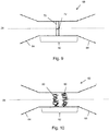
- FIG 9 shows another embodiment, in which there is provided within the lumen of the flexible connector 62 a valve element 60, which may be a disk valve having a slit 72 therein.
- the valve 70 can be opened by pushing a guide wire through the slit 72 and will then close again by its own resiliency once the guide wire has been removed.
- the valve element 70 can be made of any suitable known material.
- Figure 10 shows another embodiment, in which there is provided one or more sets of thrombogenic fibres 80 within the lumen 28 of the flexible connector element 62.
- the thrombogenic fibres 80 can be adhered or bonded to the flexible connecter element 62.
- the thrombogenic fibres can be wrapped around turns of the coil 62 so as to be held thereby.
- FIG. 11 this shows the implantable medical device 10, 30, 40 within a blood vessel 90 of a patient and in particular at a point of curvature of the vessel 90.
- the wide ends 16 of the filter device engage with the vessel walls and are generally disposed perpendicular to the axis 92 of the vessel, thereby ensuring patency to the vessel wall and that there are no leaks of blood around the edges of the material capture elements of the device.
- This is achievable as a result of the flexible connector element 62 which, as can be seen in Figure 11 , can curve with the curvature of the lumen.
- the restoring force and the resistance to curvature of the flexible connector element 62 is substantially less than the strength of the vessel 90 so as not to impart a great straightening force on the vessel.
- the device therefore, has the advantage of a double ended medical device, such as a double ended filter or occluder, but without the disadvantage of known devices of this type.
- the entirety of the frame of the structure forming the implantable medical device may be made of a shape memory material such as Nitinol, that is the material capture elements as well as the connecting element.
- the elements of the structure could be made of a spring material such as spring steel or the like. Any combination of materials could be used for the different parts of the structure, for instance a first material for the material capture elements and a different material for the connecting element.
Landscapes
- Health & Medical Sciences (AREA)
- Life Sciences & Earth Sciences (AREA)
- Surgery (AREA)
- Animal Behavior & Ethology (AREA)
- Veterinary Medicine (AREA)
- Vascular Medicine (AREA)
- Public Health (AREA)
- Engineering & Computer Science (AREA)
- Biomedical Technology (AREA)
- Heart & Thoracic Surgery (AREA)
- General Health & Medical Sciences (AREA)
- Molecular Biology (AREA)
- Medical Informatics (AREA)
- Nuclear Medicine, Radiotherapy & Molecular Imaging (AREA)
- Reproductive Health (AREA)
- Cardiology (AREA)
- Oral & Maxillofacial Surgery (AREA)
- Transplantation (AREA)
- Surgical Instruments (AREA)
- Prostheses (AREA)
Claims (11)
- Implantierbare medizinische Vorrichtung (10), die aufweist:erste und zweite Materialabfangelemente, die jeweils ein weites Ende und ein schmales Ende aufweisen, wobei die ersten und zweiten Materialabfangelemente (12, 14) so angeordnet sind, dass ihren schmalen Enden (18) einander zugewandt sind und ihre weiten Enden in entgegengesetzte Richtungen zeigen;ein flexibles Verbindungselement, das einsetzbar ist, in einem gebogenen Zustand zu bleiben, wobei das flexible Verbindungselement mit den schmalen Enden (18) der ersten und zweiten Materialabfangelemente (12, 14) verbunden ist, um eine unitäre Vorrichtung mit den ersten und zweiten Materialabfangelementen zu bilden; wobei das flexible Verbindungselement (26) für Hindurchtreten von Fluid verschließbar ist, wobei das Verbindungselement (26) eine Wendel ist, wobei die Wendel ein Lumen (28) darin bereitstellt, wobei ein Verschlusselement (68, 70, 80) bereitgestellt ist, um den Durchgang von Fluid durch die Wendel zu verschließen.
- Implantierbare medizinische Vorrichtung (10) gemäß Anspruch 1, wobei die Wendel (26) ein gewendelter Draht oder eine helikal geschnittene Kanüle ist.
- Implantierbare medizinische Vorrichtung (10) gemäß Anspruch 1 oder 2, wobei das Verschlusselement ein Ventil (68, 70) ist, wobei das Ventil öffenbar ist, um Durchtreten durch das Lumen (28) der Wendel zu erlauben, und schließbar ist, um Durchtreten durch das Lumen zu blockieren.
- Implantierbare medizinische Vorrichtung (10) gemäß Anspruch 3, die ein zweites Verschlusselement aufweist, das in dem anderen von den ersten und zweiten Materialabfangelementen (12, 14) angeordnet ist.
- Implantierbare medizinische Vorrichtung (10) gemäß Anspruch 1, wobei das Verschlusselement aus einem Teil der Wendel gebildet ist, der ein schmales Mittelstück (36) ist, das das Lumen (28) darin verschließt oder im Wesentlichen verschließt.
- Implantierbare medizinische Vorrichtung (10) gemäß Anspruch 5, wobei das Mittelstück (36) durch Verdrillen zu öffnen ist, wodurch das Verschlusselement als Ventil wirken kann, das, wenn offen, Durchtreten durch das Lumen (28) erlaubt und, wenn geschlossen, Durchtreten durch das Lumen (28) blockiert.
- Implantierbare medizinische Vorrichtung (10) gemäß Anspruch 1 oder 2, wobei das Verschlusselement in der Form von thrombogenen Fasern (80) vorliegt, die so angeordnet sind, dass sie sich quer durch das Lumen (28) der Wendel erstrecken.
- Implantierbare medizinische Vorrichtung (10) gemäß einem der vorstehenden Ansprüche, wobei die ersten und zweiten Materialabfangelemente (12, 14) jeweils einen Rahmen aufweisen, wobei das Verbindungselement an dem Rahmen befestigt ist.
- Implantierbare medizinische Vorrichtung (10) gemäß Anspruch 8, wobei die Rahmen der ersten und zweiten Materialabfangelemente (12, 14) ein Stück in dem Verbindungselement (26) sind.
- Implantierbare medizinische Vorrichtung (10) gemäß einem der vorstehenden Ansprüche, wobei die Vorrichtung ein Okkluder ist und die Materialabfangelemente (12, 14) undurchlässig für Fluid sind.
- Implantierbare medizinische Vorrichtung (10) gemäß einem der Ansprüche 1 bis 9, wobei die Vorrichtung ein Filter ist und die Materialabfangelemente (12, 14) fluidporös sind.
Applications Claiming Priority (1)
| Application Number | Priority Date | Filing Date | Title |
|---|---|---|---|
| GB1400391.7A GB2522034B (en) | 2014-01-10 | 2014-01-10 | Implantable medical device with flexible connection |
Publications (2)
| Publication Number | Publication Date |
|---|---|
| EP2893902A1 EP2893902A1 (de) | 2015-07-15 |
| EP2893902B1 true EP2893902B1 (de) | 2021-06-30 |
Family
ID=50191129
Family Applications (1)
| Application Number | Title | Priority Date | Filing Date |
|---|---|---|---|
| EP14275260.9A Active EP2893902B1 (de) | 2014-01-10 | 2014-12-17 | Implantierbare medizinische Vorrichtung mit flexibler Verbindung |
Country Status (3)
| Country | Link |
|---|---|
| US (1) | US10463376B2 (de) |
| EP (1) | EP2893902B1 (de) |
| GB (1) | GB2522034B (de) |
Cited By (1)
| Publication number | Priority date | Publication date | Assignee | Title |
|---|---|---|---|---|
| US12521202B2 (en) | 2019-11-29 | 2026-01-13 | Somatex Medical Technologies Gmbh | Marking element for marking tissue |
Families Citing this family (20)
| Publication number | Priority date | Publication date | Assignee | Title |
|---|---|---|---|---|
| WO2011064782A2 (en) | 2009-11-30 | 2011-06-03 | Endospan Ltd. | Multi-component stent-graft system for implantation in a blood vessel with multiple branches |
| US9597204B2 (en) * | 2011-12-04 | 2017-03-21 | Endospan Ltd. | Branched stent-graft system |
| WO2013171730A1 (en) | 2012-05-15 | 2013-11-21 | Endospan Ltd. | Stent-graft with fixation elements that are radially confined for delivery |
| EP3957276A1 (de) | 2012-05-31 | 2022-02-23 | Javelin Medical Ltd. | Vorrichtung zum embolieschutz |
| US9993360B2 (en) | 2013-01-08 | 2018-06-12 | Endospan Ltd. | Minimization of stent-graft migration during implantation |
| ES2895968T3 (es) | 2013-01-18 | 2022-02-23 | Javelin Medical Ltd | Implantes de monofilamento y sistemas para suministro de los mismos |
| CN105208969B (zh) | 2013-03-11 | 2017-10-20 | 恩多斯潘有限公司 | 用于主动脉夹层的多组件支架移植物系统 |
| WO2015075708A1 (en) | 2013-11-19 | 2015-05-28 | Endospan Ltd. | Stent system with radial-expansion locking |
| US9592110B1 (en) | 2013-12-06 | 2017-03-14 | Javelin Medical, Ltd. | Systems and methods for implant delivery |
| EP3068339B1 (de) | 2014-12-18 | 2017-11-01 | Endospan Ltd. | Endovaskuläre stentprothese mit einem ermüdungsbeständigen lateralrohr |
| US10231815B2 (en) * | 2015-01-16 | 2019-03-19 | Cook Medical Technologies Llc | Spiral bird's nest filter |
| EP4732782A2 (de) | 2016-06-03 | 2026-04-29 | SOMATEX Medical Technologies GmbH | Markierungsvorrichtung und implantationssystem |
| US20170367710A1 (en) * | 2016-06-24 | 2017-12-28 | Cook Medical Technologies Llc | Double sided occlusive device |
| JP7062303B2 (ja) | 2016-10-14 | 2022-05-06 | インセプタス メディカル, エルエルシー | 編組マシンおよび使用方法 |
| ES2967415T3 (es) | 2016-10-21 | 2024-04-30 | Javelin Medical Ltd | Dispositivos de protección embólica |
| EP4082473A3 (de) | 2016-11-23 | 2023-01-25 | Hologic, Inc. | Biopsiestellenmarker |
| CN110573092B (zh) * | 2017-02-24 | 2023-04-18 | 因赛普特斯医学有限责任公司 | 血管阻塞装置和方法 |
| US11885051B2 (en) | 2017-10-14 | 2024-01-30 | Inceptus Medical, Llc | Braiding machine and methods of use |
| AU2019457740B2 (en) * | 2019-07-22 | 2022-08-25 | Clearstream Technologies Limited | An embolization device for promoting clot formation in a bodily lumen and a method of assembling said embolization device |
| US20220403123A1 (en) * | 2019-11-18 | 2022-12-22 | Sappi Netherlands Services B.V. | Non-corroding fiber-reinforced polymer compositions |
Family Cites Families (18)
| Publication number | Priority date | Publication date | Assignee | Title |
|---|---|---|---|---|
| US5626605A (en) | 1991-12-30 | 1997-05-06 | Scimed Life Systems, Inc. | Thrombosis filter |
| US6117157A (en) * | 1994-03-18 | 2000-09-12 | Cook Incorporated | Helical embolization coil |
| EP0793457B2 (de) * | 1994-04-06 | 2006-04-12 | WILLIAM COOK EUROPE ApS | Eine medizinische vorrichtung zur implantation in das gefässystem eines patienten |
| GB9716497D0 (en) * | 1997-08-05 | 1997-10-08 | Bridport Gundry Plc | Occlusion device |
| FR2813518B1 (fr) * | 2000-09-04 | 2002-10-31 | Claude Mialhe | Dispositif d'occlusion vasculaire, appareil et procede d'utilisation |
| US20070129755A1 (en) * | 2005-12-05 | 2007-06-07 | Ovalis, Inc. | Clip-based systems and methods for treating septal defects |
| JP4398244B2 (ja) * | 2001-10-04 | 2010-01-13 | ネオヴァスク メディカル リミテッド | 流量減少インプラント |
| FR2847150B1 (fr) * | 2002-11-15 | 2005-01-21 | Claude Mialhe | Dispositif occlusif a destination medicale ou chirurgicale |
| US9545300B2 (en) * | 2004-12-22 | 2017-01-17 | W. L. Gore & Associates, Inc. | Filament-wound implantable devices |
| DE102005032308A1 (de) | 2005-07-11 | 2007-01-18 | Campus Gmbh & Co. Kg | Endovaskulares Implantat für den Verschluss eines Blutgefäßes |
| US8285677B2 (en) * | 2006-06-30 | 2012-10-09 | International Business Machines Corporation | Method and apparatus for propagating tables while preserving cyclic foreign key relationships |
| US20080051830A1 (en) * | 2006-08-24 | 2008-02-28 | Boston Scientific Scimed, Inc. | Occluding device and method |
| WO2008115922A1 (en) | 2007-03-19 | 2008-09-25 | Michael Brenzel | Methods and apparatus for occlusion of body lumens |
| EP2282684B1 (de) * | 2008-04-03 | 2016-06-15 | Cook Medical Technologies LLC | Okklusionsvorrichtung |
| US20110184439A1 (en) * | 2008-05-09 | 2011-07-28 | University Of Pittsburgh-Of The Commonwealth System Of Higher Education | Biological Matrix for Cardiac Repair |
| US20110144689A1 (en) * | 2009-12-15 | 2011-06-16 | Med Institute, Inc. | Occlusion Device |
| WO2012092377A1 (en) | 2010-12-30 | 2012-07-05 | Claret Medical, Inc. | Intravascular blood filters and methods of use |
| US11911258B2 (en) * | 2013-06-26 | 2024-02-27 | W. L. Gore & Associates, Inc. | Space filling devices |
-
2014
- 2014-01-10 GB GB1400391.7A patent/GB2522034B/en not_active Expired - Fee Related
- 2014-12-17 EP EP14275260.9A patent/EP2893902B1/de active Active
-
2015
- 2015-01-09 US US14/593,545 patent/US10463376B2/en active Active
Non-Patent Citations (1)
| Title |
|---|
| None * |
Cited By (1)
| Publication number | Priority date | Publication date | Assignee | Title |
|---|---|---|---|---|
| US12521202B2 (en) | 2019-11-29 | 2026-01-13 | Somatex Medical Technologies Gmbh | Marking element for marking tissue |
Also Published As
| Publication number | Publication date |
|---|---|
| US10463376B2 (en) | 2019-11-05 |
| GB201400391D0 (en) | 2014-02-26 |
| US20150196301A1 (en) | 2015-07-16 |
| EP2893902A1 (de) | 2015-07-15 |
| GB2522034A (en) | 2015-07-15 |
| GB2522034B (en) | 2015-12-02 |
Similar Documents
| Publication | Publication Date | Title |
|---|---|---|
| US10463376B2 (en) | Implantable medical device with flexible connection | |
| US10398443B2 (en) | Implantable medical device with lumen constriction | |
| EP2939614B1 (de) | Implantierbare medizinische Vorrichtung mit verdrehtem Element | |
| AU2018253740B2 (en) | Braid expansion ring with markers | |
| EP3295901A1 (de) | Expansionsring für geflochtene stents | |
| CA2593817A1 (en) | Stent retrieval member and devices and methods for retrieving or repositioning a stent | |
| US10123805B2 (en) | Space filling devices | |
| US10022128B2 (en) | Cone expanding collapsible medical device | |
| CN112220585A (zh) | 具有插置支撑构件的下腔静脉过滤器收回系统 | |
| EP2997933B1 (de) | Implantierbare vaskuläre schnappverschlussvorrichtung | |
| EP3072552A1 (de) | Medizinische vorrichtung mit vorspannelement | |
| EP2113229A1 (de) | Stent und behandlungsvorrichtung für röhrenförmige organe | |
| US20170156844A1 (en) | Implantable flow diverter | |
| US9788932B2 (en) | Vascular filter | |
| US11547396B2 (en) | Devices and methods for securing medical devices within an anatomy | |
| EP3011937B1 (de) | Längliche medizinische vorrichtung | |
| KR20200081260A (ko) | 하나 이상의 확장 링을 갖는 편조 스텐트 시스템 | |
| US20140330303A1 (en) | Vascular plug | |
| CN211534995U (zh) | 一种栓塞保护装置 | |
| US10010399B2 (en) | Low profile intraluminal filters | |
| US10143544B2 (en) | Low profile intraluminal medical devices | |
| EP4066784A1 (de) | Embolieschutzvorrichtung |
Legal Events
| Date | Code | Title | Description |
|---|---|---|---|
| PUAI | Public reference made under article 153(3) epc to a published international application that has entered the european phase |
Free format text: ORIGINAL CODE: 0009012 |
|
| 17P | Request for examination filed |
Effective date: 20141217 |
|
| AK | Designated contracting states |
Kind code of ref document: A1 Designated state(s): AL AT BE BG CH CY CZ DE DK EE ES FI FR GB GR HR HU IE IS IT LI LT LU LV MC MK MT NL NO PL PT RO RS SE SI SK SM TR |
|
| AX | Request for extension of the european patent |
Extension state: BA ME |
|
| RIN1 | Information on inventor provided before grant (corrected) |
Inventor name: BOEDEWADT, TUE Inventor name: HANSEN, CHRISTINA |
|
| R17P | Request for examination filed (corrected) |
Effective date: 20151001 |
|
| RBV | Designated contracting states (corrected) |
Designated state(s): AL AT BE BG CH CY CZ DE DK EE ES FI FR GB GR HR HU IE IS IT LI LT LU LV MC MK MT NL NO PL PT RO RS SE SI SK SM TR |
|
| STAA | Information on the status of an ep patent application or granted ep patent |
Free format text: STATUS: EXAMINATION IS IN PROGRESS |
|
| 17Q | First examination report despatched |
Effective date: 20181008 |
|
| GRAP | Despatch of communication of intention to grant a patent |
Free format text: ORIGINAL CODE: EPIDOSNIGR1 |
|
| STAA | Information on the status of an ep patent application or granted ep patent |
Free format text: STATUS: GRANT OF PATENT IS INTENDED |
|
| GRAJ | Information related to disapproval of communication of intention to grant by the applicant or resumption of examination proceedings by the epo deleted |
Free format text: ORIGINAL CODE: EPIDOSDIGR1 |
|
| STAA | Information on the status of an ep patent application or granted ep patent |
Free format text: STATUS: EXAMINATION IS IN PROGRESS |
|
| INTG | Intention to grant announced |
Effective date: 20201103 |
|
| INTC | Intention to grant announced (deleted) | ||
| GRAP | Despatch of communication of intention to grant a patent |
Free format text: ORIGINAL CODE: EPIDOSNIGR1 |
|
| STAA | Information on the status of an ep patent application or granted ep patent |
Free format text: STATUS: GRANT OF PATENT IS INTENDED |
|
| INTG | Intention to grant announced |
Effective date: 20210119 |
|
| GRAS | Grant fee paid |
Free format text: ORIGINAL CODE: EPIDOSNIGR3 |
|
| GRAA | (expected) grant |
Free format text: ORIGINAL CODE: 0009210 |
|
| STAA | Information on the status of an ep patent application or granted ep patent |
Free format text: STATUS: THE PATENT HAS BEEN GRANTED |
|
| AK | Designated contracting states |
Kind code of ref document: B1 Designated state(s): AL AT BE BG CH CY CZ DE DK EE ES FI FR GB GR HR HU IE IS IT LI LT LU LV MC MK MT NL NO PL PT RO RS SE SI SK SM TR |
|
| REG | Reference to a national code |
Ref country code: GB Ref legal event code: FG4D Ref country code: CH Ref legal event code: EP |
|
| REG | Reference to a national code |
Ref country code: AT Ref legal event code: REF Ref document number: 1405652 Country of ref document: AT Kind code of ref document: T Effective date: 20210715 |
|
| REG | Reference to a national code |
Ref country code: DE Ref legal event code: R096 Ref document number: 602014078412 Country of ref document: DE |
|
| REG | Reference to a national code |
Ref country code: IE Ref legal event code: FG4D |
|
| REG | Reference to a national code |
Ref country code: LT Ref legal event code: MG9D |
|
| PG25 | Lapsed in a contracting state [announced via postgrant information from national office to epo] |
Ref country code: FI Free format text: LAPSE BECAUSE OF FAILURE TO SUBMIT A TRANSLATION OF THE DESCRIPTION OR TO PAY THE FEE WITHIN THE PRESCRIBED TIME-LIMIT Effective date: 20210630 Ref country code: BG Free format text: LAPSE BECAUSE OF FAILURE TO SUBMIT A TRANSLATION OF THE DESCRIPTION OR TO PAY THE FEE WITHIN THE PRESCRIBED TIME-LIMIT Effective date: 20210930 Ref country code: HR Free format text: LAPSE BECAUSE OF FAILURE TO SUBMIT A TRANSLATION OF THE DESCRIPTION OR TO PAY THE FEE WITHIN THE PRESCRIBED TIME-LIMIT Effective date: 20210630 |
|
| REG | Reference to a national code |
Ref country code: NL Ref legal event code: MP Effective date: 20210630 |
|
| REG | Reference to a national code |
Ref country code: AT Ref legal event code: MK05 Ref document number: 1405652 Country of ref document: AT Kind code of ref document: T Effective date: 20210630 |
|
| PG25 | Lapsed in a contracting state [announced via postgrant information from national office to epo] |
Ref country code: LV Free format text: LAPSE BECAUSE OF FAILURE TO SUBMIT A TRANSLATION OF THE DESCRIPTION OR TO PAY THE FEE WITHIN THE PRESCRIBED TIME-LIMIT Effective date: 20210630 Ref country code: GR Free format text: LAPSE BECAUSE OF FAILURE TO SUBMIT A TRANSLATION OF THE DESCRIPTION OR TO PAY THE FEE WITHIN THE PRESCRIBED TIME-LIMIT Effective date: 20211001 Ref country code: SE Free format text: LAPSE BECAUSE OF FAILURE TO SUBMIT A TRANSLATION OF THE DESCRIPTION OR TO PAY THE FEE WITHIN THE PRESCRIBED TIME-LIMIT Effective date: 20210630 Ref country code: RS Free format text: LAPSE BECAUSE OF FAILURE TO SUBMIT A TRANSLATION OF THE DESCRIPTION OR TO PAY THE FEE WITHIN THE PRESCRIBED TIME-LIMIT Effective date: 20210630 Ref country code: NO Free format text: LAPSE BECAUSE OF FAILURE TO SUBMIT A TRANSLATION OF THE DESCRIPTION OR TO PAY THE FEE WITHIN THE PRESCRIBED TIME-LIMIT Effective date: 20210930 |
|
| PG25 | Lapsed in a contracting state [announced via postgrant information from national office to epo] |
Ref country code: PT Free format text: LAPSE BECAUSE OF FAILURE TO SUBMIT A TRANSLATION OF THE DESCRIPTION OR TO PAY THE FEE WITHIN THE PRESCRIBED TIME-LIMIT Effective date: 20211102 Ref country code: RO Free format text: LAPSE BECAUSE OF FAILURE TO SUBMIT A TRANSLATION OF THE DESCRIPTION OR TO PAY THE FEE WITHIN THE PRESCRIBED TIME-LIMIT Effective date: 20210630 Ref country code: NL Free format text: LAPSE BECAUSE OF FAILURE TO SUBMIT A TRANSLATION OF THE DESCRIPTION OR TO PAY THE FEE WITHIN THE PRESCRIBED TIME-LIMIT Effective date: 20210630 Ref country code: ES Free format text: LAPSE BECAUSE OF FAILURE TO SUBMIT A TRANSLATION OF THE DESCRIPTION OR TO PAY THE FEE WITHIN THE PRESCRIBED TIME-LIMIT Effective date: 20210630 Ref country code: AT Free format text: LAPSE BECAUSE OF FAILURE TO SUBMIT A TRANSLATION OF THE DESCRIPTION OR TO PAY THE FEE WITHIN THE PRESCRIBED TIME-LIMIT Effective date: 20210630 Ref country code: SM Free format text: LAPSE BECAUSE OF FAILURE TO SUBMIT A TRANSLATION OF THE DESCRIPTION OR TO PAY THE FEE WITHIN THE PRESCRIBED TIME-LIMIT Effective date: 20210630 Ref country code: SK Free format text: LAPSE BECAUSE OF FAILURE TO SUBMIT A TRANSLATION OF THE DESCRIPTION OR TO PAY THE FEE WITHIN THE PRESCRIBED TIME-LIMIT Effective date: 20210630 Ref country code: EE Free format text: LAPSE BECAUSE OF FAILURE TO SUBMIT A TRANSLATION OF THE DESCRIPTION OR TO PAY THE FEE WITHIN THE PRESCRIBED TIME-LIMIT Effective date: 20210630 Ref country code: CZ Free format text: LAPSE BECAUSE OF FAILURE TO SUBMIT A TRANSLATION OF THE DESCRIPTION OR TO PAY THE FEE WITHIN THE PRESCRIBED TIME-LIMIT Effective date: 20210630 |
|
| PG25 | Lapsed in a contracting state [announced via postgrant information from national office to epo] |
Ref country code: PL Free format text: LAPSE BECAUSE OF FAILURE TO SUBMIT A TRANSLATION OF THE DESCRIPTION OR TO PAY THE FEE WITHIN THE PRESCRIBED TIME-LIMIT Effective date: 20210630 |
|
| REG | Reference to a national code |
Ref country code: DE Ref legal event code: R097 Ref document number: 602014078412 Country of ref document: DE |
|
| PG25 | Lapsed in a contracting state [announced via postgrant information from national office to epo] |
Ref country code: DK Free format text: LAPSE BECAUSE OF FAILURE TO SUBMIT A TRANSLATION OF THE DESCRIPTION OR TO PAY THE FEE WITHIN THE PRESCRIBED TIME-LIMIT Effective date: 20210630 |
|
| PLBE | No opposition filed within time limit |
Free format text: ORIGINAL CODE: 0009261 |
|
| STAA | Information on the status of an ep patent application or granted ep patent |
Free format text: STATUS: NO OPPOSITION FILED WITHIN TIME LIMIT |
|
| PG25 | Lapsed in a contracting state [announced via postgrant information from national office to epo] |
Ref country code: AL Free format text: LAPSE BECAUSE OF FAILURE TO SUBMIT A TRANSLATION OF THE DESCRIPTION OR TO PAY THE FEE WITHIN THE PRESCRIBED TIME-LIMIT Effective date: 20210630 |
|
| 26N | No opposition filed |
Effective date: 20220331 |
|
| PG25 | Lapsed in a contracting state [announced via postgrant information from national office to epo] |
Ref country code: MC Free format text: LAPSE BECAUSE OF FAILURE TO SUBMIT A TRANSLATION OF THE DESCRIPTION OR TO PAY THE FEE WITHIN THE PRESCRIBED TIME-LIMIT Effective date: 20210630 Ref country code: IT Free format text: LAPSE BECAUSE OF FAILURE TO SUBMIT A TRANSLATION OF THE DESCRIPTION OR TO PAY THE FEE WITHIN THE PRESCRIBED TIME-LIMIT Effective date: 20210630 |
|
| REG | Reference to a national code |
Ref country code: CH Ref legal event code: PL |
|
| REG | Reference to a national code |
Ref country code: BE Ref legal event code: MM Effective date: 20211231 |
|
| PG25 | Lapsed in a contracting state [announced via postgrant information from national office to epo] |
Ref country code: LU Free format text: LAPSE BECAUSE OF NON-PAYMENT OF DUE FEES Effective date: 20211217 |
|
| PG25 | Lapsed in a contracting state [announced via postgrant information from national office to epo] |
Ref country code: FR Free format text: LAPSE BECAUSE OF NON-PAYMENT OF DUE FEES Effective date: 20211231 Ref country code: BE Free format text: LAPSE BECAUSE OF NON-PAYMENT OF DUE FEES Effective date: 20211231 |
|
| PG25 | Lapsed in a contracting state [announced via postgrant information from national office to epo] |
Ref country code: LI Free format text: LAPSE BECAUSE OF NON-PAYMENT OF DUE FEES Effective date: 20211231 Ref country code: CH Free format text: LAPSE BECAUSE OF NON-PAYMENT OF DUE FEES Effective date: 20211231 |
|
| PG25 | Lapsed in a contracting state [announced via postgrant information from national office to epo] |
Ref country code: LT Free format text: LAPSE BECAUSE OF FAILURE TO SUBMIT A TRANSLATION OF THE DESCRIPTION OR TO PAY THE FEE WITHIN THE PRESCRIBED TIME-LIMIT Effective date: 20210630 |
|
| PG25 | Lapsed in a contracting state [announced via postgrant information from national office to epo] |
Ref country code: HU Free format text: LAPSE BECAUSE OF FAILURE TO SUBMIT A TRANSLATION OF THE DESCRIPTION OR TO PAY THE FEE WITHIN THE PRESCRIBED TIME-LIMIT; INVALID AB INITIO Effective date: 20141217 |
|
| PG25 | Lapsed in a contracting state [announced via postgrant information from national office to epo] |
Ref country code: CY Free format text: LAPSE BECAUSE OF FAILURE TO SUBMIT A TRANSLATION OF THE DESCRIPTION OR TO PAY THE FEE WITHIN THE PRESCRIBED TIME-LIMIT Effective date: 20210630 |
|
| P01 | Opt-out of the competence of the unified patent court (upc) registered |
Effective date: 20230602 |
|
| PG25 | Lapsed in a contracting state [announced via postgrant information from national office to epo] |
Ref country code: MK Free format text: LAPSE BECAUSE OF FAILURE TO SUBMIT A TRANSLATION OF THE DESCRIPTION OR TO PAY THE FEE WITHIN THE PRESCRIBED TIME-LIMIT Effective date: 20210630 |
|
| PG25 | Lapsed in a contracting state [announced via postgrant information from national office to epo] |
Ref country code: MT Free format text: LAPSE BECAUSE OF FAILURE TO SUBMIT A TRANSLATION OF THE DESCRIPTION OR TO PAY THE FEE WITHIN THE PRESCRIBED TIME-LIMIT Effective date: 20210630 |
|
| PG25 | Lapsed in a contracting state [announced via postgrant information from national office to epo] |
Ref country code: TR Free format text: LAPSE BECAUSE OF FAILURE TO SUBMIT A TRANSLATION OF THE DESCRIPTION OR TO PAY THE FEE WITHIN THE PRESCRIBED TIME-LIMIT Effective date: 20210630 |
|
| PGFP | Annual fee paid to national office [announced via postgrant information from national office to epo] |
Ref country code: GB Payment date: 20251223 Year of fee payment: 12 |
|
| PGFP | Annual fee paid to national office [announced via postgrant information from national office to epo] |
Ref country code: IE Payment date: 20251218 Year of fee payment: 12 |
|
| PGFP | Annual fee paid to national office [announced via postgrant information from national office to epo] |
Ref country code: DE Payment date: 20251229 Year of fee payment: 12 |