EP2893067B1 - Apparatus for presenting weft threads - Google Patents
Apparatus for presenting weft threads Download PDFInfo
- Publication number
- EP2893067B1 EP2893067B1 EP13756134.6A EP13756134A EP2893067B1 EP 2893067 B1 EP2893067 B1 EP 2893067B1 EP 13756134 A EP13756134 A EP 13756134A EP 2893067 B1 EP2893067 B1 EP 2893067B1
- Authority
- EP
- European Patent Office
- Prior art keywords
- presenting
- crank
- connecting rod
- frame
- presenting element
- Prior art date
- Legal status (The legal status is an assumption and is not a legal conclusion. Google has not performed a legal analysis and makes no representation as to the accuracy of the status listed.)
- Active
Links
Images


Classifications
-
- D—TEXTILES; PAPER
- D03—WEAVING
- D03D—WOVEN FABRICS; METHODS OF WEAVING; LOOMS
- D03D47/00—Looms in which bulk supply of weft does not pass through shed, e.g. shuttleless looms, gripper shuttle looms, dummy shuttle looms
- D03D47/34—Handling the weft between bulk storage and weft-inserting means
- D03D47/38—Weft pattern mechanisms
Definitions
- the invention relates to an apparatus for presenting weft threads to an insertion device of a weaving machine, wherein at least one presenting element, such as a needle, is mounted displaceable in longitudinal direction between a rest position and a feed position by means of a crank mechanism.
- An apparatus which selects and presents weft threads to an insertion device of a weaving machine is shown for example in EP 0 598 264 B1 .
- This apparatus comprises at least one needle for presenting a weft thread to the insertion device and driving means with an individual crank and an individual drive motor for selectively moving the needle between a rest position and a feed position, wherein the needle is directly connected to the crank and wherein guiding means are provided at each needle for guiding the needle in the movement between the rest and feed positions and for compensating transverse movements of the crank.
- JP 10-212641 A and CN 2628554 Y each show an apparatus which selects and presents weft threads to an insertion device of a weaving machine using a crank, wherein a connecting rod is provided between a needle presenting the weft thread and the crank, and the needle is mounted displaceable in longitudinal direction.
- an apparatus for presenting weft threads to an insertion device of a weaving machine comprising at least one presenting element mounted displaceable in the longitudinal direction between a rest position and a feed position and a crank mechanism with a crank and a connecting rod for driving the at least one presenting element, wherein the at least one presenting element is connected to the connecting rod, wherein the connecting rod is supported by a guiding element, and wherein the guiding element is able to compensate transverse forces exerted on the connecting rod by the crank, so that the presenting element is only subjected to forces in its longitudinal direction.
- the presenting element is connected to the connecting rod by a pivot, wherein the pivot is formed at the height of the guiding element.
- a sleeve or an axle of the pivot is formed integrally with the guiding element. Due to this, the number of elements to be moved and thereby the inertia of the crank mechanism is minimized.
- the presenting element comprises a thread receiving end, wherein the connecting rod is attached to the opposite end of the presenting element.
- the thread receiving element is designed as a thread eye or thread clamp for receiving the weft thread to be presented.
- a frame is provided, wherein the presenting element and the connecting rod are mounted to the frame.
- the frame may comprise a plurality of frame parts. In preferred embodiments, only one frame part is provided, allowing for a simple design with a high stiffness.
- the frame is provided with a guide groove extending in the longitudinal direction of the presenting element, wherein the guiding element is slidingly disposed in said guide groove.
- the at least one presenting element is mounted displaceable to the frame by at least one bearing point, preferably by two bearing points.
- the at least one bearing point comprises a bearing bush for receiving the respective presenting element and a support on which the bearing bush is attached to the frame.
- the support on which the bearing bush is attached to the frame preferably comprises an elastic rubber socket. Due to the mounting of the presenting elements with “elastic" supports, the presenting elements are allowed to move within defined limits with the weft thread.
- the bearing bush comprises a pin received rotatably by the support for allowing the presenting elements to move with the weft thread.
- the frame is provided with a recess for accommodating the crank in order to allow a movement of the crank.
- walls of the recess may be used as end stops for the movement of the crank.
- each presenting element together with the respective frame and the respective crank mechanism forms one module.
- the apparatus can comprises a plurality of presenting elements depending on the number of weft yarns required for a certain fabric. Providing a module simplifies a matching of the number of presenting elements to the requirements of a certain fabric. Moreover, the module may be exchanged as a unit in case of defect.
- a drive motor is assigned to the crank mechanism, such that the crank is driven by its own drive motor.
- the drive motor is preferably integrated in the module.
- the motor is arranged to drive the crank to and fro over a defined angular range.
- the motor may also be arranged to rotate in one direction, wherein the presenting element is moved in longitudinal direction only, as the direction of rotation does not influence the linear movement direction of the presenting element.
- the connecting rod is attached to the crank on the outer side of the crank.
- the presenting element is a needle with a thread eye.
- the presenting elements are arranged with yarn clamps such as are known in the art.
- Figs. 1 to 3 show a single module 1 of an apparatus for presenting weft threads, more particularly an apparatus for presenting weft threads to a gripper of a gripper weaving machine.
- the apparatus comprises a plurality of identical modules 1.
- the modules for example, can be disposed as the modules in EP 0 598 264 A1 .
- Each module 1 comprises a presenting element 2, wherein in Figs. 1 and 4 the presenting element 2 is in a rest position, in Figs. 3 and 6 the presenting element 2 is in a feed position, and in Figs. 2 and 5 the presenting element 2 is in an intermediate position.
- the presenting element 2 is designed as a needle, one end 41 of which includes a thread eye 20 for guiding a weft thread (not shown).
- the different modules 1 of an apparatus in one embodiment are arranged in one plane.
- the presenting elements in one embodiment are directed to one common point, as known from EP 0 362 089 A1 .
- the presenting elements are arranged in a so called fan arrangement, as known from EP 0 638 677 A1 .
- the presenting elements are arranged in a plane and the modules can be arranged in two rows as known from EP 0 598 264 A1 .
- Each module 1 further comprises a crank mechanism 3 with a crank 30 and a connecting rod 31, a drive motor 4 with a shaft 40 and a frame 5 on which the presenting element 2, the crank 30, the connecting rod 31 and the drive motor 4 are mounted.
- the drive motor 4 is connected via the crank mechanism 3 to the presenting element 2.
- the connecting rod 31 is pivotably attached to the crank 30 by a pivot 32.
- the connecting rod 31 is attached to the crank 30 on the outer side of the crank 30, i.e. on the side facing away from drive motor 4.
- the presenting element 2 is attached to the connecting rod 31 at the end 42 opposite the thread eye 20 by a pivot 60. Further, the presenting element 2 is mounted to the frame 5 by two bearing points 7 for a longitudinal movement of the presenting element 2.
- the bearing points 7 each comprise a bearing bush 70, wherein the presenting element 2 passes through the bearing bush 70, and a support 71 by which the bearing bush 70 is attached to the frame 5, for example by means of an elastic or a non-elastic pin 72.
- the pin 72 is arranged rotatable in the frame 5 at a fixed position by using a bush 73.
- the supports 71 provided for of the presenting elements 2 are designed as elastic rubber sockets, as a result of which the presenting elements 2 are elastically supported in the transverse direction. Hence, the presenting elements 2 are allowed to move within limits defined by the elasticity of the support 71. This movement allows that the presenting element 2 can move somewhat under the influence of forces exerted by a weft thread at the height of the thread eye 20 and/or forces that arise by supporting the presenting element 2 in three points.
- the crank 30 is fixed to the shaft 40 of the drive motor 4.
- the drive motor 4 is arranged to a back side of the frame 5 by suitable fixing means such as screws.
- the frame 5 is provided with a recess 50.
- the recess 50 is formed by a base and two steps 52 projecting from the base.
- the motor can move to and fro over an angular range of approximately 180°. In use, the range may be chosen smaller for example an angular range between approximately 90° and approximately 170° may be sufficient for an intended application.
- the maximum angle of rotation of the crank 30 is bounded by the walls of the recess 50.
- the shape and/or size of the recess 50 may be chosen suitably. In the embodiment shown, the shape is chosen in such a way that for the rest and feed positions, shown in Figs. 1 , 4 and Figs. 3 , 6 , respectively, the crank 30, the connecting rod 31 and the presenting element 2 are aligned.
- a drive motor 4 may be provided that rotates in one direction, as the direction of rotation does not influence the linear movement direction of the presenting element 2. In this case no recess 50 will be provided.
- the frame 5 is provided with a guide groove 51 extending in the longitudinal direction of the presenting element 2, in which guide groove 51 the guiding element 6 is slidingly arranged.
- the material and/or the size of the guiding element 6 and the guide groove 51 are chosen for ensuring only a limited friction upon the sliding movement and to avoid wear.
- the guide groove 51 is for example fully open, this means extends through the frame 5, in order to prevent that weaving dust accumulates at the height of the guide groove 51.
- the guiding element 6, the guide groove 51 and the bearing points 7 are aligned with the presenting element 2, i.e. are arranged in a plane passing through the axis of the presenting element 2. Due to the elasticity of the supports 71 comparatively large tolerances are allowed. Further, due to the additional guiding element 6, one of the bearing points 7 may be omitted, for example the bearing point 7 near the guiding element 6.
- the presenting elements 2 Upon rotation of the crank 30, the presenting elements 2 move along their longitudinal direction, wherein the stroke of the presenting elements 2 depends on the length of the crank 30.
- the crank 30 may be chosen comparatively large allowing for a large stroke, wherein forces in transverse direction are compensated by the guiding element 6.
- the guiding element 6 comprises a cylinder shaped bottom part 62, that is arranged rotatable and slidingly displaceable in the guide groove 51, and a connecting part 63 that is one-piece with the bottom part 62.
- the connecting part 63 is one-piece with or connected to the connecting rod 31.
- a pivot 60 is formed between the presenting element 2 and the guiding element 6, which pivot 60 allows a mutual rotation of the connecting rod 31 and the presenting element 2.
- the pivot 60 comprises an axle 65 attached to the presenting element 2 and a sleeve 64 received by the connecting part 63. De sleeve can also be replaced by a bearing.
- the bottom part 62 can consist of a guide block to which a pivot 60 is arranged, which pivot 60 allows a mutual rotation of the connecting rod 31 and the presenting element 2.
- the masses of the parts to be moved by the drive motor 4, namely of the crank 30, the connecting rod 31, the presenting element 2 and the guiding element 6 are comparatively small.
- the crank 30 is for example also provided with a clearance 33.
- the base surface of the frame 5 is tapering from the area of the drive motor 4 toward the end 41. This shape is advantageous for an arrangement of the module 1 in an apparatus, but not mandatory.
Landscapes
- Engineering & Computer Science (AREA)
- Textile Engineering (AREA)
- Looms (AREA)
Description
- The invention relates to an apparatus for presenting weft threads to an insertion device of a weaving machine, wherein at least one presenting element, such as a needle, is mounted displaceable in longitudinal direction between a rest position and a feed position by means of a crank mechanism.
- An apparatus which selects and presents weft threads to an insertion device of a weaving machine is shown for example in
EP 0 598 264 B1 . This apparatus comprises at least one needle for presenting a weft thread to the insertion device and driving means with an individual crank and an individual drive motor for selectively moving the needle between a rest position and a feed position, wherein the needle is directly connected to the crank and wherein guiding means are provided at each needle for guiding the needle in the movement between the rest and feed positions and for compensating transverse movements of the crank. -
JP 10-212641 A CN 2628554 Y each show an apparatus which selects and presents weft threads to an insertion device of a weaving machine using a crank, wherein a connecting rod is provided between a needle presenting the weft thread and the crank, and the needle is mounted displaceable in longitudinal direction. - It is an object of the invention to provide an apparatus of the type described above, wherein a large stroke of the presenting elements is possible at high speeds.
- This object is solved by an apparatus for presenting weft threads to an insertion device of a weaving machine, comprising at least one presenting element mounted displaceable in the longitudinal direction between a rest position and a feed position and a crank mechanism with a crank and a connecting rod for driving the at least one presenting element, wherein the at least one presenting element is connected to the connecting rod, wherein the connecting rod is supported by a guiding element, and wherein the guiding element is able to compensate transverse forces exerted on the connecting rod by the crank, so that the presenting element is only subjected to forces in its longitudinal direction.
- By providing the guiding element for supporting the connecting rod, perpendicular forces, that occur when the connecting rod is driven by the crank, are compensated by the guiding element and not transferred to the presenting element. Thereby, frictional forces in bearing points of the presenting element are avoided and the presenting element may be moved with high speeds over a large distance in its longitudinal direction.
- In one embodiment, the presenting element is connected to the connecting rod by a pivot, wherein the pivot is formed at the height of the guiding element. In particular, a sleeve or an axle of the pivot is formed integrally with the guiding element. Due to this, the number of elements to be moved and thereby the inertia of the crank mechanism is minimized.
- According to another embodiment, the presenting element comprises a thread receiving end, wherein the connecting rod is attached to the opposite end of the presenting element. The thread receiving element is designed as a thread eye or thread clamp for receiving the weft thread to be presented.
- In a preferred embodiment, a frame is provided, wherein the presenting element and the connecting rod are mounted to the frame. The frame may comprise a plurality of frame parts. In preferred embodiments, only one frame part is provided, allowing for a simple design with a high stiffness.
- According to one embodiment, the frame is provided with a guide groove extending in the longitudinal direction of the presenting element, wherein the guiding element is slidingly disposed in said guide groove.
- In preferred embodiments, the at least one presenting element is mounted displaceable to the frame by at least one bearing point, preferably by two bearing points. Preferably, the at least one bearing point comprises a bearing bush for receiving the respective presenting element and a support on which the bearing bush is attached to the frame. The support on which the bearing bush is attached to the frame preferably comprises an elastic rubber socket. Due to the mounting of the presenting elements with "elastic" supports, the presenting elements are allowed to move within defined limits with the weft thread. In addition or as an alternative, the bearing bush comprises a pin received rotatably by the support for allowing the presenting elements to move with the weft thread.
- According to another embodiment, the frame is provided with a recess for accommodating the crank in order to allow a movement of the crank. Thereby, walls of the recess may be used as end stops for the movement of the crank.
- In another embodiment, each presenting element together with the respective frame and the respective crank mechanism forms one module. The apparatus can comprises a plurality of presenting elements depending on the number of weft yarns required for a certain fabric. Providing a module simplifies a matching of the number of presenting elements to the requirements of a certain fabric. Moreover, the module may be exchanged as a unit in case of defect.
- According to a preferred embodiment, a drive motor is assigned to the crank mechanism, such that the crank is driven by its own drive motor.
- The drive motor is preferably integrated in the module. In one embodiment, the motor is arranged to drive the crank to and fro over a defined angular range. The motor may also be arranged to rotate in one direction, wherein the presenting element is moved in longitudinal direction only, as the direction of rotation does not influence the linear movement direction of the presenting element.
- In a preferred embodiment, the connecting rod is attached to the crank on the outer side of the crank. With this arrangement, a height of the module perpendicular to the plane of the crank can be minimized.
- In preferred embodiments, the presenting element is a needle with a thread eye. In another embodiment, the presenting elements are arranged with yarn clamps such as are known in the art.
- Preferred embodiments are defined in the dependent claims and the drawings.
- In the following, an embodiment of the invention will be described in detail based on several schematic drawings in which
-
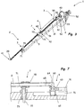
Figs. 1 - 3
are perspective schematic views of an apparatus for selecting and presenting weft threads with a presenting element according to the invention, wherein the presenting element is shown in three different positions. -
Figs. 4 - 6
are schematic front views corresponding to that ofFigs. 1 to 3 . -
Fig. 7
shows a cross section at the height of the guiding element and a bearing point. -
Figs. 1 to 3 show asingle module 1 of an apparatus for presenting weft threads, more particularly an apparatus for presenting weft threads to a gripper of a gripper weaving machine. In preferred embodiments, the apparatus comprises a plurality ofidentical modules 1. In such an apparatus for selecting and presenting weft threads the modules, for example, can be disposed as the modules inEP 0 598 264 A1 . - Each
module 1 comprises a presentingelement 2, wherein inFigs. 1 and4 the presentingelement 2 is in a rest position, inFigs. 3 and6 the presentingelement 2 is in a feed position, and inFigs. 2 and5 the presentingelement 2 is in an intermediate position. In the embodiment shown the presentingelement 2 is designed as a needle, oneend 41 of which includes athread eye 20 for guiding a weft thread (not shown). - The
different modules 1 of an apparatus in one embodiment are arranged in one plane. When arranged in one plane, the presenting elements in one embodiment are directed to one common point, as known fromEP 0 362 089 A1 . In other embodiments, the presenting elements are arranged in a so called fan arrangement, as known fromEP 0 638 677 A1 . In a preferred embodiment the presenting elements are arranged in a plane and the modules can be arranged in two rows as known fromEP 0 598 264 A1 . - Each
module 1 further comprises acrank mechanism 3 with acrank 30 and aconnecting rod 31, adrive motor 4 with ashaft 40 and aframe 5 on which the presentingelement 2, thecrank 30, the connectingrod 31 and thedrive motor 4 are mounted. Thedrive motor 4 is connected via thecrank mechanism 3 to the presentingelement 2. - The connecting
rod 31 is pivotably attached to thecrank 30 by apivot 32. The connectingrod 31 is attached to thecrank 30 on the outer side of thecrank 30, i.e. on the side facing away fromdrive motor 4. - The presenting
element 2 is attached to the connectingrod 31 at theend 42 opposite thethread eye 20 by apivot 60. Further, the presentingelement 2 is mounted to theframe 5 by twobearing points 7 for a longitudinal movement of the presentingelement 2. As shown inFig. 7 , thebearing points 7 each comprise abearing bush 70, wherein the presentingelement 2 passes through thebearing bush 70, and asupport 71 by which thebearing bush 70 is attached to theframe 5, for example by means of an elastic or anon-elastic pin 72. In the embodiment shown, thepin 72 is arranged rotatable in theframe 5 at a fixed position by using abush 73. - The
supports 71 provided for of the presentingelements 2 are designed as elastic rubber sockets, as a result of which the presentingelements 2 are elastically supported in the transverse direction. Hence, the presentingelements 2 are allowed to move within limits defined by the elasticity of thesupport 71. This movement allows that the presentingelement 2 can move somewhat under the influence of forces exerted by a weft thread at the height of thethread eye 20 and/or forces that arise by supporting the presentingelement 2 in three points. - The
crank 30 is fixed to theshaft 40 of thedrive motor 4. Thedrive motor 4 is arranged to a back side of theframe 5 by suitable fixing means such as screws. For allowing a movement of thecrank 30, in the embodiment shown theframe 5 is provided with arecess 50. Therecess 50 is formed by a base and twosteps 52 projecting from the base. According to an embodiment the motor can move to and fro over an angular range of approximately 180°. In use, the range may be chosen smaller for example an angular range between approximately 90° and approximately 170° may be sufficient for an intended application. In the embodiment shown, the maximum angle of rotation of thecrank 30 is bounded by the walls of therecess 50. The shape and/or size of therecess 50 may be chosen suitably. In the embodiment shown, the shape is chosen in such a way that for the rest and feed positions, shown inFigs. 1 ,4 andFigs. 3 ,6 , respectively, thecrank 30, the connectingrod 31 and the presentingelement 2 are aligned. - According to a variant, a
drive motor 4 may be provided that rotates in one direction, as the direction of rotation does not influence the linear movement direction of the presentingelement 2. In this case norecess 50 will be provided. - Due to the movement of the
crank 30, forces are acting on the connectingrod 31 in a direction transverse to the longitudinal direction of the presentingelement 2. For compensating these transverse forces of thecrank 30, the connectingrod 31 is supported by a guidingelement 6. The guidingelement 6 is able to compensate the transverse forces, so that the presentingelement 2 is only subjected to forces in its longitudinal direction, also referred to as length direction. - In the embodiment shown, the
frame 5 is provided with aguide groove 51 extending in the longitudinal direction of the presentingelement 2, in which guidegroove 51 the guidingelement 6 is slidingly arranged. The material and/or the size of the guidingelement 6 and theguide groove 51 are chosen for ensuring only a limited friction upon the sliding movement and to avoid wear. Theguide groove 51 is for example fully open, this means extends through theframe 5, in order to prevent that weaving dust accumulates at the height of theguide groove 51. - The guiding
element 6, theguide groove 51 and the bearing points 7 are aligned with the presentingelement 2, i.e. are arranged in a plane passing through the axis of the presentingelement 2. Due to the elasticity of thesupports 71 comparatively large tolerances are allowed. Further, due to theadditional guiding element 6, one of the bearing points 7 may be omitted, for example thebearing point 7 near the guidingelement 6. - Upon rotation of the
crank 30, the presentingelements 2 move along their longitudinal direction, wherein the stroke of the presentingelements 2 depends on the length of thecrank 30. The crank 30 may be chosen comparatively large allowing for a large stroke, wherein forces in transverse direction are compensated by the guidingelement 6. - As shown in
Fig. 7 , in the shown embodiment the guidingelement 6 comprises a cylinder shapedbottom part 62, that is arranged rotatable and slidingly displaceable in theguide groove 51, and a connectingpart 63 that is one-piece with thebottom part 62. The connectingpart 63 is one-piece with or connected to the connectingrod 31. Apivot 60 is formed between the presentingelement 2 and the guidingelement 6, whichpivot 60 allows a mutual rotation of the connectingrod 31 and the presentingelement 2. In the embodiment shown, thepivot 60 comprises anaxle 65 attached to the presentingelement 2 and asleeve 64 received by the connectingpart 63. De sleeve can also be replaced by a bearing. - According to a variant not shown the
bottom part 62 can consist of a guide block to which apivot 60 is arranged, whichpivot 60 allows a mutual rotation of the connectingrod 31 and the presentingelement 2. - The masses of the parts to be moved by the
drive motor 4, namely of thecrank 30, the connectingrod 31, the presentingelement 2 and the guidingelement 6 are comparatively small. For this purpose, thecrank 30 is for example also provided with aclearance 33. As a result of the small masses, only relatively low inertias need to be overcome to move the presentingelement 2. Consequently, higher operational speeds and/or the use of relatively low-power drive motors 4 are possible. - As shown in the Figs, the base surface of the
frame 5 is tapering from the area of thedrive motor 4 toward theend 41. This shape is advantageous for an arrangement of themodule 1 in an apparatus, but not mandatory. - Having thus described preferred embodiments of the invention and variants and modifications thereof in sufficient detail enable the person skilled in the art to make and to use the invention based on the above description and accompanying drawings, it is nevertheless intended that the invention is not be limited by the description or illustrations, but rather that it be defined solely by the appended claims.
Claims (14)
- Apparatus for presenting weft threads to an insertion device of a weaving machine, comprising at least one presenting element (2) mounted displaceable in the longitudinal direction between a rest position and a feed position and a crank mechanism (3) with a crank (30) and a connecting rod (31) for driving the at least one presenting element (2), wherein the at least one presenting element (2) is connected to the connecting rod (31), characterized in that the connecting rod (31) is supported by a guiding element (6), wherein the guiding element (6) is able to compensate transverse forces exerted on the connecting rod (31) by the crank (30), so that the presenting element (2) is only subjected to forces in its longitudinal direction
- Apparatus according to claim 1, characterized in that the presenting element (2) is connected to the connecting rod (31) by a pivot (60), wherein the pivot (60) is formed at the guiding element (6).
- Apparatus according to claim 1 or 2, characterized in that the presenting element (2) comprises a thread receiving end (41), wherein the connecting rod (31) is attached to the end (42) of the presenting element (2) opposite to the thread receiving end (41).
- Apparatus according to any one of claims 1, 2 or 3, characterized in that a frame (5) is provided, wherein the presenting element (2) and the connecting rod (31) are mounted to the frame (5).
- Apparatus according to claim 4, characterized in that the frame (5) is provided with a guide groove (51) extending in the longitudinal direction of the presenting element (2), wherein the guiding element (6) is slidingly arranged in said guide groove (51).
- Apparatus according to claim 4 or 5, characterized in that the at least one presenting element (2) is mounted displaceably to the frame (5) by at least one bearing point (7), preferably by two bearing points (7).
- Apparatus according to claim 6, characterized in that the at least one bearing point (7) comprises a bearing bush (70) for receiving the respective presenting element (2) and a support (71) by which the bearing bush (70) is attached to the frame (5).
- Apparatus according to claim 7, characterized in that the support (71) by which the bearing bush (70) is attached to the frame (5) comprises an elastic rubber socket.
- Apparatus according to claim 7 or 8, characterized in that the support (71) comprises a rotatable received pin (72).
- Apparatus according to any one of claims 4 to 9, characterized in that the frame (5) is provided with a recess (50) for accommodating the crank (30) in order to allow a movement of the crank (30).
- Apparatus according to any one of claims 4 to 10, characterized in that each presenting element (2) together with the respective frame (5) and the respective crank mechanism (3) forms one module (1).
- Apparatus according to any one of claims 1 to 11, characterized in that a drive motor (4) is assigned to the crank mechanism (3), such that the crank (30) is driven by its own drive motor (4).
- Apparatus according to any one of claims 1 to 12, characterized in that the connecting rod (31) is attached to the crank (30) on the outer side of the crank (30).
- Apparatus according to any one of claims 1 to 13, characterized in that the presenting element (2) is a needle with a thread eye (20).
Applications Claiming Priority (2)
| Application Number | Priority Date | Filing Date | Title |
|---|---|---|---|
| BE2012/0584A BE1021341B1 (en) | 2012-09-06 | 2012-09-06 | APPARATUS FOR PRESENTING IMPORTS WIRES TO A FEEDER OF A WEAVING MACHINE |
| PCT/EP2013/067953 WO2014037282A2 (en) | 2012-09-06 | 2013-08-29 | Apparatus for presenting weft threads |
Publications (2)
| Publication Number | Publication Date |
|---|---|
| EP2893067A2 EP2893067A2 (en) | 2015-07-15 |
| EP2893067B1 true EP2893067B1 (en) | 2019-04-03 |
Family
ID=47074512
Family Applications (1)
| Application Number | Title | Priority Date | Filing Date |
|---|---|---|---|
| EP13756134.6A Active EP2893067B1 (en) | 2012-09-06 | 2013-08-29 | Apparatus for presenting weft threads |
Country Status (5)
| Country | Link |
|---|---|
| EP (1) | EP2893067B1 (en) |
| CN (1) | CN104704152B (en) |
| BE (1) | BE1021341B1 (en) |
| TR (1) | TR201909215T4 (en) |
| WO (1) | WO2014037282A2 (en) |
Cited By (1)
| Publication number | Priority date | Publication date | Assignee | Title |
|---|---|---|---|---|
| EP4310233A1 (en) | 2022-07-19 | 2024-01-24 | Picanol | Device for selecting and presenting weft threads |
Families Citing this family (1)
| Publication number | Priority date | Publication date | Assignee | Title |
|---|---|---|---|---|
| EP3714088B1 (en) * | 2017-11-22 | 2025-06-04 | Kurkute, Sanjay | Weaving machine with single needle rotary weft presenter |
Family Cites Families (6)
| Publication number | Priority date | Publication date | Assignee | Title |
|---|---|---|---|---|
| FR2636979B1 (en) | 1988-09-27 | 1990-11-02 | Marsande Petrus | WEFT YARN FEEDING DEVICE FOR NON-SHUTTLE WEAVING |
| BE1006347A3 (en) | 1992-11-16 | 1994-07-26 | Picanol Nv | DEVICE FOR PRESENTING weft threads in weaving machines. |
| DE4325905C1 (en) * | 1993-08-02 | 1994-10-06 | Dornier Gmbh Lindauer | Device for feeding weft threads to a weft-thread insertion member in weaving machines |
| JPH10212641A (en) * | 1997-01-20 | 1998-08-11 | Tsudakoma Corp | Weft selecting apparatus for rapier weaving machine |
| CN2647881Y (en) * | 2003-07-03 | 2004-10-13 | 中国纺织科学研究院 | At wefting-insertion weft selecting and inserting means of rapier loom |
| CN2628554Y (en) * | 2003-07-29 | 2004-07-28 | 彭长林 | High-speed electronic weft selecting device for rapier loom |
-
2012
- 2012-09-06 BE BE2012/0584A patent/BE1021341B1/en not_active IP Right Cessation
-
2013
- 2013-08-29 WO PCT/EP2013/067953 patent/WO2014037282A2/en not_active Ceased
- 2013-08-29 EP EP13756134.6A patent/EP2893067B1/en active Active
- 2013-08-29 CN CN201380046564.2A patent/CN104704152B/en active Active
- 2013-08-29 TR TR2019/09215T patent/TR201909215T4/en unknown
Non-Patent Citations (1)
| Title |
|---|
| None * |
Cited By (3)
| Publication number | Priority date | Publication date | Assignee | Title |
|---|---|---|---|---|
| EP4310233A1 (en) | 2022-07-19 | 2024-01-24 | Picanol | Device for selecting and presenting weft threads |
| WO2024017541A1 (en) | 2022-07-19 | 2024-01-25 | Picanol | Device for selecting and presenting weft threads |
| BE1030686A1 (en) | 2022-07-19 | 2024-01-26 | Picanol | Device for selecting and presenting weft threads |
Also Published As
| Publication number | Publication date |
|---|---|
| WO2014037282A3 (en) | 2014-05-30 |
| CN104704152B (en) | 2016-09-28 |
| CN104704152A (en) | 2015-06-10 |
| EP2893067A2 (en) | 2015-07-15 |
| BE1021341B1 (en) | 2015-11-05 |
| WO2014037282A2 (en) | 2014-03-13 |
| TR201909215T4 (en) | 2019-07-22 |
Similar Documents
| Publication | Publication Date | Title |
|---|---|---|
| US5241842A (en) | Warp knitting machine with individually movable yarn guides arranged on a guide bar | |
| US5513676A (en) | Lifting knife type shedding device for a weaving machine | |
| CN107020257A (en) | Unilateral beam type self-regulation dust cleaning brush system | |
| WO2014037282A2 (en) | Apparatus for presenting weft threads | |
| JP5532495B2 (en) | Device for forming Reno ears | |
| EP0896075B1 (en) | Weft yarn presenting device for weaving looms | |
| CN105593425B (en) | Shuttle embroidery machine | |
| CN201261824Y (en) | Novel active loose warp driving device | |
| CN101215755B (en) | Density triangular driving mechanism for computer flat knitting machine | |
| US20020036022A1 (en) | Device for guiding the knife-supporting beams in a jacquard machine | |
| CN103741344A (en) | Fuzzing control device for towel machine and working method thereof | |
| KR20220152930A (en) | Selvage yarn shedding apparatus of loom | |
| KR200419600Y1 (en) | Guide hook drive of crochet knitting machine | |
| CN107964721B (en) | Warp feed in looms | |
| EP4310233A1 (en) | Device for selecting and presenting weft threads | |
| EP1302580A2 (en) | Device for supporting the temple and associated cover in a terry cloth loom with movable bench | |
| KR102753297B1 (en) | Guide bar drive of a warp knitting machine | |
| CN210826669U (en) | Needle pitch limiting mechanism | |
| EP2920345B1 (en) | Clamping device and weaving machine with a clamping device | |
| CN2718000Y (en) | Improved motor-driving gripper opening device | |
| CN224047646U (en) | Needle bar coiling mechanism of knitting machine | |
| CN211972628U (en) | Warp beam frame for carbon fiber weaving | |
| JP2000282343A (en) | Ear assembly device | |
| CN210826576U (en) | Hosiery machine feed carrier | |
| CN111348479B (en) | Novel tilting mechanism |
Legal Events
| Date | Code | Title | Description |
|---|---|---|---|
| PUAI | Public reference made under article 153(3) epc to a published international application that has entered the european phase |
Free format text: ORIGINAL CODE: 0009012 |
|
| 17P | Request for examination filed |
Effective date: 20150109 |
|
| AK | Designated contracting states |
Kind code of ref document: A2 Designated state(s): AL AT BE BG CH CY CZ DE DK EE ES FI FR GB GR HR HU IE IS IT LI LT LU LV MC MK MT NL NO PL PT RO RS SE SI SK SM TR |
|
| AX | Request for extension of the european patent |
Extension state: BA ME |
|
| DAX | Request for extension of the european patent (deleted) | ||
| GRAP | Despatch of communication of intention to grant a patent |
Free format text: ORIGINAL CODE: EPIDOSNIGR1 |
|
| STAA | Information on the status of an ep patent application or granted ep patent |
Free format text: STATUS: GRANT OF PATENT IS INTENDED |
|
| INTG | Intention to grant announced |
Effective date: 20181127 |
|
| GRAS | Grant fee paid |
Free format text: ORIGINAL CODE: EPIDOSNIGR3 |
|
| GRAA | (expected) grant |
Free format text: ORIGINAL CODE: 0009210 |
|
| STAA | Information on the status of an ep patent application or granted ep patent |
Free format text: STATUS: THE PATENT HAS BEEN GRANTED |
|
| AK | Designated contracting states |
Kind code of ref document: B1 Designated state(s): AL AT BE BG CH CY CZ DE DK EE ES FI FR GB GR HR HU IE IS IT LI LT LU LV MC MK MT NL NO PL PT RO RS SE SI SK SM TR |
|
| REG | Reference to a national code |
Ref country code: GB Ref legal event code: FG4D |
|
| REG | Reference to a national code |
Ref country code: CH Ref legal event code: EP Ref country code: AT Ref legal event code: REF Ref document number: 1115867 Country of ref document: AT Kind code of ref document: T Effective date: 20190415 |
|
| REG | Reference to a national code |
Ref country code: DE Ref legal event code: R096 Ref document number: 602013053320 Country of ref document: DE |
|
| REG | Reference to a national code |
Ref country code: IE Ref legal event code: FG4D |
|
| REG | Reference to a national code |
Ref country code: NL Ref legal event code: MP Effective date: 20190403 |
|
| REG | Reference to a national code |
Ref country code: LT Ref legal event code: MG4D |
|
| REG | Reference to a national code |
Ref country code: AT Ref legal event code: MK05 Ref document number: 1115867 Country of ref document: AT Kind code of ref document: T Effective date: 20190403 |
|
| PG25 | Lapsed in a contracting state [announced via postgrant information from national office to epo] |
Ref country code: NL Free format text: LAPSE BECAUSE OF FAILURE TO SUBMIT A TRANSLATION OF THE DESCRIPTION OR TO PAY THE FEE WITHIN THE PRESCRIBED TIME-LIMIT Effective date: 20190403 |
|
| PG25 | Lapsed in a contracting state [announced via postgrant information from national office to epo] |
Ref country code: PT Free format text: LAPSE BECAUSE OF FAILURE TO SUBMIT A TRANSLATION OF THE DESCRIPTION OR TO PAY THE FEE WITHIN THE PRESCRIBED TIME-LIMIT Effective date: 20190803 Ref country code: ES Free format text: LAPSE BECAUSE OF FAILURE TO SUBMIT A TRANSLATION OF THE DESCRIPTION OR TO PAY THE FEE WITHIN THE PRESCRIBED TIME-LIMIT Effective date: 20190403 Ref country code: HR Free format text: LAPSE BECAUSE OF FAILURE TO SUBMIT A TRANSLATION OF THE DESCRIPTION OR TO PAY THE FEE WITHIN THE PRESCRIBED TIME-LIMIT Effective date: 20190403 Ref country code: SE Free format text: LAPSE BECAUSE OF FAILURE TO SUBMIT A TRANSLATION OF THE DESCRIPTION OR TO PAY THE FEE WITHIN THE PRESCRIBED TIME-LIMIT Effective date: 20190403 Ref country code: AL Free format text: LAPSE BECAUSE OF FAILURE TO SUBMIT A TRANSLATION OF THE DESCRIPTION OR TO PAY THE FEE WITHIN THE PRESCRIBED TIME-LIMIT Effective date: 20190403 Ref country code: FI Free format text: LAPSE BECAUSE OF FAILURE TO SUBMIT A TRANSLATION OF THE DESCRIPTION OR TO PAY THE FEE WITHIN THE PRESCRIBED TIME-LIMIT Effective date: 20190403 Ref country code: NO Free format text: LAPSE BECAUSE OF FAILURE TO SUBMIT A TRANSLATION OF THE DESCRIPTION OR TO PAY THE FEE WITHIN THE PRESCRIBED TIME-LIMIT Effective date: 20190703 Ref country code: CZ Free format text: LAPSE BECAUSE OF FAILURE TO SUBMIT A TRANSLATION OF THE DESCRIPTION OR TO PAY THE FEE WITHIN THE PRESCRIBED TIME-LIMIT Effective date: 20190403 Ref country code: LT Free format text: LAPSE BECAUSE OF FAILURE TO SUBMIT A TRANSLATION OF THE DESCRIPTION OR TO PAY THE FEE WITHIN THE PRESCRIBED TIME-LIMIT Effective date: 20190403 |
|
| PG25 | Lapsed in a contracting state [announced via postgrant information from national office to epo] |
Ref country code: RS Free format text: LAPSE BECAUSE OF FAILURE TO SUBMIT A TRANSLATION OF THE DESCRIPTION OR TO PAY THE FEE WITHIN THE PRESCRIBED TIME-LIMIT Effective date: 20190403 Ref country code: LV Free format text: LAPSE BECAUSE OF FAILURE TO SUBMIT A TRANSLATION OF THE DESCRIPTION OR TO PAY THE FEE WITHIN THE PRESCRIBED TIME-LIMIT Effective date: 20190403 Ref country code: BG Free format text: LAPSE BECAUSE OF FAILURE TO SUBMIT A TRANSLATION OF THE DESCRIPTION OR TO PAY THE FEE WITHIN THE PRESCRIBED TIME-LIMIT Effective date: 20190703 Ref country code: GR Free format text: LAPSE BECAUSE OF FAILURE TO SUBMIT A TRANSLATION OF THE DESCRIPTION OR TO PAY THE FEE WITHIN THE PRESCRIBED TIME-LIMIT Effective date: 20190704 Ref country code: PL Free format text: LAPSE BECAUSE OF FAILURE TO SUBMIT A TRANSLATION OF THE DESCRIPTION OR TO PAY THE FEE WITHIN THE PRESCRIBED TIME-LIMIT Effective date: 20190403 |
|
| PG25 | Lapsed in a contracting state [announced via postgrant information from national office to epo] |
Ref country code: IS Free format text: LAPSE BECAUSE OF FAILURE TO SUBMIT A TRANSLATION OF THE DESCRIPTION OR TO PAY THE FEE WITHIN THE PRESCRIBED TIME-LIMIT Effective date: 20190803 Ref country code: AT Free format text: LAPSE BECAUSE OF FAILURE TO SUBMIT A TRANSLATION OF THE DESCRIPTION OR TO PAY THE FEE WITHIN THE PRESCRIBED TIME-LIMIT Effective date: 20190403 |
|
| REG | Reference to a national code |
Ref country code: DE Ref legal event code: R097 Ref document number: 602013053320 Country of ref document: DE |
|
| PG25 | Lapsed in a contracting state [announced via postgrant information from national office to epo] |
Ref country code: EE Free format text: LAPSE BECAUSE OF FAILURE TO SUBMIT A TRANSLATION OF THE DESCRIPTION OR TO PAY THE FEE WITHIN THE PRESCRIBED TIME-LIMIT Effective date: 20190403 Ref country code: DK Free format text: LAPSE BECAUSE OF FAILURE TO SUBMIT A TRANSLATION OF THE DESCRIPTION OR TO PAY THE FEE WITHIN THE PRESCRIBED TIME-LIMIT Effective date: 20190403 Ref country code: SK Free format text: LAPSE BECAUSE OF FAILURE TO SUBMIT A TRANSLATION OF THE DESCRIPTION OR TO PAY THE FEE WITHIN THE PRESCRIBED TIME-LIMIT Effective date: 20190403 Ref country code: RO Free format text: LAPSE BECAUSE OF FAILURE TO SUBMIT A TRANSLATION OF THE DESCRIPTION OR TO PAY THE FEE WITHIN THE PRESCRIBED TIME-LIMIT Effective date: 20190403 |
|
| PLBE | No opposition filed within time limit |
Free format text: ORIGINAL CODE: 0009261 |
|
| STAA | Information on the status of an ep patent application or granted ep patent |
Free format text: STATUS: NO OPPOSITION FILED WITHIN TIME LIMIT |
|
| PG25 | Lapsed in a contracting state [announced via postgrant information from national office to epo] |
Ref country code: SM Free format text: LAPSE BECAUSE OF FAILURE TO SUBMIT A TRANSLATION OF THE DESCRIPTION OR TO PAY THE FEE WITHIN THE PRESCRIBED TIME-LIMIT Effective date: 20190403 |
|
| 26N | No opposition filed |
Effective date: 20200106 |
|
| GBPC | Gb: european patent ceased through non-payment of renewal fee |
Effective date: 20190829 |
|
| PG25 | Lapsed in a contracting state [announced via postgrant information from national office to epo] |
Ref country code: SI Free format text: LAPSE BECAUSE OF FAILURE TO SUBMIT A TRANSLATION OF THE DESCRIPTION OR TO PAY THE FEE WITHIN THE PRESCRIBED TIME-LIMIT Effective date: 20190403 Ref country code: LI Free format text: LAPSE BECAUSE OF NON-PAYMENT OF DUE FEES Effective date: 20190831 Ref country code: LU Free format text: LAPSE BECAUSE OF NON-PAYMENT OF DUE FEES Effective date: 20190829 Ref country code: MC Free format text: LAPSE BECAUSE OF FAILURE TO SUBMIT A TRANSLATION OF THE DESCRIPTION OR TO PAY THE FEE WITHIN THE PRESCRIBED TIME-LIMIT Effective date: 20190403 Ref country code: CH Free format text: LAPSE BECAUSE OF NON-PAYMENT OF DUE FEES Effective date: 20190831 |
|
| PG25 | Lapsed in a contracting state [announced via postgrant information from national office to epo] |
Ref country code: FR Free format text: LAPSE BECAUSE OF NON-PAYMENT OF DUE FEES Effective date: 20190831 Ref country code: IE Free format text: LAPSE BECAUSE OF NON-PAYMENT OF DUE FEES Effective date: 20190829 |
|
| PG25 | Lapsed in a contracting state [announced via postgrant information from national office to epo] |
Ref country code: GB Free format text: LAPSE BECAUSE OF NON-PAYMENT OF DUE FEES Effective date: 20190829 |
|
| PG25 | Lapsed in a contracting state [announced via postgrant information from national office to epo] |
Ref country code: CY Free format text: LAPSE BECAUSE OF FAILURE TO SUBMIT A TRANSLATION OF THE DESCRIPTION OR TO PAY THE FEE WITHIN THE PRESCRIBED TIME-LIMIT Effective date: 20190403 |
|
| PG25 | Lapsed in a contracting state [announced via postgrant information from national office to epo] |
Ref country code: MT Free format text: LAPSE BECAUSE OF FAILURE TO SUBMIT A TRANSLATION OF THE DESCRIPTION OR TO PAY THE FEE WITHIN THE PRESCRIBED TIME-LIMIT Effective date: 20190403 Ref country code: HU Free format text: LAPSE BECAUSE OF FAILURE TO SUBMIT A TRANSLATION OF THE DESCRIPTION OR TO PAY THE FEE WITHIN THE PRESCRIBED TIME-LIMIT; INVALID AB INITIO Effective date: 20130829 |
|
| PG25 | Lapsed in a contracting state [announced via postgrant information from national office to epo] |
Ref country code: MK Free format text: LAPSE BECAUSE OF FAILURE TO SUBMIT A TRANSLATION OF THE DESCRIPTION OR TO PAY THE FEE WITHIN THE PRESCRIBED TIME-LIMIT Effective date: 20190403 |
|
| P01 | Opt-out of the competence of the unified patent court (upc) registered |
Effective date: 20230519 |
|
| PGFP | Annual fee paid to national office [announced via postgrant information from national office to epo] |
Ref country code: DE Payment date: 20250819 Year of fee payment: 13 |
|
| PGFP | Annual fee paid to national office [announced via postgrant information from national office to epo] |
Ref country code: TR Payment date: 20250821 Year of fee payment: 13 Ref country code: IT Payment date: 20250829 Year of fee payment: 13 |
|
| PGFP | Annual fee paid to national office [announced via postgrant information from national office to epo] |
Ref country code: BE Payment date: 20250626 Year of fee payment: 13 |