EP2892105A1 - Test jig - Google Patents
Test jig Download PDFInfo
- Publication number
- EP2892105A1 EP2892105A1 EP14783759.5A EP14783759A EP2892105A1 EP 2892105 A1 EP2892105 A1 EP 2892105A1 EP 14783759 A EP14783759 A EP 14783759A EP 2892105 A1 EP2892105 A1 EP 2892105A1
- Authority
- EP
- European Patent Office
- Prior art keywords
- fixing member
- electrode lead
- main body
- jig
- insertion part
- Prior art date
- Legal status (The legal status is an assumption and is not a legal conclusion. Google has not performed a legal analysis and makes no representation as to the accuracy of the status listed.)
- Granted
Links
Images




Classifications
-
- H—ELECTRICITY
- H01—ELECTRIC ELEMENTS
- H01M—PROCESSES OR MEANS, e.g. BATTERIES, FOR THE DIRECT CONVERSION OF CHEMICAL ENERGY INTO ELECTRICAL ENERGY
- H01M10/00—Secondary cells; Manufacture thereof
- H01M10/42—Methods or arrangements for servicing or maintenance of secondary cells or secondary half-cells
- H01M10/4285—Testing apparatus
-
- B—PERFORMING OPERATIONS; TRANSPORTING
- B25—HAND TOOLS; PORTABLE POWER-DRIVEN TOOLS; MANIPULATORS
- B25B—TOOLS OR BENCH DEVICES NOT OTHERWISE PROVIDED FOR, FOR FASTENING, CONNECTING, DISENGAGING, OR HOLDING
- B25B11/00—Work holders not covered by any preceding group in the subclass, e.g. magnetic work holders, vacuum work holders
-
- G—PHYSICS
- G01—MEASURING; TESTING
- G01N—INVESTIGATING OR ANALYSING MATERIALS BY DETERMINING THEIR CHEMICAL OR PHYSICAL PROPERTIES
- G01N3/00—Investigating strength properties of solid materials by application of mechanical stress
- G01N3/02—Details
- G01N3/04—Chucks
-
- H—ELECTRICITY
- H01—ELECTRIC ELEMENTS
- H01M—PROCESSES OR MEANS, e.g. BATTERIES, FOR THE DIRECT CONVERSION OF CHEMICAL ENERGY INTO ELECTRICAL ENERGY
- H01M10/00—Secondary cells; Manufacture thereof
- H01M10/42—Methods or arrangements for servicing or maintenance of secondary cells or secondary half-cells
- H01M10/48—Accumulators combined with arrangements for measuring, testing or indicating the condition of cells, e.g. the level or density of the electrolyte
-
- G—PHYSICS
- G01—MEASURING; TESTING
- G01N—INVESTIGATING OR ANALYSING MATERIALS BY DETERMINING THEIR CHEMICAL OR PHYSICAL PROPERTIES
- G01N3/00—Investigating strength properties of solid materials by application of mechanical stress
- G01N3/08—Investigating strength properties of solid materials by application of mechanical stress by applying steady tensile or compressive forces
-
- H—ELECTRICITY
- H01—ELECTRIC ELEMENTS
- H01M—PROCESSES OR MEANS, e.g. BATTERIES, FOR THE DIRECT CONVERSION OF CHEMICAL ENERGY INTO ELECTRICAL ENERGY
- H01M50/00—Constructional details or processes of manufacture of the non-active parts of electrochemical cells other than fuel cells, e.g. hybrid cells
- H01M50/10—Primary casings; Jackets or wrappings
- H01M50/172—Arrangements of electric connectors penetrating the casing
- H01M50/174—Arrangements of electric connectors penetrating the casing adapted for the shape of the cells
- H01M50/176—Arrangements of electric connectors penetrating the casing adapted for the shape of the cells for prismatic or rectangular cells
-
- H—ELECTRICITY
- H01—ELECTRIC ELEMENTS
- H01M—PROCESSES OR MEANS, e.g. BATTERIES, FOR THE DIRECT CONVERSION OF CHEMICAL ENERGY INTO ELECTRICAL ENERGY
- H01M50/00—Constructional details or processes of manufacture of the non-active parts of electrochemical cells other than fuel cells, e.g. hybrid cells
- H01M50/50—Current conducting connections for cells or batteries
- H01M50/531—Electrode connections inside a battery casing
- H01M50/536—Electrode connections inside a battery casing characterised by the method of fixing the leads to the electrodes, e.g. by welding
-
- G—PHYSICS
- G01—MEASURING; TESTING
- G01N—INVESTIGATING OR ANALYSING MATERIALS BY DETERMINING THEIR CHEMICAL OR PHYSICAL PROPERTIES
- G01N2203/00—Investigating strength properties of solid materials by application of mechanical stress
- G01N2203/02—Details not specific for a particular testing method
- G01N2203/026—Specifications of the specimen
- G01N2203/0296—Welds
-
- G—PHYSICS
- G01—MEASURING; TESTING
- G01R—MEASURING ELECTRIC VARIABLES; MEASURING MAGNETIC VARIABLES
- G01R31/00—Arrangements for testing electric properties; Arrangements for locating electric faults; Arrangements for electrical testing characterised by what is being tested not provided for elsewhere
- G01R31/36—Arrangements for testing, measuring or monitoring the electrical condition of accumulators or electric batteries, e.g. capacity or state of charge [SoC]
- G01R31/385—Arrangements for measuring battery or accumulator variables
- G01R31/3865—Arrangements for measuring battery or accumulator variables related to manufacture, e.g. testing after manufacture
-
- Y—GENERAL TAGGING OF NEW TECHNOLOGICAL DEVELOPMENTS; GENERAL TAGGING OF CROSS-SECTIONAL TECHNOLOGIES SPANNING OVER SEVERAL SECTIONS OF THE IPC; TECHNICAL SUBJECTS COVERED BY FORMER USPC CROSS-REFERENCE ART COLLECTIONS [XRACs] AND DIGESTS
- Y02—TECHNOLOGIES OR APPLICATIONS FOR MITIGATION OR ADAPTATION AGAINST CLIMATE CHANGE
- Y02E—REDUCTION OF GREENHOUSE GAS [GHG] EMISSIONS, RELATED TO ENERGY GENERATION, TRANSMISSION OR DISTRIBUTION
- Y02E60/00—Enabling technologies; Technologies with a potential or indirect contribution to GHG emissions mitigation
- Y02E60/10—Energy storage using batteries
Definitions
- the present invention relates to a test jig, and more particularly, to a test jig implementing a tensile test for an ultrasonic-welded portion only using an electrode lead without use of a cell.
- a secondary battery is used in the form of a unit cell and a plurality of unit cells are electrically connected to be used in a form of a battery module.
- small-sized devices such as mobile phones may work for a predetermined time with the output and capacity of a unit cell
- medium- or large-sized devices such as laptop computers, portable DVDs, small personal computers (PCs), electric vehicles, and hybrid vehicles require a battery module consisting of a plurality of unit cells due to limitations in their outputs and capacities.
- the secondary battery is manufactured through a cell assembling process and a battery activation process.
- a cell is mounted on a predetermined jig for a smooth flow of electric current and charging/discharging are performed under conditions required for activation, or a tensile test is performed on an ultrasonic-welded portion of an electrode lead of the cell.
- the tensile test is performed on the ultrasonic-welded portion, wherein a destructive inspection is performed to measure a tensile force due to the nature of the welding.
- the tensile test is performed on the ultrasonic-welded portion, as illustrated in FIGS. 1 and 2 , in a state where upper and lower jigs 20 and 30 are coupled to an upper part and a lower part of a cell 10 provided with an electrode lead 11, respectively.
- the secondary battery according to the related art can not reuse the cell provided with the electrode lead 11, which has been subjected to the tensile test, thereby remarkably increasing unnecessary cost.
- An aspect of the present invention provides a test jig which is shaped like a cell and repeatedly usable to perform a tensile test on an ultrasonic-welded portion of an electrode lead, so as to minimize waste of expenses and enhance work efficiency.
- a test jig including a jig main body having, at an end portion thereof, an insertion part into which an electrode lead is inserted and a fixing member detachably coupled to the insertion part to fix the electrode lead inserted to the insertion part, wherein the insertion part comprises insertion faces outwardly extending from both end portions of the jig main body, and coupling faces extending from the insertion faces toward insides of the jig main body and brought into contact with the fixing member.
- the insertion face is inclined outwardly.
- a guide protrusion is provided on a side portion of the fixing member, and a guide groove is provided in a sidewall of the insertion part to allow the guide protrusion to be slidably coupled thereto.
- Pads having a buffering force are provided on corresponding portions of the insertion part and the fixing member which face each other.
- An indicating part indicating a center of the insertion face is provided on the insertion face, so as to place the electrode lead at the center of the insertion face.
- a latch part for latching a rear end of the electrode lead is provided on the insertion face, and the latch part is inserted into a latch groove provided in the bottom surface of the fixing member during coupling of the fixing member.
- electrode leads are fixedly inserted into both ends of the test jig, which makes it possible to perform a tensile test on an ultrasonic-welded portion of the electrode lead without using an additional cell, thereby reducing costs and enhancing work efficiency.
- a test jig into which electrode leads are fixedly inserted includes a jig main body 100 into which electrode leads 1 are inserted, and a fixing member 200 fixing the electrode leads 1 inserted into the jig main body 100.
- the jig main body 100 is shaped like a cell, and includes insertion parts 110 into which the electrode leads 1 are inserted at both ends thereof, wherein the insertion parts 110 includes insertion faces 111 outwardly extending from the both end portions of the jig main body 100 and supporting the electrode leads 1, and coupling faces 112 extending from the insertion faces 111 toward insides of the jig main body 100 and brought into contact with the fixing member 200 which will be described later.
- the jig main body 100 is manufactured in the shape of a cell to play a role of the cell, an additional cell is not needed. In other words, it is possible to perform a tensile test on the ultrasonic-welded portion in a state where the electrode leads 1 are inserted into the insertion parts 110 of the jig main body 100.
- the jig main body 100 herein may be manufactured in various shapes in accordance with the size and shape of a cell applied to a battery.
- the insertion face 111 is inclined outwardly, and accordingly the electrode lead 1 is slantly placed to increase work efficiency for the tensile test.
- the fixing member 200 which is provided for fixing the electrode lead 1 inserted into the insertion part 110, is brought into contact with the insertion part 110 and fixed to the jig main body 100 by using a plurality of bolts 201 as a fixing means.
- the test jig 100 inserts the electrode lead 1 into the insertion face 111 of the insertion part 110 provided in the jig main body 100, and then brings the fixing member 200 into contact with the insertion part 110.
- the fixing member 200 is fixed to the jig main body by using the plurality of blots 201 to complete assembly, and then the tensile test is performed on the electrode lead 1 using the assembled test jig.
- test jig according to the first embodiment of the present invention does not need to use the additional cell by virtue of the jig main body 100 manufactured in the shape of the cell.
- FIG. 5 is a perspective view illustrating a test jig according to a second embodiment of the present invention.
- the test jig is configured such that a fixing member 200' is slidably coupled to an insertion part 110' by forming a guide protrusion and a guide groove on side portions of the insertion part 110' of the jig main body 100' and the fixing member 200', respectively.
- the guide protrusion 210 is provided on the side portion of the fixing member 200' and the guide groove 120 is provided in the sidewall of the insertion part 110' to which the guide protrusion 210 is slidably coupled.
- the test jig according to the second embodiment of the present invention may efficiently adjust bolt coupling holes to thereby enhance work efficiency and reduce the mobility of the fixing member 200' to increase a fixing force.
- buffer parts 300 are further provided on corresponding portions of the insertion part 110' of the jig main body 100' and the fixing member 200' which face each other, as illustrated in FIG. 6 .
- the buffer part 300 is supported by a surface of the electrode lead 1 to provide a pressing force more uniformly over an entire surface of the electrode lead 1 when coupling the fixing member 200' to the jig main body 100' , thereby increasing a fixing force and also preventing the electrode lead 1 from being damaged and from having a tensile force due to the pressing force.
- FIG. 7 is a perspective view illustrating a test jig according to a third embodiment of the present invention.
- the test jig includes a latch part 130 disposed at an interface between an insertion face 111" and a coupling face 112" of an insertion part 110" provided on a jig main body 100".
- the latch part 130 may uniformly adjust the heights of the electrode leads 1 by allowing end portions of the electrode leads 1 inserted to the insertion faces 111" to be latched and thus equally adjust withdrawal lengths of the electrode leads 1 inserted to a plurality of test jigs.
- a latch groove 220 into which the latch part 130 is inserted is provided in a bottom surface of the fixing member 200" and a coupling force is increased by inserting the latch part 130 into the latch groove 220 to bring the fixing member 200" into contact with the insertion part 110.
- An indicating part 113 is provided at the center of the insertion face 111" of the insertion part 110" in a longitudinal direction of the jig main body 100" and thus the electrode lead 1 may be adjusted to be positioned at the center of the insertion face 111", thereby equally adjusting left and right sides of the electrode leads 1 inserted into the plurality of test jigs.
- a tensile test is performed on an ultrasonic-welded portion of an electrode lead without use of an additional cell, thereby minimizing waste of unnecessary costs and enhancing work efficiency.
Landscapes
- Chemical & Material Sciences (AREA)
- Chemical Kinetics & Catalysis (AREA)
- Electrochemistry (AREA)
- General Chemical & Material Sciences (AREA)
- Engineering & Computer Science (AREA)
- Manufacturing & Machinery (AREA)
- Physics & Mathematics (AREA)
- General Physics & Mathematics (AREA)
- Biochemistry (AREA)
- Analytical Chemistry (AREA)
- Life Sciences & Earth Sciences (AREA)
- General Health & Medical Sciences (AREA)
- Health & Medical Sciences (AREA)
- Immunology (AREA)
- Pathology (AREA)
- Mechanical Engineering (AREA)
- Battery Mounting, Suspending (AREA)
- Investigating Strength Of Materials By Application Of Mechanical Stress (AREA)
- Connection Of Batteries Or Terminals (AREA)
- Pressure Welding/Diffusion-Bonding (AREA)
- Investigating Or Analyzing Materials By The Use Of Ultrasonic Waves (AREA)
Abstract
Description
- The present invention relates to a test jig, and more particularly, to a test jig implementing a tensile test for an ultrasonic-welded portion only using an electrode lead without use of a cell.
- In general, a secondary battery is used in the form of a unit cell and a plurality of unit cells are electrically connected to be used in a form of a battery module. For instance, small-sized devices such as mobile phones may work for a predetermined time with the output and capacity of a unit cell, whereas medium- or large-sized devices such as laptop computers, portable DVDs, small personal computers (PCs), electric vehicles, and hybrid vehicles require a battery module consisting of a plurality of unit cells due to limitations in their outputs and capacities.
- The secondary battery is manufactured through a cell assembling process and a battery activation process. In the battery activation process, a cell is mounted on a predetermined jig for a smooth flow of electric current and charging/discharging are performed under conditions required for activation, or a tensile test is performed on an ultrasonic-welded portion of an electrode lead of the cell.
- Meanwhile, since ultrasonic welding is performed for multiply connecting between a bus bar of the secondary battery and an electrode lead of the cell, the tensile test is performed on the ultrasonic-welded portion, wherein a destructive inspection is performed to measure a tensile force due to the nature of the welding.
- Specifically, the tensile test is performed on the ultrasonic-welded portion, as illustrated in
FIGS. 1 and2 , in a state where upper andlower jigs cell 10 provided with anelectrode lead 11, respectively. - However, the secondary battery according to the related art can not reuse the cell provided with the
electrode lead 11, which has been subjected to the tensile test, thereby remarkably increasing unnecessary cost. - An aspect of the present invention provides a test jig which is shaped like a cell and repeatedly usable to perform a tensile test on an ultrasonic-welded portion of an electrode lead, so as to minimize waste of expenses and enhance work efficiency.
- According to an aspect of the present invention, there is provided a test jig including a jig main body having, at an end portion thereof, an insertion part into which an electrode lead is inserted and a fixing member detachably coupled to the insertion part to fix the electrode lead inserted to the insertion part, wherein the insertion part comprises insertion faces outwardly extending from both end portions of the jig main body, and coupling faces extending from the insertion faces toward insides of the jig main body and brought into contact with the fixing member.
- Meanwhile, the insertion face is inclined outwardly.
- A guide protrusion is provided on a side portion of the fixing member, and a guide groove is provided in a sidewall of the insertion part to allow the guide protrusion to be slidably coupled thereto.
- Pads having a buffering force are provided on corresponding portions of the insertion part and the fixing member which face each other.
- An indicating part indicating a center of the insertion face is provided on the insertion face, so as to place the electrode lead at the center of the insertion face.
- A latch part for latching a rear end of the electrode lead is provided on the insertion face, and the latch part is inserted into a latch groove provided in the bottom surface of the fixing member during coupling of the fixing member.
- The above and other aspects, features and other advantages of the present invention will be more clearly understood from the following detailed description taken in conjunction with the accompanying drawings, in which:
-
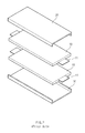
FIG. 1 is an exploded perspective view illustrating a tensile test jig according to a related art; -
FIG. 2 is an assembled perspective view illustrating the tensile test jig according to the related art; -
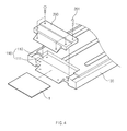
FIG. 3 is a perspective view illustrating a test jig according to a first embodiment of the present invention; -
FIG. 4 is a partial enlarged perspective view illustrating the test jig according to the first embodiment of the present invention; -
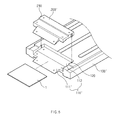
FIG. 5 is a perspective view illustrating a test jig according to a second embodiment of the present invention; -
FIG. 6 is a cross sectional view of theFIG. 5 ; and -
FIG. 7 is a perspective view illustrating a test jig according to a third embodiment of the present invention. - Exemplary embodiments of the present invention will now be described in detail with reference to the accompanying drawings.
- In a test jig according to the present invention, electrode leads are fixedly inserted into both ends of the test jig, which makes it possible to perform a tensile test on an ultrasonic-welded portion of the electrode lead without using an additional cell, thereby reducing costs and enhancing work efficiency.
- Hereinafter, with reference to the accompanying drawings, embodiments of the present invention will be described in detail enough for those of ordinary skilled in the art to easily perform embodiments of the invention. The invention may, however, be embodied in many different forms and should not be construed as being limited to the embodiments set forth herein. In the following description of the present invention, a detailed description of known functions and configurations incorporated herein will be omitted to avoid making the subject matter of the present invention unclear and, in every possible case, like reference numerals are used for referring to the same or similar elements in the description and drawings.
- According to a first embodiment of the present invention, as illustrated in
FIGS. 3 and4 , a test jig into which electrode leads are fixedly inserted includes a jigmain body 100 into which electrode leads 1 are inserted, and afixing member 200 fixing the electrode leads 1 inserted into the jigmain body 100. - The jig
main body 100 is shaped like a cell, and includesinsertion parts 110 into which the electrode leads 1 are inserted at both ends thereof, wherein theinsertion parts 110 includes insertion faces 111 outwardly extending from the both end portions of the jigmain body 100 and supporting the electrode leads 1, andcoupling faces 112 extending from the insertion faces 111 toward insides of the jigmain body 100 and brought into contact with thefixing member 200 which will be described later. - As the jig
main body 100 is manufactured in the shape of a cell to play a role of the cell, an additional cell is not needed. In other words, it is possible to perform a tensile test on the ultrasonic-welded portion in a state where the electrode leads 1 are inserted into theinsertion parts 110 of the jigmain body 100. - The jig
main body 100 herein may be manufactured in various shapes in accordance with the size and shape of a cell applied to a battery. - Meanwhile, the
insertion face 111 is inclined outwardly, and accordingly theelectrode lead 1 is slantly placed to increase work efficiency for the tensile test. - The
fixing member 200, which is provided for fixing theelectrode lead 1 inserted into theinsertion part 110, is brought into contact with theinsertion part 110 and fixed to the jigmain body 100 by using a plurality ofbolts 201 as a fixing means. - According to the first embodiment of the present invention, the
test jig 100 inserts theelectrode lead 1 into theinsertion face 111 of theinsertion part 110 provided in the jigmain body 100, and then brings thefixing member 200 into contact with theinsertion part 110. Next, thefixing member 200 is fixed to the jig main body by using the plurality ofblots 201 to complete assembly, and then the tensile test is performed on theelectrode lead 1 using the assembled test jig. - Therefore, the test jig according to the first embodiment of the present invention does not need to use the additional cell by virtue of the jig
main body 100 manufactured in the shape of the cell. - Hereinafter, for convenience of explanation, descriptions for the same or similar configurations or features as those described in the foregoing embodiment shall be skipped.
-
FIG. 5 is a perspective view illustrating a test jig according to a second embodiment of the present invention. - According to the second embodiment of the present invention, the test jig is configured such that a fixing member 200' is slidably coupled to an insertion part 110' by forming a guide protrusion and a guide groove on side portions of the insertion part 110' of the jig main body 100' and the fixing member 200', respectively.
- That is, as illustrated in
FIG. 5 , theguide protrusion 210 is provided on the side portion of the fixing member 200' and theguide groove 120 is provided in the sidewall of the insertion part 110' to which theguide protrusion 210 is slidably coupled. - Therefore, when the jig main body 100' and the fixing member 200' are coupled, the test jig according to the second embodiment of the present invention may efficiently adjust bolt coupling holes to thereby enhance work efficiency and reduce the mobility of the fixing member 200' to increase a fixing force.
- Meanwhile,
buffer parts 300 are further provided on corresponding portions of the insertion part 110' of the jig main body 100' and the fixing member 200' which face each other, as illustrated inFIG. 6 . Thebuffer part 300 is supported by a surface of theelectrode lead 1 to provide a pressing force more uniformly over an entire surface of theelectrode lead 1 when coupling the fixing member 200' to the jig main body 100' , thereby increasing a fixing force and also preventing theelectrode lead 1 from being damaged and from having a tensile force due to the pressing force. -
FIG. 7 is a perspective view illustrating a test jig according to a third embodiment of the present invention. - The test jig according to the third embodiment of the present invention, as illustrated in
FIG. 7 , includes alatch part 130 disposed at an interface between aninsertion face 111" and acoupling face 112" of aninsertion part 110" provided on a jigmain body 100". Thelatch part 130 may uniformly adjust the heights of the electrode leads 1 by allowing end portions of the electrode leads 1 inserted to the insertion faces 111" to be latched and thus equally adjust withdrawal lengths of the electrode leads 1 inserted to a plurality of test jigs. - A
latch groove 220 into which thelatch part 130 is inserted is provided in a bottom surface of thefixing member 200" and a coupling force is increased by inserting thelatch part 130 into thelatch groove 220 to bring thefixing member 200" into contact with theinsertion part 110. - An indicating
part 113 is provided at the center of theinsertion face 111" of theinsertion part 110" in a longitudinal direction of the jigmain body 100" and thus theelectrode lead 1 may be adjusted to be positioned at the center of theinsertion face 111", thereby equally adjusting left and right sides of the electrode leads 1 inserted into the plurality of test jigs. - According to the present invention, a tensile test is performed on an ultrasonic-welded portion of an electrode lead without use of an additional cell, thereby minimizing waste of unnecessary costs and enhancing work efficiency.
- While the present invention has been shown and described in connection with the exemplary embodiments, it will be apparent to those skilled in the art that modifications and variations can be made without departing from the spirit and scope of the invention as defined by the appended claims.
Claims (6)
- A test jig comprising:a jig main body having, at an end portion thereof, an insertion part into which an electrode lead is inserted; anda fixing member detachably coupled to the insertion part to fix the electrode lead inserted to the insertion part,wherein the insertion part comprises insertion faces outwardly extending from both end portions of the jig main body, and coupling faces extending from the insertion faces toward insides of the jig main body and brought into contact with the fixing member.
- The test jig of claim 1, wherein the insertion face is inclined outwardly.
- The test jig of claim 1, wherein a guide protrusion is provided on a side portion of the fixing member, and a guide groove is provided in a sidewall of the insertion part to allow the guide protrusion to be slidably coupled thereto.
- The test jig of claim 1, wherein pads having a buffering force are provided on corresponding portions of the insertion part and the fixing member which face each other.
- The test jig of claim 1, wherein an indicating part indicating a center of the insertion face is provided on the insertion face, so as to place the electrode lead at the center of the insertion face.
- The test jig of claim 1, wherein a latch part for latching a rear end of the electrode lead is provided on the insertion face, and the latch part is inserted into a latch groove provided in the bottom surface of the fixing member during coupling of the fixing member.
Applications Claiming Priority (2)
| Application Number | Priority Date | Filing Date | Title |
|---|---|---|---|
| KR1020130116299A KR101551534B1 (en) | 2013-09-30 | 2013-09-30 | Test jig |
| PCT/KR2014/005019 WO2015046710A1 (en) | 2013-09-30 | 2014-06-05 | Test jig |
Publications (3)
| Publication Number | Publication Date |
|---|---|
| EP2892105A1 true EP2892105A1 (en) | 2015-07-08 |
| EP2892105A4 EP2892105A4 (en) | 2015-08-26 |
| EP2892105B1 EP2892105B1 (en) | 2016-09-21 |
Family
ID=52743802
Family Applications (1)
| Application Number | Title | Priority Date | Filing Date |
|---|---|---|---|
| EP14783759.5A Active EP2892105B1 (en) | 2013-09-30 | 2014-06-05 | Test jig |
Country Status (6)
| Country | Link |
|---|---|
| US (1) | US9207153B2 (en) |
| EP (1) | EP2892105B1 (en) |
| JP (1) | JP6033969B2 (en) |
| KR (1) | KR101551534B1 (en) |
| CN (1) | CN104684688B (en) |
| WO (1) | WO2015046710A1 (en) |
Families Citing this family (9)
| Publication number | Priority date | Publication date | Assignee | Title |
|---|---|---|---|---|
| KR102132754B1 (en) * | 2017-06-29 | 2020-07-13 | 주식회사 엘지화학 | Jig apparatus for quality test of secondary battery |
| CN206969003U (en) * | 2017-07-10 | 2018-02-06 | 深圳市大疆创新科技有限公司 | test fixture for aircraft |
| CN110612634A (en) * | 2017-11-17 | 2019-12-24 | 株式会社Lg化学 | Pressurized jig for single cell for gas analysis and gas analysis device including the same |
| CN108458971A (en) * | 2018-01-08 | 2018-08-28 | 国电锅炉压力容器检验中心 | Position while welding lookup method |
| KR102543246B1 (en) | 2018-07-03 | 2023-06-14 | 주식회사 엘지에너지솔루션 | Sulfur-carbon complex, positive eletrode for lithium-sulfur battery and lithium-sulfur battery comprising the same |
| KR102952788B1 (en) | 2021-10-22 | 2026-04-15 | 주식회사 엘지에너지솔루션 | Jig for strength test of battery cell and apparatus for strength test of battery cell |
| KR20230105055A (en) | 2022-01-03 | 2023-07-11 | 주식회사 엘지에너지솔루션 | Cell tab tension measuring device and cell tab tension measuring mothod |
| KR20230120467A (en) | 2022-02-09 | 2023-08-17 | 주식회사 엘지에너지솔루션 | Dummy module for welding test |
| CN114660360B (en) * | 2022-03-23 | 2022-09-20 | 广东日信高精密科技有限公司 | Lithium battery electrode plate welding resistance testing device |
Family Cites Families (22)
| Publication number | Priority date | Publication date | Assignee | Title |
|---|---|---|---|---|
| JPS6064272U (en) * | 1983-10-07 | 1985-05-07 | 日本電気株式会社 | semiconductor test jig |
| DE4428310A1 (en) * | 1994-08-10 | 1996-02-15 | Manfred Schanz | Fastening device for a tool or workpiece |
| JPH11121307A (en) * | 1997-10-09 | 1999-04-30 | Taiyo Yuden Co Ltd | Device for forming external electrode of electronic parts |
| US6703707B1 (en) * | 1999-11-24 | 2004-03-09 | Denso Corporation | Semiconductor device having radiation structure |
| KR100343519B1 (en) * | 2000-04-28 | 2002-07-20 | 주식회사 엘리코파워 | Jig for testing a thin secondary battery |
| KR20010109588A (en) * | 2000-05-31 | 2001-12-12 | 신동희 | Jig for testing a secondary battery used for cellular phone |
| JP3171193B1 (en) * | 2000-06-12 | 2001-05-28 | 三菱マテリアル株式会社 | Edge insulating member of electrode plate, method of fixing and removing edge insulating member, and mounting jig for edge insulating member |
| JP2003331816A (en) * | 2002-05-08 | 2003-11-21 | Nissan Motor Co Ltd | Electrode connection structure for sheet-shaped secondary battery and secondary battery provided with the electrode connection structure |
| DE60307750T2 (en) * | 2002-05-08 | 2006-12-14 | Nissan Motor Co., Ltd., Yokohama | Secondary cell module and method for its production |
| US6946861B2 (en) * | 2004-01-08 | 2005-09-20 | Asustek Computer Inc. | Circuit board testing jig |
| JP2006196428A (en) * | 2004-05-31 | 2006-07-27 | Nissan Motor Co Ltd | Battery pack and manufacturing method thereof |
| US7489147B2 (en) * | 2004-07-15 | 2009-02-10 | Jsr Corporation | Inspection equipment of circuit board and inspection method of circuit board |
| KR101029019B1 (en) * | 2007-01-19 | 2011-04-14 | 주식회사 엘지화학 | Jig for charge / discharge of secondary batteries, apparatus for charge / discharge including the same, and performance test method for secondary batteries using the device for charge / discharge |
| WO2008090824A1 (en) * | 2007-01-25 | 2008-07-31 | Nec Corporation | Bag-like separator, electrode separator assembly, and method of producing electrode separator assembly |
| JP2010218766A (en) * | 2009-03-13 | 2010-09-30 | Sumitomo Electric Ind Ltd | Gripping method for lead conductor, manufacturing method for lead member, and fixing jig used for manufacture |
| JP2011100643A (en) * | 2009-11-06 | 2011-05-19 | Panasonic Corp | Manufacturing method of anode for lithium ion battery, and lithium ion battery |
| KR101418629B1 (en) * | 2010-09-29 | 2014-07-14 | 주식회사 엘지화학 | Jig for charging and discharging of secondarybattery |
| KR101359902B1 (en) * | 2011-01-31 | 2014-02-07 | 주식회사 엘지화학 | Jig for Charging and Discharging of Battery Cell |
| WO2013051099A1 (en) * | 2011-10-04 | 2013-04-11 | 富士通株式会社 | Testing jig and semiconductor device test method |
| JP5687172B2 (en) * | 2011-11-01 | 2015-03-18 | 三菱電機株式会社 | Semiconductor test jig and withstand voltage measurement method using the same |
| KR20130065465A (en) | 2011-12-09 | 2013-06-19 | (주)이티에이치 | Secondary battery charge and discharge gripper |
| KR101242096B1 (en) * | 2011-12-27 | 2013-03-11 | 주식회사 유엠테크 | Charging and discharging jig for battery |
-
2013
- 2013-09-30 KR KR1020130116299A patent/KR101551534B1/en active Active
-
2014
- 2014-06-05 JP JP2015539524A patent/JP6033969B2/en active Active
- 2014-06-05 CN CN201480001175.2A patent/CN104684688B/en active Active
- 2014-06-05 EP EP14783759.5A patent/EP2892105B1/en active Active
- 2014-06-05 WO PCT/KR2014/005019 patent/WO2015046710A1/en not_active Ceased
- 2014-10-21 US US14/519,857 patent/US9207153B2/en active Active
Also Published As
| Publication number | Publication date |
|---|---|
| CN104684688A (en) | 2015-06-03 |
| JP6033969B2 (en) | 2016-11-30 |
| JP2015531987A (en) | 2015-11-05 |
| CN104684688B (en) | 2016-08-31 |
| US20150090048A1 (en) | 2015-04-02 |
| EP2892105B1 (en) | 2016-09-21 |
| EP2892105A4 (en) | 2015-08-26 |
| WO2015046710A1 (en) | 2015-04-02 |
| KR20150037076A (en) | 2015-04-08 |
| KR101551534B1 (en) | 2015-09-08 |
| US9207153B2 (en) | 2015-12-08 |
Similar Documents
| Publication | Publication Date | Title |
|---|---|---|
| EP2892105B1 (en) | Test jig | |
| CN210723128U (en) | Battery module, battery pack including the same, and vehicle including the battery pack | |
| US8278877B2 (en) | Battery pack including a shock absorbing device | |
| KR101841801B1 (en) | Battery pack having bushing for coupling end plate | |
| CN100429807C (en) | Battery module | |
| KR101922304B1 (en) | Battery package with improved durability | |
| CN110114932B (en) | Battery modules and battery packs and vehicles including battery modules | |
| KR101864416B1 (en) | Battery formation gripper | |
| KR101858680B1 (en) | Apparatus and method for folding cells of secondary cell battery | |
| CN112005461A (en) | Apparatus for charging and discharging secondary battery | |
| KR20110004006A (en) | Jig for exclusive use of battery charge | |
| CN107848071A (en) | Wire bonding apparatus, battery module manufactured by the wire bonding apparatus, and battery pack including the battery module | |
| EP2958168A1 (en) | Battery module | |
| CN105706272B (en) | Battery module equipped with sensing module with improved coupling structure | |
| KR20150049985A (en) | Welding strength measuring device | |
| US12476332B2 (en) | Connection member connected to electrode leads by physical coupling and battery cell stack including the same | |
| KR20170028069A (en) | Battery module | |
| US20190123393A1 (en) | Battery pack | |
| KR101816708B1 (en) | Battery pack | |
| KR101032380B1 (en) | Electrode terminal of gripper for cell charging only | |
| CN109964352A (en) | Equipment for making battery packs | |
| KR101765749B1 (en) | Battery formation gripper with dual current grip terminal | |
| KR101829092B1 (en) | Battery Cell Seating Guide JIG And Method For Seating Battery Cell At End Plate | |
| CN218242307U (en) | Conductive terminal | |
| KR200467875Y1 (en) | Connection apparatus for battery tab |
Legal Events
| Date | Code | Title | Description |
|---|---|---|---|
| PUAI | Public reference made under article 153(3) epc to a published international application that has entered the european phase |
Free format text: ORIGINAL CODE: 0009012 |
|
| 17P | Request for examination filed |
Effective date: 20141020 |
|
| AK | Designated contracting states |
Kind code of ref document: A1 Designated state(s): AL AT BE BG CH CY CZ DE DK EE ES FI FR GB GR HR HU IE IS IT LI LT LU LV MC MK MT NL NO PL PT RO RS SE SI SK SM TR |
|
| AX | Request for extension of the european patent |
Extension state: BA ME |
|
| RA4 | Supplementary search report drawn up and despatched (corrected) |
Effective date: 20150729 |
|
| RIC1 | Information provided on ipc code assigned before grant |
Ipc: H01M 10/48 20060101AFI20150723BHEP Ipc: H01M 2/06 20060101ALI20150723BHEP |
|
| GRAP | Despatch of communication of intention to grant a patent |
Free format text: ORIGINAL CODE: EPIDOSNIGR1 |
|
| GRAS | Grant fee paid |
Free format text: ORIGINAL CODE: EPIDOSNIGR3 |
|
| DAX | Request for extension of the european patent (deleted) | ||
| INTG | Intention to grant announced |
Effective date: 20160711 |
|
| GRAA | (expected) grant |
Free format text: ORIGINAL CODE: 0009210 |
|
| AK | Designated contracting states |
Kind code of ref document: B1 Designated state(s): AL AT BE BG CH CY CZ DE DK EE ES FI FR GB GR HR HU IE IS IT LI LT LU LV MC MK MT NL NO PL PT RO RS SE SI SK SM TR |
|
| REG | Reference to a national code |
Ref country code: GB Ref legal event code: FG4D |
|
| REG | Reference to a national code |
Ref country code: CH Ref legal event code: EP |
|
| REG | Reference to a national code |
Ref country code: AT Ref legal event code: REF Ref document number: 831698 Country of ref document: AT Kind code of ref document: T Effective date: 20161015 |
|
| REG | Reference to a national code |
Ref country code: IE Ref legal event code: FG4D |
|
| REG | Reference to a national code |
Ref country code: DE Ref legal event code: R096 Ref document number: 602014003894 Country of ref document: DE |
|
| REG | Reference to a national code |
Ref country code: LT Ref legal event code: MG4D Ref country code: NL Ref legal event code: MP Effective date: 20160921 |
|
| PG25 | Lapsed in a contracting state [announced via postgrant information from national office to epo] |
Ref country code: FI Free format text: LAPSE BECAUSE OF FAILURE TO SUBMIT A TRANSLATION OF THE DESCRIPTION OR TO PAY THE FEE WITHIN THE PRESCRIBED TIME-LIMIT Effective date: 20160921 Ref country code: RS Free format text: LAPSE BECAUSE OF FAILURE TO SUBMIT A TRANSLATION OF THE DESCRIPTION OR TO PAY THE FEE WITHIN THE PRESCRIBED TIME-LIMIT Effective date: 20160921 Ref country code: LT Free format text: LAPSE BECAUSE OF FAILURE TO SUBMIT A TRANSLATION OF THE DESCRIPTION OR TO PAY THE FEE WITHIN THE PRESCRIBED TIME-LIMIT Effective date: 20160921 Ref country code: NO Free format text: LAPSE BECAUSE OF FAILURE TO SUBMIT A TRANSLATION OF THE DESCRIPTION OR TO PAY THE FEE WITHIN THE PRESCRIBED TIME-LIMIT Effective date: 20161221 |
|
| REG | Reference to a national code |
Ref country code: AT Ref legal event code: MK05 Ref document number: 831698 Country of ref document: AT Kind code of ref document: T Effective date: 20160921 |
|
| PG25 | Lapsed in a contracting state [announced via postgrant information from national office to epo] |
Ref country code: SE Free format text: LAPSE BECAUSE OF FAILURE TO SUBMIT A TRANSLATION OF THE DESCRIPTION OR TO PAY THE FEE WITHIN THE PRESCRIBED TIME-LIMIT Effective date: 20160921 Ref country code: GR Free format text: LAPSE BECAUSE OF FAILURE TO SUBMIT A TRANSLATION OF THE DESCRIPTION OR TO PAY THE FEE WITHIN THE PRESCRIBED TIME-LIMIT Effective date: 20161222 Ref country code: NL Free format text: LAPSE BECAUSE OF FAILURE TO SUBMIT A TRANSLATION OF THE DESCRIPTION OR TO PAY THE FEE WITHIN THE PRESCRIBED TIME-LIMIT Effective date: 20160921 Ref country code: LV Free format text: LAPSE BECAUSE OF FAILURE TO SUBMIT A TRANSLATION OF THE DESCRIPTION OR TO PAY THE FEE WITHIN THE PRESCRIBED TIME-LIMIT Effective date: 20160921 |
|
| PG25 | Lapsed in a contracting state [announced via postgrant information from national office to epo] |
Ref country code: EE Free format text: LAPSE BECAUSE OF FAILURE TO SUBMIT A TRANSLATION OF THE DESCRIPTION OR TO PAY THE FEE WITHIN THE PRESCRIBED TIME-LIMIT Effective date: 20160921 Ref country code: RO Free format text: LAPSE BECAUSE OF FAILURE TO SUBMIT A TRANSLATION OF THE DESCRIPTION OR TO PAY THE FEE WITHIN THE PRESCRIBED TIME-LIMIT Effective date: 20160921 |
|
| REG | Reference to a national code |
Ref country code: FR Ref legal event code: PLFP Year of fee payment: 4 |
|
| PG25 | Lapsed in a contracting state [announced via postgrant information from national office to epo] |
Ref country code: SK Free format text: LAPSE BECAUSE OF FAILURE TO SUBMIT A TRANSLATION OF THE DESCRIPTION OR TO PAY THE FEE WITHIN THE PRESCRIBED TIME-LIMIT Effective date: 20160921 Ref country code: PL Free format text: LAPSE BECAUSE OF FAILURE TO SUBMIT A TRANSLATION OF THE DESCRIPTION OR TO PAY THE FEE WITHIN THE PRESCRIBED TIME-LIMIT Effective date: 20160921 Ref country code: BE Free format text: LAPSE BECAUSE OF FAILURE TO SUBMIT A TRANSLATION OF THE DESCRIPTION OR TO PAY THE FEE WITHIN THE PRESCRIBED TIME-LIMIT Effective date: 20160921 Ref country code: ES Free format text: LAPSE BECAUSE OF FAILURE TO SUBMIT A TRANSLATION OF THE DESCRIPTION OR TO PAY THE FEE WITHIN THE PRESCRIBED TIME-LIMIT Effective date: 20160921 Ref country code: AT Free format text: LAPSE BECAUSE OF FAILURE TO SUBMIT A TRANSLATION OF THE DESCRIPTION OR TO PAY THE FEE WITHIN THE PRESCRIBED TIME-LIMIT Effective date: 20160921 Ref country code: SM Free format text: LAPSE BECAUSE OF FAILURE TO SUBMIT A TRANSLATION OF THE DESCRIPTION OR TO PAY THE FEE WITHIN THE PRESCRIBED TIME-LIMIT Effective date: 20160921 Ref country code: CZ Free format text: LAPSE BECAUSE OF FAILURE TO SUBMIT A TRANSLATION OF THE DESCRIPTION OR TO PAY THE FEE WITHIN THE PRESCRIBED TIME-LIMIT Effective date: 20160921 Ref country code: IS Free format text: LAPSE BECAUSE OF FAILURE TO SUBMIT A TRANSLATION OF THE DESCRIPTION OR TO PAY THE FEE WITHIN THE PRESCRIBED TIME-LIMIT Effective date: 20170121 Ref country code: PT Free format text: LAPSE BECAUSE OF FAILURE TO SUBMIT A TRANSLATION OF THE DESCRIPTION OR TO PAY THE FEE WITHIN THE PRESCRIBED TIME-LIMIT Effective date: 20170123 Ref country code: BG Free format text: LAPSE BECAUSE OF FAILURE TO SUBMIT A TRANSLATION OF THE DESCRIPTION OR TO PAY THE FEE WITHIN THE PRESCRIBED TIME-LIMIT Effective date: 20161221 |
|
| REG | Reference to a national code |
Ref country code: DE Ref legal event code: R097 Ref document number: 602014003894 Country of ref document: DE |
|
| PG25 | Lapsed in a contracting state [announced via postgrant information from national office to epo] |
Ref country code: IT Free format text: LAPSE BECAUSE OF FAILURE TO SUBMIT A TRANSLATION OF THE DESCRIPTION OR TO PAY THE FEE WITHIN THE PRESCRIBED TIME-LIMIT Effective date: 20160921 |
|
| PLBE | No opposition filed within time limit |
Free format text: ORIGINAL CODE: 0009261 |
|
| STAA | Information on the status of an ep patent application or granted ep patent |
Free format text: STATUS: NO OPPOSITION FILED WITHIN TIME LIMIT |
|
| PG25 | Lapsed in a contracting state [announced via postgrant information from national office to epo] |
Ref country code: DK Free format text: LAPSE BECAUSE OF FAILURE TO SUBMIT A TRANSLATION OF THE DESCRIPTION OR TO PAY THE FEE WITHIN THE PRESCRIBED TIME-LIMIT Effective date: 20160921 |
|
| 26N | No opposition filed |
Effective date: 20170622 |
|
| PG25 | Lapsed in a contracting state [announced via postgrant information from national office to epo] |
Ref country code: SI Free format text: LAPSE BECAUSE OF FAILURE TO SUBMIT A TRANSLATION OF THE DESCRIPTION OR TO PAY THE FEE WITHIN THE PRESCRIBED TIME-LIMIT Effective date: 20160921 |
|
| REG | Reference to a national code |
Ref country code: DE Ref legal event code: R119 Ref document number: 602014003894 Country of ref document: DE |
|
| PG25 | Lapsed in a contracting state [announced via postgrant information from national office to epo] |
Ref country code: MC Free format text: LAPSE BECAUSE OF FAILURE TO SUBMIT A TRANSLATION OF THE DESCRIPTION OR TO PAY THE FEE WITHIN THE PRESCRIBED TIME-LIMIT Effective date: 20160921 |
|
| REG | Reference to a national code |
Ref country code: CH Ref legal event code: PL |
|
| REG | Reference to a national code |
Ref country code: IE Ref legal event code: MM4A |
|
| PG25 | Lapsed in a contracting state [announced via postgrant information from national office to epo] |
Ref country code: LI Free format text: LAPSE BECAUSE OF NON-PAYMENT OF DUE FEES Effective date: 20170630 Ref country code: IE Free format text: LAPSE BECAUSE OF NON-PAYMENT OF DUE FEES Effective date: 20170605 Ref country code: DE Free format text: LAPSE BECAUSE OF NON-PAYMENT OF DUE FEES Effective date: 20180103 Ref country code: CH Free format text: LAPSE BECAUSE OF NON-PAYMENT OF DUE FEES Effective date: 20170630 Ref country code: LU Free format text: LAPSE BECAUSE OF NON-PAYMENT OF DUE FEES Effective date: 20170605 |
|
| REG | Reference to a national code |
Ref country code: FR Ref legal event code: PLFP Year of fee payment: 5 |
|
| PG25 | Lapsed in a contracting state [announced via postgrant information from national office to epo] |
Ref country code: MT Free format text: LAPSE BECAUSE OF NON-PAYMENT OF DUE FEES Effective date: 20170605 |
|
| PG25 | Lapsed in a contracting state [announced via postgrant information from national office to epo] |
Ref country code: AL Free format text: LAPSE BECAUSE OF FAILURE TO SUBMIT A TRANSLATION OF THE DESCRIPTION OR TO PAY THE FEE WITHIN THE PRESCRIBED TIME-LIMIT Effective date: 20160921 |
|
| GBPC | Gb: european patent ceased through non-payment of renewal fee |
Effective date: 20180605 |
|
| PG25 | Lapsed in a contracting state [announced via postgrant information from national office to epo] |
Ref country code: GB Free format text: LAPSE BECAUSE OF NON-PAYMENT OF DUE FEES Effective date: 20180605 |
|
| PG25 | Lapsed in a contracting state [announced via postgrant information from national office to epo] |
Ref country code: HU Free format text: LAPSE BECAUSE OF FAILURE TO SUBMIT A TRANSLATION OF THE DESCRIPTION OR TO PAY THE FEE WITHIN THE PRESCRIBED TIME-LIMIT; INVALID AB INITIO Effective date: 20140605 |
|
| PG25 | Lapsed in a contracting state [announced via postgrant information from national office to epo] |
Ref country code: CY Free format text: LAPSE BECAUSE OF FAILURE TO SUBMIT A TRANSLATION OF THE DESCRIPTION OR TO PAY THE FEE WITHIN THE PRESCRIBED TIME-LIMIT Effective date: 20160921 |
|
| PG25 | Lapsed in a contracting state [announced via postgrant information from national office to epo] |
Ref country code: MK Free format text: LAPSE BECAUSE OF FAILURE TO SUBMIT A TRANSLATION OF THE DESCRIPTION OR TO PAY THE FEE WITHIN THE PRESCRIBED TIME-LIMIT Effective date: 20160921 |
|
| PG25 | Lapsed in a contracting state [announced via postgrant information from national office to epo] |
Ref country code: TR Free format text: LAPSE BECAUSE OF FAILURE TO SUBMIT A TRANSLATION OF THE DESCRIPTION OR TO PAY THE FEE WITHIN THE PRESCRIBED TIME-LIMIT Effective date: 20160921 |
|
| PG25 | Lapsed in a contracting state [announced via postgrant information from national office to epo] |
Ref country code: HR Free format text: LAPSE BECAUSE OF FAILURE TO SUBMIT A TRANSLATION OF THE DESCRIPTION OR TO PAY THE FEE WITHIN THE PRESCRIBED TIME-LIMIT Effective date: 20160921 |
|
| P01 | Opt-out of the competence of the unified patent court (upc) registered |
Effective date: 20230512 |
|
| PGFP | Annual fee paid to national office [announced via postgrant information from national office to epo] |
Ref country code: FR Payment date: 20250521 Year of fee payment: 12 |