EP2891920A1 - Lichtverstärkende Komponente und fotografische Vorrichtung damit - Google Patents
Lichtverstärkende Komponente und fotografische Vorrichtung damit Download PDFInfo
- Publication number
- EP2891920A1 EP2891920A1 EP14200417.5A EP14200417A EP2891920A1 EP 2891920 A1 EP2891920 A1 EP 2891920A1 EP 14200417 A EP14200417 A EP 14200417A EP 2891920 A1 EP2891920 A1 EP 2891920A1
- Authority
- EP
- European Patent Office
- Prior art keywords
- reflecting surface
- light
- enhancing component
- component
- light source
- Prior art date
- Legal status (The legal status is an assumption and is not a legal conclusion. Google has not performed a legal analysis and makes no representation as to the accuracy of the status listed.)
- Granted
Links
- 238000010586 diagram Methods 0.000 description 6
- 230000000694 effects Effects 0.000 description 4
- 230000003247 decreasing effect Effects 0.000 description 3
- 241000251468 Actinopterygii Species 0.000 description 2
- 238000005286 illumination Methods 0.000 description 2
- 230000002093 peripheral effect Effects 0.000 description 2
- 230000006399 behavior Effects 0.000 description 1
- 230000002708 enhancing effect Effects 0.000 description 1
- 230000002349 favourable effect Effects 0.000 description 1
- 238000012986 modification Methods 0.000 description 1
- 230000004048 modification Effects 0.000 description 1
- 238000012544 monitoring process Methods 0.000 description 1
Images
Classifications
-
- F—MECHANICAL ENGINEERING; LIGHTING; HEATING; WEAPONS; BLASTING
- F21—LIGHTING
- F21V—FUNCTIONAL FEATURES OR DETAILS OF LIGHTING DEVICES OR SYSTEMS THEREOF; STRUCTURAL COMBINATIONS OF LIGHTING DEVICES WITH OTHER ARTICLES, NOT OTHERWISE PROVIDED FOR
- F21V7/00—Reflectors for light sources
- F21V7/0025—Combination of two or more reflectors for a single light source
-
- F—MECHANICAL ENGINEERING; LIGHTING; HEATING; WEAPONS; BLASTING
- F21—LIGHTING
- F21V—FUNCTIONAL FEATURES OR DETAILS OF LIGHTING DEVICES OR SYSTEMS THEREOF; STRUCTURAL COMBINATIONS OF LIGHTING DEVICES WITH OTHER ARTICLES, NOT OTHERWISE PROVIDED FOR
- F21V33/00—Structural combinations of lighting devices with other articles, not otherwise provided for
- F21V33/0064—Health, life-saving or fire-fighting equipment
- F21V33/0076—Safety or security signalisation, e.g. smoke or burglar alarms, earthquake detectors; Self-defence devices
-
- G—PHYSICS
- G03—PHOTOGRAPHY; CINEMATOGRAPHY; ANALOGOUS TECHNIQUES USING WAVES OTHER THAN OPTICAL WAVES; ELECTROGRAPHY; HOLOGRAPHY
- G03B—APPARATUS OR ARRANGEMENTS FOR TAKING PHOTOGRAPHS OR FOR PROJECTING OR VIEWING THEM; APPARATUS OR ARRANGEMENTS EMPLOYING ANALOGOUS TECHNIQUES USING WAVES OTHER THAN OPTICAL WAVES; ACCESSORIES THEREFOR
- G03B15/00—Special procedures for taking photographs; Apparatus therefor
- G03B15/02—Illuminating scene
- G03B15/03—Combinations of cameras with lighting apparatus; Flash units
- G03B15/035—Combinations of cameras with incandescent lamps
-
- G—PHYSICS
- G08—SIGNALLING
- G08B—SIGNALLING OR CALLING SYSTEMS; ORDER TELEGRAPHS; ALARM SYSTEMS
- G08B13/00—Burglar, theft or intruder alarms
- G08B13/18—Actuation by interference with heat, light, or radiation of shorter wavelength; Actuation by intruding sources of heat, light, or radiation of shorter wavelength
- G08B13/189—Actuation by interference with heat, light, or radiation of shorter wavelength; Actuation by intruding sources of heat, light, or radiation of shorter wavelength using passive radiation detection systems
- G08B13/194—Actuation by interference with heat, light, or radiation of shorter wavelength; Actuation by intruding sources of heat, light, or radiation of shorter wavelength using passive radiation detection systems using image scanning and comparing systems
- G08B13/196—Actuation by interference with heat, light, or radiation of shorter wavelength; Actuation by intruding sources of heat, light, or radiation of shorter wavelength using passive radiation detection systems using image scanning and comparing systems using television cameras
- G08B13/19617—Surveillance camera constructional details
- G08B13/19626—Surveillance camera constructional details optical details, e.g. lenses, mirrors or multiple lenses
-
- H—ELECTRICITY
- H04—ELECTRIC COMMUNICATION TECHNIQUE
- H04N—PICTORIAL COMMUNICATION, e.g. TELEVISION
- H04N23/00—Cameras or camera modules comprising electronic image sensors; Control thereof
- H04N23/50—Constructional details
- H04N23/51—Housings
-
- H—ELECTRICITY
- H04—ELECTRIC COMMUNICATION TECHNIQUE
- H04N—PICTORIAL COMMUNICATION, e.g. TELEVISION
- H04N23/00—Cameras or camera modules comprising electronic image sensors; Control thereof
- H04N23/56—Cameras or camera modules comprising electronic image sensors; Control thereof provided with illuminating means
-
- H—ELECTRICITY
- H04—ELECTRIC COMMUNICATION TECHNIQUE
- H04N—PICTORIAL COMMUNICATION, e.g. TELEVISION
- H04N23/00—Cameras or camera modules comprising electronic image sensors; Control thereof
- H04N23/70—Circuitry for compensating brightness variation in the scene
- H04N23/75—Circuitry for compensating brightness variation in the scene by influencing optical camera components
-
- H—ELECTRICITY
- H04—ELECTRIC COMMUNICATION TECHNIQUE
- H04N—PICTORIAL COMMUNICATION, e.g. TELEVISION
- H04N7/00—Television systems
- H04N7/18—Closed-circuit television [CCTV] systems, i.e. systems in which the video signal is not broadcast
-
- H—ELECTRICITY
- H04—ELECTRIC COMMUNICATION TECHNIQUE
- H04N—PICTORIAL COMMUNICATION, e.g. TELEVISION
- H04N7/00—Television systems
- H04N7/18—Closed-circuit television [CCTV] systems, i.e. systems in which the video signal is not broadcast
- H04N7/183—Closed-circuit television [CCTV] systems, i.e. systems in which the video signal is not broadcast for receiving images from a single remote source
-
- F—MECHANICAL ENGINEERING; LIGHTING; HEATING; WEAPONS; BLASTING
- F21—LIGHTING
- F21V—FUNCTIONAL FEATURES OR DETAILS OF LIGHTING DEVICES OR SYSTEMS THEREOF; STRUCTURAL COMBINATIONS OF LIGHTING DEVICES WITH OTHER ARTICLES, NOT OTHERWISE PROVIDED FOR
- F21V7/00—Reflectors for light sources
- F21V7/0083—Array of reflectors for a cluster of light sources, e.g. arrangement of multiple light sources in one plane
-
- F—MECHANICAL ENGINEERING; LIGHTING; HEATING; WEAPONS; BLASTING
- F21—LIGHTING
- F21V—FUNCTIONAL FEATURES OR DETAILS OF LIGHTING DEVICES OR SYSTEMS THEREOF; STRUCTURAL COMBINATIONS OF LIGHTING DEVICES WITH OTHER ARTICLES, NOT OTHERWISE PROVIDED FOR
- F21V7/00—Reflectors for light sources
- F21V7/04—Optical design
- F21V7/05—Optical design plane
-
- F—MECHANICAL ENGINEERING; LIGHTING; HEATING; WEAPONS; BLASTING
- F21—LIGHTING
- F21V—FUNCTIONAL FEATURES OR DETAILS OF LIGHTING DEVICES OR SYSTEMS THEREOF; STRUCTURAL COMBINATIONS OF LIGHTING DEVICES WITH OTHER ARTICLES, NOT OTHERWISE PROVIDED FOR
- F21V7/00—Reflectors for light sources
- F21V7/04—Optical design
- F21V7/09—Optical design with a combination of different curvatures
-
- G—PHYSICS
- G03—PHOTOGRAPHY; CINEMATOGRAPHY; ANALOGOUS TECHNIQUES USING WAVES OTHER THAN OPTICAL WAVES; ELECTROGRAPHY; HOLOGRAPHY
- G03B—APPARATUS OR ARRANGEMENTS FOR TAKING PHOTOGRAPHS OR FOR PROJECTING OR VIEWING THEM; APPARATUS OR ARRANGEMENTS EMPLOYING ANALOGOUS TECHNIQUES USING WAVES OTHER THAN OPTICAL WAVES; ACCESSORIES THEREFOR
- G03B2215/00—Special procedures for taking photographs; Apparatus therefor
- G03B2215/05—Combinations of cameras with electronic flash units
- G03B2215/0582—Reflectors
Definitions
- the disclosure relates to a light-enhancing component. More particularly, the disclosure relates to a light-enhancing component with asymmetrical reflective surfaces, and a photographic device having the same.
- Surveillance cameras are widely used in different kinds of locations, such as industry plants, dormitories, stores, apartments, entrances of buildings or communities, hallways and other remote locations.
- the surveillance camera is for monitoring and recording human behaviors or accidents so that it is favorable for maintaining social control, recognizing threats, and avoiding criminal activities.
- a surveillance camera generally comprises a light-enhancing component for illuminating the places with limited or no lighting.
- the light-enhancing component is manufactured with a poor design, it is unable to illuminate the whole area that is trying to be captured and recorded and the surveillance camera cannot capture images clearly.
- a fish-eye camera has been developed for decreasing the blind spots of surveillance cameras. The viewing range of the fish-eye camera is wide, and the fish-eye camera usually comprises an infrared light source.
- the fish-eye camera needs to be equipped with a lighting device to light up the whole area evenly, since the emission angle or the light intensity of the infrared light source is limited.
- a viewing angle of the fish-eye camera is greater than 170 degrees, but a projection angle of the infrared light source is between about 90 degrees and 100 degrees.
- the projection angle of the infrared light source cannot cover the viewing angle of the fish-eye camera, limiting the image quality of the fish-eye camera.
- the center of the images has sufficient illumination, but the peripheral of the images is darker. In other words, the images are captured unevenly, which is called as the "flashlight effect". To sum up, it is important to improve the image quality of surveillance cameras.
- the disclosure provides a light-enhancing component and a photographic device having the same, to improve the image quality of surveillance cameras.
- a light-enhancing component which comprises a light reflective unit and a light source.
- the light reflective unit comprises a first reflecting surface and a second reflecting surface.
- the light source is disposed between the first reflecting surface and the second reflecting surface. An inclination of the first reflecting surface is different from an inclination of the second reflecting surface.
- a photographic device which comprises the at least one light-enhancing component and an image capturing component.
- the image capturing component is for capturing an image.
- the at least one light-enhancing component is disposed at a side of the image capturing component. When the image capturing component captures the image, the at least one light-enhancing component is for emitting light.
- the light-enhancing component and the photographic device having the same of the disclosure due to the asymmetry design between the first reflecting surface and the second reflecting surface, lights emitted from the light source can be uniformly reflected within a photographic range (x-z plane and y-z plane) of the image capturing component. Accordingly, the image quality of the surveillance camera can be improved when the surveillance camera is used in an environment with insufficient lighting.
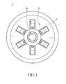
- FIG. 1 is a schematic plan view of a photographic device according to a first embodiment of the disclosure.
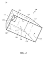
- FIG. 2 is a perspective view of a light-enhancing component in FIG. 1 .
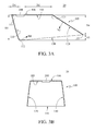
- FIG. 3A and FIG. 3B are cross-sectional views of FIG. 2 .
- the photographic device 5 comprises a shell 6, an image capturing component 10 and at least one light-enhancing component 20.
- the image capturing component 10 is a fish eye lens. A major portion of the image capturing component 10 is located inside the shell 6, whereas another part of the image capturing component 10 protrudes outward from the shell 6 for capturing an image.
- the quantity of the at least one light-enhancing component 20 is six.
- the quantity of the at least one light-enhancing component 20 is not limited to six.
- the quantity of the at least one light-enhancing component 20 is one in other embodiments, and the light-enhancing component 20 is located at a side of the image capturing component 10.
- the light-enhancing component 20 comprises a light reflective unit 100 and a light source 200.
- the light reflective unit 100 comprises a reflective bottom surface 105, a first reflecting surface 110, a second reflecting surface 120, a third reflecting surface 130 and a fourth reflecting surface 140.
- the first reflecting surface 110 is opposite to the second reflecting surface 120
- the third reflecting surface 130 is opposite to the fourth reflecting surface 140.
- the first reflecting surface 110, the second reflecting surface 120, the third reflecting surface 130 and the fourth reflecting surface 140 are connected to the peripheral of the same side of the reflective bottom surface 105 and both of them extend outward, respectively.
- an opening 150 is formed by the first reflecting surface 110, the second reflecting surface 120, the third reflecting surface 130 and the fourth reflecting surface 140 away from the reflective bottom surface 105.
- the first reflecting surface 110 is located between the image capturing component 10 and the light source 200.
- the first reflecting surface 110 and the second reflecting surface 120 are asymmetric, and the third reflecting surface 130 and the fourth reflecting surface 140 are symmetric.
- the asymmetry between the first reflecting surface 110 and the second reflecting surface 120 will be described as follows.
- a height of the first reflecting surface 110 is greater than a height of the second reflecting surface 120 (extended from the reflective bottom surface 105).
- the first reflecting surface 110 has a first end 111 and a second end 112 which are opposite to each other
- the second reflecting surface 120 has a first end 121 and a second end 122 which are opposite to each other.
- the first end 111 of the first reflecting surface 110 and the first end 121 of the second reflecting surface 120 are connected to two sides of the reflective bottom surface 105 which are opposite to each other.
- a vertical distance D3 between the reflective bottom surface 105 and the second end 112 of the first reflecting surface 110 is greater than a vertical distance D4 between the reflective bottom surface 105 and the second end 122 of the second reflecting surface 120 (the relative height of the second reflecting surface 120 which is parallel to the normal line of the reflective bottom surface 105).
- a horizontal distance between the first end 111 and the second end 112 of the first reflecting surface 110 is greater than a horizontal distance D1 between the light source 200 and the first end 111 of the first reflecting surface 110.
- an inclination of the first reflecting surface 110 and an inclination of the second reflecting surface 120 are also asymmetric.
- the first reflecting surface 110 and the second reflecting surface 120 are tilted toward the same direction with respect to the reflective bottom surface 105, and the inclination of the first reflecting surface 110 is different from the inclination of the second reflecting surface 120.
- a direction indicated by a normal vector N2 of the second reflecting surface 120 is far away from the reflective bottom surface 105, certain light emitted from the light source 200 is reflected by the second reflecting surface 120 towards the region under the reflective bottom surface 105 accordingly.
- a direction indicated by a normal vector N1 of the first reflecting surface 110 is toward the reflective bottom surface 105.
- the inclination of the second reflecting surface 120 relative to the reflective bottom surface 105 is greater than the inclination of the first reflecting surface 110 relative to the reflective bottom surface 105.
- the first type is the light reflected by the first reflecting surface 110, the reflective bottom surface 105 and the second reflecting surface 120 sequentially, and finally located under the reflective bottom surface 105.
- the second type is the light reflected by the first reflecting surface 110 and the second reflecting surface 120 sequentially, and finally located under the reflective bottom surface 105.
- the third type is the light reflected outward between an interval (formed by a height difference D5 between the first reflecting surface 110 and the second reflecting surface 120) by the first reflecting surface 110 (towards the right side of second reflecting surface 120 in FIG. 3A ).
- the first reflecting surface 110 is a curved surface
- the second reflecting surface 120 is a plane
- the first reflecting surface 110 and the second reflecting surface 120 are asymmetric with respect to the reflective bottom surface 105.
- both the first reflecting surface 110 and the second reflecting surface 120 are curved surfaces
- a curvature of the first reflecting surface 110 is different from a curvature of the second reflecting surface 120
- the first reflecting surface 110 and the second reflecting surface 120 are asymmetric with respect to the reflective bottom surface 105.
- the symmetry between the third reflecting surface 130 and the fourth reflecting surface 140 will be described as follows.
- a height of the third reflecting surface 130 and a height of the fourth reflecting surface 140 are symmetric.
- the height of the third reflecting surface 130 and the height of the fourth reflecting surface 140 are gradually decreased from the second end 112 of the first reflecting surface 110 to the second end 122 of the second reflecting surface 120 (namely, the height of the third reflecting surface 130 and the height of the fourth reflecting surface 140 are gradually decreased from D3 to D4).
- An inclination of the third reflecting surface 130 and an inclination of the fourth reflecting surface 140 are symmetric, and a curvature of the third reflecting surface 130 and a curvature of the fourth reflecting surface 140 are also symmetric.
- the inclination of the third reflecting surface 130 and the inclination of the fourth reflecting surface 140 are the same, and the curvature of the third reflecting surface 130 and the curvature of the fourth reflecting surface 140 are also the same.
- the reflective bottom surface 105 further has a notch 106.
- the light source 200 passes through the notch 106 and is enclosed by the first reflecting surface 110, the second reflecting surface 120, the third reflecting surface 130 and the fourth reflecting surface 140.
- An interval D1 between the light source 200 and the first reflecting surface 110 is less than an interval D2 between the light source 200 and the second reflecting surface 120.
- An interval between the light source 200 and the third reflecting surface 130 is equal to an interval between the light source 200 and the fourth reflecting surface 140.
- the light emitted from the light source 200 is reflected outward from the opening 150 by the first reflecting surface 110, the second reflecting surface 120, the third reflecting surface 130 and the fourth reflecting surface 140, thereby enhancing the illumination of the image capturing component 10.
- the light-enhancing components 20 are arranged around the image capturing component 10 with constant angles, namely, evenly distributed around the image capturing component 10.
- constant angles are 60 degrees, and all compensating angles are interconnected with each other to form a 360-degree compensating angle.
- the compensating angle of a single light-enhancing component 20 is greater than 60 degrees, the light-enhancing components 20 are not being arranged around the image capturing component 10 with constant angles. In other words, a user can adjust the quantity and the arrangement of the light-enhancing component 20 randomly, to form the 360-degree compensating angle.
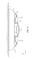
- FIG. 4 is a side view of the photographic device in FIG. 1 when the photographic device is disposed on a ceiling.
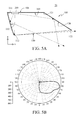
- FIG. 5A is a schematic view of a first reflecting surface and a second reflecting surface of a light reflective unit in FIG. 2 where light emitted from a light source is reflected.
- FIG. 5B is an intensity distribution diagram of the lights reflected by the first reflecting surface and the second reflecting surface according to FIG. 5A .
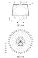
- FIG. 6A is a schematic view of a third reflecting surface and a fourth reflecting surface of the light reflective unit in FIG. 2 where lights emitted from the light source is reflected.
- FIG. 6B is an intensity distribution diagram of the lights reflected by the third reflecting surface and the fourth reflecting surface according to FIG. 6A .
- the photographic device 5 is disposed on the ceiling 4. Since the image capturing component 10 is the fish eye lens, the image capturing component 10 can capture the images of the ceiling 4 or under the ceiling 4. In the following description, for purposes of clarity and conciseness of the description, a three dimensional coordinate is established and the image capturing component 10 is taken as an origin point of the three dimensional coordinate.
- a plane parallel to the ceiling 4 is an x-y plane. Planes perpendicular to the ceiling 4 are an x-z plane and a y-z plane, respectively.
- the light-enhancing effect of the light-enhancing component 20 at the x-z plane and the y-z plane is described.
- FIG. 4 and FIG. 5A due to the asymmetry between the first reflecting surface 110 and the second reflecting surface 120, parts of the lights are reflected by the first reflecting surface 110 toward the ceiling 4 which is away from the image capturing component 10 (the third type of the lights as above-mentioned) for illuminating the ceiling 4, and the other light is reflected by the second reflecting surface 120 toward the region which is under the ceiling 4 (the first type and the second type of the lights as above-mentioned), for illuminating the region under the ceiling 4.
- an intensity distribution diagram of the light-enhancing component 20 is formed asymmetrically at the x-z plane and the y-z plane (as shown in FIG. 5B ). Therefore, the image capturing component 10 can capture the images clearly, and the image quality of the photographic device 5 is improved.
- the light-enhancing effect of the light-enhancing component 20 on the x-y plane is described.
- an intensity distribution diagram of the light-enhancing component 20 is formed symmetrically at the x-y plane (as shown in FIG. 6B ).
- the compensating angle of a single light-enhancing component 20 is slightly larger than 60 degrees (as a solid line shown in FIG. 6B ).
- a single light-enhancing component 20 can illuminate the region near the image capturing component 10 in a range of 0 to 60 degrees.
- all compensating angles of the light-enhancing components 20 are interconnected with each other to form the 360-degree compensating angle (the lights can be omni-directional) as the solid line and dotted lines shown in FIG. 6B , thereby illuminating (lighting up) the region (at the x-y plane) around the image capturing component 10.
- the lights emitted from the light source can be uniformly reflected within a photographic range (the x-z plane and the y-z plane) of the image capturing component. Accordingly, the image quality of the surveillance camera can be improved when the surveillance camera is used in an environment without sufficient lighting.
- the 360-degree compensating angle is formed (the lights can be omni-directional), thereby illuminating (lighting up) the region (at the x-y plane) around the image capturing component.
Landscapes
- Engineering & Computer Science (AREA)
- Physics & Mathematics (AREA)
- General Physics & Mathematics (AREA)
- Multimedia (AREA)
- Signal Processing (AREA)
- General Engineering & Computer Science (AREA)
- Computer Security & Cryptography (AREA)
- Environmental & Geological Engineering (AREA)
- Studio Devices (AREA)
- Lenses (AREA)
- Stroboscope Apparatuses (AREA)
- Optical Elements Other Than Lenses (AREA)
Applications Claiming Priority (1)
| Application Number | Priority Date | Filing Date | Title |
|---|---|---|---|
| TW103100257A TWI491970B (zh) | 2014-01-03 | 2014-01-03 | 補光結構及應用其補光結構的攝影裝置 |
Publications (2)
| Publication Number | Publication Date |
|---|---|
| EP2891920A1 true EP2891920A1 (de) | 2015-07-08 |
| EP2891920B1 EP2891920B1 (de) | 2016-10-12 |
Family
ID=52272938
Family Applications (1)
| Application Number | Title | Priority Date | Filing Date |
|---|---|---|---|
| EP14200417.5A Active EP2891920B1 (de) | 2014-01-03 | 2014-12-29 | Lichtverstärkende Komponente und fotografische Vorrichtung damit |
Country Status (4)
| Country | Link |
|---|---|
| US (1) | US9534763B2 (de) |
| EP (1) | EP2891920B1 (de) |
| CN (1) | CN104765225B (de) |
| TW (1) | TWI491970B (de) |
Families Citing this family (6)
| Publication number | Priority date | Publication date | Assignee | Title |
|---|---|---|---|---|
| TWI625589B (zh) * | 2017-03-27 | 2018-06-01 | 晶睿通訊股份有限公司 | 燈杯及攝影機 |
| CN108366179A (zh) * | 2018-01-18 | 2018-08-03 | 深圳市新良田科技股份有限公司 | 能充分且相对均匀补光的高拍仪 |
| CN114815458A (zh) * | 2021-01-18 | 2022-07-29 | 交通运输部路网监测与应急处置中心 | 一种收费站用补光灯装置 |
| USD978071S1 (en) * | 2021-04-08 | 2023-02-14 | Min Wei | Solar atmosphere light |
| CN114738688A (zh) * | 2022-04-25 | 2022-07-12 | 广州雅耀电器有限公司 | 发光装置及照明灯具 |
| TWI853432B (zh) | 2023-02-02 | 2024-08-21 | 群光電子股份有限公司 | 影像擷取裝置 |
Citations (4)
| Publication number | Priority date | Publication date | Assignee | Title |
|---|---|---|---|---|
| US4799136A (en) * | 1987-05-29 | 1989-01-17 | Guth Lighting Systems, Inc. | Lighting fixture having concave shaped reflector and improved asymmetric light reflection system |
| US6102547A (en) * | 1997-08-01 | 2000-08-15 | Olympus Optical Co., Ltd. | Illumination device |
| WO2003087655A2 (en) * | 2002-04-05 | 2003-10-23 | Gibson Guitar Corp. | Multicolor function indicator light |
| US20060109374A1 (en) * | 2004-11-23 | 2006-05-25 | Yi-Jen Cheng | Monitoring video camera |
Family Cites Families (11)
| Publication number | Priority date | Publication date | Assignee | Title |
|---|---|---|---|---|
| US4547841A (en) * | 1984-01-16 | 1985-10-15 | Harvey Hubbell Incorporated | Adjustable luminaire |
| US6956608B1 (en) * | 2000-08-11 | 2005-10-18 | Identix Incorporated | Fingerprint imaging device including an optical plate having microreflectors |
| KR100798492B1 (ko) * | 2006-06-15 | 2008-01-28 | 김성태 | 자가 발전 가로등 |
| JP2008130393A (ja) * | 2006-11-21 | 2008-06-05 | Solar Wind Technologies Ltd | 照明装置及び照明システム |
| EP2542830B1 (de) * | 2010-03-02 | 2015-09-30 | Koninklijke Philips N.V. | Optische vorrichtung, beleuchtungsvorrichtung und system für beleuchtungen zwischen dächern |
| TWM404987U (en) * | 2010-11-25 | 2011-06-01 | C Sun Mfg Ltd | Light source device of exposure device |
| TWM407856U (en) * | 2010-12-15 | 2011-07-21 | Kae Terng Co Ltd | Tachorgaph structure |
| CN202403190U (zh) * | 2011-11-18 | 2012-08-29 | 鹤山市银雨照明有限公司 | 一种led投光灯的非对称配光结构 |
| CN202382172U (zh) * | 2011-12-28 | 2012-08-15 | 广州市雅江光电设备有限公司 | 反光碗 |
| CN103411173B (zh) * | 2013-05-31 | 2014-11-19 | 中国商用飞机有限责任公司 | Led白色防撞灯单元及由此形成的led白色防撞灯组件 |
| DE102013108800B4 (de) * | 2013-08-14 | 2015-09-03 | Sick Ag | Beleuchtungsvorrichtung und Verfahren zum Erzeugen eines Beleuchtungsfeldes |
-
2014
- 2014-01-03 TW TW103100257A patent/TWI491970B/zh active
- 2014-12-26 CN CN201410828716.0A patent/CN104765225B/zh active Active
- 2014-12-29 EP EP14200417.5A patent/EP2891920B1/de active Active
- 2014-12-31 US US14/587,756 patent/US9534763B2/en active Active
Patent Citations (4)
| Publication number | Priority date | Publication date | Assignee | Title |
|---|---|---|---|---|
| US4799136A (en) * | 1987-05-29 | 1989-01-17 | Guth Lighting Systems, Inc. | Lighting fixture having concave shaped reflector and improved asymmetric light reflection system |
| US6102547A (en) * | 1997-08-01 | 2000-08-15 | Olympus Optical Co., Ltd. | Illumination device |
| WO2003087655A2 (en) * | 2002-04-05 | 2003-10-23 | Gibson Guitar Corp. | Multicolor function indicator light |
| US20060109374A1 (en) * | 2004-11-23 | 2006-05-25 | Yi-Jen Cheng | Monitoring video camera |
Also Published As
| Publication number | Publication date |
|---|---|
| TW201527858A (zh) | 2015-07-16 |
| CN104765225A (zh) | 2015-07-08 |
| TWI491970B (zh) | 2015-07-11 |
| US9534763B2 (en) | 2017-01-03 |
| EP2891920B1 (de) | 2016-10-12 |
| CN104765225B (zh) | 2017-09-22 |
| US20150192269A1 (en) | 2015-07-09 |
Similar Documents
| Publication | Publication Date | Title |
|---|---|---|
| US9534763B2 (en) | Light-enhancing component and photographic device having the same | |
| CN205792902U (zh) | 摄像装置及具有其的移动终端设备 | |
| US8913886B2 (en) | Photographic device | |
| US9903553B2 (en) | Light-guiding pillar and vehicle lamp using the same | |
| CN104897691B (zh) | 检查装置 | |
| WO2019174435A1 (zh) | 投射器及其检测方法和装置、图像获取装置、电子设备、可读存储介质 | |
| TWI537668B (zh) | 影像監控設備 | |
| US20150192270A1 (en) | Illumination device and photographic device having the same | |
| US10146104B2 (en) | Lamp cup and camera | |
| US9325910B2 (en) | Photographing device and lamp device thereof | |
| JP2009176471A (ja) | Led光源用レンズ | |
| WO2018092627A1 (ja) | プロジェクターシステム | |
| TWI515504B (zh) | 攝影裝置 | |
| TWI555396B (zh) | 發光模組及其影像監控裝置 | |
| TW201909134A (zh) | 具遠端監控功能之路燈 | |
| US20140339442A1 (en) | Lighting device of camera | |
| CN106022184B (zh) | 照明设备和系统 | |
| US8926124B2 (en) | Side light apparatus of chip mounter and light apparatus using the side light apparatus | |
| US20120251090A1 (en) | Camera | |
| JP6259999B2 (ja) | カメラ一体型照明装置 | |
| US10795238B2 (en) | Light reflection | |
| US10015458B2 (en) | Lighting apparatus and lighting system | |
| JP2022054263A (ja) | 立体物投射映像システム、立体物投射映像方法及びプログラム | |
| TWM561227U (zh) | 廣域影像記錄器 | |
| US20160109091A1 (en) | Backlight assembly |
Legal Events
| Date | Code | Title | Description |
|---|---|---|---|
| PUAI | Public reference made under article 153(3) epc to a published international application that has entered the european phase |
Free format text: ORIGINAL CODE: 0009012 |
|
| 17P | Request for examination filed |
Effective date: 20141229 |
|
| AK | Designated contracting states |
Kind code of ref document: A1 Designated state(s): AL AT BE BG CH CY CZ DE DK EE ES FI FR GB GR HR HU IE IS IT LI LT LU LV MC MK MT NL NO PL PT RO RS SE SI SK SM TR |
|
| AX | Request for extension of the european patent |
Extension state: BA ME |
|
| R17P | Request for examination filed (corrected) |
Effective date: 20150901 |
|
| RBV | Designated contracting states (corrected) |
Designated state(s): AL AT BE BG CH CY CZ DE DK EE ES FI FR GB GR HR HU IE IS IT LI LT LU LV MC MK MT NL NO PL PT RO RS SE SI SK SM TR |
|
| GRAP | Despatch of communication of intention to grant a patent |
Free format text: ORIGINAL CODE: EPIDOSNIGR1 |
|
| RIC1 | Information provided on ipc code assigned before grant |
Ipc: G03B 15/02 20060101AFI20160331BHEP Ipc: G03B 15/03 20060101ALI20160331BHEP |
|
| INTG | Intention to grant announced |
Effective date: 20160420 |
|
| GRAS | Grant fee paid |
Free format text: ORIGINAL CODE: EPIDOSNIGR3 |
|
| GRAA | (expected) grant |
Free format text: ORIGINAL CODE: 0009210 |
|
| RAP1 | Party data changed (applicant data changed or rights of an application transferred) |
Owner name: VIVOTEK INC. |
|
| AK | Designated contracting states |
Kind code of ref document: B1 Designated state(s): AL AT BE BG CH CY CZ DE DK EE ES FI FR GB GR HR HU IE IS IT LI LT LU LV MC MK MT NL NO PL PT RO RS SE SI SK SM TR |
|
| REG | Reference to a national code |
Ref country code: GB Ref legal event code: FG4D |
|
| REG | Reference to a national code |
Ref country code: CH Ref legal event code: EP |
|
| REG | Reference to a national code |
Ref country code: AT Ref legal event code: REF Ref document number: 837033 Country of ref document: AT Kind code of ref document: T Effective date: 20161015 |
|
| REG | Reference to a national code |
Ref country code: IE Ref legal event code: FG4D |
|
| REG | Reference to a national code |
Ref country code: DE Ref legal event code: R096 Ref document number: 602014004219 Country of ref document: DE |
|
| REG | Reference to a national code |
Ref country code: LT Ref legal event code: MG4D |
|
| REG | Reference to a national code |
Ref country code: NL Ref legal event code: MP Effective date: 20161012 |
|
| PG25 | Lapsed in a contracting state [announced via postgrant information from national office to epo] |
Ref country code: LV Free format text: LAPSE BECAUSE OF FAILURE TO SUBMIT A TRANSLATION OF THE DESCRIPTION OR TO PAY THE FEE WITHIN THE PRESCRIBED TIME-LIMIT Effective date: 20161012 |
|
| REG | Reference to a national code |
Ref country code: AT Ref legal event code: MK05 Ref document number: 837033 Country of ref document: AT Kind code of ref document: T Effective date: 20161012 |
|
| PG25 | Lapsed in a contracting state [announced via postgrant information from national office to epo] |
Ref country code: NO Free format text: LAPSE BECAUSE OF FAILURE TO SUBMIT A TRANSLATION OF THE DESCRIPTION OR TO PAY THE FEE WITHIN THE PRESCRIBED TIME-LIMIT Effective date: 20170112 Ref country code: LT Free format text: LAPSE BECAUSE OF FAILURE TO SUBMIT A TRANSLATION OF THE DESCRIPTION OR TO PAY THE FEE WITHIN THE PRESCRIBED TIME-LIMIT Effective date: 20161012 Ref country code: SE Free format text: LAPSE BECAUSE OF FAILURE TO SUBMIT A TRANSLATION OF THE DESCRIPTION OR TO PAY THE FEE WITHIN THE PRESCRIBED TIME-LIMIT Effective date: 20161012 Ref country code: GR Free format text: LAPSE BECAUSE OF FAILURE TO SUBMIT A TRANSLATION OF THE DESCRIPTION OR TO PAY THE FEE WITHIN THE PRESCRIBED TIME-LIMIT Effective date: 20170113 |
|
| PG25 | Lapsed in a contracting state [announced via postgrant information from national office to epo] |
Ref country code: BE Free format text: LAPSE BECAUSE OF FAILURE TO SUBMIT A TRANSLATION OF THE DESCRIPTION OR TO PAY THE FEE WITHIN THE PRESCRIBED TIME-LIMIT Effective date: 20161012 Ref country code: NL Free format text: LAPSE BECAUSE OF FAILURE TO SUBMIT A TRANSLATION OF THE DESCRIPTION OR TO PAY THE FEE WITHIN THE PRESCRIBED TIME-LIMIT Effective date: 20161012 Ref country code: HR Free format text: LAPSE BECAUSE OF FAILURE TO SUBMIT A TRANSLATION OF THE DESCRIPTION OR TO PAY THE FEE WITHIN THE PRESCRIBED TIME-LIMIT Effective date: 20161012 Ref country code: IS Free format text: LAPSE BECAUSE OF FAILURE TO SUBMIT A TRANSLATION OF THE DESCRIPTION OR TO PAY THE FEE WITHIN THE PRESCRIBED TIME-LIMIT Effective date: 20170212 Ref country code: ES Free format text: LAPSE BECAUSE OF FAILURE TO SUBMIT A TRANSLATION OF THE DESCRIPTION OR TO PAY THE FEE WITHIN THE PRESCRIBED TIME-LIMIT Effective date: 20161012 Ref country code: RS Free format text: LAPSE BECAUSE OF FAILURE TO SUBMIT A TRANSLATION OF THE DESCRIPTION OR TO PAY THE FEE WITHIN THE PRESCRIBED TIME-LIMIT Effective date: 20161012 Ref country code: FI Free format text: LAPSE BECAUSE OF FAILURE TO SUBMIT A TRANSLATION OF THE DESCRIPTION OR TO PAY THE FEE WITHIN THE PRESCRIBED TIME-LIMIT Effective date: 20161012 Ref country code: PT Free format text: LAPSE BECAUSE OF FAILURE TO SUBMIT A TRANSLATION OF THE DESCRIPTION OR TO PAY THE FEE WITHIN THE PRESCRIBED TIME-LIMIT Effective date: 20170213 Ref country code: PL Free format text: LAPSE BECAUSE OF FAILURE TO SUBMIT A TRANSLATION OF THE DESCRIPTION OR TO PAY THE FEE WITHIN THE PRESCRIBED TIME-LIMIT Effective date: 20161012 Ref country code: AT Free format text: LAPSE BECAUSE OF FAILURE TO SUBMIT A TRANSLATION OF THE DESCRIPTION OR TO PAY THE FEE WITHIN THE PRESCRIBED TIME-LIMIT Effective date: 20161012 |
|
| REG | Reference to a national code |
Ref country code: DE Ref legal event code: R097 Ref document number: 602014004219 Country of ref document: DE |
|
| PG25 | Lapsed in a contracting state [announced via postgrant information from national office to epo] |
Ref country code: DK Free format text: LAPSE BECAUSE OF FAILURE TO SUBMIT A TRANSLATION OF THE DESCRIPTION OR TO PAY THE FEE WITHIN THE PRESCRIBED TIME-LIMIT Effective date: 20161012 Ref country code: SK Free format text: LAPSE BECAUSE OF FAILURE TO SUBMIT A TRANSLATION OF THE DESCRIPTION OR TO PAY THE FEE WITHIN THE PRESCRIBED TIME-LIMIT Effective date: 20161012 Ref country code: CZ Free format text: LAPSE BECAUSE OF FAILURE TO SUBMIT A TRANSLATION OF THE DESCRIPTION OR TO PAY THE FEE WITHIN THE PRESCRIBED TIME-LIMIT Effective date: 20161012 Ref country code: EE Free format text: LAPSE BECAUSE OF FAILURE TO SUBMIT A TRANSLATION OF THE DESCRIPTION OR TO PAY THE FEE WITHIN THE PRESCRIBED TIME-LIMIT Effective date: 20161012 Ref country code: RO Free format text: LAPSE BECAUSE OF FAILURE TO SUBMIT A TRANSLATION OF THE DESCRIPTION OR TO PAY THE FEE WITHIN THE PRESCRIBED TIME-LIMIT Effective date: 20161012 |
|
| PLBE | No opposition filed within time limit |
Free format text: ORIGINAL CODE: 0009261 |
|
| STAA | Information on the status of an ep patent application or granted ep patent |
Free format text: STATUS: NO OPPOSITION FILED WITHIN TIME LIMIT |
|
| PG25 | Lapsed in a contracting state [announced via postgrant information from national office to epo] |
Ref country code: SM Free format text: LAPSE BECAUSE OF FAILURE TO SUBMIT A TRANSLATION OF THE DESCRIPTION OR TO PAY THE FEE WITHIN THE PRESCRIBED TIME-LIMIT Effective date: 20161012 Ref country code: BG Free format text: LAPSE BECAUSE OF FAILURE TO SUBMIT A TRANSLATION OF THE DESCRIPTION OR TO PAY THE FEE WITHIN THE PRESCRIBED TIME-LIMIT Effective date: 20170112 Ref country code: IT Free format text: LAPSE BECAUSE OF FAILURE TO SUBMIT A TRANSLATION OF THE DESCRIPTION OR TO PAY THE FEE WITHIN THE PRESCRIBED TIME-LIMIT Effective date: 20161012 |
|
| 26N | No opposition filed |
Effective date: 20170713 |
|
| PG25 | Lapsed in a contracting state [announced via postgrant information from national office to epo] |
Ref country code: MC Free format text: LAPSE BECAUSE OF FAILURE TO SUBMIT A TRANSLATION OF THE DESCRIPTION OR TO PAY THE FEE WITHIN THE PRESCRIBED TIME-LIMIT Effective date: 20161012 |
|
| REG | Reference to a national code |
Ref country code: FR Ref legal event code: ST Effective date: 20170831 |
|
| REG | Reference to a national code |
Ref country code: IE Ref legal event code: MM4A |
|
| PG25 | Lapsed in a contracting state [announced via postgrant information from national office to epo] |
Ref country code: FR Free format text: LAPSE BECAUSE OF NON-PAYMENT OF DUE FEES Effective date: 20170102 Ref country code: LU Free format text: LAPSE BECAUSE OF NON-PAYMENT OF DUE FEES Effective date: 20161229 |
|
| PG25 | Lapsed in a contracting state [announced via postgrant information from national office to epo] |
Ref country code: SI Free format text: LAPSE BECAUSE OF FAILURE TO SUBMIT A TRANSLATION OF THE DESCRIPTION OR TO PAY THE FEE WITHIN THE PRESCRIBED TIME-LIMIT Effective date: 20161012 Ref country code: IE Free format text: LAPSE BECAUSE OF NON-PAYMENT OF DUE FEES Effective date: 20161229 |
|
| PG25 | Lapsed in a contracting state [announced via postgrant information from national office to epo] |
Ref country code: HU Free format text: LAPSE BECAUSE OF FAILURE TO SUBMIT A TRANSLATION OF THE DESCRIPTION OR TO PAY THE FEE WITHIN THE PRESCRIBED TIME-LIMIT; INVALID AB INITIO Effective date: 20141229 |
|
| PG25 | Lapsed in a contracting state [announced via postgrant information from national office to epo] |
Ref country code: CY Free format text: LAPSE BECAUSE OF FAILURE TO SUBMIT A TRANSLATION OF THE DESCRIPTION OR TO PAY THE FEE WITHIN THE PRESCRIBED TIME-LIMIT Effective date: 20161012 Ref country code: MK Free format text: LAPSE BECAUSE OF FAILURE TO SUBMIT A TRANSLATION OF THE DESCRIPTION OR TO PAY THE FEE WITHIN THE PRESCRIBED TIME-LIMIT Effective date: 20161012 |
|
| REG | Reference to a national code |
Ref country code: CH Ref legal event code: PL |
|
| PG25 | Lapsed in a contracting state [announced via postgrant information from national office to epo] |
Ref country code: MT Free format text: LAPSE BECAUSE OF NON-PAYMENT OF DUE FEES Effective date: 20161229 |
|
| PG25 | Lapsed in a contracting state [announced via postgrant information from national office to epo] |
Ref country code: TR Free format text: LAPSE BECAUSE OF FAILURE TO SUBMIT A TRANSLATION OF THE DESCRIPTION OR TO PAY THE FEE WITHIN THE PRESCRIBED TIME-LIMIT Effective date: 20161012 |
|
| PG25 | Lapsed in a contracting state [announced via postgrant information from national office to epo] |
Ref country code: CH Free format text: LAPSE BECAUSE OF NON-PAYMENT OF DUE FEES Effective date: 20171231 Ref country code: LI Free format text: LAPSE BECAUSE OF NON-PAYMENT OF DUE FEES Effective date: 20171231 |
|
| GBPC | Gb: european patent ceased through non-payment of renewal fee |
Effective date: 20181229 |
|
| PG25 | Lapsed in a contracting state [announced via postgrant information from national office to epo] |
Ref country code: GB Free format text: LAPSE BECAUSE OF NON-PAYMENT OF DUE FEES Effective date: 20181229 |
|
| PG25 | Lapsed in a contracting state [announced via postgrant information from national office to epo] |
Ref country code: AL Free format text: LAPSE BECAUSE OF FAILURE TO SUBMIT A TRANSLATION OF THE DESCRIPTION OR TO PAY THE FEE WITHIN THE PRESCRIBED TIME-LIMIT Effective date: 20161012 |
|
| PGFP | Annual fee paid to national office [announced via postgrant information from national office to epo] |
Ref country code: DE Payment date: 20241228 Year of fee payment: 11 |