EP2891568A1 - Tractor frame - Google Patents
Tractor frame Download PDFInfo
- Publication number
- EP2891568A1 EP2891568A1 EP14194995.8A EP14194995A EP2891568A1 EP 2891568 A1 EP2891568 A1 EP 2891568A1 EP 14194995 A EP14194995 A EP 14194995A EP 2891568 A1 EP2891568 A1 EP 2891568A1
- Authority
- EP
- European Patent Office
- Prior art keywords
- vehicle
- engine block
- housing
- engine
- front frame
- Prior art date
- Legal status (The legal status is an assumption and is not a legal conclusion. Google has not performed a legal analysis and makes no representation as to the accuracy of the status listed.)
- Granted
Links
Images


Classifications
-
- B—PERFORMING OPERATIONS; TRANSPORTING
- B60—VEHICLES IN GENERAL
- B60K—ARRANGEMENT OR MOUNTING OF PROPULSION UNITS OR OF TRANSMISSIONS IN VEHICLES; ARRANGEMENT OR MOUNTING OF PLURAL DIVERSE PRIME-MOVERS IN VEHICLES; AUXILIARY DRIVES FOR VEHICLES; INSTRUMENTATION OR DASHBOARDS FOR VEHICLES; ARRANGEMENTS IN CONNECTION WITH COOLING, AIR INTAKE, GAS EXHAUST OR FUEL SUPPLY OF PROPULSION UNITS IN VEHICLES
- B60K5/00—Arrangement or mounting of internal-combustion or jet-propulsion units
- B60K5/12—Arrangement of engine supports
-
- B—PERFORMING OPERATIONS; TRANSPORTING
- B60—VEHICLES IN GENERAL
- B60K—ARRANGEMENT OR MOUNTING OF PROPULSION UNITS OR OF TRANSMISSIONS IN VEHICLES; ARRANGEMENT OR MOUNTING OF PLURAL DIVERSE PRIME-MOVERS IN VEHICLES; AUXILIARY DRIVES FOR VEHICLES; INSTRUMENTATION OR DASHBOARDS FOR VEHICLES; ARRANGEMENTS IN CONNECTION WITH COOLING, AIR INTAKE, GAS EXHAUST OR FUEL SUPPLY OF PROPULSION UNITS IN VEHICLES
- B60K5/00—Arrangement or mounting of internal-combustion or jet-propulsion units
- B60K5/02—Arrangement or mounting of internal-combustion or jet-propulsion units with the engine main axis, e.g. crankshaft axis, substantially in or parallel to the longitudinal centre line of the vehicle
-
- B—PERFORMING OPERATIONS; TRANSPORTING
- B60—VEHICLES IN GENERAL
- B60Y—INDEXING SCHEME RELATING TO ASPECTS CROSS-CUTTING VEHICLE TECHNOLOGY
- B60Y2200/00—Type of vehicle
- B60Y2200/20—Off-Road Vehicles
- B60Y2200/22—Agricultural vehicles
- B60Y2200/221—Tractors
Definitions
- the present invention relates to agricultural vehicles and in particular, but not exclusively, to the construction of a frame and engine block for a tractor.
- the front part of the frame is defined either by the engine block itself or a separate front frame onto which the engine block is mounted.
- the mounting of the engine block onto a front frame which extends below the engine has major advantages as follows. Firstly, the weight of the vehicle is decreased as the oil sump does not form part of the structural chassis and can therefore be of a lightweight construction. Secondly, the concept allows for alternative engines to be readily mounted on a single chassis design. Thirdly, the engine can be of a lightweight design as it is not part of the structural chassis. Lastly, the chassis can be more easily adapted, for example to provide attachment means for a front loader, without altering the design of the engine. However, this concept also has a distinct disadvantage in that the relative movement between engine and chassis necessitates the use of flexible connections between the chassis and various components such as the driveline, air intake and exhaust ducts.
- a known alternative to the "frame concept” is the "block concept” in which the engine block forms an integral part of the frame.
- This solution has advantages in that the number of parts is reduced and the front frame is more compact.
- it also has disadvantages as follows. Firstly, disassembly of the frame for maintenance of the engine is more complex than in the frame concept. Secondly, the weight of the construction is increased as the engine must be designed to be very stiff. Thirdly, additional strain is applied to the engine block as it forms part of the structural chassis. Fourthly, the concept is less effective at isolating engine vibrations from the chassis than the frame concept. Lastly, attachment means for a front loader must be integrated into the oil sump, or alternatively, provided by an additional frame section requiring additional space.
- an agricultural vehicle having an engine mounted on a chassis, the chassis including a clutch housing and/or transmission housing and a front frame section, the engine including an engine block fixed to the chassis, wherein the engine block is fixed to the front frame section only at a front end of the engine block, and the engine block is fixed to the transmission housing only at a rear end of the engine block.
- the mounting of the engine block to the transmission housing and the front frame section provides a design which offers the major advantages of the known frame concept whilst eliminating or at least mitigating the disadvantages.
- the advantages are as follows. Firstly, the engine can be easily disassembled as it does not form part of the chassis. Secondly, since the engine is not part of the chassis it is not required to transfer the load carried by the chassis and so it can therefore be designed with a light weight construction. Thirdly, there is very little relative movement between the engine and the chassis which allows for a simple connection therebetween.
- a rear end of the front frame section is fixed to the transmission housing.
- the engine block includes an oil sump housing free from connection to the front frame section and/or the transmission housing.
- a rear face of the engine block is fixed to the clutch or transmission housing by bolts which lie substantially in the horizontal plane and are aligned with the forward direction of travel the vehicle, and preferably, the bolt heads face a rearward direction of travel of the vehicle.
- bolts which lie substantially in the horizontal plane and are aligned with the forward direction of travel the vehicle, and preferably, the bolt heads face a rearward direction of travel of the vehicle.
- bolts and “screw” are used interchangeably and encompass all removable mechanical fixing means.
- the engine block is fixed to the front frame section by way of a mounting bracket, which mounting bracket may be bolted to the front frame section with at least one bolt aligned substantially in the vertical plane and/or may be bolted to the engine block by at least one bolt aligned substantially in the horizontal plane and perpendicular to the forward direction of the vehicle.
- the engine includes an oil sump housing attached to a lower face of the engine block.
- the front frame section has a first arm and a second arm, and wherein the oil sump housing is positioned between the first and second arms.
- the transmission housing comprises a clutch housing.
- the chassis further comprises a transaxle fixed to a rear of the clutch housing.
- FIG. 1 a known agricultural vehicle in the form of tractor 110 is shown having an engine 112 and a chassis indicated generally at 111.
- the chassis is formed by a front frame section 114, a clutch housing 116, a transmission housing 118 and a rear differential housing 120 which are attached to one another in a known manner.
- the vehicle 110 has front wheels 122 and rear wheels 124 which are driven and controlled in a conventional manner.
- the engine 112 includes an engine block 126 and oil sump housing 128. Attached or integrated to the engine block 126 are compliant engine mounts 130 which provide a degree of compliancy between the engine block 126 and the front frame section 114 by way of resilient members schematically indicated as springs 132.
- the compliant engine mounts 130 allows a degree of flex in the front frame section 114 which in this prior art embodiment is not sufficiently rigid for the mounting of the engine block 126 directly to the front frame section 114.
- the embodiment has the advantage that the engine can be easily changed in the event of failure or maintenance. It has the disadvantage that a large front frame section 114 and separate oil sump housing 128 must be provided.
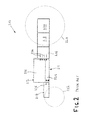
- a second form of known agricultural vehicle in the form of tractor 210 is shown having an engine 212 and a chassis indicated generally at 211.
- the chassis is formed by a front frame section 214, a clutch housing 216, a transmission housing 218 and a rear differential housing 220 which are attached to one another in a known manner.
- the vehicle 210 has front wheels 222 and rear wheels 224 which are driven and controlled in a conventional manner.
- the engine 212 is mainly formed from an engine block 226 and oil sump housing 228.
- the engine 212 is attached to the clutch housing 216 via rear bolts 234 and to the front frame section 214 by front bolts 236.
- This design has the advantage that the vehicle is easier to assemble during production due to the reduced number of parts. It has the disadvantage that the engine is relatively difficult to remove due to it being an integral part of the chassis 211.
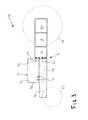
- an agricultural vehicle in the form of tractor 10 having an engine 12 and a chassis indicated generally at 11.
- the chassis is formed by a front frame section 14, a clutch housing 16, a transmission housing 18 and a rear differential housing 20.
- the clutch housing 16, transmission housing 18 and rear differential housing 20 are attached to one another in a known manner.
- the vehicle 10 has front wheels 22 and rear wheels 24 which are driven and controlled in a conventional manner.
- the engine 12 is formed from an engine block 26 and oil sump housing 28.
- the engine block 26 is attached to the front frame section 14 by way of bolts 30 situated at or near the front end 32 of the engine block 26.
- the engine block 26 is attached to the clutch housing 16 by way of bolts 34 situated at the rear end 36 of the engine block 26.
- the oil sump 28 is not connected to clutch housing 16.
- the front frame section 14 is attached to the clutch housing 16 by bolts 35.
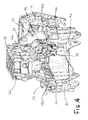
- the front frame section 14 is shown to have a first arm 14a and a second arm 14b situated on opposing sides of the oil sump housing 28.
- the engine block 26 contains an engine block housing 26a and a rear housing 26b.
- the rear housing 26b is attached to the rear of the engine block housing 26a in known manner.
- the rear housing 26b may form part of the flywheel housing or a cover to close the engine block housing 26a.
- the oil sump housing 28 is vertically screwed to engine block housing 26a by bolts or screws (not shown).
- the oil sump housing 28 is provided below the engine block 26 to form a reservoir for lubrication oil.
- a rear housing 26b forms part of the engine block housing 26a. Additional engine components, for example the cylinder head, are not shown for clarity.
- the rear housing 26b has a flange 37 which defines two or more holes 38 for receiving the rear bolts 36 to affix the engine 12 to the clutch housing 16. It will be appreciated that the bolts may be positioned at alternative positions on the interface between the engine 26 and the clutch housing 16 without departure from the invention.
- mounting brackets 40a, 40b which each receive a horizontal bolt 42 for attaching the bracket 40a, 40b to the engine block 26 and a vertical bolt 44 for attaching the bracket 40a, 40b to the arms 14a, 14b of the front frame section 14. This is shown in detail in Figure 5 .
- the engine 12 is initially affixed to the clutch housing 16 so that connection to successive parts of the driveline (for example the transmission), is correctly geometrically defined.
- the engine block 26 is attached to the front frame section 14.
- Brackets 40a, 40b ease the assembly process by allowing manufacturing tolerances to be accommodated without the need for shims (as is the case in the prior art).
- connection of the engine block 26 may be provided by using bores provided in engine block housing 26a and aligned in a longitudinal row which is parallel and external to threaded holes used to connect the oil sump housing 28 to engine block housing 26a by bolts or screws.
- manufacturing tolerances may be accommodated by using shims.
- the engine 12 is initially affixed to clutch housing 16 followed by the step of connecting the engine 12 to the front frame section 14.
- the clutch housing 16 and front frame section 14 may be assembled prior to attachment to the engine 12.
- the engine 12 may be attached to the front frame 14 followed by the subsequent attachment of the engine 26 to clutch housing 16.
- the invention offers a very flexible assembly with regards to the order in which engine 12, front frame 14 and transmission housing 16 are attached to each other during assembly. Furthermore, the engine 12 can be detached very simply from the chassis in order to undertake maintenance on the vehicle.
- the rear end of the chassis 11, 111, 211 is provided by a clutch housing 16, a transmission housing 18 and a rear differential housing 20.
- the transmission housing 18 may alternatively include the clutch housing 16 and/or rear differential housing 20 without departing from the scope of the invention.
Landscapes
- Engineering & Computer Science (AREA)
- Chemical & Material Sciences (AREA)
- Combustion & Propulsion (AREA)
- Transportation (AREA)
- Mechanical Engineering (AREA)
- Body Structure For Vehicles (AREA)
- Arrangement Of Transmissions (AREA)
Abstract
Description
- The present invention relates to agricultural vehicles and in particular, but not exclusively, to the construction of a frame and engine block for a tractor.
- It is common for agricultural vehicles, typically tractors, to have a modular construction in which the housing for the clutch, transmission and rear axle form an integral part of the frame.
- Typically the front part of the frame is defined either by the engine block itself or a separate front frame onto which the engine block is mounted.
- The mounting of the engine block onto a front frame which extends below the engine (also referred to as "frame concept") has major advantages as follows. Firstly, the weight of the vehicle is decreased as the oil sump does not form part of the structural chassis and can therefore be of a lightweight construction. Secondly, the concept allows for alternative engines to be readily mounted on a single chassis design. Thirdly, the engine can be of a lightweight design as it is not part of the structural chassis. Lastly, the chassis can be more easily adapted, for example to provide attachment means for a front loader, without altering the design of the engine. However, this concept also has a distinct disadvantage in that the relative movement between engine and chassis necessitates the use of flexible connections between the chassis and various components such as the driveline, air intake and exhaust ducts.
- A known alternative to the "frame concept" is the "block concept" in which the engine block forms an integral part of the frame. This solution has advantages in that the number of parts is reduced and the front frame is more compact. However, it also has disadvantages as follows. Firstly, disassembly of the frame for maintenance of the engine is more complex than in the frame concept. Secondly, the weight of the construction is increased as the engine must be designed to be very stiff. Thirdly, additional strain is applied to the engine block as it forms part of the structural chassis. Fourthly, the concept is less effective at isolating engine vibrations from the chassis than the frame concept. Lastly, attachment means for a front loader must be integrated into the oil sump, or alternatively, provided by an additional frame section requiring additional space.
- It is an object of the present invention to at least mitigate some of the above problems.
- According to a first aspect of the invention there is provided an agricultural vehicle having an engine mounted on a chassis,
the chassis including a clutch housing and/or transmission housing and a front frame section,
the engine including an engine block fixed to the chassis,
wherein the engine block is fixed to the front frame section only at a front end of the engine block, and the engine block is fixed to the transmission housing only at a rear end of the engine block. - Advantageously, the mounting of the engine block to the transmission housing and the front frame section provides a design which offers the major advantages of the known frame concept whilst eliminating or at least mitigating the disadvantages. In particular the advantages are as follows. Firstly, the engine can be easily disassembled as it does not form part of the chassis. Secondly, since the engine is not part of the chassis it is not required to transfer the load carried by the chassis and so it can therefore be designed with a light weight construction. Thirdly, there is very little relative movement between the engine and the chassis which allows for a simple connection therebetween.
- Preferably, a rear end of the front frame section is fixed to the transmission housing.
- Preferably, the engine block includes an oil sump housing free from connection to the front frame section and/or the transmission housing.
- Preferably, a rear face of the engine block is fixed to the clutch or transmission housing by bolts which lie substantially in the horizontal plane and are aligned with the forward direction of travel the vehicle, and preferably, the bolt heads face a rearward direction of travel of the vehicle. Note that the terms "bolt" and "screw" are used interchangeably and encompass all removable mechanical fixing means. Preferably, the engine block is fixed to the front frame section by way of a mounting bracket, which mounting bracket may be bolted to the front frame section with at least one bolt aligned substantially in the vertical plane and/or may be bolted to the engine block by at least one bolt aligned substantially in the horizontal plane and perpendicular to the forward direction of the vehicle.
- Preferably, the engine includes an oil sump housing attached to a lower face of the engine block.
- Preferably, the front frame section has a first arm and a second arm, and wherein the oil sump housing is positioned between the first and second arms.
- Preferably, the transmission housing comprises a clutch housing.
- Preferably, the chassis further comprises a transaxle fixed to a rear of the clutch housing.
- Embodiments of the invention will now be described, by way of example only, and with reference to the following drawings, in which:
-
Figure 1 is a schematic representation of a prior art agricultural vehicle; -
Figure 2 is a schematic representation of a further prior art agricultural vehicle; -
Figure 3 is a schematic representation of an agricultural vehicle according to the present invention; -
Figure 4 is an isometric sectioned view through the front frame and engine block of the vehicle ofFigure 3 ; and -
Figure 5 is front section view showing part of the chassis ofFigure 4 in greater detail. - In
Figure 1 a known agricultural vehicle in the form oftractor 110 is shown having anengine 112 and a chassis indicated generally at 111. The chassis is formed by afront frame section 114, aclutch housing 116, atransmission housing 118 and a rear differential housing 120 which are attached to one another in a known manner. Thevehicle 110 has front wheels 122 andrear wheels 124 which are driven and controlled in a conventional manner. - The
engine 112 includes anengine block 126 and oil sump housing 128. Attached or integrated to theengine block 126 arecompliant engine mounts 130 which provide a degree of compliancy between theengine block 126 and thefront frame section 114 by way of resilient members schematically indicated assprings 132. Thecompliant engine mounts 130 allows a degree of flex in thefront frame section 114 which in this prior art embodiment is not sufficiently rigid for the mounting of theengine block 126 directly to thefront frame section 114. - The embodiment has the advantage that the engine can be easily changed in the event of failure or maintenance. It has the disadvantage that a large
front frame section 114 and separate oil sump housing 128 must be provided. - Referring to
Figure 2 , a second form of known agricultural vehicle in the form oftractor 210 is shown having anengine 212 and a chassis indicated generally at 211. The chassis is formed by afront frame section 214, aclutch housing 216, atransmission housing 218 and a reardifferential housing 220 which are attached to one another in a known manner. Thevehicle 210 hasfront wheels 222 andrear wheels 224 which are driven and controlled in a conventional manner. - The
engine 212 is mainly formed from an engine block 226 andoil sump housing 228. Theengine 212 is attached to theclutch housing 216 viarear bolts 234 and to thefront frame section 214 byfront bolts 236. - This design has the advantage that the vehicle is easier to assemble during production due to the reduced number of parts. It has the disadvantage that the engine is relatively difficult to remove due to it being an integral part of the
chassis 211. - Referring to
Figure 3 , an agricultural vehicle in the form of tractor 10 according to the present invention is shown having anengine 12 and a chassis indicated generally at 11. The chassis is formed by afront frame section 14, aclutch housing 16, atransmission housing 18 and a reardifferential housing 20. Theclutch housing 16,transmission housing 18 and reardifferential housing 20 are attached to one another in a known manner. The vehicle 10 hasfront wheels 22 and rear wheels 24 which are driven and controlled in a conventional manner. - The
engine 12 is formed from anengine block 26 andoil sump housing 28. Theengine block 26 is attached to thefront frame section 14 by way ofbolts 30 situated at or near thefront end 32 of theengine block 26. Theengine block 26 is attached to theclutch housing 16 by way ofbolts 34 situated at therear end 36 of theengine block 26. Theoil sump 28 is not connected toclutch housing 16. Thefront frame section 14 is attached to theclutch housing 16 bybolts 35. - Turning now additionally to
Figures 4 and5 , thefront frame section 14 is shown to have a first arm 14a and a second arm 14b situated on opposing sides of theoil sump housing 28. - The
engine block 26 contains anengine block housing 26a and a rear housing 26b. The rear housing 26b is attached to the rear of theengine block housing 26a in known manner. The rear housing 26b may form part of the flywheel housing or a cover to close theengine block housing 26a. - The
oil sump housing 28 is vertically screwed toengine block housing 26a by bolts or screws (not shown). Theoil sump housing 28 is provided below theengine block 26 to form a reservoir for lubrication oil. - Alternative designs may be provided within the scope of the invention in which a rear housing 26b forms part of the
engine block housing 26a. Additional engine components, for example the cylinder head, are not shown for clarity. At the rear of theengine block 26, the rear housing 26b has aflange 37 which defines two ormore holes 38 for receiving therear bolts 36 to affix theengine 12 to theclutch housing 16. It will be appreciated that the bolts may be positioned at alternative positions on the interface between theengine 26 and theclutch housing 16 without departure from the invention. - At the front of the
engine block 26 are mountingbrackets 40a, 40b which each receive ahorizontal bolt 42 for attaching thebracket 40a, 40b to theengine block 26 and avertical bolt 44 for attaching thebracket 40a, 40b to the arms 14a, 14b of thefront frame section 14. This is shown in detail inFigure 5 . - During assembly, the
engine 12 is initially affixed to theclutch housing 16 so that connection to successive parts of the driveline (for example the transmission), is correctly geometrically defined. In a second assembly step, theengine block 26 is attached to thefront frame section 14.Brackets 40a, 40b ease the assembly process by allowing manufacturing tolerances to be accommodated without the need for shims (as is the case in the prior art). - Alternatively, the connection of the
engine block 26 may be provided by using bores provided inengine block housing 26a and aligned in a longitudinal row which is parallel and external to threaded holes used to connect theoil sump housing 28 toengine block housing 26a by bolts or screws. In this case, manufacturing tolerances may be accommodated by using shims. - In the described embodiment, the
engine 12 is initially affixed toclutch housing 16 followed by the step of connecting theengine 12 to thefront frame section 14. Alternatively, theclutch housing 16 andfront frame section 14 may be assembled prior to attachment to theengine 12. Furthermore, theengine 12 may be attached to thefront frame 14 followed by the subsequent attachment of theengine 26 toclutch housing 16. - In such a way, the invention offers a very flexible assembly with regards to the order in which
engine 12,front frame 14 andtransmission housing 16 are attached to each other during assembly. Furthermore, theengine 12 can be detached very simply from the chassis in order to undertake maintenance on the vehicle. - In the described embodiments the rear end of the
chassis 11, 111, 211 is provided by aclutch housing 16, atransmission housing 18 and a reardifferential housing 20. Thetransmission housing 18 may alternatively include theclutch housing 16 and/or reardifferential housing 20 without departing from the scope of the invention.
Claims (14)
- An agricultural vehicle (10) having an engine (12) mounted on a chassis (11),
the chassis including a clutch housing (16) and/or a transmission housing (18) and a front frame section (14),
the engine (12) including an engine block (26) fixed to the chassis (11), characterised in that the engine block (26) is fixed to the front frame section (14) only at a front end (32) of the engine block, and the engine block (26) is fixed to the clutch housing (16) or transmission housing (18) only at a rear end (36) of the engine block. - The vehicle of claim 1 wherein a rear end of the front frame section (14) is fixed to the transmission housing (18).
- The vehicle of claim 1 or 2 wherein the engine block (26) includes an oil sump housing (28) free from connection to the front frame section (14) and/or the transmission housing (18).
- The vehicle of claim 1, 2 or 3 wherein a rear face (36) of the engine block (26) is fixed to the clutch housing (16) by bolts (35) which lie substantially in the horizontal plane and are aligned with the forward direction of travel the vehicle.
- The vehicle of claim 4 wherein the bolt heads face a backward direction of travel of the vehicle.
- The vehicle of claim 1 wherein the engine block (26) is fixed to the front frame section (14) by way of a mounting bracket (40a, 40b).
- The vehicle of claim 6 wherein the mounting bracket (40b) is bolted to the front frame section (14b) with at least one bolt (44) aligned substantially in the vertical plane.
- The vehicle of claim 6 or 7 wherein the mounting bracket (40b) is bolted to the engine block (26) by at least one bolt (42) aligned substantially in the horizontal plane and perpendicular to the forward direction of the vehicle.
- The vehicle of claim 3 wherein the oil sump housing (28) is attached to a lower face of the engine block (26).
- The vehicle of claim 9 wherein the front frame section (14) has a first arm (14a) and a second arm (14b), and wherein the oil sump housing (28) is positioned between the first and second arms.
- The vehicle of claim 1 wherein the engine block (26) is fixed to the front frame section (14) by bolts (30) engaging through a vertical bore in the engine block and the front frame.
- The vehicle of claim 11 wherein said bores are aligned in a longitudinal row which is parallel and external to further bores provided to connect an oil sump housing (28) to the engine block (26).
- The vehicle of any preceding claim wherein the transmission housing (18) comprises the clutch housing (16).
- The vehicle of claim 13 wherein the chassis further comprises a transaxle (20) fixed to a rear of the clutch housing (16).
Applications Claiming Priority (1)
| Application Number | Priority Date | Filing Date | Title |
|---|---|---|---|
| GBGB1322786.3A GB201322786D0 (en) | 2013-12-20 | 2013-12-20 | Tractor frame |
Publications (2)
| Publication Number | Publication Date |
|---|---|
| EP2891568A1 true EP2891568A1 (en) | 2015-07-08 |
| EP2891568B1 EP2891568B1 (en) | 2020-01-01 |
Family
ID=50071316
Family Applications (1)
| Application Number | Title | Priority Date | Filing Date |
|---|---|---|---|
| EP14194995.8A Active EP2891568B1 (en) | 2013-12-20 | 2014-11-26 | Tractor frame |
Country Status (2)
| Country | Link |
|---|---|
| EP (1) | EP2891568B1 (en) |
| GB (1) | GB201322786D0 (en) |
Citations (3)
| Publication number | Priority date | Publication date | Assignee | Title |
|---|---|---|---|---|
| US3883099A (en) * | 1974-02-14 | 1975-05-13 | Caterpillar Tractor Co | Resilient engine mount with self-locating means |
| JPS6334225A (en) * | 1987-06-29 | 1988-02-13 | Kubota Ltd | Engine support structure for tractor |
| JPH08104147A (en) * | 1994-10-03 | 1996-04-23 | Seirei Ind Co Ltd | Anti-vibration structure of crawler tractor |
-
2013
- 2013-12-20 GB GBGB1322786.3A patent/GB201322786D0/en not_active Ceased
-
2014
- 2014-11-26 EP EP14194995.8A patent/EP2891568B1/en active Active
Patent Citations (3)
| Publication number | Priority date | Publication date | Assignee | Title |
|---|---|---|---|---|
| US3883099A (en) * | 1974-02-14 | 1975-05-13 | Caterpillar Tractor Co | Resilient engine mount with self-locating means |
| JPS6334225A (en) * | 1987-06-29 | 1988-02-13 | Kubota Ltd | Engine support structure for tractor |
| JPH08104147A (en) * | 1994-10-03 | 1996-04-23 | Seirei Ind Co Ltd | Anti-vibration structure of crawler tractor |
Also Published As
| Publication number | Publication date |
|---|---|
| EP2891568B1 (en) | 2020-01-01 |
| GB201322786D0 (en) | 2014-02-05 |
Similar Documents
| Publication | Publication Date | Title |
|---|---|---|
| US10501123B2 (en) | Vehicle chassis assembly | |
| US7905540B2 (en) | Modular architecture for combat tactical vehicle | |
| CN104203725B (en) | Rear wheel drive, plug-in hybrid electric vehicles modular subframe sub-assembly and method | |
| US20140367951A1 (en) | Suspension Module Having a Skidplate | |
| RU2009104319A (en) | AIRCRAFT ENGINE MOUNT CONTAINING TWO THRACKS WITH CROSS-LINK CONNECTOR | |
| US8151757B2 (en) | Oil pan/axle support | |
| JP2020131931A (en) | Vehicle driving unit | |
| GB2590387A (en) | Mount on inverter housing | |
| CA2800966C (en) | Steering knuckle for a vehicle | |
| CN208393041U (en) | A kind of motor compressor suspension vibration-proof structure | |
| KR20160089212A (en) | Agricultural vehicle and intake/cooling module assembling methods of the Agricultural vehicle | |
| CN106969075A (en) | A kind of elastic damping structure and connection method | |
| EP2891568B1 (en) | Tractor frame | |
| JP5387852B2 (en) | Support device for vehicle powertrain | |
| CN209870500U (en) | Tractor and its front bracket assembly | |
| JP2009298396A (en) | Device for mounting engine on frame of versatile vehicle | |
| KR102681926B1 (en) | Structure for mounting driving device and steering device to vehicle body | |
| GB2538166A (en) | External component mounting assembly for at least one axle of a comercial vehicle | |
| CN102874106B (en) | Vehicle chassis and engineering truck | |
| RU116825U1 (en) | VEHICLE MODULAR VEHICLE | |
| GB2449562A (en) | Vehicle front axle transmission mounting | |
| CN108819696A (en) | The longitudinal automobile power assembly of hydraulic mount after a kind of band | |
| CN202986828U (en) | Straightly-operational shift mechanism for manual gearbox and manual gearbox assembly and car | |
| CN205601590U (en) | Rearmounted rear -guard engine mounting | |
| JP5548004B2 (en) | Work vehicle |
Legal Events
| Date | Code | Title | Description |
|---|---|---|---|
| PUAI | Public reference made under article 153(3) epc to a published international application that has entered the european phase |
Free format text: ORIGINAL CODE: 0009012 |
|
| 17P | Request for examination filed |
Effective date: 20141126 |
|
| AK | Designated contracting states |
Kind code of ref document: A1 Designated state(s): AL AT BE BG CH CY CZ DE DK EE ES FI FR GB GR HR HU IE IS IT LI LT LU LV MC MK MT NL NO PL PT RO RS SE SI SK SM TR |
|
| AX | Request for extension of the european patent |
Extension state: BA ME |
|
| R17P | Request for examination filed (corrected) |
Effective date: 20160108 |
|
| RBV | Designated contracting states (corrected) |
Designated state(s): AL AT BE BG CH CY CZ DE DK EE ES FI FR GB GR HR HU IE IS IT LI LT LU LV MC MK MT NL NO PL PT RO RS SE SI SK SM TR |
|
| GRAP | Despatch of communication of intention to grant a patent |
Free format text: ORIGINAL CODE: EPIDOSNIGR1 |
|
| STAA | Information on the status of an ep patent application or granted ep patent |
Free format text: STATUS: GRANT OF PATENT IS INTENDED |
|
| RIC1 | Information provided on ipc code assigned before grant |
Ipc: B60K 5/12 20060101AFI20190711BHEP Ipc: B60K 5/02 20060101ALI20190711BHEP |
|
| INTG | Intention to grant announced |
Effective date: 20190801 |
|
| GRAS | Grant fee paid |
Free format text: ORIGINAL CODE: EPIDOSNIGR3 |
|
| GRAA | (expected) grant |
Free format text: ORIGINAL CODE: 0009210 |
|
| STAA | Information on the status of an ep patent application or granted ep patent |
Free format text: STATUS: THE PATENT HAS BEEN GRANTED |
|
| AK | Designated contracting states |
Kind code of ref document: B1 Designated state(s): AL AT BE BG CH CY CZ DE DK EE ES FI FR GB GR HR HU IE IS IT LI LT LU LV MC MK MT NL NO PL PT RO RS SE SI SK SM TR |
|
| REG | Reference to a national code |
Ref country code: GB Ref legal event code: FG4D |
|
| REG | Reference to a national code |
Ref country code: AT Ref legal event code: REF Ref document number: 1219354 Country of ref document: AT Kind code of ref document: T Effective date: 20200115 Ref country code: CH Ref legal event code: EP |
|
| REG | Reference to a national code |
Ref country code: IE Ref legal event code: FG4D |
|
| REG | Reference to a national code |
Ref country code: DE Ref legal event code: R096 Ref document number: 602014059217 Country of ref document: DE |
|
| REG | Reference to a national code |
Ref country code: NL Ref legal event code: MP Effective date: 20200101 |
|
| REG | Reference to a national code |
Ref country code: LT Ref legal event code: MG4D |
|
| PG25 | Lapsed in a contracting state [announced via postgrant information from national office to epo] |
Ref country code: NL Free format text: LAPSE BECAUSE OF FAILURE TO SUBMIT A TRANSLATION OF THE DESCRIPTION OR TO PAY THE FEE WITHIN THE PRESCRIBED TIME-LIMIT Effective date: 20200101 Ref country code: CZ Free format text: LAPSE BECAUSE OF FAILURE TO SUBMIT A TRANSLATION OF THE DESCRIPTION OR TO PAY THE FEE WITHIN THE PRESCRIBED TIME-LIMIT Effective date: 20200101 Ref country code: PT Free format text: LAPSE BECAUSE OF FAILURE TO SUBMIT A TRANSLATION OF THE DESCRIPTION OR TO PAY THE FEE WITHIN THE PRESCRIBED TIME-LIMIT Effective date: 20200527 Ref country code: RS Free format text: LAPSE BECAUSE OF FAILURE TO SUBMIT A TRANSLATION OF THE DESCRIPTION OR TO PAY THE FEE WITHIN THE PRESCRIBED TIME-LIMIT Effective date: 20200101 Ref country code: LT Free format text: LAPSE BECAUSE OF FAILURE TO SUBMIT A TRANSLATION OF THE DESCRIPTION OR TO PAY THE FEE WITHIN THE PRESCRIBED TIME-LIMIT Effective date: 20200101 Ref country code: NO Free format text: LAPSE BECAUSE OF FAILURE TO SUBMIT A TRANSLATION OF THE DESCRIPTION OR TO PAY THE FEE WITHIN THE PRESCRIBED TIME-LIMIT Effective date: 20200401 Ref country code: FI Free format text: LAPSE BECAUSE OF FAILURE TO SUBMIT A TRANSLATION OF THE DESCRIPTION OR TO PAY THE FEE WITHIN THE PRESCRIBED TIME-LIMIT Effective date: 20200101 |
|
| PG25 | Lapsed in a contracting state [announced via postgrant information from national office to epo] |
Ref country code: HR Free format text: LAPSE BECAUSE OF FAILURE TO SUBMIT A TRANSLATION OF THE DESCRIPTION OR TO PAY THE FEE WITHIN THE PRESCRIBED TIME-LIMIT Effective date: 20200101 Ref country code: IS Free format text: LAPSE BECAUSE OF FAILURE TO SUBMIT A TRANSLATION OF THE DESCRIPTION OR TO PAY THE FEE WITHIN THE PRESCRIBED TIME-LIMIT Effective date: 20200501 Ref country code: LV Free format text: LAPSE BECAUSE OF FAILURE TO SUBMIT A TRANSLATION OF THE DESCRIPTION OR TO PAY THE FEE WITHIN THE PRESCRIBED TIME-LIMIT Effective date: 20200101 Ref country code: SE Free format text: LAPSE BECAUSE OF FAILURE TO SUBMIT A TRANSLATION OF THE DESCRIPTION OR TO PAY THE FEE WITHIN THE PRESCRIBED TIME-LIMIT Effective date: 20200101 Ref country code: GR Free format text: LAPSE BECAUSE OF FAILURE TO SUBMIT A TRANSLATION OF THE DESCRIPTION OR TO PAY THE FEE WITHIN THE PRESCRIBED TIME-LIMIT Effective date: 20200402 Ref country code: BG Free format text: LAPSE BECAUSE OF FAILURE TO SUBMIT A TRANSLATION OF THE DESCRIPTION OR TO PAY THE FEE WITHIN THE PRESCRIBED TIME-LIMIT Effective date: 20200401 |
|
| REG | Reference to a national code |
Ref country code: DE Ref legal event code: R097 Ref document number: 602014059217 Country of ref document: DE |
|
| PG25 | Lapsed in a contracting state [announced via postgrant information from national office to epo] |
Ref country code: RO Free format text: LAPSE BECAUSE OF FAILURE TO SUBMIT A TRANSLATION OF THE DESCRIPTION OR TO PAY THE FEE WITHIN THE PRESCRIBED TIME-LIMIT Effective date: 20200101 Ref country code: SK Free format text: LAPSE BECAUSE OF FAILURE TO SUBMIT A TRANSLATION OF THE DESCRIPTION OR TO PAY THE FEE WITHIN THE PRESCRIBED TIME-LIMIT Effective date: 20200101 Ref country code: ES Free format text: LAPSE BECAUSE OF FAILURE TO SUBMIT A TRANSLATION OF THE DESCRIPTION OR TO PAY THE FEE WITHIN THE PRESCRIBED TIME-LIMIT Effective date: 20200101 Ref country code: DK Free format text: LAPSE BECAUSE OF FAILURE TO SUBMIT A TRANSLATION OF THE DESCRIPTION OR TO PAY THE FEE WITHIN THE PRESCRIBED TIME-LIMIT Effective date: 20200101 Ref country code: SM Free format text: LAPSE BECAUSE OF FAILURE TO SUBMIT A TRANSLATION OF THE DESCRIPTION OR TO PAY THE FEE WITHIN THE PRESCRIBED TIME-LIMIT Effective date: 20200101 Ref country code: EE Free format text: LAPSE BECAUSE OF FAILURE TO SUBMIT A TRANSLATION OF THE DESCRIPTION OR TO PAY THE FEE WITHIN THE PRESCRIBED TIME-LIMIT Effective date: 20200101 |
|
| PLBE | No opposition filed within time limit |
Free format text: ORIGINAL CODE: 0009261 |
|
| STAA | Information on the status of an ep patent application or granted ep patent |
Free format text: STATUS: NO OPPOSITION FILED WITHIN TIME LIMIT |
|
| REG | Reference to a national code |
Ref country code: AT Ref legal event code: MK05 Ref document number: 1219354 Country of ref document: AT Kind code of ref document: T Effective date: 20200101 |
|
| 26N | No opposition filed |
Effective date: 20201002 |
|
| PG25 | Lapsed in a contracting state [announced via postgrant information from national office to epo] |
Ref country code: AT Free format text: LAPSE BECAUSE OF FAILURE TO SUBMIT A TRANSLATION OF THE DESCRIPTION OR TO PAY THE FEE WITHIN THE PRESCRIBED TIME-LIMIT Effective date: 20200101 Ref country code: IT Free format text: LAPSE BECAUSE OF FAILURE TO SUBMIT A TRANSLATION OF THE DESCRIPTION OR TO PAY THE FEE WITHIN THE PRESCRIBED TIME-LIMIT Effective date: 20200101 |
|
| PG25 | Lapsed in a contracting state [announced via postgrant information from national office to epo] |
Ref country code: PL Free format text: LAPSE BECAUSE OF FAILURE TO SUBMIT A TRANSLATION OF THE DESCRIPTION OR TO PAY THE FEE WITHIN THE PRESCRIBED TIME-LIMIT Effective date: 20200101 Ref country code: SI Free format text: LAPSE BECAUSE OF FAILURE TO SUBMIT A TRANSLATION OF THE DESCRIPTION OR TO PAY THE FEE WITHIN THE PRESCRIBED TIME-LIMIT Effective date: 20200101 |
|
| PG25 | Lapsed in a contracting state [announced via postgrant information from national office to epo] |
Ref country code: MC Free format text: LAPSE BECAUSE OF FAILURE TO SUBMIT A TRANSLATION OF THE DESCRIPTION OR TO PAY THE FEE WITHIN THE PRESCRIBED TIME-LIMIT Effective date: 20200101 |
|
| REG | Reference to a national code |
Ref country code: CH Ref legal event code: PL |
|
| PG25 | Lapsed in a contracting state [announced via postgrant information from national office to epo] |
Ref country code: LU Free format text: LAPSE BECAUSE OF NON-PAYMENT OF DUE FEES Effective date: 20201126 |
|
| REG | Reference to a national code |
Ref country code: BE Ref legal event code: MM Effective date: 20201130 |
|
| PG25 | Lapsed in a contracting state [announced via postgrant information from national office to epo] |
Ref country code: CH Free format text: LAPSE BECAUSE OF NON-PAYMENT OF DUE FEES Effective date: 20201130 Ref country code: LI Free format text: LAPSE BECAUSE OF NON-PAYMENT OF DUE FEES Effective date: 20201130 |
|
| PG25 | Lapsed in a contracting state [announced via postgrant information from national office to epo] |
Ref country code: IE Free format text: LAPSE BECAUSE OF NON-PAYMENT OF DUE FEES Effective date: 20201126 |
|
| PG25 | Lapsed in a contracting state [announced via postgrant information from national office to epo] |
Ref country code: TR Free format text: LAPSE BECAUSE OF FAILURE TO SUBMIT A TRANSLATION OF THE DESCRIPTION OR TO PAY THE FEE WITHIN THE PRESCRIBED TIME-LIMIT Effective date: 20200101 Ref country code: MT Free format text: LAPSE BECAUSE OF FAILURE TO SUBMIT A TRANSLATION OF THE DESCRIPTION OR TO PAY THE FEE WITHIN THE PRESCRIBED TIME-LIMIT Effective date: 20200101 Ref country code: CY Free format text: LAPSE BECAUSE OF FAILURE TO SUBMIT A TRANSLATION OF THE DESCRIPTION OR TO PAY THE FEE WITHIN THE PRESCRIBED TIME-LIMIT Effective date: 20200101 |
|
| PG25 | Lapsed in a contracting state [announced via postgrant information from national office to epo] |
Ref country code: MK Free format text: LAPSE BECAUSE OF FAILURE TO SUBMIT A TRANSLATION OF THE DESCRIPTION OR TO PAY THE FEE WITHIN THE PRESCRIBED TIME-LIMIT Effective date: 20200101 Ref country code: AL Free format text: LAPSE BECAUSE OF FAILURE TO SUBMIT A TRANSLATION OF THE DESCRIPTION OR TO PAY THE FEE WITHIN THE PRESCRIBED TIME-LIMIT Effective date: 20200101 |
|
| PG25 | Lapsed in a contracting state [announced via postgrant information from national office to epo] |
Ref country code: BE Free format text: LAPSE BECAUSE OF NON-PAYMENT OF DUE FEES Effective date: 20201130 |
|
| P01 | Opt-out of the competence of the unified patent court (upc) registered |
Effective date: 20230518 |
|
| PGFP | Annual fee paid to national office [announced via postgrant information from national office to epo] |
Ref country code: DE Payment date: 20251119 Year of fee payment: 12 |
|
| PGFP | Annual fee paid to national office [announced via postgrant information from national office to epo] |
Ref country code: GB Payment date: 20251121 Year of fee payment: 12 |
|
| PGFP | Annual fee paid to national office [announced via postgrant information from national office to epo] |
Ref country code: FR Payment date: 20251125 Year of fee payment: 12 |