EP2891533A1 - Apparatus and method for adjusting and controlling the stacking-up layer manufacturing - Google Patents
Apparatus and method for adjusting and controlling the stacking-up layer manufacturing Download PDFInfo
- Publication number
- EP2891533A1 EP2891533A1 EP14187224.2A EP14187224A EP2891533A1 EP 2891533 A1 EP2891533 A1 EP 2891533A1 EP 14187224 A EP14187224 A EP 14187224A EP 2891533 A1 EP2891533 A1 EP 2891533A1
- Authority
- EP
- European Patent Office
- Prior art keywords
- module
- stacking
- powder
- controlling
- adjusting
- Prior art date
- Legal status (The legal status is an assumption and is not a legal conclusion. Google has not performed a legal analysis and makes no representation as to the accuracy of the status listed.)
- Granted
Links
Images




Classifications
-
- B—PERFORMING OPERATIONS; TRANSPORTING
- B29—WORKING OF PLASTICS; WORKING OF SUBSTANCES IN A PLASTIC STATE IN GENERAL
- B29C—SHAPING OR JOINING OF PLASTICS; SHAPING OF MATERIAL IN A PLASTIC STATE, NOT OTHERWISE PROVIDED FOR; AFTER-TREATMENT OF THE SHAPED PRODUCTS, e.g. REPAIRING
- B29C64/00—Additive manufacturing, i.e. manufacturing of three-dimensional [3D] objects by additive deposition, additive agglomeration or additive layering, e.g. by 3D printing, stereolithography or selective laser sintering
- B29C64/10—Processes of additive manufacturing
- B29C64/141—Processes of additive manufacturing using only solid materials
- B29C64/153—Processes of additive manufacturing using only solid materials using layers of powder being selectively joined, e.g. by selective laser sintering or melting
-
- B—PERFORMING OPERATIONS; TRANSPORTING
- B22—CASTING; POWDER METALLURGY
- B22F—WORKING METALLIC POWDER; MANUFACTURE OF ARTICLES FROM METALLIC POWDER; MAKING METALLIC POWDER; APPARATUS OR DEVICES SPECIALLY ADAPTED FOR METALLIC POWDER
- B22F10/00—Additive manufacturing of workpieces or articles from metallic powder
- B22F10/20—Direct sintering or melting
- B22F10/28—Powder bed fusion, e.g. selective laser melting [SLM] or electron beam melting [EBM]
-
- B—PERFORMING OPERATIONS; TRANSPORTING
- B22—CASTING; POWDER METALLURGY
- B22F—WORKING METALLIC POWDER; MANUFACTURE OF ARTICLES FROM METALLIC POWDER; MAKING METALLIC POWDER; APPARATUS OR DEVICES SPECIALLY ADAPTED FOR METALLIC POWDER
- B22F10/00—Additive manufacturing of workpieces or articles from metallic powder
- B22F10/30—Process control
-
- B—PERFORMING OPERATIONS; TRANSPORTING
- B29—WORKING OF PLASTICS; WORKING OF SUBSTANCES IN A PLASTIC STATE IN GENERAL
- B29C—SHAPING OR JOINING OF PLASTICS; SHAPING OF MATERIAL IN A PLASTIC STATE, NOT OTHERWISE PROVIDED FOR; AFTER-TREATMENT OF THE SHAPED PRODUCTS, e.g. REPAIRING
- B29C64/00—Additive manufacturing, i.e. manufacturing of three-dimensional [3D] objects by additive deposition, additive agglomeration or additive layering, e.g. by 3D printing, stereolithography or selective laser sintering
- B29C64/20—Apparatus for additive manufacturing; Details thereof or accessories therefor
-
- B—PERFORMING OPERATIONS; TRANSPORTING
- B29—WORKING OF PLASTICS; WORKING OF SUBSTANCES IN A PLASTIC STATE IN GENERAL
- B29C—SHAPING OR JOINING OF PLASTICS; SHAPING OF MATERIAL IN A PLASTIC STATE, NOT OTHERWISE PROVIDED FOR; AFTER-TREATMENT OF THE SHAPED PRODUCTS, e.g. REPAIRING
- B29C64/00—Additive manufacturing, i.e. manufacturing of three-dimensional [3D] objects by additive deposition, additive agglomeration or additive layering, e.g. by 3D printing, stereolithography or selective laser sintering
- B29C64/20—Apparatus for additive manufacturing; Details thereof or accessories therefor
- B29C64/264—Arrangements for irradiation
-
- C—CHEMISTRY; METALLURGY
- C04—CEMENTS; CONCRETE; ARTIFICIAL STONE; CERAMICS; REFRACTORIES
- C04B—LIME, MAGNESIA; SLAG; CEMENTS; COMPOSITIONS THEREOF, e.g. MORTARS, CONCRETE OR LIKE BUILDING MATERIALS; ARTIFICIAL STONE; CERAMICS; REFRACTORIES; TREATMENT OF NATURAL STONE
- C04B35/00—Shaped ceramic products characterised by their composition; Ceramics compositions; Processing powders of inorganic compounds preparatory to the manufacturing of ceramic products
- C04B35/622—Forming processes; Processing powders of inorganic compounds preparatory to the manufacturing of ceramic products
- C04B35/64—Burning or sintering processes
-
- C—CHEMISTRY; METALLURGY
- C04—CEMENTS; CONCRETE; ARTIFICIAL STONE; CERAMICS; REFRACTORIES
- C04B—LIME, MAGNESIA; SLAG; CEMENTS; COMPOSITIONS THEREOF, e.g. MORTARS, CONCRETE OR LIKE BUILDING MATERIALS; ARTIFICIAL STONE; CERAMICS; REFRACTORIES; TREATMENT OF NATURAL STONE
- C04B35/00—Shaped ceramic products characterised by their composition; Ceramics compositions; Processing powders of inorganic compounds preparatory to the manufacturing of ceramic products
- C04B35/622—Forming processes; Processing powders of inorganic compounds preparatory to the manufacturing of ceramic products
- C04B35/653—Processes involving a melting step
-
- B—PERFORMING OPERATIONS; TRANSPORTING
- B29—WORKING OF PLASTICS; WORKING OF SUBSTANCES IN A PLASTIC STATE IN GENERAL
- B29K—INDEXING SCHEME ASSOCIATED WITH SUBCLASSES B29B, B29C OR B29D, RELATING TO MOULDING MATERIALS OR TO MATERIALS FOR MOULDS, REINFORCEMENTS, FILLERS OR PREFORMED PARTS, e.g. INSERTS
- B29K2101/00—Use of unspecified macromolecular compounds as moulding material
-
- B—PERFORMING OPERATIONS; TRANSPORTING
- B29—WORKING OF PLASTICS; WORKING OF SUBSTANCES IN A PLASTIC STATE IN GENERAL
- B29K—INDEXING SCHEME ASSOCIATED WITH SUBCLASSES B29B, B29C OR B29D, RELATING TO MOULDING MATERIALS OR TO MATERIALS FOR MOULDS, REINFORCEMENTS, FILLERS OR PREFORMED PARTS, e.g. INSERTS
- B29K2105/00—Condition, form or state of moulded material or of the material to be shaped
- B29K2105/25—Solid
- B29K2105/251—Particles, powder or granules
-
- B—PERFORMING OPERATIONS; TRANSPORTING
- B33—ADDITIVE MANUFACTURING TECHNOLOGY
- B33Y—ADDITIVE MANUFACTURING, i.e. MANUFACTURING OF THREE-DIMENSIONAL [3D] OBJECTS BY ADDITIVE DEPOSITION, ADDITIVE AGGLOMERATION OR ADDITIVE LAYERING, e.g. BY 3D PRINTING, STEREOLITHOGRAPHY OR SELECTIVE LASER SINTERING
- B33Y10/00—Processes of additive manufacturing
-
- B—PERFORMING OPERATIONS; TRANSPORTING
- B33—ADDITIVE MANUFACTURING TECHNOLOGY
- B33Y—ADDITIVE MANUFACTURING, i.e. MANUFACTURING OF THREE-DIMENSIONAL [3D] OBJECTS BY ADDITIVE DEPOSITION, ADDITIVE AGGLOMERATION OR ADDITIVE LAYERING, e.g. BY 3D PRINTING, STEREOLITHOGRAPHY OR SELECTIVE LASER SINTERING
- B33Y30/00—Apparatus for additive manufacturing; Details thereof or accessories therefor
-
- Y—GENERAL TAGGING OF NEW TECHNOLOGICAL DEVELOPMENTS; GENERAL TAGGING OF CROSS-SECTIONAL TECHNOLOGIES SPANNING OVER SEVERAL SECTIONS OF THE IPC; TECHNICAL SUBJECTS COVERED BY FORMER USPC CROSS-REFERENCE ART COLLECTIONS [XRACs] AND DIGESTS
- Y02—TECHNOLOGIES OR APPLICATIONS FOR MITIGATION OR ADAPTATION AGAINST CLIMATE CHANGE
- Y02P—CLIMATE CHANGE MITIGATION TECHNOLOGIES IN THE PRODUCTION OR PROCESSING OF GOODS
- Y02P10/00—Technologies related to metal processing
- Y02P10/25—Process efficiency
Definitions
- Taiwan (International) Application Serial Number 102147539 filed on December 20, 2013 , the disclosure of which is hereby incorporated by reference herein in its entirety.
- the present disclosure relates to an apparatus and a method for adjusting and controlling the stacking-up layer manufacturing, and more particularly to the apparatus and the method for adjusting and controlling the material microstructure of stacking-up layer manufacturing product.
- the stacking-up layer or additive manufacturing method is a method for producing products with complicated configurations.
- powder bed fusion and direct energy deposition are two major application types of the metal additive manufacturing.
- the powder bed fusion of the additive manufacturing process comprises selective laser sintering (SLS), selective laser melting (SLM), direct metal laser sintering (DMLS), electron beam melting (EBM), and other relative techniques of powder bed fusion forming method.
- the direct energy deposition of the additive manufacturing process comprises laser engineering net shaping (LENS), laser metal deposition (LMD), 3D laser cladding, and other relative techniques of direct energy deposition forming method.
- the phase change of the material between the solid state and the liquid state and the crystallizing mechanism may greatly be affected by the energy of the heating source (such as laser or electron beam) and the scanning speed. If provided energy is excessive, material may be vaporized. On the other hand, if provided energy is insufficient, the melting or sintering process is insufficient. In addition, while the scanning speed of the energy beams is too fast or too slow, quality of the additive manufacturing may be degraded.
- the heating source such as laser or electron beam
- optimal process parameters for the current additive manufacturing, or said as the stacking-up layer manufacturing are limited in a specific range, and the crystallization (such as the crystal size and the crystal direction) of the material microstructure is usually uncontrollable by the variation of process parameters.
- the present disclosure is to provide an apparatus for adjusting and controlling the stacking-up layer manufacturing.
- the apparatus comprises:
- This disclosure further provides a method for adjusting and controlling the stacking-up layer manufacturing.
- the method comprises the steps of:
- This disclosure further provides a control method for an apparatus for adjusting and controlling the stacking-up layer manufacturing, in which the apparatus for adjusting and controlling the stacking-up layer manufacturing comprises a target, a powder providing unit for providing a powder onto the target, an energy generating unit for providing an energy beam and a magnetism unit for generating a magnetic field.
- the control method comprises the steps of:
- the first embodiment may comprise a powder providing unit 10, a magnetism unit 13, an energy generating unit 14 and a target 15.
- the target 15 may be a plate, a platform, a semi-finished product, or any the like. Also, the target 15 may be stationary or mobile.
- the powder providing unit 10 may be coupled on a top of the target 15.
- the powder providing unit 10 may provide a powder 102 to the surface (top surface) of the target 15 by spraying, depositing, rolling, leveling, laying, or a combination of at least two of the foregoing.
- the powder providing unit 10 may be structured as one selected from a group consisting of a knife-shape material providing module, a hopper material providing module, a spray material providing module, a feed-drum material providing module, and any the like.
- the foregoing material providing modules may be utilized to control the laying, depositing, rolling, leveling, or spraying of the powder.
- the powder providing unit 10 may have a knife-shape material providing module 100 and a first Y-axis displacement module 101.
- the knife-shape material providing module 100 and the first Y-axis displacement module 101 demonstrate simply an exemplary example for the powder providing unit, and it is understood that the embodying of the powder providing unit 10 shall not be limited to this pair of the knife-shape material providing module 100 and the single-axis displacement module 101.
- first Y-axis displacement module 101 may be coupled with the knife-shape material providing module 100 so as to allow the knife-shape material providing module 100 to perform a reciprocating motion along the Y axis.
- the apparatus for adjusting and controlling the stacking-up layer manufacturing may further comprise a displacement unit 11 that may comprise a second Y-axis displacement module 110, an X-axis displacement module 111 and a Z-axis displacement module 112.
- the second Y-axis displacement module 110 may be coupled with the knife-shape material providing module 100, the X-axis displacement module 111 may be coupled with the second Y-axis displacement module 110, and the Z-axis displacement module 112 may be coupled with the X-axis displacement module 111.
- the apparatus for adjusting and controlling the stacking-up layer manufacturing may further comprise an adjustment module 12 that may comprise a turning module 120, at least one protrusion module 121, at least one angular adjustment modules 122 and at least one tilt modules 123.
- the turning module 120 may be coupled with the Z-axis displacement module 112.
- the protrusion module 121 may be coupled on top of the turning module 120. It may have two protrusion modules 121, and may be located oppositely to each other. It may have two angular adjustment modules 122, and may be coupled on top of the respective protrusion module 121. It may have two tilt modules 123, and may be coupled top to the respective angular adjustment module 122.
- the magnetism unit 13 for generating a magnetic field 132 may have a first magnetic pair 130, or a combination of the first magnetic pair 130 and a second magnetic pair 131. In this embodiment, the magnetism unit 13 may provide a magnetic field 132, as shown in FIG.1 . In other embodiments, the magnetism unit 13 may alter the arrangement of the first magnetic pair 130 and the second magnetic pair 131, and may provide a static magnetic field, an alternative magnetic field or a pulse magnetic field. Details for these would be elucidated in later sections.
- the first magnetic pair 130 may be an electromagnetic member having two electromagnetic poles, or at least two electromagnetic members that each of the at least two electromagnetic members may be coupled with the respective tilt module 123.
- the second magnetic pair 131 may be an electromagnetic member having two electromagnetic poles, or at least two electromagnetic members for helping to vary the strength of the first magnetic pair 130.
- the first magnetic pair 130 and the second magnetic pair 131 may be coupled to the turning module 120.
- the first magnetic pair 130 and the second magnetic pair 131 may be integrally arranged in a surrounding manner or any manner the like. In this embodiment, the surrounding manner may be performed by a rectangular arrangement, referred to FIG.5 .
- the magnetic field 132 in this embodiment may be located in the area surrounded by the first magnetic pair 130 and the second magnetic pair 131.
- the second Y-axis displacement module 110 may allow the adjustment module 12 to perform reciprocating motion along the Y axis.
- the X-axis displacement module 111 may allow the adjustment module 12 to perform another reciprocating motion along the X axis
- the Z-axis displacement module 112 may allow the adjustment module 12 to perform a respective reciprocating motion along the Z axis.
- the turning module 120 may allow the magnetism unit 13 to rotate an angle about the Z axis.
- the protrusion module 121 may adjust the spacing between the two electromagnetic poles of the first magnetic pair 130; i.e. to control the distance between the two electromagnetic members.
- the angular adjustment module 122 may adjust the angling of the two electromagnetic poles of the first magnetic pair 130 with respect to the Y axis.
- the tilt module 123 may adjust the elevation angling of the two electromagnetic poles of the first magnetic pair 130 with respect to the Z axis.
- the energy generating unit 14, the adjustment module 12, and the magnetism unit 13 may be coupled on top of the target 15 in either a stationary or a mobile manner.
- the energy generating unit 14 may generate an energy beam 140, in which the energy beam 140 may be a laser beam, an electron beam, an electric arc, or a combination of at least two of the foregoing.
- the apparatus of this disclosure may be applied to selective laser sintering (SLS), selective laser melting (SLM), direct metal laser sintering (DMLS), or electron beam melting (EBM).
- FIG.6 a second embodiment of the apparatus for adjusting and controlling the stacking-up layer manufacturing of this disclosure is schematically shown.
- the major difference is that the powder providing unit 10A of the second embodiment may be selectively disconnected with the other elements, such as the displacement unit 11, the adjustment module 12, the magnetism unit 13, and the energy generating unit 14.
- the powder providing unit 10A may be movably coupled on top of the target for providing a powder 102A onto the surface of the target 15.
- the powder providing unit 10A here is embodied again as, but not limited to, a knife-shape material providing module.
- the powder providing unit 10A may be moved independently.
- This second embodiment of the apparatus of this disclosure can be applied to selective laser sintering (SLS), selective laser melting (SLM), direct metal laser sintering (DMLS), or electron beam melting (EBM).
- FIG.7 a third embodiment of the apparatus for adjusting and controlling the stacking-up layer manufacturing of this disclosure is schematically shown.
- the major difference in between is that the third embodiment has the energy generating unit 14B and the powder providing unit 10B to replace the energy generating unit 14 and the powder providing unit 10 of the first embodiment. Except for this change, all other elements of these two embodiments such as the displacement unit 11, the adjustment module 12, the magnetism unit 13, and the target 15 are the same.
- the powder providing unit 10B may be coupled with the energy generating unit 14B to provide the powder 102B onto the target 15.
- the powder providing unit 10B may be a hopper material providing module or a spray material providing module.
- the energy generating unit 14B may be movably coupled on top of the target 15, and may direct an energy beam 140B onto the surface of the target 15 so as to selectively melt or sinter a predetermined area of the powder into a melted or sintered state.
- the magnetism unit 13 may provide a magnetic field to the melted or sintered powder layer during the solidification process so as to control the material microstructures.
- the aforesaid magnetic field may be a static magnetic field, an alternative magnetic field, or a pulse magnetic field.
- the apparatus of this embodiment can be applied to a process of laser engineering net shaping (LENS), laser metal deposition (LMD), or 3D laser cladding.
- the apparatus may comprise a station 60, a powder providing unit 61, a displacement unit 62, a magnetism unit 63, and a target 64.
- the target 64 located inside the station 60 may perform a vertical reciprocation motion.
- the displacement unit 62 is located on top of the target 64 inside the station 60.
- the displacement unit 62 may replace the aforesaid first Y-axis displacement module 101 and the displacement unit 11 of the first embodiment of FIG.1 , or simply the first Y-axis displacement module 101 of FIG.1 .
- the powder providing unit 61 may be coupled with the displacement unit 62 to allow the powder providing unit 61 to perform a horizontal reciprocating motion with respect to the target 64.
- the powder providing unit 61 further has a knife-shape powder providing unit, and the magnetism unit 63 coupled with the powder providing unit 61 may also be located on top of the target 64.
- the powder providing unit 61 may provide a powder to the surface of the target 64 so as to form a layer of the powder on the target 64.
- the displacement unit 62 may move the powder providing unit 61.
- the displacement unit 62 may move the powder providing unit 61 away from the target 64, and move the magnetism unit 63 to a top position of the target 64; such that the magnetism unit 63 may move accordingly, via the displacement unit 62, with respect to the varying of the focus position of the energy generating unit.
- the magnetism unit 63 may be an electromagnetic member with two magnetic poles.
- the energy generating unit may provide an energy beam to the powder on the target surface.
- the magnetism unit 63 may provide a magnetic field to the powder on the target surface; such that the powder on the surface of the target may be heated by the energy beam and then be formed to a melted or sintered state.
- a mode, a direction, and a strength of the magnetic field are adjustable so as to control the material microstructure of a solidified layer after the solidification process.
- the magnetic field may be a static magnetic field, an alternative magnetic field or a pulse magnetic field.
- the powder providing unit is introduced again to provide the powder to the target 64, and the same manufacturing steps are performed again to form another solidified layer toping on the previous one.
- the aforesaid steps of forming the solidified layer are performed repeatedly, till a predetermined 3D product is formed by stacking a plurality of solidified layers.
- This embodiment of the apparatus of this disclosure may be applied to selective laser sintering (SLS), selective laser melting (SLM), direct metal laser sintering (DMLS), or electron beam melting (EBM).
- the magnetism unit for the apparatus for adjusting and controlling the stacking-up layer manufacturing may generate an alternative magnetic field, a pulse magnetic field, or a static magnetic field.
- the magnetism unit 20 may comprise at least one electromagnetic module 200, a cooling module 201, a switch module 202, and a power supply module 203.
- the electromagnetic module 200 may be coupled with the cooling module 201, and may be structured by an electromagnetic member having two magnetic poles, or at least one simple electromagnetic member.
- the cooling module 201 for cooling the electromagnetic module 200 that generates the magnetic field 204 may be selected from a group consisting of an air-cooling apparatus, an atmosphere cooling apparatus, a water cooling apparatus, a medium cooling apparatus, a thermoelectric cooling module, a metal heat-dissipating apparatus, a heat-dissipating fin apparatus, a honeycomb heat sink apparatus, and any the like.
- the switch module 202 may be coupled with the electromagnetic module 200, may switch the electromagnetic module 200 around an alternative mode, a pulse mode, and a DC static mode so as to generate an alternative magnetic field, a pulse magnetic field, and a static magnetic field, respectively.
- the power supply module 203 may be coupled with the electromagnetic module 200, may provide a voltage and a current to control the strength of the magnetic field 204 of the electromagnetic module 200.
- the magnetism unit 30 for generating the alternative magnetic field, the pulse magnetic field or the static magnetic field may be located on top of the target 33.
- the magnetism unit 30 comprises two electromagnetic modules 31, located oppositely to each other in a symmetric way. As these two electromagnetic modules 31 may be energized, a magnetic field 32 may be formed in between.
- the magnetism unit 40 for generating the alternative magnetic field, the pulse magnetic field or the static magnetic field is located on top of the target 44.
- the magnetism unit 40 may comprise an electromagnetic module 41, and two electromagnetic poles 42 located under the electromagnetic module 41 in a symmetric opposing manner. As the electromagnetic module 41 may be energized, a magnetic field 43 may be formed between the two electromagnetic poles 42.
- the magnetism unit 50 for generating the alternative magnetic field, the pulse magnetic field or the static magnetic field comprises two separate electromagnetic modules 51, each of which may be structured as a semi-circle to form a half of the circle.
- a magnetic field 52 may be formed in the circle, namely between the two electromagnetic modules 51.
- the electromagnetic module 51 may be treated as a magnetic pole, so that the induced magnetic field 52 is formed between these two pairing magnetic poles.
- the electromagnetic module may be embodied as, but not limited to, an electromagnet.
- An apparatus to employ this method for adjusting and controlling the stacking-up layer manufacturing may comprise a target, a powder providing unit for providing powders onto the target, an energy generating unit for providing an energy beam and a magnetism unit for generating a magnetic field.
- the method comprises the following steps.
- S1 Provide a powder onto a surface of the target thereon, in which the target may be selected from a group consisting of a plate, a platform, and a semi-finished product, and the powder may be selected from a group consisting of selected from a group consisting of a metal, an alloy, a metal-based composite, a polymer, a ceramic, a non-ferrous material, and any material formed by at least two of the foregoing materials
- the powder providing unit 10 may be coupled with the displacement unit, the adjustment module 12, the magnetism unit 13 or the energy generating unit 14, and may provide the powder 102 to the surface of the target 15.
- the powder providing unit 10 may provide the powder to the surface of the target 15 by a method selected from a group consisting of spraying, depositing, rolling, leveling, laying, and a combination of at least two of the foregoing.
- the powder providing unit 10A may provide the powder 102A by laying to the surface of the target 15.
- the powder providing unit 10B may be coupled with the energy generating unit 14B, and may provide the powder 102B by spraying to the surface of the target 15.
- the powder providing unit 61 may be coupled with the displacement unit 62, and may provide the powder to the surface of the target 64 via the horizontal reciprocating motion of the powder providing unit 61 with respect to the target 64.
- the energy generating unit 13 and the powder providing unit 10, 10A, 10B, 61 may be moved in a correlated manner or in an independent manner.
- S2 Direct an energy beam onto the powder on the surface of the target so as to melt or sinter a particular area of the powder, and may form a melted or sintered powder layer.
- the energy beam 140 may selectively heat the powder so as to have a particular area to form a melted or sintered powder layer.
- the method for the aforesaid melting or sintering may be selected from a group consisting of selective laser sintering (SLS), selective laser melting (SLM), direct metal laser sintering (DMLS), and electron beam melting (EBM).
- the energy beam 140 may selectively heat the powder in a particular area to form a melted or sintered powder layer.
- the energy beam 140 may selectively heat the powder in a particular area to form a melted or sintered powder layer.
- the energy beam may penetrate the spacing in the magnetism unit 63 so as to selectively melt or sinter the powder on the platform 64.
- S3 Provide a magnetic field to the melted or sintered powder layer, and thereby able to control the solidification of the melted or sintered powder layer.
- the magnetism unit 13 may provide the magnetic field 132 to the melted or sintered powder layer, so that the material microstructure may be controlled during the solidification of the melted or sintered powder layer.
- the magnetism unit 13 may provide a magnetic field 132 to the melted or sintered powder layer 102A, so that material microstructure may be controlled during the solidification of the melted or sintered powder layer.
- the magnetism unit 13 may provide a magnetic field 132 to the melted or sintered powder layer.
- the powder providing unit 10B is a spray material providing module located in the energy generating unit 14B. As the energy generating unit 14B heats the powder, the powder providing unit 10B keeps providing the powder 102B onto the surface of the target 15.
- the magnetism unit 63 may provide a magnetic field to the melted or sintered powder layer over the surface of the target 64.
- Steps S2 and S3 may be executed synchronously, or may be performed in order.
- Step S4 The melted or sintered powder layer is thus solidified into a solidified layer. Then, go back to perform Steps S1 through S3. According to the predetermined 3D sliced layers, the method keeps repeatedly performing Steps S1 through S3, till a plurality of the solidified layers may be accumulated or laminated to form the desired 3D product.
- the method for the aforesaid melting or sintering may be selected from a group consisting of selective laser sintering (SLS), selective laser melting (SLM), Direct metal laser sintering (DMLS), and electron beam melting (EBM).
- SLS selective laser sintering
- SLM selective laser melting
- DMLS Direct metal laser sintering
- EBM electron beam melting
- the aforesaid manufacturing process for forming the melted or sintered powder layer may be a process of laser engineering net shaping (LENS), laser metal deposition (LMD), or 3D laser cladding.
- LENS laser engineering net shaping
- LMD laser metal deposition
- 3D laser cladding 3D laser cladding
- this disclosure introduces the technique of controlling the crystal size by varying or controlling the magnetic field, such that the magnetic field applied upon the melted or sintered powder layer may be controlled to form satisfied microstructures in the solidified layers as well as in the 3D product.
- the magnetic field may be an alternative magnetic field, a pulse magnetic field, or a static magnetic field, and a strength of the magnetic field is approximately ranged from 0.001 Tesla (T) to 3,000 T.
- T 0.001 Tesla
- P B o J L sin ⁇ t
- P v P vo + kd - 1 / 2 in which P is the pressure of the electromagnetic vibrator, ⁇ is the alternative frequency, B o is the strength of the magnetic field, J is the induced current, and d is the crystal size.
- the pressure of the electromagnetic vibrator, the magnetic field, the induced current, and the alternative frequency are all correlated.
- the pressure of the electromagnetic vibrator is increased as well.
- Curve A demonstrates a typical Joule heating effect
- Curve B demonstrates the corresponding electromagnetic vibration
- Curve C is the sum of Curve A and Curve B.
- the apparatus for controlling the magnetic field in this disclosure may control the solidification of melted or sintered layers to vary the final microstructure.
- the product with complicated shape and controllable crystallization orientation by conventional techniques in the art may then be produced.
Landscapes
- Engineering & Computer Science (AREA)
- Chemical & Material Sciences (AREA)
- Materials Engineering (AREA)
- Manufacturing & Machinery (AREA)
- Physics & Mathematics (AREA)
- Optics & Photonics (AREA)
- Mechanical Engineering (AREA)
- Ceramic Engineering (AREA)
- Inorganic Chemistry (AREA)
- Structural Engineering (AREA)
- Organic Chemistry (AREA)
- Toxicology (AREA)
- Health & Medical Sciences (AREA)
- Automation & Control Theory (AREA)
- Plasma & Fusion (AREA)
- Powder Metallurgy (AREA)
- Composite Materials (AREA)
Abstract
Description
- The present application is based on, and claims priority from, Taiwan (International) Application Serial Number
102147539, filed on December 20, 2013 - The present disclosure relates to an apparatus and a method for adjusting and controlling the stacking-up layer manufacturing, and more particularly to the apparatus and the method for adjusting and controlling the material microstructure of stacking-up layer manufacturing product.
- Conventional manufacturing methods such as the casting can only provide products with fixed configurations. If there is a need for improving material properties (strength and surface hardness for example) of the product to meet various requirements, a further relevant heat treatment can be applied so as to form a homogeneous internal texture or to provide a controllable surface. If the need is to modify the configuration of the object, then some specific manufacture methods can also be available already in the art.
- The stacking-up layer or additive manufacturing method is a method for producing products with complicated configurations. Currently, among various additive manufacturing methods, powder bed fusion and direct energy deposition are two major application types of the metal additive manufacturing. The powder bed fusion of the additive manufacturing process comprises selective laser sintering (SLS), selective laser melting (SLM), direct metal laser sintering (DMLS), electron beam melting (EBM), and other relative techniques of powder bed fusion forming method. The direct energy deposition of the additive manufacturing process comprises laser engineering net shaping (LENS), laser metal deposition (LMD), 3D laser cladding, and other relative techniques of direct energy deposition forming method.
- In all the aforesaid additive manufacture methods, during the solidification process, the phase change of the material between the solid state and the liquid state and the crystallizing mechanism may greatly be affected by the energy of the heating source (such as laser or electron beam) and the scanning speed. If provided energy is excessive, material may be vaporized. On the other hand, if provided energy is insufficient, the melting or sintering process is insufficient. In addition, while the scanning speed of the energy beams is too fast or too slow, quality of the additive manufacturing may be degraded. Therefore, optimal process parameters for the current additive manufacturing, or said as the stacking-up layer manufacturing, are limited in a specific range, and the crystallization (such as the crystal size and the crystal direction) of the material microstructure is usually uncontrollable by the variation of process parameters.
- The present disclosure is to provide an apparatus for adjusting and controlling the stacking-up layer manufacturing. The apparatus comprises:
- a target;
- a powder providing unit, coupled on a top of the target, providing a powder to a surface of the target;
- an energy generating unit, coupled also on the top of the target, providing an energy beam to selectively heat the powder on the surface of the target to form a melted or sintered powder layer; and
- a magnetism unit, coupled also on the top of the target, providing a magnetic field to control solidification of the melted or sintered powder layer.
- This disclosure further provides a method for adjusting and controlling the stacking-up layer manufacturing. The method comprises the steps of:
- providing a powder onto a surface of a target thereon;
- directing an energy beam onto the powder on the surface of the target so as to melt or sinter a particular area of the powder to form a melted or sintered powder layer;
- applying a magnetic field to the melted or sintered powder layer so as to control solidification of the melted or sintered powder layer and further to form a corresponding solidified layer; and
- performing repeatedly the aforesaid three steps till a 3D product is formed by a sequence stacking with the solidified layers.
- This disclosure further provides a control method for an apparatus for adjusting and controlling the stacking-up layer manufacturing, in which the apparatus for adjusting and controlling the stacking-up layer manufacturing comprises a target, a powder providing unit for providing a powder onto the target, an energy generating unit for providing an energy beam and a magnetism unit for generating a magnetic field. The control method comprises the steps of:
- providing the powder onto a surface of the target;
- directing the energy beam onto the powder on the surface of the target so as to melt or sinter a particular area to form a melted or sintered powder layer;
- applying the magnetic field to the melted or sintered powder layer so as to control a solidification of the melted or sintered powder layer and further to form a corresponding solidified layer; and
- performing repeatedly the aforesaid three steps till a 3D product is formed by a sequence stacking with the solidified layers.
- Further scope of applicability of the present application will become more apparent from the detailed description given hereinafter. However, it should be understood that the detailed description and specific examples, while indicating exemplary embodiments of the disclosure, are given by way of illustration only, since various changes and modifications within the spirit and scope of the disclosure will become apparent to those skilled in the art from this detailed description.
- The present disclosure will become more fully understood from the detailed description given herein below and the accompanying drawings which are given by way of illustration only, and thus are not limitative of the present disclosure and wherein:
-
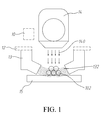
FIG. 1 is a schematic view of a first embodiment of the apparatus for adjusting and controlling the stacking-up layer manufacturing of this disclosure; -
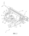
FIG.2 is a schematic perspective view ofFIG. 1 ; -
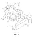
FIG.3 is a schematic enlarged view of thedisplacement unit 11, theadjustment module 12 and themagnetism unit 13 ofFIG.2 ; -
FIG.4 is a schematic exploded view ofFIG.3 ; -
FIG.5 is a schematic view of themagnetism unit 13 of the first embodiment of this disclosure; -
FIG.6 is a schematic view of a second embodiment of the apparatus for adjusting and controlling the stacking-up layer manufacturing of this disclosure; -
FIG.7 is a schematic view of a third embodiment of the apparatus for adjusting and controlling the stacking-up layer manufacturing of this disclosure; -
FIG.8 is a schematic perspective of a fourth embodiment of the apparatus for adjusting and controlling the stacking-up layer manufacturing of this disclosure; -
FIG.9 is a schematic view of an embodiment of the magnetism unit of this disclosure; -
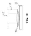
FIG. 10 is a schematic view of a further embodiment of the magnetism unit of this disclosure; -
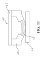
FIG.11 is a schematic view of a further embodiment of the magnetism unit of this disclosure; -
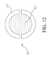
FIG. 12 is a schematic view of a further embodiment of the magnetism unit of this disclosure; -
FIG.13 is a flowchart of an embodiment of the method for adjusting and controlling the stacking-up layer manufacturing of this disclosure; -
FIG. 14 is a diagram showing the relationship between the crystal size and the magnetic field; and -
FIG. 15 is another illustration ofFIG. 14 , in which curve C is a combination of curves A and B ofFIG. 14 . - In the following detailed description, for purposes of explanation, numerous specific details are set forth in order to provide a thorough understanding of the disclosed embodiments. It will be apparent, however, that one or more embodiments may be practiced without these specific details. In other instances, well-known structures and devices are schematically shown in order to simplify the drawing.
- Referring now to
FIG.1 andFIG.2 , a schematic view and a corresponding perspective view of a first embodiment of the apparatus for adjusting and controlling the stacking-up layer manufacturing are shown, respectively. The first embodiment may comprise apowder providing unit 10, amagnetism unit 13, an energy generatingunit 14 and atarget 15. - In this disclosure the
target 15 may be a plate, a platform, a semi-finished product, or any the like. Also, thetarget 15 may be stationary or mobile. - The
powder providing unit 10 may be coupled on a top of thetarget 15. Thepowder providing unit 10 may provide apowder 102 to the surface (top surface) of thetarget 15 by spraying, depositing, rolling, leveling, laying, or a combination of at least two of the foregoing. In addition, thepowder providing unit 10 may be structured as one selected from a group consisting of a knife-shape material providing module, a hopper material providing module, a spray material providing module, a feed-drum material providing module, and any the like. The foregoing material providing modules may be utilized to control the laying, depositing, rolling, leveling, or spraying of the powder. - As shown in
FIG.2 , thepowder providing unit 10 may have a knife-shapematerial providing module 100 and a first Y-axis displacement module 101. In this first embodiment, the knife-shapematerial providing module 100 and the first Y-axis displacement module 101 demonstrate simply an exemplary example for the powder providing unit, and it is understood that the embodying of thepowder providing unit 10 shall not be limited to this pair of the knife-shapematerial providing module 100 and the single-axis displacement module 101. Anyway, in this embodiment, first Y-axis displacement module 101 may be coupled with the knife-shapematerial providing module 100 so as to allow the knife-shapematerial providing module 100 to perform a reciprocating motion along the Y axis. - Referring to
FIG.2 ,FIG.3 andFIG.4 , the apparatus for adjusting and controlling the stacking-up layer manufacturing may further comprise adisplacement unit 11 that may comprise a second Y-axis displacement module 110, anX-axis displacement module 111 and a Z-axis displacement module 112. - The second Y-
axis displacement module 110 may be coupled with the knife-shapematerial providing module 100, theX-axis displacement module 111 may be coupled with the second Y-axis displacement module 110, and the Z-axis displacement module 112 may be coupled with theX-axis displacement module 111. - The apparatus for adjusting and controlling the stacking-up layer manufacturing may further comprise an
adjustment module 12 that may comprise aturning module 120, at least oneprotrusion module 121, at least oneangular adjustment modules 122 and at least onetilt modules 123. - The
turning module 120 may be coupled with the Z-axis displacement module 112. Theprotrusion module 121 may be coupled on top of theturning module 120. It may have twoprotrusion modules 121, and may be located oppositely to each other. It may have twoangular adjustment modules 122, and may be coupled on top of therespective protrusion module 121. It may have twotilt modules 123, and may be coupled top to the respectiveangular adjustment module 122. - The
magnetism unit 13 for generating amagnetic field 132 may have a firstmagnetic pair 130, or a combination of the firstmagnetic pair 130 and a secondmagnetic pair 131. In this embodiment, themagnetism unit 13 may provide amagnetic field 132, as shown inFIG.1 . In other embodiments, themagnetism unit 13 may alter the arrangement of the firstmagnetic pair 130 and the secondmagnetic pair 131, and may provide a static magnetic field, an alternative magnetic field or a pulse magnetic field. Details for these would be elucidated in later sections. - The first
magnetic pair 130 may be an electromagnetic member having two electromagnetic poles, or at least two electromagnetic members that each of the at least two electromagnetic members may be coupled with therespective tilt module 123. - The second
magnetic pair 131 may be an electromagnetic member having two electromagnetic poles, or at least two electromagnetic members for helping to vary the strength of the firstmagnetic pair 130. In addition, the firstmagnetic pair 130 and the secondmagnetic pair 131 may be coupled to theturning module 120. The firstmagnetic pair 130 and the secondmagnetic pair 131 may be integrally arranged in a surrounding manner or any manner the like. In this embodiment, the surrounding manner may be performed by a rectangular arrangement, referred toFIG.5 . Themagnetic field 132 in this embodiment may be located in the area surrounded by the firstmagnetic pair 130 and the secondmagnetic pair 131. - As mentioned above, the second Y-
axis displacement module 110 may allow theadjustment module 12 to perform reciprocating motion along the Y axis. Similarly, theX-axis displacement module 111 may allow theadjustment module 12 to perform another reciprocating motion along the X axis, and the Z-axis displacement module 112 may allow theadjustment module 12 to perform a respective reciprocating motion along the Z axis. - The
turning module 120 may allow themagnetism unit 13 to rotate an angle about the Z axis. - The
protrusion module 121 may adjust the spacing between the two electromagnetic poles of the firstmagnetic pair 130; i.e. to control the distance between the two electromagnetic members. - The
angular adjustment module 122 may adjust the angling of the two electromagnetic poles of the firstmagnetic pair 130 with respect to the Y axis. - The
tilt module 123 may adjust the elevation angling of the two electromagnetic poles of the firstmagnetic pair 130 with respect to the Z axis. - Referred to
FIG.1 , theenergy generating unit 14, theadjustment module 12, and themagnetism unit 13 may be coupled on top of thetarget 15 in either a stationary or a mobile manner. Theenergy generating unit 14 may generate anenergy beam 140, in which theenergy beam 140 may be a laser beam, an electron beam, an electric arc, or a combination of at least two of the foregoing. The apparatus of this disclosure may be applied to selective laser sintering (SLS), selective laser melting (SLM), direct metal laser sintering (DMLS), or electron beam melting (EBM). - Referring now to
FIG.6 , a second embodiment of the apparatus for adjusting and controlling the stacking-up layer manufacturing of this disclosure is schematically shown. By comparing this second embodiment to the aforesaid first embodiment, the major difference is that thepowder providing unit 10A of the second embodiment may be selectively disconnected with the other elements, such as thedisplacement unit 11, theadjustment module 12, themagnetism unit 13, and theenergy generating unit 14. - In this second embodiment, the
powder providing unit 10A may be movably coupled on top of the target for providing apowder 102A onto the surface of thetarget 15. Thepowder providing unit 10A here is embodied again as, but not limited to, a knife-shape material providing module. In addition, thepowder providing unit 10A may be moved independently. This second embodiment of the apparatus of this disclosure can be applied to selective laser sintering (SLS), selective laser melting (SLM), direct metal laser sintering (DMLS), or electron beam melting (EBM). - Referring now to
FIG.7 , a third embodiment of the apparatus for adjusting and controlling the stacking-up layer manufacturing of this disclosure is schematically shown. By comparing this third embodiment to the aforesaid first embodiment, the major difference in between is that the third embodiment has theenergy generating unit 14B and thepowder providing unit 10B to replace theenergy generating unit 14 and thepowder providing unit 10 of the first embodiment. Except for this change, all other elements of these two embodiments such as thedisplacement unit 11, theadjustment module 12, themagnetism unit 13, and thetarget 15 are the same. - In this second embodiment, the
powder providing unit 10B may be coupled with theenergy generating unit 14B to provide thepowder 102B onto thetarget 15. Thepowder providing unit 10B may be a hopper material providing module or a spray material providing module. Theenergy generating unit 14B may be movably coupled on top of thetarget 15, and may direct anenergy beam 140B onto the surface of thetarget 15 so as to selectively melt or sinter a predetermined area of the powder into a melted or sintered state. - The
magnetism unit 13 may provide a magnetic field to the melted or sintered powder layer during the solidification process so as to control the material microstructures. The aforesaid magnetic field may be a static magnetic field, an alternative magnetic field, or a pulse magnetic field. The apparatus of this embodiment can be applied to a process of laser engineering net shaping (LENS), laser metal deposition (LMD), or 3D laser cladding. - Referring now to
FIG.8 , a fourth embodiment of the apparatus for adjusting and controlling the stacking-up layer manufacturing of this disclosure is schematically shown in this embodiment, the apparatus may comprise astation 60, apowder providing unit 61, adisplacement unit 62, amagnetism unit 63, and atarget 64. - The
target 64 located inside thestation 60 may perform a vertical reciprocation motion. Thedisplacement unit 62 is located on top of thetarget 64 inside thestation 60. In this embodiment, thedisplacement unit 62 may replace the aforesaid first Y-axis displacement module 101 and thedisplacement unit 11 of the first embodiment ofFIG.1 , or simply the first Y-axis displacement module 101 ofFIG.1 . - The
powder providing unit 61 may be coupled with thedisplacement unit 62 to allow thepowder providing unit 61 to perform a horizontal reciprocating motion with respect to thetarget 64. In this embodiment, thepowder providing unit 61 further has a knife-shape powder providing unit, and themagnetism unit 63 coupled with thepowder providing unit 61 may also be located on top of thetarget 64. - In
FIG.8 , though the aforesaid energy generating unit is not configured, yet it should be understood that lots of common elements or interchangeable elements prevail among these embodiments of the present disclosure. - Referring now to
FIG.8 , thepowder providing unit 61 may provide a powder to the surface of thetarget 64 so as to form a layer of the powder on thetarget 64. - The
displacement unit 62 may move thepowder providing unit 61. In particular, thedisplacement unit 62 may move thepowder providing unit 61 away from thetarget 64, and move themagnetism unit 63 to a top position of thetarget 64; such that themagnetism unit 63 may move accordingly, via thedisplacement unit 62, with respect to the varying of the focus position of the energy generating unit. In this embodiment, themagnetism unit 63 may be an electromagnetic member with two magnetic poles. - The energy generating unit may provide an energy beam to the powder on the target surface. The
magnetism unit 63 may provide a magnetic field to the powder on the target surface; such that the powder on the surface of the target may be heated by the energy beam and then be formed to a melted or sintered state. During a solidification process of the melted or sintered powder layer, a mode, a direction, and a strength of the magnetic field are adjustable so as to control the material microstructure of a solidified layer after the solidification process. - In this embodiment, the magnetic field may be a static magnetic field, an alternative magnetic field or a pulse magnetic field.
- As long as the solidified layer is formed, the
target 64 was lowered by a predetermined distance, then the powder providing unit is introduced again to provide the powder to thetarget 64, and the same manufacturing steps are performed again to form another solidified layer toping on the previous one. According to this disclosure, the aforesaid steps of forming the solidified layer are performed repeatedly, till a predetermined 3D product is formed by stacking a plurality of solidified layers. This embodiment of the apparatus of this disclosure may be applied to selective laser sintering (SLS), selective laser melting (SLM), direct metal laser sintering (DMLS), or electron beam melting (EBM). - Referring now to
FIG.9 , a schematic view of an embodiment of themagnetism unit 20 of this disclosure is schematically shown. According to the disclosure, the magnetism unit for the apparatus for adjusting and controlling the stacking-up layer manufacturing may generate an alternative magnetic field, a pulse magnetic field, or a static magnetic field. Themagnetism unit 20 may comprise at least oneelectromagnetic module 200, acooling module 201, aswitch module 202, and apower supply module 203. - The
electromagnetic module 200, may be coupled with thecooling module 201, and may be structured by an electromagnetic member having two magnetic poles, or at least one simple electromagnetic member. - The
cooling module 201 for cooling theelectromagnetic module 200 that generates themagnetic field 204 may be selected from a group consisting of an air-cooling apparatus, an atmosphere cooling apparatus, a water cooling apparatus, a medium cooling apparatus, a thermoelectric cooling module, a metal heat-dissipating apparatus, a heat-dissipating fin apparatus, a honeycomb heat sink apparatus, and any the like. - The
switch module 202, may be coupled with theelectromagnetic module 200, may switch theelectromagnetic module 200 around an alternative mode, a pulse mode, and a DC static mode so as to generate an alternative magnetic field, a pulse magnetic field, and a static magnetic field, respectively. - The
power supply module 203, may be coupled with theelectromagnetic module 200, may provide a voltage and a current to control the strength of themagnetic field 204 of theelectromagnetic module 200. - Referring now to
FIG.10 , a schematic view of another embodiment of themagnetism unit 30 of this disclosure is shown. In this embodiment, themagnetism unit 30 for generating the alternative magnetic field, the pulse magnetic field or the static magnetic field may be located on top of thetarget 33. Themagnetism unit 30 comprises twoelectromagnetic modules 31, located oppositely to each other in a symmetric way. As these twoelectromagnetic modules 31 may be energized, amagnetic field 32 may be formed in between. - Referring now to
FIG. 11 , a schematic view of a further embodiment of themagnetism unit 40 of this disclosure is shown. In this embodiment, themagnetism unit 40 for generating the alternative magnetic field, the pulse magnetic field or the static magnetic field is located on top of thetarget 44. Themagnetism unit 40 may comprise anelectromagnetic module 41, and twoelectromagnetic poles 42 located under theelectromagnetic module 41 in a symmetric opposing manner. As theelectromagnetic module 41 may be energized, amagnetic field 43 may be formed between the twoelectromagnetic poles 42. - Referring now to
FIG. 12 , a schematic view of one more embodiment of themagnetism unit 50 of this disclosure is shown. In this embodiment, themagnetism unit 50 for generating the alternative magnetic field, the pulse magnetic field or the static magnetic field comprises two separateelectromagnetic modules 51, each of which may be structured as a semi-circle to form a half of the circle. As theelectromagnetic modules 51 is energized, amagnetic field 52 may be formed in the circle, namely between the twoelectromagnetic modules 51. In this embodiment, theelectromagnetic module 51 may be treated as a magnetic pole, so that the inducedmagnetic field 52 is formed between these two pairing magnetic poles. - In all of the aforesaid embodiments of the magnetism units, the electromagnetic module may be embodied as, but not limited to, an electromagnet.
- Referring now to
FIG. 13 , a flowchart of an embodiment of the method for adjusting and controlling the stacking-up layer manufacturing of this disclosure is shown. An apparatus to employ this method for adjusting and controlling the stacking-up layer manufacturing may comprise a target, a powder providing unit for providing powders onto the target, an energy generating unit for providing an energy beam and a magnetism unit for generating a magnetic field. The method comprises the following steps. - S1: Provide a powder onto a surface of the target thereon, in which the target may be selected from a group consisting of a plate, a platform, and a semi-finished product, and the powder may be selected from a group consisting of selected from a group consisting of a metal, an alloy, a metal-based composite, a polymer, a ceramic, a non-ferrous material, and any material formed by at least two of the foregoing materials
- In the first embodiment of the apparatus shown in
FIG.1 , thepowder providing unit 10 may be coupled with the displacement unit, theadjustment module 12, themagnetism unit 13 or theenergy generating unit 14, and may provide thepowder 102 to the surface of thetarget 15. In the embodiment of the method, thepowder providing unit 10 may provide the powder to the surface of thetarget 15 by a method selected from a group consisting of spraying, depositing, rolling, leveling, laying, and a combination of at least two of the foregoing. - In the second embodiment of the apparatus shown in
FIG.6 , thepowder providing unit 10A may provide thepowder 102A by laying to the surface of thetarget 15. - In the third embodiment of the apparatus shown in
FIG.7 , thepowder providing unit 10B, may be coupled with theenergy generating unit 14B, and may provide thepowder 102B by spraying to the surface of thetarget 15. - In the fourth embodiment of the apparatus shown in
FIG.8 , thepowder providing unit 61, may be coupled with thedisplacement unit 62, and may provide the powder to the surface of thetarget 64 via the horizontal reciprocating motion of thepowder providing unit 61 with respect to thetarget 64. - In the aforesaid embodiments of the
targets energy generating unit 13 and thepowder providing unit - S2: Direct an energy beam onto the powder on the surface of the target so as to melt or sinter a particular area of the powder, and may form a melted or sintered powder layer.
- In the first embodiment of the apparatus shown in
FIG.1 , while theenergy generating unit 14 provides theenergy beam 140 to thepowder 102, theenergy beam 140 may selectively heat the powder so as to have a particular area to form a melted or sintered powder layer. The method for the aforesaid melting or sintering may be selected from a group consisting of selective laser sintering (SLS), selective laser melting (SLM), direct metal laser sintering (DMLS), and electron beam melting (EBM). - In the second embodiment of the apparatus shown in
FIG.6 , while theenergy generating unit 14 provides theenergy beam 140 to thepowder 102A, theenergy beam 140 may selectively heat the powder in a particular area to form a melted or sintered powder layer. - In the third embodiment of the apparatus shown in
FIG.7 , while theenergy generating unit 14B provides theenergy beam 140B to the powder on the surface of the target, theenergy beam 140 may selectively heat the powder in a particular area to form a melted or sintered powder layer. - In the fourth embodiment of the apparatus shown in
FIG.8 , though the location of the energy generating unit is not shown, yet it may be understood that the energy beam may penetrate the spacing in themagnetism unit 63 so as to selectively melt or sinter the powder on theplatform 64. - S3: Provide a magnetic field to the melted or sintered powder layer, and thereby able to control the solidification of the melted or sintered powder layer.
- In the first embodiment of the apparatus shown in
FIG.1 , themagnetism unit 13 may provide themagnetic field 132 to the melted or sintered powder layer, so that the material microstructure may be controlled during the solidification of the melted or sintered powder layer. - In the second embodiment of the apparatus shown in
FIG.6 , themagnetism unit 13 may provide amagnetic field 132 to the melted or sinteredpowder layer 102A, so that material microstructure may be controlled during the solidification of the melted or sintered powder layer. - In the third embodiment of the apparatus shown in
FIG.7 , themagnetism unit 13 may provide amagnetic field 132 to the melted or sintered powder layer. In his embodiment, thepowder providing unit 10B is a spray material providing module located in theenergy generating unit 14B. As theenergy generating unit 14B heats the powder, thepowder providing unit 10B keeps providing thepowder 102B onto the surface of thetarget 15. - In the fourth embodiment of the apparatus shown in
FIG.8 , themagnetism unit 63 may provide a magnetic field to the melted or sintered powder layer over the surface of thetarget 64. - In this disclosure, the aforesaid Steps S2 and S3 may be executed synchronously, or may be performed in order.
- S4: The melted or sintered powder layer is thus solidified into a solidified layer. Then, go back to perform Steps S1 through S3. According to the predetermined 3D sliced layers, the method keeps repeatedly performing Steps S1 through S3, till a plurality of the solidified layers may be accumulated or laminated to form the desired 3D product.
- In the first, second and fourth embodiments of the apparatus shown respectively in
FIG.1 ,FIG.6 andFIG.8 , the method for the aforesaid melting or sintering may be selected from a group consisting of selective laser sintering (SLS), selective laser melting (SLM), Direct metal laser sintering (DMLS), and electron beam melting (EBM). - In the third embodiment of the apparatus shown in
FIG.7 , the aforesaid manufacturing process for forming the melted or sintered powder layer may be a process of laser engineering net shaping (LENS), laser metal deposition (LMD), or 3D laser cladding. - In summary, this disclosure introduces the technique of controlling the crystal size by varying or controlling the magnetic field, such that the magnetic field applied upon the melted or sintered powder layer may be controlled to form satisfied microstructures in the solidified layers as well as in the 3D product.
- In this disclosure, the magnetic field may be an alternative magnetic field, a pulse magnetic field, or a static magnetic field, and a strength of the magnetic field is approximately ranged from 0.001 Tesla (T) to 3,000 T. Following equations demonstrate, typically but not limited to, a possible physical mechanism of the solidification under the alternative magnetic field or the pulse magnetic field.


in which P is the pressure of the electromagnetic vibrator, ω is the alternative frequency, Bo is the strength of the magnetic field, J is the induced current, and d is the crystal size. - Obviously, under the influence of the alternative magnetic field or the pulse magnetic field, the pressure of the electromagnetic vibrator, the magnetic field, the induced current, and the alternative frequency are all correlated. In particular, as the strength of the magnetic field and the alternative frequency increase, the pressure of the electromagnetic vibrator is increased as well.
- Refer now to
FIG.14 and FIG. 15 , in which Curve A demonstrates a typical Joule heating effect, Curve B demonstrates the corresponding electromagnetic vibration, and Curve C is the sum of Curve A and Curve B. - Under the efforts of the electromagnetic vibration and the Joule heating effect under the alternative magnetic field or the pulse magnetic field, as the magnetic field is initiated, the effect of the electromagnetic vibration upon the magnetic field is significant. The grain growth may be restricted and form a fine grain or amorphous microstructure as the strength of magnetic field increase. However, as the magnetic field is too strong, the Joule heating effect may prolong the required cooling time during the solidification, such that the crystal size may increase and form a coarse grain. The effects of the microstructure variation may be dependent to the material properties. Thus, the apparatus for controlling the magnetic field in this disclosure may control the solidification of melted or sintered layers to vary the final microstructure.
- Following equations demonstrate, typically but not limited to, a possible physical mechanism of the solidification under the static magnetic field.

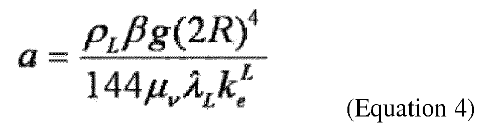
in which ρL is the density of the liquid-phase metal, β is the expansion coefficient, g is gravity acceleration, R is he radius of the melted body, µv is the viscosity coefficient, λL is the heat-transfer coefficient, and vI is the velocity of the liquid-phase metal. - Apparently, as velocity of the liquid-phase metal driven by the static electromagnetic field is larger than the shifting speed of the solid-liquid interface during the solidification, the crystallization orientation may be affected and driven by the static electromagnetic field. At this time, the instant shifting speed of the solid-liquid interface in the liquid-phase metal is called the critical speed. In the case that the shifting speed of the solid-liquid interface driven by the static electromagnetic field is larger than the critical speed, the crystallization direction of the microstructure of the material in the stacking-up layer manufacturing would be driven by the magnetic field.
- By providing the apparatus and the method for adjusting and controlling the stacking-up layer manufacturing in accordance with the foregoing disclosure, the product with complicated shape and controllable crystallization orientation by conventional techniques in the art may then be produced.
- With respect to the above description then, it is to be realized that the optimum factors relationships for the parts of the disclosure, to comprise variations in size, materials, shape, form, function and manner of operation, assembly and use, are deemed readily apparent and obvious to one skilled in the art, and all equivalent relationships to those illustrated in the drawings and described in the specification are intended to be encompassed by the present disclosure.
Claims (16)
- An apparatus for adjusting and controlling the stacking-up layer manufacturing, comprising:a target;a powder providing unit, coupled on thetop of the target, providing a powder to the surface of the target;an energy generating unit, coupled also on the top of the target, providing the energy beam to selectively heat the powder on the surface of the target to form a melted or sintered powder layer; anda magnetism unit, coupled also on the top of the target, providing a magnetic field to control the solidification of the melted or sintered powder layer.
- The apparatus for adjusting and controlling the stacking-up layer manufacturing of claim 1, wherein the target is selected from a group consisting of a plate, a platform, and a semi-finished product.
- The apparatus for adjusting and controlling the stacking-up layer manufacturing of claim 1, wherein the energy beam is selected from a group consisting of a laser beam, an electron beam, an electric arc, and a combination thereof.
- The apparatus for adjusting and controlling the stacking-up layer manufacturing of claim 1, further comprising a displacement unit coupled with the magnetism unit; the displacement unit further comprises a second Y-axis displacement module, an X-axis displacement module, and a Z-axis displacement module, the X-axis displacement module being coupled with the second Y-axis displacement module, the Z-axis displacement module being coupled with both the X-axis displacement module and the magnetism unit.
- The apparatus for adjusting and controlling the stacking-up layer manufacturing of claim 1, further comprising an adjustment module coupled with the magnetism unit and the displacement unit; the adjustment module further comprises a turning module, a protrusion module, an angular adjustment module and a tilt module, the turning module being coupled with the displacement unit, the protrusion modules being located on a top of the turning module, the angular adjustment module being coupled individually top to the respective protrusion module, the tilt module being coupled individually top to the respective angular adjustment module, the magnetism unit being coupled with the tilt module.
- The apparatus for adjusting and controlling the stacking-up layer manufacturing of claim 1, wherein the magnetism unit further comprises at least two electromagnetic members; the electromagnetic members are arranged in a manner selected from a group consisting of a symmetric manner, a surrounding manner, and a circumferential manner.
- The apparatus for adjusting and controlling the stacking-up layer manufacturing of claim 1, wherein the magnetism unit is formed as an electromagnetic member having two electromagnetic poles.
- The apparatus for adjusting and controlling the stacking-up layer manufacturing of claim 1, wherein the magnetism unit comprises one of a first magnetic pair and a combination of the first magnetic pair and a second magnetic pair, the first magnetic pair and the second magnetic pair being arranged in a manner selected from a group consisting of a surrounding manner, and a rectangular manner; the first magnetic pair is structured as one selected from a group consisting of an extended electromagnetic member, two electromagnetic members, and an electromagnetic member having two electromagnetic poles; wherein the second magnetic pair is also structured as one selected from a group consisting of an extended electromagnetic member, two electromagnetic members, and an electromagnetic members having two electromagnetic poles.
- The apparatus for adjusting and controlling the stacking-up layer manufacturing of claim 1, wherein the magnetism unit comprises at least one electromagnetic member, a cooling module, a switch module, and a power supply module, the at least one electromagnetic member being coupled with the cooling module, the switch module being coupled with the at least one electromagnetic member, the power supply module being also coupled with the at least one electromagnetic member; the cooling module is selected from a group consisting of an air-cooling apparatus, an atmosphere cooling apparatus, a water cooling apparatus, a medium cooling apparatus, a thermoelectric cooling module, a metal heat-dissipating apparatus, a heat-dissipating fin apparatus, a honeycomb heat sink apparatus, and a combination thereof.
- The apparatus for adjusting and controlling the stacking-up layer manufacturing of claim 9, wherein the switch module switches the mode of the electromagnetic member selected from a group consisting of an alternative mode, a pulse mode, and a DC static mode.
- The apparatus for adjusting and controlling the stacking-up layer manufacturing of claim 9, wherein the power supply module provides a voltage and a current to control a magnetic field induced by the electromagnetic member.
- The apparatus for adjusting and controlling the stacking-up layer manufacturing of claim 1, wherein the powder providing unit is selected from a group consisting of a knife-shape material providing module, a hopper material providing module, a spray material providing module, a feed-drum material providing module, and a combination thereof; the energy beam is selected from a group consisting of a laser beam, an electron beam, an electric arc, and a combination thereof.
- A method for adjusting and controlling the stacking-up layer manufacturing, comprising the steps of:(a) providing a powder onto a surface of a target;(b) directing an energy beam onto the powder on the surface of the target to form a melted or sintered powder layer;(c) applying a magnetic field to the melted or sintered powder layer so as to control a solidification process of the melted or sintered powder layer, and further to form a solidified layer, wherein a material microstructure of the solidified layer is varied via controlling the solidification process; and(d) performing repeatedly the steps (a), (b), and (c) till a 3D product is formed by a sequence stacking with the solidified layerswherein a mode, a direction, and a strength of the magnetic field are adjustable so as to control the material microstructure of the solidified layer; the method is selected from a group consisting of laser engineering net shaping (LENS), 3D laser cladding, laser metal deposition(LMD), and a method belong to any direct energy deposition additive manufacturing process.
- The method for adjusting and controlling the stacking-up layer manufacturing of claim 13, wherein the stacking-up layer manufacturing is selected from a group consisting of selective laser sintering (SLS), selective laser melting (SLM), electron beam melting (EBM), direct metal laser sintering (DMLS), and a method belong to any powder bed fusion additive manufacturing process.
- The method for adjusting and controlling the stacking-up layer manufacturing of claim 13, wherein a material of the powder is selected from a group consisting of a metal, an alloy, a metal-based composite, a polymer, a polymer-based composite, a ceramic, a ceramic-based composite, and a combination thereof.
- The method for adjusting and controlling the stacking-up layer manufacturing of claim 13, wherein the powder is coated onto the surface of the target by a method selected from a group consisting of spraying, depositing, rolling, leveling, laying, and a combination thereof.
Applications Claiming Priority (1)
| Application Number | Priority Date | Filing Date | Title |
|---|---|---|---|
| TW102147539A TWI511823B (en) | 2013-12-20 | 2013-12-20 | Apparatus and method for controlling the additive manufacturing |
Publications (2)
| Publication Number | Publication Date |
|---|---|
| EP2891533A1 true EP2891533A1 (en) | 2015-07-08 |
| EP2891533B1 EP2891533B1 (en) | 2019-12-11 |
Family
ID=51626464
Family Applications (1)
| Application Number | Title | Priority Date | Filing Date |
|---|---|---|---|
| EP14187224.2A Active EP2891533B1 (en) | 2013-12-20 | 2014-10-01 | Apparatus and method for adjusting and controlling the stacking-up layer manufacturing |
Country Status (3)
| Country | Link |
|---|---|
| US (2) | US9884455B2 (en) |
| EP (1) | EP2891533B1 (en) |
| TW (1) | TWI511823B (en) |
Cited By (3)
| Publication number | Priority date | Publication date | Assignee | Title |
|---|---|---|---|---|
| EP3159083A1 (en) * | 2015-10-19 | 2017-04-26 | Delavan, Inc. | Additive manufacturing systems and methods |
| EP3492199A1 (en) * | 2017-11-30 | 2019-06-05 | The Boeing Company | Microstructure refinement methods by melt pool stirring for additive manufactured materials |
| FR3087682A1 (en) * | 2018-10-29 | 2020-05-01 | Commissariat A L'energie Atomique Et Aux Energies Alternatives | ADDITIVE MANUFACTURING DEVICE HAVING A STABILIZED MOLTEN ZONE |
Families Citing this family (31)
| Publication number | Priority date | Publication date | Assignee | Title |
|---|---|---|---|---|
| GB2546016B (en) | 2014-06-20 | 2018-11-28 | Velo3D Inc | Apparatuses, systems and methods for three-dimensional printing |
| EP3034225B1 (en) * | 2014-12-17 | 2018-10-17 | Airbus Defence and Space GmbH | Method and apparatus for distortion control on additively manufactured parts using wire and magnetic pulses |
| ES2989689T3 (en) * | 2015-03-12 | 2024-11-27 | Limacorporate Spa | Quality control method for regulating the operation of an electromechanical device, for example, an EBM device, in order to obtain certified processed products. |
| TWI667125B (en) * | 2015-05-20 | 2019-08-01 | 蔡枘頤 | A light-curable 3d machine light loading system calibration |
| KR20180061136A (en) * | 2015-06-19 | 2018-06-07 | 어플라이드 머티어리얼스, 인코포레이티드 | Selective deposition of powders in laminate manufacturing |
| US20160368056A1 (en) * | 2015-06-19 | 2016-12-22 | Bharath Swaminathan | Additive manufacturing with electrostatic compaction |
| JP2018535121A (en) | 2015-11-06 | 2018-11-29 | ヴェロ・スリー・ディー・インコーポレイテッド | Proficient 3D printing |
| US10207454B2 (en) | 2015-12-10 | 2019-02-19 | Velo3D, Inc. | Systems for three-dimensional printing |
| US20170252851A1 (en) * | 2016-03-02 | 2017-09-07 | Desktop Metal, Inc. | Additive manufacturing with metallic composites |
| CA3008667A1 (en) | 2015-12-16 | 2017-06-22 | Desktop Metal, Inc. | Methods and systems for additive manufacturing |
| US20170239891A1 (en) | 2016-02-18 | 2017-08-24 | Velo3D, Inc. | Accurate three-dimensional printing |
| US10831180B2 (en) * | 2016-02-25 | 2020-11-10 | General Electric Company | Multivariate statistical process control of laser powder bed additive manufacturing |
| WO2018005439A1 (en) | 2016-06-29 | 2018-01-04 | Velo3D, Inc. | Three-dimensional printing and three-dimensional printers |
| US11691343B2 (en) | 2016-06-29 | 2023-07-04 | Velo3D, Inc. | Three-dimensional printing and three-dimensional printers |
| US20180095450A1 (en) | 2016-09-30 | 2018-04-05 | Velo3D, Inc. | Three-dimensional objects and their formation |
| US10661341B2 (en) | 2016-11-07 | 2020-05-26 | Velo3D, Inc. | Gas flow in three-dimensional printing |
| TWI630330B (en) | 2016-11-15 | 2018-07-21 | 財團法人工業技術研究院 | Smart mechanical component |
| US20180186080A1 (en) | 2017-01-05 | 2018-07-05 | Velo3D, Inc. | Optics in three-dimensional printing |
| US10821512B2 (en) | 2017-01-06 | 2020-11-03 | General Electric Company | Systems and methods for controlling microstructure of additively manufactured components |
| WO2018160807A1 (en) | 2017-03-02 | 2018-09-07 | Velo3D, Inc. | Three-dimensional printing of three dimensional objects |
| US10449696B2 (en) | 2017-03-28 | 2019-10-22 | Velo3D, Inc. | Material manipulation in three-dimensional printing |
| US11090721B2 (en) | 2017-06-27 | 2021-08-17 | Fluid Handling Llc | Method for modifying the dimensions of a cast iron pump part |
| WO2019023703A1 (en) | 2017-07-28 | 2019-01-31 | Fluid Handling Llc | Fluid routing methods for a spiral heat exchanger with lattice cross section made via additive manufacturing |
| US10272525B1 (en) | 2017-12-27 | 2019-04-30 | Velo3D, Inc. | Three-dimensional printing systems and methods of their use |
| US10144176B1 (en) | 2018-01-15 | 2018-12-04 | Velo3D, Inc. | Three-dimensional printing systems and methods of their use |
| US11534961B2 (en) | 2018-11-09 | 2022-12-27 | General Electric Company | Melt pool monitoring system and method for detecting errors in a multi-laser additive manufacturing process |
| CA3148849A1 (en) | 2019-07-26 | 2021-02-04 | Velo3D, Inc. | Quality assurance in formation of three-dimensional objects |
| US12263636B2 (en) | 2020-11-02 | 2025-04-01 | General Electric Company | In-process optical based monitoring and control of additive manufacturing processes |
| CN116265607A (en) * | 2021-12-16 | 2023-06-20 | 宝武装备智能科技有限公司 | Preparation method of wear-resistant coating for hot continuous rolling sliding liner |
| CN116288325A (en) * | 2023-02-02 | 2023-06-23 | 南京中科神光科技有限公司 | Preparation method and device for alternating magnetic field assisted ultra-high speed laser cladding amorphous coating |
| CN119910271B (en) * | 2025-04-01 | 2025-07-08 | 合肥工业大学 | A magnetic pulse strengthening device and process for improving the performance of additively formed workpieces |
Citations (3)
| Publication number | Priority date | Publication date | Assignee | Title |
|---|---|---|---|---|
| DE202004007214U1 (en) * | 2004-05-01 | 2004-08-12 | Laserinstitut Mittelsachsen E.V. | Device for preparation of microbodies has a particle transport device, a laser with an optionally modulated beam for sintering and/or melting of para- or ferromagnetic particles, and a device providing a magnetic field |
| US20120329659A1 (en) * | 2011-06-23 | 2012-12-27 | Grid Logic Incorporated | Sintering method and apparatus |
| EP2565022A1 (en) * | 2011-09-01 | 2013-03-06 | The Boeing Company | Method and material mixture for manufacturing of parts |
Family Cites Families (24)
| Publication number | Priority date | Publication date | Assignee | Title |
|---|---|---|---|---|
| DE3212465A1 (en) * | 1982-04-02 | 1983-10-20 | Emag Maschinenfabrik Gmbh, 7335 Salach | TRANSPORT DEVICE, ESPECIALLY LOADING DEVICE FOR MACHINING MACHINES |
| US4863538A (en) | 1986-10-17 | 1989-09-05 | Board Of Regents, The University Of Texas System | Method and apparatus for producing parts by selective sintering |
| IL119679A (en) | 1996-11-24 | 2001-08-08 | Pulsar Welding Ltd | Electromagnetic forming apparatus |
| US20060003095A1 (en) * | 1999-07-07 | 2006-01-05 | Optomec Design Company | Greater angle and overhanging materials deposition |
| US20040087116A1 (en) | 2002-10-30 | 2004-05-06 | Junichiro Nakayama | Semiconductor devices and methods of manufacture thereof |
| US20070107467A1 (en) | 2003-09-25 | 2007-05-17 | National Inst Of Industrial Science And Tech. | Metal glass body, process for producing the same and apparatus therefor |
| TWI242606B (en) | 2003-09-26 | 2005-11-01 | Optomec Design | Laser treatment process for maskless low-temperature deposition of electronic materials |
| US7341765B2 (en) | 2004-01-27 | 2008-03-11 | Battelle Energy Alliance, Llc | Metallic coatings on silicon substrates, and methods of forming metallic coatings on silicon substrates |
| EP1759781B1 (en) | 2004-05-28 | 2011-07-06 | NGK Insulators, Ltd. | Method for forming metallic glass |
| US20060275542A1 (en) | 2005-06-02 | 2006-12-07 | Eastman Kodak Company | Deposition of uniform layer of desired material |
| DE102005030067A1 (en) | 2005-06-27 | 2006-12-28 | FHS Hochschule für Technik, Wirtschaft und soziale Arbeit St. Gallen | Apparatus for producing objects using generative method, e.g. selective laser sintering, has system for generating mist of fluid between electromagnetic component and process chamber |
| US8057889B2 (en) * | 2007-05-21 | 2011-11-15 | Corning Incorporated | Method for producing anisoptropic bulk materials |
| DE102007029142A1 (en) | 2007-06-25 | 2009-01-02 | 3D-Micromac Ag | Layer application device for electrostatic layer application of a powdery material and apparatus and method for producing a three-dimensional object |
| EP2174743B1 (en) | 2007-07-25 | 2018-02-21 | Kumamoto University | Method of welding metallic glass with crystalline metal by high-energy beam |
| US20090047439A1 (en) | 2007-08-16 | 2009-02-19 | Withers James C | Method and apparatus for manufacturing porous articles |
| US8052012B2 (en) * | 2008-05-19 | 2011-11-08 | Millercoors, Llc | Regulated fluid dispensing device and method of dispensing a carbonated beverage |
| US8133329B2 (en) | 2008-06-24 | 2012-03-13 | GM Global Technology Operations LLC | Selective sintering of compacted components |
| WO2011127414A2 (en) | 2010-04-08 | 2011-10-13 | California Institute Of Technology | Electromagnetic forming of metallic glasses using a capacitive discharge and magnetic field |
| EP2415552A1 (en) * | 2010-08-05 | 2012-02-08 | Siemens Aktiengesellschaft | A method for manufacturing a component by selective laser melting |
| WO2012072740A1 (en) * | 2010-12-03 | 2012-06-07 | Basf Se | Method for producing multi-layer composite bodies |
| GB201109045D0 (en) | 2011-05-31 | 2011-07-13 | Warwick Ventures | Additive building |
| JP6335782B2 (en) | 2011-07-13 | 2018-05-30 | ヌボトロニクス、インク. | Method for fabricating electronic and mechanical structures |
| CH705750A1 (en) * | 2011-10-31 | 2013-05-15 | Alstom Technology Ltd | A process for the production of components or portions, which consist of a high-temperature superalloy. |
| US20130112672A1 (en) * | 2011-11-08 | 2013-05-09 | John J. Keremes | Laser configuration for additive manufacturing |
-
2013
- 2013-12-20 TW TW102147539A patent/TWI511823B/en active
-
2014
- 2014-09-04 US US14/477,249 patent/US9884455B2/en active Active
- 2014-10-01 EP EP14187224.2A patent/EP2891533B1/en active Active
-
2017
- 2017-12-21 US US15/850,096 patent/US10695977B2/en active Active
Patent Citations (3)
| Publication number | Priority date | Publication date | Assignee | Title |
|---|---|---|---|---|
| DE202004007214U1 (en) * | 2004-05-01 | 2004-08-12 | Laserinstitut Mittelsachsen E.V. | Device for preparation of microbodies has a particle transport device, a laser with an optionally modulated beam for sintering and/or melting of para- or ferromagnetic particles, and a device providing a magnetic field |
| US20120329659A1 (en) * | 2011-06-23 | 2012-12-27 | Grid Logic Incorporated | Sintering method and apparatus |
| EP2565022A1 (en) * | 2011-09-01 | 2013-03-06 | The Boeing Company | Method and material mixture for manufacturing of parts |
Non-Patent Citations (2)
| Title |
|---|
| TAKESHI NAKAMOTO, SHINYA KOJIMA: "Layered Thin Film Micro Parts Reinforced with Aligned Short Fibers in Laser Stereolithography by Applying Magnetic Field", JOURNAL OF ADVANCED MECHANICAL DESIGN, SYSTEMS, AND MANUFACTURING, vol. 6, no. 6, 2012, XP002739986 * |
| X.W. BAI, H.O. ZHANG, G.L. WANG: "Electromagnetically confined weld-based additive manufacturing", PROCEDIA CIRP, no. 6, June 2013 (2013-06-01), XP002739985 * |
Cited By (7)
| Publication number | Priority date | Publication date | Assignee | Title |
|---|---|---|---|---|
| EP3159083A1 (en) * | 2015-10-19 | 2017-04-26 | Delavan, Inc. | Additive manufacturing systems and methods |
| EP3492199A1 (en) * | 2017-11-30 | 2019-06-05 | The Boeing Company | Microstructure refinement methods by melt pool stirring for additive manufactured materials |
| JP2019148006A (en) * | 2017-11-30 | 2019-09-05 | ザ・ボーイング・カンパニーThe Boeing Company | Microstructure refinement methods by melt pool stirring for additive manufactured materials |
| US11278963B2 (en) | 2017-11-30 | 2022-03-22 | The Boeing Company | Microstructure refinement methods by melt pool stirring for additive manufactured materials |
| US11666968B2 (en) | 2017-11-30 | 2023-06-06 | The Boeing Company | Microstructure refinement methods by melt pool stirring for additive manufactured materials |
| FR3087682A1 (en) * | 2018-10-29 | 2020-05-01 | Commissariat A L'energie Atomique Et Aux Energies Alternatives | ADDITIVE MANUFACTURING DEVICE HAVING A STABILIZED MOLTEN ZONE |
| WO2020089548A1 (en) * | 2018-10-29 | 2020-05-07 | Commissariat A L'energie Atomique Et Aux Energies Alternatives | Additive manufacturing device having a stabilised molten area |
Also Published As
| Publication number | Publication date |
|---|---|
| US20150174822A1 (en) | 2015-06-25 |
| EP2891533B1 (en) | 2019-12-11 |
| TW201524650A (en) | 2015-07-01 |
| US9884455B2 (en) | 2018-02-06 |
| US10695977B2 (en) | 2020-06-30 |
| US20180117839A1 (en) | 2018-05-03 |
| TWI511823B (en) | 2015-12-11 |
Similar Documents
| Publication | Publication Date | Title |
|---|---|---|
| US10695977B2 (en) | Apparatus and method for adjusting and controlling the stacking-up layer manufacturing | |
| EP3080820B1 (en) | Magnetic materials and methods for their manufacture | |
| US20160375492A1 (en) | Application of magnetic fields in additive manufacturing | |
| CN104136149B (en) | The method and apparatus for preparation with the three-dimensional article of improved property | |
| US20170106477A1 (en) | Additive manufacturing systems and methods | |
| KR101748860B1 (en) | Method and apparatus for additive manufacturing | |
| ES2856399T3 (en) | Method and system for additive manufacturing using a light beam | |
| EP2326443B1 (en) | Method of producing objects containing nano metal or composite metal | |
| CN108405863B (en) | Parallel metal three-dimensional printing forming method based on induction melting | |
| US20150064047A1 (en) | Systems and methods for additive manufacturing of three dimensional structures | |
| EP3243584B1 (en) | Additive manufacturing systems and methods | |
| US12343791B2 (en) | Additive metal casting system and apparatus | |
| US20220097174A1 (en) | Variable beam geometry laser-based powder bed fusion | |
| EP3517276B1 (en) | Method for additively manufacturing a three-dimensional object | |
| AU2020281175A1 (en) | System and Method for Detecting and Regulating Microstructure Online with Electromagnetic Assistance | |
| KR102246423B1 (en) | Manufacturing method of composite using three dimensional printing and articles manufactured by the method | |
| Zou et al. | Rapid manufacturing of FGM components by using electromagnetic compressed plasma deposition | |
| Lewandowski | Engineering of Temperature Profiles for Location-Specific Control of Material Micro-Structure in Laser Powder Bed Fusion Additive Manufacturing | |
| KR102570503B1 (en) | Metal 3d printer with vibrating part and heating part |
Legal Events
| Date | Code | Title | Description |
|---|---|---|---|
| PUAI | Public reference made under article 153(3) epc to a published international application that has entered the european phase |
Free format text: ORIGINAL CODE: 0009012 |
|
| 17P | Request for examination filed |
Effective date: 20141001 |
|
| AK | Designated contracting states |
Kind code of ref document: A1 Designated state(s): AL AT BE BG CH CY CZ DE DK EE ES FI FR GB GR HR HU IE IS IT LI LT LU LV MC MK MT NL NO PL PT RO RS SE SI SK SM TR |
|
| AX | Request for extension of the european patent |
Extension state: BA ME |
|
| R17P | Request for examination filed (corrected) |
Effective date: 20160108 |
|
| RBV | Designated contracting states (corrected) |
Designated state(s): AL AT BE BG CH CY CZ DE DK EE ES FI FR GB GR HR HU IE IS IT LI LT LU LV MC MK MT NL NO PL PT RO RS SE SI SK SM TR |
|
| 17Q | First examination report despatched |
Effective date: 20160905 |
|
| STAA | Information on the status of an ep patent application or granted ep patent |
Free format text: STATUS: EXAMINATION IS IN PROGRESS |
|
| GRAP | Despatch of communication of intention to grant a patent |
Free format text: ORIGINAL CODE: EPIDOSNIGR1 |
|
| STAA | Information on the status of an ep patent application or granted ep patent |
Free format text: STATUS: GRANT OF PATENT IS INTENDED |
|
| INTG | Intention to grant announced |
Effective date: 20190619 |
|
| GRAS | Grant fee paid |
Free format text: ORIGINAL CODE: EPIDOSNIGR3 |
|
| GRAA | (expected) grant |
Free format text: ORIGINAL CODE: 0009210 |
|
| STAA | Information on the status of an ep patent application or granted ep patent |
Free format text: STATUS: THE PATENT HAS BEEN GRANTED |
|
| AK | Designated contracting states |
Kind code of ref document: B1 Designated state(s): AL AT BE BG CH CY CZ DE DK EE ES FI FR GB GR HR HU IE IS IT LI LT LU LV MC MK MT NL NO PL PT RO RS SE SI SK SM TR |
|
| REG | Reference to a national code |
Ref country code: GB Ref legal event code: FG4D |
|
| REG | Reference to a national code |
Ref country code: CH Ref legal event code: EP |
|
| REG | Reference to a national code |
Ref country code: AT Ref legal event code: REF Ref document number: 1211695 Country of ref document: AT Kind code of ref document: T Effective date: 20191215 |
|
| REG | Reference to a national code |
Ref country code: DE Ref legal event code: R096 Ref document number: 602014058156 Country of ref document: DE |
|
| REG | Reference to a national code |
Ref country code: IE Ref legal event code: FG4D |
|
| REG | Reference to a national code |
Ref country code: NL Ref legal event code: MP Effective date: 20191211 |
|
| REG | Reference to a national code |
Ref country code: LT Ref legal event code: MG4D |
|
| PG25 | Lapsed in a contracting state [announced via postgrant information from national office to epo] |
Ref country code: BG Free format text: LAPSE BECAUSE OF FAILURE TO SUBMIT A TRANSLATION OF THE DESCRIPTION OR TO PAY THE FEE WITHIN THE PRESCRIBED TIME-LIMIT Effective date: 20200311 Ref country code: FI Free format text: LAPSE BECAUSE OF FAILURE TO SUBMIT A TRANSLATION OF THE DESCRIPTION OR TO PAY THE FEE WITHIN THE PRESCRIBED TIME-LIMIT Effective date: 20191211 Ref country code: LT Free format text: LAPSE BECAUSE OF FAILURE TO SUBMIT A TRANSLATION OF THE DESCRIPTION OR TO PAY THE FEE WITHIN THE PRESCRIBED TIME-LIMIT Effective date: 20191211 Ref country code: NO Free format text: LAPSE BECAUSE OF FAILURE TO SUBMIT A TRANSLATION OF THE DESCRIPTION OR TO PAY THE FEE WITHIN THE PRESCRIBED TIME-LIMIT Effective date: 20200311 Ref country code: GR Free format text: LAPSE BECAUSE OF FAILURE TO SUBMIT A TRANSLATION OF THE DESCRIPTION OR TO PAY THE FEE WITHIN THE PRESCRIBED TIME-LIMIT Effective date: 20200312 Ref country code: SE Free format text: LAPSE BECAUSE OF FAILURE TO SUBMIT A TRANSLATION OF THE DESCRIPTION OR TO PAY THE FEE WITHIN THE PRESCRIBED TIME-LIMIT Effective date: 20191211 Ref country code: LV Free format text: LAPSE BECAUSE OF FAILURE TO SUBMIT A TRANSLATION OF THE DESCRIPTION OR TO PAY THE FEE WITHIN THE PRESCRIBED TIME-LIMIT Effective date: 20191211 |
|
| PG25 | Lapsed in a contracting state [announced via postgrant information from national office to epo] |
Ref country code: HR Free format text: LAPSE BECAUSE OF FAILURE TO SUBMIT A TRANSLATION OF THE DESCRIPTION OR TO PAY THE FEE WITHIN THE PRESCRIBED TIME-LIMIT Effective date: 20191211 Ref country code: RS Free format text: LAPSE BECAUSE OF FAILURE TO SUBMIT A TRANSLATION OF THE DESCRIPTION OR TO PAY THE FEE WITHIN THE PRESCRIBED TIME-LIMIT Effective date: 20191211 |
|
| PG25 | Lapsed in a contracting state [announced via postgrant information from national office to epo] |
Ref country code: AL Free format text: LAPSE BECAUSE OF FAILURE TO SUBMIT A TRANSLATION OF THE DESCRIPTION OR TO PAY THE FEE WITHIN THE PRESCRIBED TIME-LIMIT Effective date: 20191211 |
|
| PG25 | Lapsed in a contracting state [announced via postgrant information from national office to epo] |
Ref country code: ES Free format text: LAPSE BECAUSE OF FAILURE TO SUBMIT A TRANSLATION OF THE DESCRIPTION OR TO PAY THE FEE WITHIN THE PRESCRIBED TIME-LIMIT Effective date: 20191211 Ref country code: NL Free format text: LAPSE BECAUSE OF FAILURE TO SUBMIT A TRANSLATION OF THE DESCRIPTION OR TO PAY THE FEE WITHIN THE PRESCRIBED TIME-LIMIT Effective date: 20191211 Ref country code: RO Free format text: LAPSE BECAUSE OF FAILURE TO SUBMIT A TRANSLATION OF THE DESCRIPTION OR TO PAY THE FEE WITHIN THE PRESCRIBED TIME-LIMIT Effective date: 20191211 Ref country code: CZ Free format text: LAPSE BECAUSE OF FAILURE TO SUBMIT A TRANSLATION OF THE DESCRIPTION OR TO PAY THE FEE WITHIN THE PRESCRIBED TIME-LIMIT Effective date: 20191211 Ref country code: EE Free format text: LAPSE BECAUSE OF FAILURE TO SUBMIT A TRANSLATION OF THE DESCRIPTION OR TO PAY THE FEE WITHIN THE PRESCRIBED TIME-LIMIT Effective date: 20191211 Ref country code: PT Free format text: LAPSE BECAUSE OF FAILURE TO SUBMIT A TRANSLATION OF THE DESCRIPTION OR TO PAY THE FEE WITHIN THE PRESCRIBED TIME-LIMIT Effective date: 20200506 |
|
| PG25 | Lapsed in a contracting state [announced via postgrant information from national office to epo] |
Ref country code: IS Free format text: LAPSE BECAUSE OF FAILURE TO SUBMIT A TRANSLATION OF THE DESCRIPTION OR TO PAY THE FEE WITHIN THE PRESCRIBED TIME-LIMIT Effective date: 20200411 Ref country code: SK Free format text: LAPSE BECAUSE OF FAILURE TO SUBMIT A TRANSLATION OF THE DESCRIPTION OR TO PAY THE FEE WITHIN THE PRESCRIBED TIME-LIMIT Effective date: 20191211 Ref country code: SM Free format text: LAPSE BECAUSE OF FAILURE TO SUBMIT A TRANSLATION OF THE DESCRIPTION OR TO PAY THE FEE WITHIN THE PRESCRIBED TIME-LIMIT Effective date: 20191211 |
|
| REG | Reference to a national code |
Ref country code: DE Ref legal event code: R097 Ref document number: 602014058156 Country of ref document: DE |
|
| REG | Reference to a national code |
Ref country code: AT Ref legal event code: MK05 Ref document number: 1211695 Country of ref document: AT Kind code of ref document: T Effective date: 20191211 |
|
| PLBE | No opposition filed within time limit |
Free format text: ORIGINAL CODE: 0009261 |
|
| STAA | Information on the status of an ep patent application or granted ep patent |
Free format text: STATUS: NO OPPOSITION FILED WITHIN TIME LIMIT |
|
| PG25 | Lapsed in a contracting state [announced via postgrant information from national office to epo] |
Ref country code: DK Free format text: LAPSE BECAUSE OF FAILURE TO SUBMIT A TRANSLATION OF THE DESCRIPTION OR TO PAY THE FEE WITHIN THE PRESCRIBED TIME-LIMIT Effective date: 20191211 |
|
| 26N | No opposition filed |
Effective date: 20200914 |
|
| PG25 | Lapsed in a contracting state [announced via postgrant information from national office to epo] |
Ref country code: PL Free format text: LAPSE BECAUSE OF FAILURE TO SUBMIT A TRANSLATION OF THE DESCRIPTION OR TO PAY THE FEE WITHIN THE PRESCRIBED TIME-LIMIT Effective date: 20191211 Ref country code: AT Free format text: LAPSE BECAUSE OF FAILURE TO SUBMIT A TRANSLATION OF THE DESCRIPTION OR TO PAY THE FEE WITHIN THE PRESCRIBED TIME-LIMIT Effective date: 20191211 Ref country code: SI Free format text: LAPSE BECAUSE OF FAILURE TO SUBMIT A TRANSLATION OF THE DESCRIPTION OR TO PAY THE FEE WITHIN THE PRESCRIBED TIME-LIMIT Effective date: 20191211 |
|
| PG25 | Lapsed in a contracting state [announced via postgrant information from national office to epo] |
Ref country code: IT Free format text: LAPSE BECAUSE OF FAILURE TO SUBMIT A TRANSLATION OF THE DESCRIPTION OR TO PAY THE FEE WITHIN THE PRESCRIBED TIME-LIMIT Effective date: 20191211 |
|
| REG | Reference to a national code |
Ref country code: CH Ref legal event code: PL |
|
| PG25 | Lapsed in a contracting state [announced via postgrant information from national office to epo] |
Ref country code: LU Free format text: LAPSE BECAUSE OF NON-PAYMENT OF DUE FEES Effective date: 20201001 Ref country code: MC Free format text: LAPSE BECAUSE OF FAILURE TO SUBMIT A TRANSLATION OF THE DESCRIPTION OR TO PAY THE FEE WITHIN THE PRESCRIBED TIME-LIMIT Effective date: 20191211 |
|
| REG | Reference to a national code |
Ref country code: BE Ref legal event code: MM Effective date: 20201031 |
|
| PG25 | Lapsed in a contracting state [announced via postgrant information from national office to epo] |
Ref country code: LI Free format text: LAPSE BECAUSE OF NON-PAYMENT OF DUE FEES Effective date: 20201031 Ref country code: CH Free format text: LAPSE BECAUSE OF NON-PAYMENT OF DUE FEES Effective date: 20201031 Ref country code: BE Free format text: LAPSE BECAUSE OF NON-PAYMENT OF DUE FEES Effective date: 20201031 |
|
| PG25 | Lapsed in a contracting state [announced via postgrant information from national office to epo] |
Ref country code: IE Free format text: LAPSE BECAUSE OF NON-PAYMENT OF DUE FEES Effective date: 20201001 |
|
| PG25 | Lapsed in a contracting state [announced via postgrant information from national office to epo] |
Ref country code: TR Free format text: LAPSE BECAUSE OF FAILURE TO SUBMIT A TRANSLATION OF THE DESCRIPTION OR TO PAY THE FEE WITHIN THE PRESCRIBED TIME-LIMIT Effective date: 20191211 Ref country code: MT Free format text: LAPSE BECAUSE OF FAILURE TO SUBMIT A TRANSLATION OF THE DESCRIPTION OR TO PAY THE FEE WITHIN THE PRESCRIBED TIME-LIMIT Effective date: 20191211 Ref country code: CY Free format text: LAPSE BECAUSE OF FAILURE TO SUBMIT A TRANSLATION OF THE DESCRIPTION OR TO PAY THE FEE WITHIN THE PRESCRIBED TIME-LIMIT Effective date: 20191211 |
|
| PG25 | Lapsed in a contracting state [announced via postgrant information from national office to epo] |
Ref country code: MK Free format text: LAPSE BECAUSE OF FAILURE TO SUBMIT A TRANSLATION OF THE DESCRIPTION OR TO PAY THE FEE WITHIN THE PRESCRIBED TIME-LIMIT Effective date: 20191211 |
|
| PGFP | Annual fee paid to national office [announced via postgrant information from national office to epo] |
Ref country code: DE Payment date: 20251029 Year of fee payment: 12 |
|
| PGFP | Annual fee paid to national office [announced via postgrant information from national office to epo] |
Ref country code: GB Payment date: 20251027 Year of fee payment: 12 |
|
| PGFP | Annual fee paid to national office [announced via postgrant information from national office to epo] |
Ref country code: FR Payment date: 20251027 Year of fee payment: 12 |