EP2891505A1 - Sheet pasting device - Google Patents
Sheet pasting device Download PDFInfo
- Publication number
- EP2891505A1 EP2891505A1 EP13833283.8A EP13833283A EP2891505A1 EP 2891505 A1 EP2891505 A1 EP 2891505A1 EP 13833283 A EP13833283 A EP 13833283A EP 2891505 A1 EP2891505 A1 EP 2891505A1
- Authority
- EP
- European Patent Office
- Prior art keywords
- sheet
- support section
- shaped
- sheet support
- substance
- Prior art date
- Legal status (The legal status is an assumption and is not a legal conclusion. Google has not performed a legal analysis and makes no representation as to the accuracy of the status listed.)
- Granted
Links
- 239000000126 substance Substances 0.000 claims abstract description 164
- 238000001125 extrusion Methods 0.000 claims abstract description 20
- 239000000853 adhesive Substances 0.000 claims description 16
- 230000001070 adhesive effect Effects 0.000 claims description 16
- 230000003247 decreasing effect Effects 0.000 claims description 4
- 230000001225 therapeutic effect Effects 0.000 description 69
- 238000005520 cutting process Methods 0.000 description 46
- 230000004048 modification Effects 0.000 description 9
- 238000012986 modification Methods 0.000 description 9
- 239000012530 fluid Substances 0.000 description 6
- 238000000034 method Methods 0.000 description 5
- 230000002093 peripheral effect Effects 0.000 description 5
- 239000000463 material Substances 0.000 description 3
- 239000000956 alloy Substances 0.000 description 2
- 229910045601 alloy Inorganic materials 0.000 description 2
- 230000000694 effects Effects 0.000 description 2
- 239000013013 elastic material Substances 0.000 description 2
- XLYOFNOQVPJJNP-UHFFFAOYSA-N water Substances O XLYOFNOQVPJJNP-UHFFFAOYSA-N 0.000 description 2
- 108010080379 Fibrin Tissue Adhesive Proteins 0.000 description 1
- 108010010803 Gelatin Proteins 0.000 description 1
- 229940030225 antihemorrhagics Drugs 0.000 description 1
- 230000004888 barrier function Effects 0.000 description 1
- 230000006835 compression Effects 0.000 description 1
- 238000007906 compression Methods 0.000 description 1
- YPHMISFOHDHNIV-FSZOTQKASA-N cycloheximide Chemical compound C1[C@@H](C)C[C@H](C)C(=O)[C@@H]1[C@H](O)CC1CC(=O)NC(=O)C1 YPHMISFOHDHNIV-FSZOTQKASA-N 0.000 description 1
- 239000000428 dust Substances 0.000 description 1
- 230000005489 elastic deformation Effects 0.000 description 1
- 229920000159 gelatin Polymers 0.000 description 1
- 239000008273 gelatin Substances 0.000 description 1
- 235000019322 gelatine Nutrition 0.000 description 1
- 235000011852 gelatine desserts Nutrition 0.000 description 1
- 239000002874 hemostatic agent Substances 0.000 description 1
- 230000002452 interceptive effect Effects 0.000 description 1
- 239000007788 liquid Substances 0.000 description 1
- 238000000926 separation method Methods 0.000 description 1
- 238000010008 shearing Methods 0.000 description 1
- 108010034963 tachocomb Proteins 0.000 description 1
Images







Classifications
-
- A—HUMAN NECESSITIES
- A61—MEDICAL OR VETERINARY SCIENCE; HYGIENE
- A61M—DEVICES FOR INTRODUCING MEDIA INTO, OR ONTO, THE BODY; DEVICES FOR TRANSDUCING BODY MEDIA OR FOR TAKING MEDIA FROM THE BODY; DEVICES FOR PRODUCING OR ENDING SLEEP OR STUPOR
- A61M35/00—Devices for applying media, e.g. remedies, on the human body
- A61M35/003—Portable hand-held applicators having means for dispensing or spreading integral media
-
- A—HUMAN NECESSITIES
- A61—MEDICAL OR VETERINARY SCIENCE; HYGIENE
- A61M—DEVICES FOR INTRODUCING MEDIA INTO, OR ONTO, THE BODY; DEVICES FOR TRANSDUCING BODY MEDIA OR FOR TAKING MEDIA FROM THE BODY; DEVICES FOR PRODUCING OR ENDING SLEEP OR STUPOR
- A61M31/00—Devices for introducing or retaining media, e.g. remedies, in cavities of the body
Definitions
- the present invention relates to a sheet pasting device.
- the instrument delivers the sheet-shaped therapeutic substance by placing the therapeutic substance on a flat sheet support section such that a plurality of opening portions provided in the sheet support section are closed by the sheet-shaped therapeutic substance, decreasing the pressure of a fluid fed to the opening portions, and thereby causing the therapeutic substance to adhere to the sheet support section.
- the instrument pastes the therapeutic substance to the diseased site by increasing the pressure of the fluid fed to the opening portions in the vicinity of the diseased site, and thereby separating the therapeutic substance from the sheet support section.
- the therapeutic substance adheres to the sheet support section at a plurality of positions by the pressure of the fluid fed to the plurality of opening portions from a single pipe line. Therefore, if any of the opening portions is not closed by the therapeutic substance at the time of separation, the fluid leaks from the released one of the opening portions, thereby making it difficult to separate the entire therapeutic substance.
- the present invention has been made in view of the aforementioned circumstances, and an object thereof is to provide a sheet pasting device which can separate a sheet-shaped substance surely over the entire surface with a simple configuration.
- the present invention provides the following solutions.
- One aspect of the present invention provides a sheet pasting device including: an elastically-deformable sheet support section that is provided with a flat surface, and supports a sheet-shaped substance in a state in which the sheet-shaped substance is pasted to the surface; an extrusion member that is provided so as to be able to protrude from and retract into the surface of the sheet support section; and a drive mechanism that causes the extrusion member to protrude from and retract into the surface.
- the sheet-shaped substance by pasting the sheet-shaped substance to the surface of the sheet support section, and curving the sheet support section such that the surface on the sheet-shaped substance side is located on the inner side, the sheet-shaped substance can be delivered while being protected.
- the sheet support section When the sheet-shaped substance is pasted to a target site, the sheet support section is deployed such that the sheet-shaped substance is opposed to the target site, and the drive mechanism is operated to cause the extrusion member to protrude from the surface of the sheet support section. Accordingly, the sheet-shaped substance pasted to the surface of the sheet support section can be pressed by the extrusion member, separated from the surface of the sheet support section, and pasted to the target site.
- the separating force is not weakened even after the sheet-shaped substance starts to be separated from the surface of the sheet support section unlike in a conventional case in which the sheet-shaped substance is separated by the pressure of a fluid discharged from a plurality of opening portions.
- the sheet-shaped substance can be separated surely over the entire surface with a simple configuration.
- the sheet support section may include a plurality of holes that open in the surface, and the extrusion member may be a plurality of needle-shaped members whose distal ends are caused to protrude from and retract into the surface at the same time through the two or more holes.
- the needle-shaped members are respectively caused to protrude from the plurality of holes opening in the surface of the sheet support section.
- the sheet-shaped substance can be thereby pressed by the needle-shaped members at the two or more positions, and separated from the sheet support section easily and more surely over the entire surface.
- the needle-shaped members may include, at each of the distal ends, a pointed end portion pierced into the sheet-shaped substance, and a stopper portion arranged on a proximal end side of the pointed end portion and having a larger diameter dimension than the pointed end portion.
- the pointed end portions provided at the distal ends of the needle-shaped members are pierced into the sheet-shaped substance, so that the sheet-shaped substance can be supported so as not to fall off the sheet support section.
- the sheet-shaped substance is held such that the needle-shaped members are not pierced any more.
- the drive mechanism is operated, the sheet-shaped substance can be pressed by the stopper portions, separated from the sheet support section, and easily pasted to the target site.
- the sheet support section may include a groove that opens in the surface
- the extrusion member may be a wire-shaped member that is accommodated in the groove, and caused to protrude from and retract into the surface.
- the wire-shaped member when the drive mechanism is operated, the wire-shaped member is caused to protrude from the groove opening in the surface of the sheet support section.
- the sheet-shaped substance can be thereby pressed by a line by the wire-shaped member, and separated from the sheet support section easily and more surely over the entire surface.
- the wire-shaped member may be configured in a net-like shape.
- the sheet-shaped substance can be pressed at more positions by the net-like wire-shaped member. It is thereby possible to separate the sheet-shaped substance from the sheet-shaped member more surely over the entire surface while dispersing the pressing force applied to the sheet-shaped substance.
- Another aspect of the present invention is to provide a sheet pasting device including: an elastically-deformable sheet support section that is provided with a flat surface, and supports a sheet-shaped substance in a state in which the sheet-shaped substance is pasted to the surface with an adhesive; a rod-shaped member that is arranged along the surface of the sheet support section, and is provided movably along the surface in a direction crossing a longitudinal direction of the rod-shaped member; and a drive mechanism that moves the rod-shaped member along the surface.
- the sheet-shaped substance can be delivered while being protected.
- the sheet support section is deployed such that the sheet-shaped substance is opposed to the target site, and the drive mechanism is operated to move the rod-shaped member, which is arranged along the surface of the sheet support section, along the surface of the sheet support section in the direction crossing the longitudinal direction. Adhesion between the sheet-shaped substance and the sheet support section with the adhesive can be thereby cut off, so that the sheet-shaped substance can be separated from the surface of the sheet support section, and pasted to the target site.
- the rod-shaped member may include two rod-shaped members, and the drive mechanism may move the two rod-shaped members between a position adjacent to substantially a center of the surface of the sheet support section, and a position apart from each other in the vicinity of an end edge of the surface.
- the sheet-shaped substance is bonded to the sheet support section with the adhesive in a state in which the rod-shaped members are arranged adjacent to substantially the center of the surface of the sheet support section.
- the two rod-shaped members are spaced apart from each other, and moved to the vicinity of end portions of the surface of the sheet support section.
- the adhesion over the entire surface of the sheet-shaped substance can be thereby cut off by the rod-shaped members.
- a force applied to the sheet-shaped substance from the rod-shaped members can be equally distributed in two directions.
- the sheet-shaped substance can be thereby prevented from wrinkling.
- a cylindrical external sheath may be provided, the sheet support section may be provided so as to be able to protrude from and retract into a distal-end opening of the external sheath, and the sheet support section may include an introduction portion having a width dimension decreasing toward a proximal end side, and having a sectional shape curved such that the surface side is located on an inner side.
- the sheet support section where the sheet-shaped substance is pasted to the surface can be accommodated in the cylindrical external sheath and delivered in a state in which the sheet support section is rolled in a width direction, so that the sheet-shaped substance is protected so as not to come into contact with a peripheral object during delivery.
- the sheet support section is caused to protrude from the distal-end opening of the external sheath after being delivered to the target site, the sheet support section is deployed by its elastic restoring force, thereby exposing the sheet-shaped substance pasted to the surface. Consequently, the sheet-shaped substance can be easily pasted to the target site.
- the sheet support section is moved in a direction into the external sheath.
- the introduction portion provided on the proximal end side of the sheet support section has a width dimension decreasing toward the proximal end side.
- the introduction portion has a sectional shape curved such that the surface side is located on the inner side
- the external force acts as a force for curving the sheet support section such that the surface is located on the inner side.
- the sheet member can be rolled in the width direction and easily accommodated in the external sheath. Accordingly, when the sheet support section is moved after pasting the sheet-shaped substance, the sheet support section can be also moved in a rolled compact state without interfering with the periphery.
- a convex strip that protrudes radially inward over a predetermined length of a longitudinal direction from an inner surface of a portion of the external sheath where the sheet support section is accommodated may be provided on the inner surface, and the convex strip may include, on at least one side of a circumferential direction, a guide surface that smoothly rises from the inner surface of the external sheath, and directs a widthwise end portion of the accommodated sheet support section radially inward.
- the sheet support section when the sheet support section is accommodated in the external sheath while being rolled in the width direction, a portion of the sheet support section climbs onto the convex strip, so that the widthwise end portion is directed radially inward away from the inner peripheral surface of the external sheath.
- the sheet support section can be accommodated in the external sheath by partially overlapping the widthwise end portions.
- the present invention provides an effect that the sheet-shaped substance can be separated surely over the entire surface with a simple configuration.
- a sheet pasting device 1 according to a first embodiment of the present invention is described below by reference to the drawings.
- the sheet pasting device 1 is a device that delivers a sheet-shaped therapeutic substance A to the vicinity of a diseased site, and pastes the sheet-shaped therapeutic substance A to the diseased site.
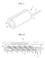
- the sheet pasting device 1 includes a sheet support section 2 that supports the sheet-shaped therapeutic substance A in a state in which the sheet-shaped therapeutic substance A is pasted to a surface, an extrusion member 3 (see Fig. 2 ) that is provided within the sheet support section 2 so as to be able to protrude from and retract into the surface of the sheet support section 2, and a drive mechanism (see Figs. 4 and 5 ) 4 that causes the extrusion member 3 to protrude from and retract into the surface.
- the sheet support section 2 is an elastically-deformable member that is formed in a hollow and substantially-rectangular plate-like shape in which a cavity portion 5 is provided, and that can be elastically deformed into a state in which the sheet support section 2 is rolled in a width direction as shown in Fig. 3 by an external force, and can be also deployed into a plate-like shape as shown in Fig. 1 by an elastic restoring force when the external force is released.
- a plurality of through holes 6 that open in a surface 2a of the sheet support section 2 and penetrate into the cavity portion 5 are provided in the surface 2a at intervals from each other.
- the extrusion member 3 is composed of a plurality of needle-shaped members (also referred to as needle-shaped members 3 below) that are respectively inserted into the through holes 6 of the sheet support section 2 so as to be movable in a longitudinal direction, and are arranged such that one ends can protrude from and retract into openings of the through holes 6 as shown in Fig. 4 .
- the sheet-shaped therapeutic substance A is pasted to the surface 2a of the sheet support section 2 and delivered in a state in which the needle-shaped members 3 are retracted into the openings of the through holes 6 of the sheet support section 2 as shown in Fig. 1 .
- the needle-shaped members 3 are moved within the through holes 6 to cause the one ends to protrude outside from the openings of the through holes 6 as shown in Fig. 2 . Respective portions of the sheet-shaped therapeutic substance A can be thereby pressed by the one ends of the respective needle-shaped members 3, and separated from the surface 2a of the sheet support section 2.
- the drive mechanism 4 includes an elastically-deformable base member 7 that is accommodated in the cavity portion 5 of the sheet support section 2 so as to be movable forward and backward, and a drive shaft 9 that is inserted into the cavity portion 5 from backward so as to be able to advance and retreat via a hollow shaft 8 coupled to a rear end of the sheet support section 2, and one end of which is coupled to the base member 7.
- each of the needle-shaped members 3 is coupled to the base member 7 within the cavity portion 5 so as to be swingable.
- the sheet-shaped therapeutic substance A is placed on the surface 2a with all the needle-shaped members 3 retracted into the through holes 6 of the sheet support section 2 by moving the drive shaft 9 backward with respect to the sheet support section 2 as shown in Figs. 1 to 4 .
- the sheet-shaped therapeutic substance A can be placed on the surface 2a of the sheet support section 2 in a bonded state by the viscosity of itself or the surface tension of a liquid such as pure water.
- the sheet-shaped therapeutic substance A and the sheet support section 2 are rolled in the width direction into a cylindrical shape as shown in Fig. 3 by the external force such that the therapeutic substance A is located on the inner side.
- the sheet-shaped therapeutic substance A is protected by the sheet support section 2.
- the maximum width dimension of a cross-sectional surface can be also made smaller. Therefore, the therapeutic substance A can be delivered to the diseased site B through a narrow channel such as a body cavity in an accommodated state in a cylindrical sheath (not shown). At this time, the therapeutic substance A can be protected so as not to come into contact with peripheral tissue.
- the sheet support section 2 When the sheet support section 2 is arranged in the vicinity of the diseased site B, the sheet support section 2 is exposed from the sheath, and the external force for holding the sheet support section 2 in a cylindrical shape is released. The sheet support section 2 and the sheet-shaped therapeutic substance A are thereby deployed into a flat form as shown in Fig. 1 by the elastic restoring force of the sheet support section 2.
- the sheet-shaped therapeutic substance A placed on the surface 2a of the sheet support section 2 is moved closer to the diseased site B so as to be opposed to the diseased site B.
- the drive shaft 9 is moved forward to advance the base member 7 coupled to the end portion of the drive shaft 9 with respect to the sheet support section 2 as shown in Figs. 2 to 5 . Accordingly, all the needle-shaped members 3 move longitudinally within the corresponding through holes 6, and protrude outside from the openings of the through holes 6. When the base member 7 is pressed to a position in Fig. 3 , all the needle-shaped members 3 become upright with respect to the base member 7.
- the needle-shaped members 3 are respectively arranged in the plurality of through holes 6 provided at intervals, and caused to protrude from the openings of the through holes 6 at the same time.
- the therapeutic substance A is pressed at a plurality of positions at the same time, and separated from the surface 2a of the sheet support section 2.
- the sheet-shaped therapeutic substance A is pressed and pasted to the opposed diseased site B.
- the sheet-shaped therapeutic substance A can be protected so as not to be damaged during delivery.
- the therapeutic substance A is pasted to the diseased site B, the therapeutic substance A is pressed up and separated from the surface 2a of the sheet support section 2 by the plurality of needle-shaped members 3 at the same time.
- the separating force is not reduced even after the therapeutic substance A starts to be separated from the surface 2a of the sheet support section 2.
- the sheet-shaped therapeutic substance A is pressed and separated by the distal ends of the needle-shaped members 3.
- the distal ends of the needle-shaped members 3 preferably have a shape difficult to be pierced into the sheet-shaped therapeutic substance A.
- the distal ends preferably have a flat surface, or a hemispherical surface.
- the needle-shaped members 3 may include, at each of the distal ends, a sharply pointed end portion 3a, and a step portion (stopper portion) 3b arranged on the proximal end side of the pointed end portion 3a and having a large diameter dimension as shown in Fig. 6A .
- the step portion 3b may be also formed in a flange shape as shown in Fig. 6B .
- the pointed end portions 3a are preferably arranged so as to protrude outside from the surface 2a of the sheet support section 2 in a state in which the needle-shaped members 3 are retracted deepest into the through holes 6.
- a force for holding the therapeutic substance A on the sheet support section 2 can be increased by piercing the pointed end portions 3a of the needle-shaped members 3 into the sheet-shaped therapeutic substance A pasted to the surface 2a of the sheet support section 2.
- the step portions 3b arranged on the proximal end side of the pointed end portions 3a and having a large diameter dimension can prevent the needle-shaped members 3 from being further pierced into the therapeutic substance A, and also surely transmit a force for pressing up the therapeutic substance A to the therapeutic substance A.
- the plurality of needle-shaped members 3 are employed as the extrusion member 3.
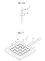
- a wire-shaped member 10 formed in a net-like shape may be also employed as shown in Fig. 7 .
- the wire-shaped member 10 is accommodated in a groove 11 formed in the surface 2a of the sheet support section 2.
- the wire-shaped member 10 is caused to protrude from the groove 11 as indicated by a chain line in Fig. 8 .
- the sheet-shaped therapeutic substance A placed on the surface 2a of the sheet support section 2 can be thereby separated from the surface 2a of the sheet support section 2.
- At least a portion of the sheet support section 2 is preferably formed of super-elastic alloy so as to obtain a sufficient elastic restoring force.
- the sheet pasting device 20 includes two rod-shaped members 21 that are arranged on the surface 2a of the sheet support section 2, and are provided movably along the surface 2a in a direction perpendicular to a longitudinal direction of the rod-shaped members 21, and a drive mechanism 22 that moves the rod-shaped members 21 as shown in Figs. 9 to 12 .
- the sheet support section 2 is also formed of an elastically-deformable material
- the rod-shaped members 21 are also formed of an elastically-deformable material
- a slit-like opening portion 23 that opens linearly in a direction perpendicular to the rod-shaped members 21 is formed in the surface of the sheet support section 2.
- Each of the rod-shaped members 21 has a length dimension extending over substantially the entire width of the sheet support section 2.
- the two rod-shaped members 21 can be moved between a state arranged adjacent to substantially a longitudinal center position of the sheet support section 2, and a state arranged apart from each other at both longitudinal end edges of the sheet support section 2 as shown in Fig. 9 .
- the drive mechanism 22 includes a wire 25 that is connected to a bracket 24 fixed to each of the rod-shaped members 21 and arranged in the cavity portion 5 of the sheet support section 2 via the opening portion 23, and a sheave 26 for holding the wire 25 as shown in Figs. 11 and 12 .
- the wire 25 is connected to one of the rod-shaped members 21 via the single sheave 26, and an intermediate position of the wire 25 is directly connected to the other of the rod-shaped members 21.
- the two rod-shaped members 21 can be moved at the same time from a state adjacent to each other as shown in Fig. 11 to a state apart from each other as shown in Fig. 12 .
- reference numeral 27 denotes an adhesive for bonding the sheet-shaped therapeutic substance A to the surface 2a of the sheet support section 2.
- the two rod-shaped members 21 are arranged adjacent to substantially the center of the sheet support section 2, and the sheet-shaped therapeutic substance A is bonded to the surface of the sheet support section 2 with the adhesive 27 as shown in Fig. 9 .
- the adhesive 27 include fibrin glue, gelatin-based adhesive, and sterilized water.
- the adhesive 27 may be applied over the entire surface of the sheet-shaped therapeutic substance A, or may be applied to positions existing at intervals as shown in Fig. 9 .
- the sheet support section 2 on which the sheet-shaped therapeutic substance A is placed as described above can be rolled in a cylindrical shape as shown in Fig. 3 , and easily delivered in a form with a small cross-sectional surface while protecting the therapeutic substance A in a similar manner to the first embodiment.
- the sheet support section 2 After being delivered to the vicinity of the diseased site B, the sheet support section 2 is deployed such that the sheet-shaped therapeutic substance A placed thereon is opposed to the diseased site B, and the wire 25 is pulled. Accordingly, the pulling force applied to the wire 25 is transmitted to the rod-shaped members 21 via the wire 25 and the sheave 26. The two rod-shaped members 21 are moved in a direction to separate from each other along the surface 2a of the sheet support section 2. As a result, the adhesive 27 for bonding the sheet-shaped therapeutic substance A to the sheet support section 2 is cut off by the rod-shaped members 21, and the adhesive force is eliminated.
- the sheet-shaped therapeutic substance A can be easily separated from the sheet support section 2 and pasted to the diseased site B.
- the two rod-shaped members 21 are moved at the same time toward the both ends from substantially the center of the sheet support section 2, so that a stretching force is applied to the sheet-shaped therapeutic substance A in a direction toward the end edges from the center at the same time.
- the therapeutic substance A can be advantageously pasted to the diseased site B in a sufficiently stretched state without winkling.
- the rod-shaped members 21 are also preferably formed of super-elastic alloy.
- a cylindrical external sheath 30 that accommodates the sheet support section 2 such that the sheet support section 2 can protrude from and retract into a distal-end opening 30a may be also provided.
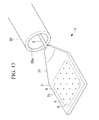
- an introduction portion 31 whose width dimension becomes gradually smaller toward the back is preferably provided on the rear end side of the sheet support section 2.
- the introduction portion 31 is curved such that the surface 2a of the sheet support section 2 is located on the inner side in its cross sectional shape.
- the width dimension of the introduction portion 31 on the backmost side is also formed smaller than the inner diameter dimension of the distal-end opening 30a of the external sheath 30.
- the width dimension of the sheet support section 2 is formed larger than the inner diameter dimension of the distal-end opening 30a of the external sheath 30. Accordingly, when the sheet support section 2 is pulled into the external sheath 30 from the backmost side of the introduction portion 31, both widthwise end edges of the introduction portion 31 come into contact with an inner edge of the distal-end opening 30a of the external sheath 30 at a lengthwise intermediate position of the introduction portion 31.
- the introduction portion 31 is curved such that the surface 2a on which the sheet-shaped therapeutic substance A is placed is located on the inner side, the introduction portion 31 is further curved so as to increase the curvature of the curve when the force toward the widthwise inner side is applied.
- the sheet support section 2 that is continuous to the introduction portion 31 is also curved in the same direction along with the curving of the introduction portion 31, formed into a cylindrical form as shown in Fig. 3 , and pulled into the external sheath 30 as shown in Fig. 14 .
- the sheet support section 2 is rolled in a cylindrical shape and accommodated in the external sheath 30.
- the sheet support section 2 can be thereby easily delivered out by assuming a compact form similar to that when the sheet-shaped therapeutic substance A is delivered in.
- rotation of the hollow shaft 8 and the sheet support section 2 fixed to a distal end of the hollow shaft 8 around the axis of the hollow shaft 8 may be restricted by providing a through hole 32 that penetrates through the hollow shaft 8 in the external sheath 30, and fitting together a key groove 32a provided in an inner surface of the through hole 32 and a key 8a provided on an outer surface of the hollow shaft 8 as shown in Fig. 14 .
- the sheet support section 2 and the external sheath 30 are maintained in a given phase, so that it is possible to confirm, on the proximal end side of the external sheath 30, which direction the sheet-shaped therapeutic substance A placed on the surface of the sheet support section 2 is directed.
- the through hole 32 provided in the external sheath 30 is preferably decentered to a position close to an outer surface with respect to the center of the external sheath 30.
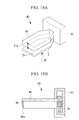
- a convex strip 33 that protrudes radially inward from an inner surface of a portion of the external sheath 30 in which the sheet support section 2 is accommodated may be also provided on the inner surface over a predetermined length of the longitudinal direction as shown in Fig. 15 .
- the convex strip 33 includes a guide surface 33a that smoothly rises from the inner surface of the external sheath 30 on at least one side of a circumferential direction. Accordingly, even when the width dimension of the sheet support section 2 is longer than the peripheral length of the inner surface of the external sheath 30, the sheet support section 2 can be rolled such that a widthwise end portion is directed radially inward by the guide surface 33a, and can be thereby accommodated in the external sheath 30 as shown in Fig. 15 .
- the guide surface 33a may be provided on the both sides of the circumferential direction of the convex strip 33 such that both ends of the sheet support section 2 are directed radially inward.
- the external sheath 30 accommodating the sheet support section 2, the hollow shaft 8, and the drive shaft 9 or the like may have rigidity or flexibility.
- the external sheath 30 or the like are formed of a material having flexibility, even when a channel where the external sheath 30 or the like are introduced (e.g., a channel of a soft outer tube member) is curved, the external sheath 30 or the like can be curved in accordance with the form.
- the therapeutic substance A is employed as an example of the sheet-shaped substance
- the diseased site B is employed as an example of a target site where the sheet-shaped substance A is to be pasted.
- the sheet-shaped therapeutic substance A include a hemostatic agent such as TachoComb (manufactured by CSL Behring), an adhesion barrier such as Seprafilm (manufactured by Kaken Pharmaceutical Co., Ltd.), other adhesives, and a bioabsorbable sheet absorbed in biological tissue.
- a pasting jig including: a cutting section that is provided adjacent to a surface of a sheet support section, and can cut a sheet-shaped substance into an area equal to or smaller than that of the surface between the pasting jig and the sheet support section, and a positioning section that performs positioning between the cutting section and the sheet support section.
- the pasting jig 40 includes a rectangular cutting section 41 having a smaller area than the surface of the sheet support section 2 (see Fig. 17 ), and a protrusion (positioning section) 42 that positions the cutting section 41 with respect to the sheet support section 2.
- a concave portion (positioning section) 43 to which the protrusion 42 is fitted is provided in the sheet support section 2.
- a surface where the protrusion 42 of the pasting jig 40 is provided is set at substantially the same height position as a cutting edge 41a of the cutting section 41.
- the concave portion 43 of the sheet support section 2 is arranged flush with the surface 2a on which the sheet-shaped substance A is placed. That is, when the protrusion 42 of the pasting jig 40 is fitted to the concave portion 43 of the sheet support section 2, the cutting section 41 is arranged at a position (a position indicated by a chain line C in Fig. 17 ) where the cutting edge 41a contacts the surface 2a of the sheet support section 2.
- a sheet-shaped substance larger than the sheet-shaped substance A to be pasted is arranged on the surface 2a of the sheet support section 2, and the sheet-shaped substance A is cut off by the cutting section 41 between the pasting jig 40 and the sheet support section 2 in a state in which the cutting section 41 and the sheet support section 2 are positioned by the protrusion 42 and the concave portion 43. Accordingly, the sheet-shaped substance A having an area equal to or smaller than the surface 2a of the sheet support section 2 can be pasted to the surface 2a of the sheet support section 2 in a positioned state. That is, cutting of the sheet-shaped substance A and pasting to the sheet support section 2 can be advantageously performed in one step.
- the pasting jig 40 includes a plate-like member 44 that covers the entire cutting section 41 as shown in Figs. 16 to 18 . Accordingly, the sheet-shaped substance A is arranged on the surface 2a of the sheet support section 2 with the surface 2a directed vertically upward, and the pasting jig 40 is moved closer from vertically above to cut the sheet-shaped substance A by the cutting section 41. In the cutting operation, the upper side of the sheet-shaped substance A is covered with the plate-like member 44. Consequently, dust or the like falling from above during the operation can be prevented from adhering to the sheet-shaped substance A.
- the cutting section 41 and the sheet support section 2 are positioned by fitting the protrusion 42 to the concave portion 43. It is also possible to employ the pasting jig 40 including a bracket 45 that is arranged in position on the sheet support section 2, the plate-like member 44 that is urged vertically upward with respect to the bracket 45 by a spring 46, and the cutting section 41 that is downwardly fixed to a lower portion of the plate-like member 44 as shown in Figs. 18A and 18B .
- the sheet-shaped substance A can be cut off by the downward cutting section 41, and pasted to the entire surface 2a of the sheet support section 2.
- the cutting section 41 has the same shape as the outer shape of the sheet support section 2, and the cutting section 41 is moved down along an outer edge of the sheet support section 2 outside the outer edge, so that the sheet-shaped substance A can be easily cut off by shearing.
- the pasting jig according to the item 1 or 2 including a pressing section that is made of an elastic material elastically deformable between a position protruding from a cutting edge of the cutting section and a position retracted from the cutting edge.
- the pasting jig according to the item 3 including a restricting member that is arranged at a position retracted from the cutting edge of the cutting section, and restricts further elastic deformation of the pressing section.
- the pasting jig 40 includes a pressing section 47 that is made of an elastic material such as rubber and sponge on the inner side of the rectangular cutting section 41 as shown in Fig. 16 .
- the pressing section 47 protrudes to the distal end side from the cutting section 41 as shown in Fig. 19 at a stage before the cutting section 41 comes into contact with the sheet-shaped substance A.
- the pressing section 47 can be elastically deformed to a position retracted to the proximal end side from the cutting section 41 as shown in Fig. 20 at a stage of cutting the sheet-shaped substance A.
- a restricting member 48 that is arranged at a position retracted from the cutting edge 41a of the cutting section 41, and comes into abutment against the sheet-shaped substance A at a point of time when the pressing section 47 is compressed, thereby restricting further compression of the pressing section 47 is provided at a position adjacent to the inner side of the cutting section 41.
- the pressing section 47 is in contact with the sheet-shaped substance A before the cutting section 41 cuts the sheet-shaped substance A, and keeps pressing the sheet-shaped substance A even during cutting.
- the cutting operation can be stably performed.
- the cutting section 41 itself serves as a restricting member, so that it is not necessary to separately provide the restricting member.
- the method for pasting the sheet-shaped substance A by using the above pasting jig 40 is as follows.
Landscapes
- Health & Medical Sciences (AREA)
- Life Sciences & Earth Sciences (AREA)
- Anesthesiology (AREA)
- Biomedical Technology (AREA)
- Heart & Thoracic Surgery (AREA)
- Hematology (AREA)
- Engineering & Computer Science (AREA)
- Animal Behavior & Ethology (AREA)
- General Health & Medical Sciences (AREA)
- Public Health (AREA)
- Veterinary Medicine (AREA)
- Media Introduction/Drainage Providing Device (AREA)
- Infusion, Injection, And Reservoir Apparatuses (AREA)
- Surgical Instruments (AREA)
Abstract
Description
- The present invention relates to a sheet pasting device.
- Conventionally, there has been known a delivery and administration instrument for therapeutic substances that delivers a sheet-shaped therapeutic substance into a body, and pastes the sheet-shaped therapeutic substance to a diseased site (e.g., see
Patent Literature 1.). - The instrument delivers the sheet-shaped therapeutic substance by placing the therapeutic substance on a flat sheet support section such that a plurality of opening portions provided in the sheet support section are closed by the sheet-shaped therapeutic substance, decreasing the pressure of a fluid fed to the opening portions, and thereby causing the therapeutic substance to adhere to the sheet support section. The instrument pastes the therapeutic substance to the diseased site by increasing the pressure of the fluid fed to the opening portions in the vicinity of the diseased site, and thereby separating the therapeutic substance from the sheet support section.
- {PTL 1}
Japanese Unexamined Patent Application, Publication No.2008-173333 - However, in the instrument in
Patent Literature 1, the therapeutic substance adheres to the sheet support section at a plurality of positions by the pressure of the fluid fed to the plurality of opening portions from a single pipe line. Therefore, if any of the opening portions is not closed by the therapeutic substance at the time of separation, the fluid leaks from the released one of the opening portions, thereby making it difficult to separate the entire therapeutic substance. - The present invention has been made in view of the aforementioned circumstances, and an object thereof is to provide a sheet pasting device which can separate a sheet-shaped substance surely over the entire surface with a simple configuration.
- To achieve the above object, the present invention provides the following solutions.
- One aspect of the present invention provides a sheet pasting device including: an elastically-deformable sheet support section that is provided with a flat surface, and supports a sheet-shaped substance in a state in which the sheet-shaped substance is pasted to the surface; an extrusion member that is provided so as to be able to protrude from and retract into the surface of the sheet support section; and a drive mechanism that causes the extrusion member to protrude from and retract into the surface.
- In accordance with the present invention, by pasting the sheet-shaped substance to the surface of the sheet support section, and curving the sheet support section such that the surface on the sheet-shaped substance side is located on the inner side, the sheet-shaped substance can be delivered while being protected. When the sheet-shaped substance is pasted to a target site, the sheet support section is deployed such that the sheet-shaped substance is opposed to the target site, and the drive mechanism is operated to cause the extrusion member to protrude from the surface of the sheet support section. Accordingly, the sheet-shaped substance pasted to the surface of the sheet support section can be pressed by the extrusion member, separated from the surface of the sheet support section, and pasted to the target site.
- In this case, in accordance with the present aspect, the separating force is not weakened even after the sheet-shaped substance starts to be separated from the surface of the sheet support section unlike in a conventional case in which the sheet-shaped substance is separated by the pressure of a fluid discharged from a plurality of opening portions. Thus, the sheet-shaped substance can be separated surely over the entire surface with a simple configuration.
- In the above aspect, the sheet support section may include a plurality of holes that open in the surface, and the extrusion member may be a plurality of needle-shaped members whose distal ends are caused to protrude from and retract into the surface at the same time through the two or more holes.
- Accordingly, when the drive mechanism is operated, the needle-shaped members are respectively caused to protrude from the plurality of holes opening in the surface of the sheet support section. The sheet-shaped substance can be thereby pressed by the needle-shaped members at the two or more positions, and separated from the sheet support section easily and more surely over the entire surface.
- In the above aspect, the needle-shaped members may include, at each of the distal ends, a pointed end portion pierced into the sheet-shaped substance, and a stopper portion arranged on a proximal end side of the pointed end portion and having a larger diameter dimension than the pointed end portion.
- Accordingly, when the sheet-shaped substance is supported on the sheet support section with the needle-shaped members slightly protruding from the surface of the sheet support section, the pointed end portions provided at the distal ends of the needle-shaped members are pierced into the sheet-shaped substance, so that the sheet-shaped substance can be supported so as not to fall off the sheet support section.
- In this case, by abutting against the stopper portions provided on the proximal end side of the pointed end portions, the sheet-shaped substance is held such that the needle-shaped members are not pierced any more. When the drive mechanism is operated, the sheet-shaped substance can be pressed by the stopper portions, separated from the sheet support section, and easily pasted to the target site.
- In the above aspect, the sheet support section may include a groove that opens in the surface, and the extrusion member may be a wire-shaped member that is accommodated in the groove, and caused to protrude from and retract into the surface.
- Accordingly, when the drive mechanism is operated, the wire-shaped member is caused to protrude from the groove opening in the surface of the sheet support section. The sheet-shaped substance can be thereby pressed by a line by the wire-shaped member, and separated from the sheet support section easily and more surely over the entire surface.
- In the above aspect, the wire-shaped member may be configured in a net-like shape.
- Accordingly, the sheet-shaped substance can be pressed at more positions by the net-like wire-shaped member. It is thereby possible to separate the sheet-shaped substance from the sheet-shaped member more surely over the entire surface while dispersing the pressing force applied to the sheet-shaped substance.
- Another aspect of the present invention is to provide a sheet pasting device including: an elastically-deformable sheet support section that is provided with a flat surface, and supports a sheet-shaped substance in a state in which the sheet-shaped substance is pasted to the surface with an adhesive; a rod-shaped member that is arranged along the surface of the sheet support section, and is provided movably along the surface in a direction crossing a longitudinal direction of the rod-shaped member; and a drive mechanism that moves the rod-shaped member along the surface.
- Accordingly, by pasting the sheet-shaped substance to the surface of the sheet support section with an adhesive, and curving the sheet support section such that the surface on the sheet-shaped substance side is located on the inner side, the sheet-shaped substance can be delivered while being protected. When the sheet-shaped substance is pasted to a target site, the sheet support section is deployed such that the sheet-shaped substance is opposed to the target site, and the drive mechanism is operated to move the rod-shaped member, which is arranged along the surface of the sheet support section, along the surface of the sheet support section in the direction crossing the longitudinal direction. Adhesion between the sheet-shaped substance and the sheet support section with the adhesive can be thereby cut off, so that the sheet-shaped substance can be separated from the surface of the sheet support section, and pasted to the target site.
- In the above aspect, the rod-shaped member may include two rod-shaped members, and the drive mechanism may move the two rod-shaped members between a position adjacent to substantially a center of the surface of the sheet support section, and a position apart from each other in the vicinity of an end edge of the surface.
- Accordingly, the sheet-shaped substance is bonded to the sheet support section with the adhesive in a state in which the rod-shaped members are arranged adjacent to substantially the center of the surface of the sheet support section. When the sheet-shaped substance is pasted to the target site, the two rod-shaped members are spaced apart from each other, and moved to the vicinity of end portions of the surface of the sheet support section. The adhesion over the entire surface of the sheet-shaped substance can be thereby cut off by the rod-shaped members. In this case, a force applied to the sheet-shaped substance from the rod-shaped members can be equally distributed in two directions. The sheet-shaped substance can be thereby prevented from wrinkling.
- In any of the above aspects, a cylindrical external sheath may be provided, the sheet support section may be provided so as to be able to protrude from and retract into a distal-end opening of the external sheath, and the sheet support section may include an introduction portion having a width dimension decreasing toward a proximal end side, and having a sectional shape curved such that the surface side is located on an inner side.
- Accordingly, the sheet support section where the sheet-shaped substance is pasted to the surface can be accommodated in the cylindrical external sheath and delivered in a state in which the sheet support section is rolled in a width direction, so that the sheet-shaped substance is protected so as not to come into contact with a peripheral object during delivery. When the sheet support section is caused to protrude from the distal-end opening of the external sheath after being delivered to the target site, the sheet support section is deployed by its elastic restoring force, thereby exposing the sheet-shaped substance pasted to the surface. Consequently, the sheet-shaped substance can be easily pasted to the target site.
- In this case, after the sheet-shaped substance is pasted, the sheet support section is moved in a direction into the external sheath. The introduction portion provided on the proximal end side of the sheet support section has a width dimension decreasing toward the proximal end side. Thus, when the introduction portion is pulled into the distal-end opening of the external sheath, widthwise end edges of the introduction portion come into contact with an inner edge of the distal-end opening of the external sheath on the way, and the introduction thereby receives an external force toward the widthwise inner side from the inner edge.
- Since the introduction portion has a sectional shape curved such that the surface side is located on the inner side, the external force acts as a force for curving the sheet support section such that the surface is located on the inner side. Thus, the sheet member can be rolled in the width direction and easily accommodated in the external sheath. Accordingly, when the sheet support section is moved after pasting the sheet-shaped substance, the sheet support section can be also moved in a rolled compact state without interfering with the periphery.
- In any of the above aspects, a convex strip that protrudes radially inward over a predetermined length of a longitudinal direction from an inner surface of a portion of the external sheath where the sheet support section is accommodated may be provided on the inner surface, and the convex strip may include, on at least one side of a circumferential direction, a guide surface that smoothly rises from the inner surface of the external sheath, and directs a widthwise end portion of the accommodated sheet support section radially inward.
- Accordingly, when the sheet support section is accommodated in the external sheath while being rolled in the width direction, a portion of the sheet support section climbs onto the convex strip, so that the widthwise end portion is directed radially inward away from the inner peripheral surface of the external sheath. As a result, even when the width dimension of the sheet support section is larger than the inner peripheral length of the external sheath, the sheet support section can be accommodated in the external sheath by partially overlapping the widthwise end portions.
- The present invention provides an effect that the sheet-shaped substance can be separated surely over the entire surface with a simple configuration.
-
- {
Fig. 1 }
Fig. 1 is a perspective view illustrating a sheet pasting device according to a first embodiment of the present invention. - {
Fig. 2 }
Fig. 2 is a perspective view illustrating a state in which needle-shaped members protrude from openings in a surface of the sheet pasting device inFig. 1 . - {
Fig. 3 }
Fig. 3 is a perspective view for explaining the form of a sheet support section when a sheet-shaped substance is delivered by the sheet pasting device inFig. 1 . - {
Fig. 4 }
Fig. 4 is a longitudinal sectional view illustrating a state in which the sheet-shaped substance is located close to a target side by the sheet pasting device inFig. 1 . - {
Fig. 5 }
Fig. 5 is a perspective view illustrating a state in which the needle-shaped members protrude from the openings in the surface of the sheet pasting device inFig. 1 so as to paste the sheet-shaped substance to the target site. - {
Fig. 6A }
Fig. 6A is an enlarged view illustrating a member including a step portion as a modification of the needle-shaped member of the sheet pasting device inFig. 1 . - {
Fig. 6B }
Fig. 6B is an enlarged view illustrating a member including a flange-shaped step portion as a modification of the needle-shaped member of the sheet pasting device inFig. 1 . - {
Fig. 7 }
Fig. 7 is a perspective view illustrating a device including an extrusion member composed of a wire member as a modification of the sheet pasting device inFig. 1 . - {
Fig. 8 }
Fig. 8 is a view for explaining the operation of the extrusion member inFig. 7 . - {
Fig. 9 }
Fig. 9 is a perspective view illustrating a sheet pasting device according to a second embodiment of the present invention. - {
Fig. 10 }
Fig. 10 is a perspective view illustrating a state in which an adhesive force by an adhesive is eliminated by rod-shaped members of the sheet pasting device inFig. 9 . - {
Fig. 11 }
Fig. 11 is a longitudinal sectional view illustrating the sheet pasting device inFig. 9 . - {
Fig. 12 }
Fig. 12 is a longitudinal sectional view illustrating the sheet pasting device inFig. 10 . - {
Fig. 13 }
Fig. 13 is a perspective view illustrating a device including an introduction portion at a rear end as a modification of the sheet pasting device inFig. 1 . - {
Fig. 14 }
Fig. 14 is a longitudinal sectional view of the sheet pasting device inFig. 13 . - {
Fig. 15 }
Fig. 15 is a cross sectional view illustrating another modification of the sheet pasting device inFig. 1 . - {
Fig. 16 }
Fig. 16 is a perspective view illustrating a pasting device for pasting a sheet-shaped substance to a sheet pasting device. - {
Fig. 17 }
Fig. 17 is a perspective view illustrating a sheet pasting device to which the pasting device inFig. 16 can be attached in a positioned state. - {
Fig. 18A }
Fig. 18A is a perspective view illustrating a modification of the pasting device inFig. 16 . - {
Fig. 18B }
Fig. 18B is a longitudinal sectional view illustrating the modification of the pasting device inFig. 16 . - {
Fig. 19 }
Fig. 19 is a view illustrating a state before the sheet-shaped substance is cut off as a modification of the pasting device inFig. 16 . - {
Fig. 20 }
Fig. 20 is a view illustrating a state after the sheet-shaped substance is cut off by the pasting device inFig. 19 . - {
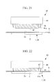
Fig. 21 }
Fig. 21 is a view illustrating a state before the sheet-shaped substance is cut off as another modification of the pasting device inFig. 16 . - {
Fig. 22 }
Fig. 22 is a view illustrating a state after the sheet-shaped substance is cut off by the pasting device inFig. 21 . - A
sheet pasting device 1 according to a first embodiment of the present invention is described below by reference to the drawings. - For example, the
sheet pasting device 1 according to the present embodiment is a device that delivers a sheet-shaped therapeutic substance A to the vicinity of a diseased site, and pastes the sheet-shaped therapeutic substance A to the diseased site. - As shown in
Figs. 1 to 5 , thesheet pasting device 1 includes asheet support section 2 that supports the sheet-shaped therapeutic substance A in a state in which the sheet-shaped therapeutic substance A is pasted to a surface, an extrusion member 3 (seeFig. 2 ) that is provided within thesheet support section 2 so as to be able to protrude from and retract into the surface of thesheet support section 2, and a drive mechanism (seeFigs. 4 and5 ) 4 that causes theextrusion member 3 to protrude from and retract into the surface. - The
sheet support section 2 is an elastically-deformable member that is formed in a hollow and substantially-rectangular plate-like shape in which acavity portion 5 is provided, and that can be elastically deformed into a state in which thesheet support section 2 is rolled in a width direction as shown inFig. 3 by an external force, and can be also deployed into a plate-like shape as shown inFig. 1 by an elastic restoring force when the external force is released. - A plurality of through
holes 6 that open in asurface 2a of thesheet support section 2 and penetrate into thecavity portion 5 are provided in thesurface 2a at intervals from each other. - The
extrusion member 3 is composed of a plurality of needle-shaped members (also referred to as needle-shapedmembers 3 below) that are respectively inserted into the throughholes 6 of thesheet support section 2 so as to be movable in a longitudinal direction, and are arranged such that one ends can protrude from and retract into openings of the throughholes 6 as shown inFig. 4 . The sheet-shaped therapeutic substance A is pasted to thesurface 2a of thesheet support section 2 and delivered in a state in which the needle-shapedmembers 3 are retracted into the openings of the throughholes 6 of thesheet support section 2 as shown inFig. 1 . The needle-shapedmembers 3 are moved within the throughholes 6 to cause the one ends to protrude outside from the openings of the throughholes 6 as shown inFig. 2 . Respective portions of the sheet-shaped therapeutic substance A can be thereby pressed by the one ends of the respective needle-shapedmembers 3, and separated from thesurface 2a of thesheet support section 2. - As shown in
Fig. 4 , thedrive mechanism 4 includes an elastically-deformable base member 7 that is accommodated in thecavity portion 5 of thesheet support section 2 so as to be movable forward and backward, and adrive shaft 9 that is inserted into thecavity portion 5 from backward so as to be able to advance and retreat via ahollow shaft 8 coupled to a rear end of thesheet support section 2, and one end of which is coupled to thebase member 7. - The other end of each of the needle-shaped
members 3 is coupled to thebase member 7 within thecavity portion 5 so as to be swingable. - Accordingly, as shown in
Fig. 4 , when thebase member 7 is moved backward within thecavity portion 5, all the needle-shapedmembers 3 are laid down along thebase member 7 such that the one ends are arranged inside the throughholes 6 so as not to protrude from the openings of the through holes 6. On the other hand, as shown inFig. 5 , when thebase member 7 is moved forward within thecavity portion 5, all the needle-shapedmembers 3 become upright with respect to thebase member 7 such that the one ends protrude outside from the openings of the through holes 6. - A case in which the sheet-shaped therapeutic substance A is pasted to a diseased site B by using the
sheet pasting device 1 according to the present embodiment having the above configuration is described. - To paste the sheet-shaped therapeutic substance A to the diseased site B by using the
sheet pasting device 1 according to the present embodiment, first, the sheet-shaped therapeutic substance A is placed on thesurface 2a with all the needle-shapedmembers 3 retracted into the throughholes 6 of thesheet support section 2 by moving thedrive shaft 9 backward with respect to thesheet support section 2 as shown inFigs. 1 to 4 . - In this case, the sheet-shaped therapeutic substance A can be placed on the
surface 2a of thesheet support section 2 in a bonded state by the viscosity of itself or the surface tension of a liquid such as pure water. - In this state, the sheet-shaped therapeutic substance A and the
sheet support section 2 are rolled in the width direction into a cylindrical shape as shown inFig. 3 by the external force such that the therapeutic substance A is located on the inner side. - Accordingly, the sheet-shaped therapeutic substance A is protected by the
sheet support section 2. The maximum width dimension of a cross-sectional surface can be also made smaller. Therefore, the therapeutic substance A can be delivered to the diseased site B through a narrow channel such as a body cavity in an accommodated state in a cylindrical sheath (not shown). At this time, the therapeutic substance A can be protected so as not to come into contact with peripheral tissue. - When the
sheet support section 2 is arranged in the vicinity of the diseased site B, thesheet support section 2 is exposed from the sheath, and the external force for holding thesheet support section 2 in a cylindrical shape is released. Thesheet support section 2 and the sheet-shaped therapeutic substance A are thereby deployed into a flat form as shown inFig. 1 by the elastic restoring force of thesheet support section 2. - In this state, the sheet-shaped therapeutic substance A placed on the
surface 2a of thesheet support section 2 is moved closer to the diseased site B so as to be opposed to the diseased site B. - The
drive shaft 9 is moved forward to advance thebase member 7 coupled to the end portion of thedrive shaft 9 with respect to thesheet support section 2 as shown inFigs. 2 to 5 . Accordingly, all the needle-shapedmembers 3 move longitudinally within the corresponding throughholes 6, and protrude outside from the openings of the through holes 6. When thebase member 7 is pressed to a position inFig. 3 , all the needle-shapedmembers 3 become upright with respect to thebase member 7. - The needle-shaped
members 3 protruding from the openings of the throughholes 6 press the sheet-shaped therapeutic substance A pasted to thesurface 2a of thesheet support section 2 by their distal ends. The needle-shapedmembers 3 are respectively arranged in the plurality of throughholes 6 provided at intervals, and caused to protrude from the openings of the throughholes 6 at the same time. Thus, the therapeutic substance A is pressed at a plurality of positions at the same time, and separated from thesurface 2a of thesheet support section 2. The sheet-shaped therapeutic substance A is pressed and pasted to the opposed diseased site B. - That is, in accordance with the
sheet pasting device 1 according to the present embodiment, since thesheet support section 2 is delivered in a curved state, the sheet-shaped therapeutic substance A can be protected so as not to be damaged during delivery. When the therapeutic substance A is pasted to the diseased site B, the therapeutic substance A is pressed up and separated from thesurface 2a of thesheet support section 2 by the plurality of needle-shapedmembers 3 at the same time. Thus, as compared with a conventional case in which the therapeutic substance is separated by the pressure of a fluid, the separating force is not reduced even after the therapeutic substance A starts to be separated from thesurface 2a of thesheet support section 2. Thus, there is an advantage that the therapeutic substance A can be more surely separated and pasted to the diseased site B. - In the present embodiment, the sheet-shaped therapeutic substance A is pressed and separated by the distal ends of the needle-shaped
members 3. In this case, the distal ends of the needle-shapedmembers 3 preferably have a shape difficult to be pierced into the sheet-shaped therapeutic substance A. For example, the distal ends preferably have a flat surface, or a hemispherical surface. - Instead, the needle-shaped
members 3 may include, at each of the distal ends, a sharplypointed end portion 3a, and a step portion (stopper portion) 3b arranged on the proximal end side of thepointed end portion 3a and having a large diameter dimension as shown inFig. 6A . Thestep portion 3b may be also formed in a flange shape as shown inFig. 6B . In this case, thepointed end portions 3a are preferably arranged so as to protrude outside from thesurface 2a of thesheet support section 2 in a state in which the needle-shapedmembers 3 are retracted deepest into the through holes 6. - Accordingly, a force for holding the therapeutic substance A on the
sheet support section 2 can be increased by piercing thepointed end portions 3a of the needle-shapedmembers 3 into the sheet-shaped therapeutic substance A pasted to thesurface 2a of thesheet support section 2. When the therapeutic substance A is pasted to the diseased site B, thestep portions 3b arranged on the proximal end side of thepointed end portions 3a and having a large diameter dimension can prevent the needle-shapedmembers 3 from being further pierced into the therapeutic substance A, and also surely transmit a force for pressing up the therapeutic substance A to the therapeutic substance A. - In the present embodiment, the plurality of needle-shaped
members 3 are employed as theextrusion member 3. Instead, a wire-shapedmember 10 formed in a net-like shape may be also employed as shown inFig. 7 . In the example shown inFig. 7 , the wire-shapedmember 10 is accommodated in agroove 11 formed in thesurface 2a of thesheet support section 2. By transmitting a rotating force to apulley 12 attached to one end edge of the wire-shapedmember 10 via abelt 13 as shown inFig. 8 , the wire-shapedmember 10 is caused to protrude from thegroove 11 as indicated by a chain line inFig. 8 . The sheet-shaped therapeutic substance A placed on thesurface 2a of thesheet support section 2 can be thereby separated from thesurface 2a of thesheet support section 2. - At least a portion of the
sheet support section 2 is preferably formed of super-elastic alloy so as to obtain a sufficient elastic restoring force. - Next, a
sheet pasting device 20 according to a second embodiment of the present invention is described below by reference to the drawings. - In the description of the present embodiment, components common to those of the
sheet pasting device 1 according to the first embodiment are assigned the same reference numerals, and the description thereof is omitted. - The
sheet pasting device 20 according to the present embodiment includes two rod-shapedmembers 21 that are arranged on thesurface 2a of thesheet support section 2, and are provided movably along thesurface 2a in a direction perpendicular to a longitudinal direction of the rod-shapedmembers 21, and adrive mechanism 22 that moves the rod-shapedmembers 21 as shown inFigs. 9 to 12 . - In the present embodiment, the
sheet support section 2 is also formed of an elastically-deformable material, and the rod-shapedmembers 21 are also formed of an elastically-deformable material. - A slit-
like opening portion 23 that opens linearly in a direction perpendicular to the rod-shapedmembers 21 is formed in the surface of thesheet support section 2. - Each of the rod-shaped
members 21 has a length dimension extending over substantially the entire width of thesheet support section 2. The two rod-shapedmembers 21 can be moved between a state arranged adjacent to substantially a longitudinal center position of thesheet support section 2, and a state arranged apart from each other at both longitudinal end edges of thesheet support section 2 as shown inFig. 9 . - The
drive mechanism 22 includes awire 25 that is connected to abracket 24 fixed to each of the rod-shapedmembers 21 and arranged in thecavity portion 5 of thesheet support section 2 via the openingportion 23, and asheave 26 for holding thewire 25 as shown inFigs. 11 and 12 . Thewire 25 is connected to one of the rod-shapedmembers 21 via thesingle sheave 26, and an intermediate position of thewire 25 is directly connected to the other of the rod-shapedmembers 21. - Accordingly, only by pulling the
single wire 25 in a direction of an arrow, the two rod-shapedmembers 21 can be moved at the same time from a state adjacent to each other as shown inFig. 11 to a state apart from each other as shown inFig. 12 . - In
Fig. 9 ,reference numeral 27 denotes an adhesive for bonding the sheet-shaped therapeutic substance A to thesurface 2a of thesheet support section 2. - To paste the sheet-shaped therapeutic substance A to the diseased site B by using the
sheet pasting device 20 according to the present embodiment having the above configuration, first, the two rod-shapedmembers 21 are arranged adjacent to substantially the center of thesheet support section 2, and the sheet-shaped therapeutic substance A is bonded to the surface of thesheet support section 2 with the adhesive 27 as shown inFig. 9 . Examples of the adhesive 27 include fibrin glue, gelatin-based adhesive, and sterilized water. - The adhesive 27 may be applied over the entire surface of the sheet-shaped therapeutic substance A, or may be applied to positions existing at intervals as shown in
Fig. 9 . - The
sheet support section 2 on which the sheet-shaped therapeutic substance A is placed as described above can be rolled in a cylindrical shape as shown inFig. 3 , and easily delivered in a form with a small cross-sectional surface while protecting the therapeutic substance A in a similar manner to the first embodiment. - After being delivered to the vicinity of the diseased site B, the
sheet support section 2 is deployed such that the sheet-shaped therapeutic substance A placed thereon is opposed to the diseased site B, and thewire 25 is pulled. Accordingly, the pulling force applied to thewire 25 is transmitted to the rod-shapedmembers 21 via thewire 25 and thesheave 26. The two rod-shapedmembers 21 are moved in a direction to separate from each other along thesurface 2a of thesheet support section 2. As a result, the adhesive 27 for bonding the sheet-shaped therapeutic substance A to thesheet support section 2 is cut off by the rod-shapedmembers 21, and the adhesive force is eliminated. - Therefore, by pressing the sheet-shaped therapeutic substance A against the diseased site B in this state, the sheet-shaped therapeutic substance A can be easily separated from the
sheet support section 2 and pasted to the diseased site B. - In accordance with the
sheet pasting device 20 according to the present embodiment, the two rod-shapedmembers 21 are moved at the same time toward the both ends from substantially the center of thesheet support section 2, so that a stretching force is applied to the sheet-shaped therapeutic substance A in a direction toward the end edges from the center at the same time. As a result, the therapeutic substance A can be advantageously pasted to the diseased site B in a sufficiently stretched state without winkling. - In the present embodiment, the rod-shaped
members 21 are also preferably formed of super-elastic alloy. - In the
sheet pasting devices external sheath 30 that accommodates thesheet support section 2 such that thesheet support section 2 can protrude from and retract into a distal-end opening 30a may be also provided. As shownFig. 13 , anintroduction portion 31 whose width dimension becomes gradually smaller toward the back is preferably provided on the rear end side of thesheet support section 2. Theintroduction portion 31 is curved such that thesurface 2a of thesheet support section 2 is located on the inner side in its cross sectional shape. - The width dimension of the
introduction portion 31 on the backmost side is also formed smaller than the inner diameter dimension of the distal-end opening 30a of theexternal sheath 30. - Moreover, the width dimension of the
sheet support section 2 is formed larger than the inner diameter dimension of the distal-end opening 30a of theexternal sheath 30. Accordingly, when thesheet support section 2 is pulled into theexternal sheath 30 from the backmost side of theintroduction portion 31, both widthwise end edges of theintroduction portion 31 come into contact with an inner edge of the distal-end opening 30a of theexternal sheath 30 at a lengthwise intermediate position of theintroduction portion 31. - When the
sheet support section 2 is further pulled into theexternal sheath 30 from this state, a force toward the widthwise inner side is applied to theintroduction portion 31 from the inner edge of the distal-end opening 30a of theexternal sheath 30. Since theintroduction portion 31 is curved such that thesurface 2a on which the sheet-shaped therapeutic substance A is placed is located on the inner side, theintroduction portion 31 is further curved so as to increase the curvature of the curve when the force toward the widthwise inner side is applied. - As a result, the
sheet support section 2 that is continuous to theintroduction portion 31 is also curved in the same direction along with the curving of theintroduction portion 31, formed into a cylindrical form as shown inFig. 3 , and pulled into theexternal sheath 30 as shown inFig. 14 . - That is, after the sheet-shaped therapeutic substance A is pasted to the diseased site B, the
sheet support section 2 is rolled in a cylindrical shape and accommodated in theexternal sheath 30. Thesheet support section 2 can be thereby easily delivered out by assuming a compact form similar to that when the sheet-shaped therapeutic substance A is delivered in. - In the present embodiment, rotation of the
hollow shaft 8 and thesheet support section 2 fixed to a distal end of thehollow shaft 8 around the axis of thehollow shaft 8 may be restricted by providing a throughhole 32 that penetrates through thehollow shaft 8 in theexternal sheath 30, and fitting together akey groove 32a provided in an inner surface of the throughhole 32 and a key 8a provided on an outer surface of thehollow shaft 8 as shown inFig. 14 . Accordingly, thesheet support section 2 and theexternal sheath 30 are maintained in a given phase, so that it is possible to confirm, on the proximal end side of theexternal sheath 30, which direction the sheet-shaped therapeutic substance A placed on the surface of thesheet support section 2 is directed. - In this case, the through
hole 32 provided in theexternal sheath 30 is preferably decentered to a position close to an outer surface with respect to the center of theexternal sheath 30. When thesheet support section 2 is rolled in a cylindrical shape as shown inFig. 3 , the position of thehollow shaft 8 is decentered from the center of the cylindricalsheet support section 2. Thus, by previously decentering the throughhole 32, thesheet support section 2 rolled in the cylindrical shape can be easily accommodated in theexternal sheath 30. - A
convex strip 33 that protrudes radially inward from an inner surface of a portion of theexternal sheath 30 in which thesheet support section 2 is accommodated may be also provided on the inner surface over a predetermined length of the longitudinal direction as shown inFig. 15 . Theconvex strip 33 includes aguide surface 33a that smoothly rises from the inner surface of theexternal sheath 30 on at least one side of a circumferential direction. Accordingly, even when the width dimension of thesheet support section 2 is longer than the peripheral length of the inner surface of theexternal sheath 30, thesheet support section 2 can be rolled such that a widthwise end portion is directed radially inward by theguide surface 33a, and can be thereby accommodated in theexternal sheath 30 as shown inFig. 15 . Theguide surface 33a may be provided on the both sides of the circumferential direction of theconvex strip 33 such that both ends of thesheet support section 2 are directed radially inward. - Also, in the above respective embodiments, the
external sheath 30 accommodating thesheet support section 2, thehollow shaft 8, and thedrive shaft 9 or the like may have rigidity or flexibility. In a case in which theexternal sheath 30 or the like are formed of a material having flexibility, even when a channel where theexternal sheath 30 or the like are introduced (e.g., a channel of a soft outer tube member) is curved, theexternal sheath 30 or the like can be curved in accordance with the form. - In the above embodiments, the therapeutic substance A is employed as an example of the sheet-shaped substance, and the diseased site B is employed as an example of a target site where the sheet-shaped substance A is to be pasted. Examples of the sheet-shaped therapeutic substance A include a hemostatic agent such as TachoComb (manufactured by CSL Behring), an adhesion barrier such as Seprafilm (manufactured by Kaken Pharmaceutical Co., Ltd.), other adhesives, and a bioabsorbable sheet absorbed in biological tissue.
- Next, a
pasting jig 40 and a method for pasting the sheet-shaped substance to thesheet support section 2 of the aforementionedsheet pasting devices - Conventionally, there has been a problem that it is necessary for a doctor to cut the therapeutic substance A with scissors and set the cut therapeutic substance A every time the sheet-shaped therapeutic substance A is pasted to the
sheet support section 2 of thesheet pasting devices - A pasting jig including: a cutting section that is provided adjacent to a surface of a sheet support section, and can cut a sheet-shaped substance into an area equal to or smaller than that of the surface between the pasting jig and the sheet support section, and a positioning section that performs positioning between the cutting section and the sheet support section.
- As shown in
Fig. 16 , thepasting jig 40 includes arectangular cutting section 41 having a smaller area than the surface of the sheet support section 2 (seeFig. 17 ), and a protrusion (positioning section) 42 that positions thecutting section 41 with respect to thesheet support section 2. On the other hand, as shown inFig. 17 , a concave portion (positioning section) 43 to which theprotrusion 42 is fitted is provided in thesheet support section 2. - A surface where the
protrusion 42 of thepasting jig 40 is provided is set at substantially the same height position as acutting edge 41a of thecutting section 41. Theconcave portion 43 of thesheet support section 2 is arranged flush with thesurface 2a on which the sheet-shaped substance A is placed. That is, when theprotrusion 42 of thepasting jig 40 is fitted to theconcave portion 43 of thesheet support section 2, the cuttingsection 41 is arranged at a position (a position indicated by a chain line C inFig. 17 ) where thecutting edge 41a contacts thesurface 2a of thesheet support section 2. - In accordance with the
pasting jig 40, a sheet-shaped substance larger than the sheet-shaped substance A to be pasted is arranged on thesurface 2a of thesheet support section 2, and the sheet-shaped substance A is cut off by the cuttingsection 41 between thepasting jig 40 and thesheet support section 2 in a state in which thecutting section 41 and thesheet support section 2 are positioned by theprotrusion 42 and theconcave portion 43. Accordingly, the sheet-shaped substance A having an area equal to or smaller than thesurface 2a of thesheet support section 2 can be pasted to thesurface 2a of thesheet support section 2 in a positioned state. That is, cutting of the sheet-shaped substance A and pasting to thesheet support section 2 can be advantageously performed in one step. - The pasting jig according to the
item 1, wherein the cutting section is fixed to a plate-like member that can cover the entire surface of the sheet support section. - The
pasting jig 40 includes a plate-like member 44 that covers theentire cutting section 41 as shown inFigs. 16 to 18 . Accordingly, the sheet-shaped substance A is arranged on thesurface 2a of thesheet support section 2 with thesurface 2a directed vertically upward, and thepasting jig 40 is moved closer from vertically above to cut the sheet-shaped substance A by the cuttingsection 41. In the cutting operation, the upper side of the sheet-shaped substance A is covered with the plate-like member 44. Consequently, dust or the like falling from above during the operation can be prevented from adhering to the sheet-shaped substance A. - In the example shown in
Figs. 16 and 17 , the cuttingsection 41 and thesheet support section 2 are positioned by fitting theprotrusion 42 to theconcave portion 43. It is also possible to employ thepasting jig 40 including abracket 45 that is arranged in position on thesheet support section 2, the plate-like member 44 that is urged vertically upward with respect to thebracket 45 by aspring 46, and thecutting section 41 that is downwardly fixed to a lower portion of the plate-like member 44 as shown inFigs. 18A and 18B . - Accordingly, by positioning the
sheet support section 2 in a lower portion of thebracket 45, and moving down the plate-like member 44 against the urging force of thespring 46 in a state in which the sheet-shaped substance A larger than thesurface 2a of thesheet support section 2 is arranged on thesurface 2a, the sheet-shaped substance A can be cut off by thedownward cutting section 41, and pasted to theentire surface 2a of thesheet support section 2. - In the example shown in
Figs. 18 and 18B , the cuttingsection 41 has the same shape as the outer shape of thesheet support section 2, and thecutting section 41 is moved down along an outer edge of thesheet support section 2 outside the outer edge, so that the sheet-shaped substance A can be easily cut off by shearing. - The pasting jig according to the
item - The pasting jig according to the
item 3, including a restricting member that is arranged at a position retracted from the cutting edge of the cutting section, and restricts further elastic deformation of the pressing section. - As shown in
Figs. 19 and 20 , thepasting jig 40 includes apressing section 47 that is made of an elastic material such as rubber and sponge on the inner side of therectangular cutting section 41 as shown inFig. 16 . Thepressing section 47 protrudes to the distal end side from the cuttingsection 41 as shown inFig. 19 at a stage before thecutting section 41 comes into contact with the sheet-shaped substance A. Thepressing section 47 can be elastically deformed to a position retracted to the proximal end side from the cuttingsection 41 as shown inFig. 20 at a stage of cutting the sheet-shaped substance A. - Also, a restricting
member 48 that is arranged at a position retracted from thecutting edge 41a of thecutting section 41, and comes into abutment against the sheet-shaped substance A at a point of time when thepressing section 47 is compressed, thereby restricting further compression of thepressing section 47 is provided at a position adjacent to the inner side of thecutting section 41. - Accordingly, the
pressing section 47 is in contact with the sheet-shaped substance A before thecutting section 41 cuts the sheet-shaped substance A, and keeps pressing the sheet-shaped substance A even during cutting. Thus, there is an advantage that the cutting operation can be stably performed. - By providing the restricting
member 48, pressing of the sheet-shaped substance A with an excessive force by thepressing section 47 is suppressed. Even when the sheet-shaped substance A is soft, the soundness can be maintained. - When the sheet-shaped substance A is cut off by bringing the
cutting edge 41a of thecutting section 41 into abutment against thesurface 2a of thesheet support section 2 as shown inFigs. 21 and 22 , the cuttingsection 41 itself serves as a restricting member, so that it is not necessary to separately provide the restricting member. - The method for pasting the sheet-shaped substance A by using the
above pasting jig 40 is as follows. - A method for pasting a sheet-shaped substance by using the pasting jig according to any of the
items 1 to 4, including: - an arranging step of arranging the sheet-shaped substance on the surface of the sheet support section;
- a positioning step of positioning the sheet support section and the pasting jig; and
- a cutting step of cutting the sheet-shaped substance by the cutting section of the pasting jig.
- The method for pasting a sheet-shaped substance according to the
item 5, wherein the cutting step is performed while covering the upper side of the sheet-shaped substance arranged on the surface of the sheet support section. - The method for pasting a sheet-shaped substance according to the
item -
- A
- Therapeutic substance (substance)
- 1, 20
- Sheet pasting device
- 2a
- Surface
- 2
- Sheet support section
- 3
- Needle-shaped member (extrusion member)
- 3a
- Pointed end portion
- 3b
- Step portion (stopper portion)
- 4
- Drive mechanism
- 6
- Through hole (hole)
- 10
- Wire-shaped member (extrusion member)
- 11
- Groove
- 12
- Pulley (drive mechanism)
- 13
- Belt (drive mechanism)
- 21
- Rod-shaped member
- 22
- Drive mechanism
- 27
- Adhesive
- 30
- External sheath
- 30a
- Distal-end opening
- 31
- Introduction portion
- 33
- Convex strip
- 33a
- Guide surface
Claims (9)
- A sheet pasting device comprising:an elastically-deformable sheet support section that is provided with a flat surface, and supports a sheet-shaped substance in a state in which the sheet-shaped substance is pasted to the surface;an extrusion member that is provided so as to be able to protrude from and retract into the surface of the sheet support section; anda drive mechanism that causes the extrusion member to protrude from and retract into the surface.
- The sheet pasting device according to claim 1,
wherein the sheet support section includes a plurality of holes that open in the surface, and
the extrusion member is a plurality of needle-shaped members whose distal ends are caused to protrude from and retract into the surface at the same time through the two or more holes. - The sheet pasting device according to claim 2,
wherein the needle-shaped members include, at each of the distal ends, a pointed end portion pierced into the sheet-shaped substance, and a stopper portion arranged on a proximal end side of the pointed end portion and having a larger diameter dimension than the pointed end portion. - The sheet pasting device according to claim 1,
wherein the sheet support section includes a groove that opens in the surface, and
the extrusion member is a wire-shaped member that is accommodated in the groove, and caused to protrude from and retract into the surface. - The sheet pasting device according to claim 4,
wherein the wire-shaped member is configured in a net-like shape. - A sheet pasting device comprising:an elastically-deformable sheet support section that is provided with a flat surface, and supports a sheet-shaped substance in a state in which the sheet-shaped substance is pasted to the surface with an adhesive;a rod-shaped member that is arranged along the surface of the sheet support section, and is provided movably along the surface in a direction crossing a longitudinal direction of the rod-shaped member; anda drive mechanism that moves the rod-shaped member along the surface.
- The sheet pasting device according to claim 6,
wherein the rod-shaped member includes two rod-shaped members, and
the drive mechanism moves the two rod-shaped members between a position adjacent to substantially a center of the surface of the sheet support section, and a position apart from each other in the vicinity of an end edge of the surface. - The sheet pasting device according to any of claims 1 to 7,
wherein a cylindrical external sheath is provided,
the sheet support section is provided so as to be able to protrude from and retract into a distal-end opening of the external sheath, and
the sheet support section includes an introduction portion having a width dimension decreasing toward a proximal end side, and having a sectional shape curved such that the surface side is located on an inner side. - The sheet pasting device according to claim 8,
wherein a convex strip that protrudes radially inward over a predetermined length of a longitudinal direction from an inner surface of a portion of the external sheath where the sheet support section is accommodated is provided on the inner surface, and
the convex strip includes, on at least one side of a circumferential direction, a guide surface that smoothly rises from the inner surface of the external sheath, and directs a widthwise end portion of the accommodated sheet support section radially inward.
Applications Claiming Priority (2)
| Application Number | Priority Date | Filing Date | Title |
|---|---|---|---|
| JP2012190434A JP5988778B2 (en) | 2012-08-30 | 2012-08-30 | Sheet pasting device |
| PCT/JP2013/073063 WO2014034747A1 (en) | 2012-08-30 | 2013-08-28 | Sheet pasting device |
Publications (3)
| Publication Number | Publication Date |
|---|---|
| EP2891505A1 true EP2891505A1 (en) | 2015-07-08 |
| EP2891505A4 EP2891505A4 (en) | 2016-05-25 |
| EP2891505B1 EP2891505B1 (en) | 2017-11-22 |
Family
ID=50183552
Family Applications (1)
| Application Number | Title | Priority Date | Filing Date |
|---|---|---|---|
| EP13833283.8A Not-in-force EP2891505B1 (en) | 2012-08-30 | 2013-08-28 | Sheet pasting device |
Country Status (4)
| Country | Link |
|---|---|
| US (1) | US9974934B2 (en) |
| EP (1) | EP2891505B1 (en) |
| JP (1) | JP5988778B2 (en) |
| WO (1) | WO2014034747A1 (en) |
Cited By (2)
| Publication number | Priority date | Publication date | Assignee | Title |
|---|---|---|---|---|
| EP2954924A4 (en) * | 2013-02-08 | 2016-10-19 | Olympus Corp | Sheet affixing jig and sheet affixing method |
| EP3769699A1 (en) * | 2015-10-07 | 2021-01-27 | Boston Scientific Scimed, Inc. | Device for applying hemostatic or tissue healing agent to wet surfaces |
Families Citing this family (4)
| Publication number | Priority date | Publication date | Assignee | Title |
|---|---|---|---|---|
| US12089893B2 (en) * | 2018-07-19 | 2024-09-17 | Sanulus Medical, LLC | Devices and methods for targeted delivery of a substance |
| US12414761B2 (en) | 2018-07-19 | 2025-09-16 | Sanulus Medical, LLC | Devices and methods for targeted delivery of a substance |
| JP7783602B2 (en) * | 2020-10-15 | 2025-12-10 | 国立大学法人京都大学 | Device for attaching sheet-shaped material to living body |
| EP4442307A4 (en) * | 2021-12-22 | 2025-03-26 | Terumo Kabushiki Kaisha | MEDICAL DEVICE AND METHOD FOR APPLYING A SHEET-SHAPED DELIVERY OBJECT |
Family Cites Families (19)
| Publication number | Priority date | Publication date | Assignee | Title |
|---|---|---|---|---|
| US3314119A (en) * | 1965-02-15 | 1967-04-18 | Roberts Cons Ind Inc | Seaming strip |
| US4043338A (en) * | 1973-04-30 | 1977-08-23 | Ortho Pharmaceutical Corporation | Pharmaceutical formulation applicator device |
| US4169303A (en) * | 1976-11-24 | 1979-10-02 | Lemelson Jerome H | Fastening materials |
| US5234448A (en) * | 1992-02-28 | 1993-08-10 | Shadyside Hospital | Method and apparatus for connecting and closing severed blood vessels |
| US5383897A (en) * | 1992-10-19 | 1995-01-24 | Shadyside Hospital | Method and apparatus for closing blood vessel punctures |
| JPH09501065A (en) * | 1993-03-16 | 1997-02-04 | フォトジェネシス インコーポレイテッド | Spiral implant preparation and implantation method and surgical instrument therefor |
| JPH0675508U (en) * | 1993-04-12 | 1994-10-25 | 明正 土出 | Back-extinguishing analgesic poultice application machine |
| US5693029A (en) * | 1995-07-10 | 1997-12-02 | World Medical Manufacturing Corporation | Pro-cell intra-cavity therapeutic agent delivery device |
| US5728150A (en) * | 1996-07-29 | 1998-03-17 | Cardiovascular Dynamics, Inc. | Expandable microporous prosthesis |
| US6625486B2 (en) * | 2001-04-11 | 2003-09-23 | Advanced Cardiovascular Systems, Inc. | Method and apparatus for intracellular delivery of an agent |
| US7201525B2 (en) * | 2004-07-21 | 2007-04-10 | Allegiance Corporation | Liquid antimicrobial solution applicator |
| EP2997953B1 (en) * | 2006-01-18 | 2018-12-26 | Intec Pharma Ltd. | Delivery device for oral intake of an agent |
| JP2007229250A (en) * | 2006-03-01 | 2007-09-13 | Olympus Corp | Cell sheet release method |
| WO2007103264A2 (en) * | 2006-03-03 | 2007-09-13 | Ebrahim Versi | Method and device for delivering drug to the trigone of the bladder |
| JP2007275236A (en) * | 2006-04-05 | 2007-10-25 | Olympus Terumo Biomaterials Corp | Vertebral repair device |
| JP4569971B2 (en) | 2007-01-19 | 2010-10-27 | Hoya株式会社 | Equipment for transporting and administering therapeutic substances |
| JP5219610B2 (en) * | 2007-05-22 | 2013-06-26 | Hoya株式会社 | Equipment for transporting and administering therapeutic substances |
| US7985197B2 (en) * | 2007-05-22 | 2011-07-26 | Hoya Corporation | Therapeutic-substance carrying/administering appliance |
| JP5631599B2 (en) * | 2010-01-22 | 2014-11-26 | オリンパス株式会社 | Catheter and drug delivery device |
-
2012
- 2012-08-30 JP JP2012190434A patent/JP5988778B2/en not_active Expired - Fee Related
-
2013
- 2013-08-28 EP EP13833283.8A patent/EP2891505B1/en not_active Not-in-force
- 2013-08-28 WO PCT/JP2013/073063 patent/WO2014034747A1/en not_active Ceased
-
2015
- 2015-02-27 US US14/633,236 patent/US9974934B2/en active Active
Cited By (3)
| Publication number | Priority date | Publication date | Assignee | Title |
|---|---|---|---|---|
| EP2954924A4 (en) * | 2013-02-08 | 2016-10-19 | Olympus Corp | Sheet affixing jig and sheet affixing method |
| EP3769699A1 (en) * | 2015-10-07 | 2021-01-27 | Boston Scientific Scimed, Inc. | Device for applying hemostatic or tissue healing agent to wet surfaces |
| US11559311B2 (en) | 2015-10-07 | 2023-01-24 | Boston Scientific Scimed, Inc. | Method of applying hemostatic or tissue healing agent to wet surfaces |
Also Published As
| Publication number | Publication date |
|---|---|
| US20150165181A1 (en) | 2015-06-18 |
| JP5988778B2 (en) | 2016-09-07 |
| US9974934B2 (en) | 2018-05-22 |
| EP2891505B1 (en) | 2017-11-22 |
| WO2014034747A1 (en) | 2014-03-06 |
| JP2014045892A (en) | 2014-03-17 |
| EP2891505A4 (en) | 2016-05-25 |
Similar Documents
| Publication | Publication Date | Title |
|---|---|---|
| US9974934B2 (en) | Sheet pasting device | |
| CN110520187B (en) | catheter | |
| US20200046937A1 (en) | Catheter | |
| EP2029031B1 (en) | Suture lock fastening device | |
| US7731657B2 (en) | Analyte sensor introducer and methods of use | |
| EP2486879B1 (en) | Guide device | |
| JP6253722B2 (en) | Sheet pasting device | |
| KR20030068137A (en) | Microprotrusion member retainer for impact applicator | |
| CN111465348B (en) | Invasive biosensor alignment and retention | |
| CA2454190A1 (en) | Adhesive including medicament and device and method for applying same | |
| KR20230075509A (en) | Eyelash extensions and manufacturing method thereof | |
| US20190022365A1 (en) | Microneedle device | |
| US20220296822A1 (en) | Injection analgesia system | |
| NZ539563A (en) | Ring with blood sampling for DNA analysis | |
| EP1992284A1 (en) | Method for storing piecing elements and belt magazine | |
| JP2007537804A (en) | Apparatus and method for positioning a body part | |
| WO2013113022A1 (en) | Device and method for the insertion and removal of tympanostomy tubes | |
| US20200046388A1 (en) | Catheter | |
| US9849272B2 (en) | Applicator | |
| US11090073B2 (en) | Catheter | |
| EP3769699B1 (en) | Device for applying hemostatic or tissue healing agent to wet surfaces | |
| CN110545877B (en) | Catheter tube | |
| CN105530915B (en) | Devices with percutaneous therapeutic systems, positioning and perforation aids | |
| US12097105B2 (en) | Bi-directional packaging adhesive | |
| CA2431405A1 (en) | Method and apparatus for forming apertures in blood vessels |
Legal Events
| Date | Code | Title | Description |
|---|---|---|---|
| PUAI | Public reference made under article 153(3) epc to a published international application that has entered the european phase |
Free format text: ORIGINAL CODE: 0009012 |
|
| 17P | Request for examination filed |
Effective date: 20150311 |
|
| AK | Designated contracting states |
Kind code of ref document: A1 Designated state(s): AL AT BE BG CH CY CZ DE DK EE ES FI FR GB GR HR HU IE IS IT LI LT LU LV MC MK MT NL NO PL PT RO RS SE SI SK SM TR |
|
| AX | Request for extension of the european patent |
Extension state: BA ME |
|
| DAX | Request for extension of the european patent (deleted) | ||
| RA4 | Supplementary search report drawn up and despatched (corrected) |
Effective date: 20160426 |
|
| RIC1 | Information provided on ipc code assigned before grant |
Ipc: A61B 17/00 20060101ALI20160420BHEP Ipc: A61M 31/00 20060101AFI20160420BHEP |
|
| RAP1 | Party data changed (applicant data changed or rights of an application transferred) |
Owner name: OLYMPUS CORPORATION |
|
| RAP1 | Party data changed (applicant data changed or rights of an application transferred) |
Owner name: OLYMPUS CORPORATION |
|
| RIN1 | Information on inventor provided before grant (corrected) |
Inventor name: HONDA, JUN Inventor name: HAYASHI, MASAKI |
|
| GRAP | Despatch of communication of intention to grant a patent |
Free format text: ORIGINAL CODE: EPIDOSNIGR1 |
|
| STAA | Information on the status of an ep patent application or granted ep patent |
Free format text: STATUS: GRANT OF PATENT IS INTENDED |
|
| INTG | Intention to grant announced |
Effective date: 20170321 |
|
| GRAS | Grant fee paid |
Free format text: ORIGINAL CODE: EPIDOSNIGR3 |
|
| GRAJ | Information related to disapproval of communication of intention to grant by the applicant or resumption of examination proceedings by the epo deleted |
Free format text: ORIGINAL CODE: EPIDOSDIGR1 |
|
| GRAL | Information related to payment of fee for publishing/printing deleted |
Free format text: ORIGINAL CODE: EPIDOSDIGR3 |
|
| STAA | Information on the status of an ep patent application or granted ep patent |
Free format text: STATUS: REQUEST FOR EXAMINATION WAS MADE |
|
| INTC | Intention to grant announced (deleted) | ||
| RIC1 | Information provided on ipc code assigned before grant |
Ipc: A61B 17/00 20060101ALI20170824BHEP Ipc: A61M 31/00 20060101AFI20170824BHEP |
|
| GRAR | Information related to intention to grant a patent recorded |
Free format text: ORIGINAL CODE: EPIDOSNIGR71 |
|
| STAA | Information on the status of an ep patent application or granted ep patent |
Free format text: STATUS: GRANT OF PATENT IS INTENDED |
|
| GRAA | (expected) grant |
Free format text: ORIGINAL CODE: 0009210 |
|
| STAA | Information on the status of an ep patent application or granted ep patent |
Free format text: STATUS: THE PATENT HAS BEEN GRANTED |
|
| INTG | Intention to grant announced |
Effective date: 20171012 |
|
| AK | Designated contracting states |
Kind code of ref document: B1 Designated state(s): AL AT BE BG CH CY CZ DE DK EE ES FI FR GB GR HR HU IE IS IT LI LT LU LV MC MK MT NL NO PL PT RO RS SE SI SK SM TR |
|
| REG | Reference to a national code |
Ref country code: GB Ref legal event code: FG4D |
|
| REG | Reference to a national code |
Ref country code: CH Ref legal event code: EP |
|
| REG | Reference to a national code |
Ref country code: IE Ref legal event code: FG4D |
|
| REG | Reference to a national code |
Ref country code: AT Ref legal event code: REF Ref document number: 947846 Country of ref document: AT Kind code of ref document: T Effective date: 20171215 |
|
| REG | Reference to a national code |
Ref country code: DE Ref legal event code: R096 Ref document number: 602013029910 Country of ref document: DE |
|
| REG | Reference to a national code |
Ref country code: NL Ref legal event code: MP Effective date: 20171122 |
|
| REG | Reference to a national code |
Ref country code: LT Ref legal event code: MG4D |
|
| REG | Reference to a national code |
Ref country code: AT Ref legal event code: MK05 Ref document number: 947846 Country of ref document: AT Kind code of ref document: T Effective date: 20171122 |
|
| PG25 | Lapsed in a contracting state [announced via postgrant information from national office to epo] |
Ref country code: SE Free format text: LAPSE BECAUSE OF FAILURE TO SUBMIT A TRANSLATION OF THE DESCRIPTION OR TO PAY THE FEE WITHIN THE PRESCRIBED TIME-LIMIT Effective date: 20171122 Ref country code: FI Free format text: LAPSE BECAUSE OF FAILURE TO SUBMIT A TRANSLATION OF THE DESCRIPTION OR TO PAY THE FEE WITHIN THE PRESCRIBED TIME-LIMIT Effective date: 20171122 Ref country code: ES Free format text: LAPSE BECAUSE OF FAILURE TO SUBMIT A TRANSLATION OF THE DESCRIPTION OR TO PAY THE FEE WITHIN THE PRESCRIBED TIME-LIMIT Effective date: 20171122 Ref country code: NL Free format text: LAPSE BECAUSE OF FAILURE TO SUBMIT A TRANSLATION OF THE DESCRIPTION OR TO PAY THE FEE WITHIN THE PRESCRIBED TIME-LIMIT Effective date: 20171122 Ref country code: NO Free format text: LAPSE BECAUSE OF FAILURE TO SUBMIT A TRANSLATION OF THE DESCRIPTION OR TO PAY THE FEE WITHIN THE PRESCRIBED TIME-LIMIT Effective date: 20180222 Ref country code: LT Free format text: LAPSE BECAUSE OF FAILURE TO SUBMIT A TRANSLATION OF THE DESCRIPTION OR TO PAY THE FEE WITHIN THE PRESCRIBED TIME-LIMIT Effective date: 20171122 |
|
| PG25 | Lapsed in a contracting state [announced via postgrant information from national office to epo] |
Ref country code: LV Free format text: LAPSE BECAUSE OF FAILURE TO SUBMIT A TRANSLATION OF THE DESCRIPTION OR TO PAY THE FEE WITHIN THE PRESCRIBED TIME-LIMIT Effective date: 20171122 Ref country code: AT Free format text: LAPSE BECAUSE OF FAILURE TO SUBMIT A TRANSLATION OF THE DESCRIPTION OR TO PAY THE FEE WITHIN THE PRESCRIBED TIME-LIMIT Effective date: 20171122 Ref country code: RS Free format text: LAPSE BECAUSE OF FAILURE TO SUBMIT A TRANSLATION OF THE DESCRIPTION OR TO PAY THE FEE WITHIN THE PRESCRIBED TIME-LIMIT Effective date: 20171122 Ref country code: HR Free format text: LAPSE BECAUSE OF FAILURE TO SUBMIT A TRANSLATION OF THE DESCRIPTION OR TO PAY THE FEE WITHIN THE PRESCRIBED TIME-LIMIT Effective date: 20171122 Ref country code: BG Free format text: LAPSE BECAUSE OF FAILURE TO SUBMIT A TRANSLATION OF THE DESCRIPTION OR TO PAY THE FEE WITHIN THE PRESCRIBED TIME-LIMIT Effective date: 20180222 Ref country code: GR Free format text: LAPSE BECAUSE OF FAILURE TO SUBMIT A TRANSLATION OF THE DESCRIPTION OR TO PAY THE FEE WITHIN THE PRESCRIBED TIME-LIMIT Effective date: 20180223 |
|
| PG25 | Lapsed in a contracting state [announced via postgrant information from national office to epo] |
Ref country code: EE Free format text: LAPSE BECAUSE OF FAILURE TO SUBMIT A TRANSLATION OF THE DESCRIPTION OR TO PAY THE FEE WITHIN THE PRESCRIBED TIME-LIMIT Effective date: 20171122 Ref country code: DK Free format text: LAPSE BECAUSE OF FAILURE TO SUBMIT A TRANSLATION OF THE DESCRIPTION OR TO PAY THE FEE WITHIN THE PRESCRIBED TIME-LIMIT Effective date: 20171122 Ref country code: SK Free format text: LAPSE BECAUSE OF FAILURE TO SUBMIT A TRANSLATION OF THE DESCRIPTION OR TO PAY THE FEE WITHIN THE PRESCRIBED TIME-LIMIT Effective date: 20171122 Ref country code: CZ Free format text: LAPSE BECAUSE OF FAILURE TO SUBMIT A TRANSLATION OF THE DESCRIPTION OR TO PAY THE FEE WITHIN THE PRESCRIBED TIME-LIMIT Effective date: 20171122 Ref country code: CY Free format text: LAPSE BECAUSE OF FAILURE TO SUBMIT A TRANSLATION OF THE DESCRIPTION OR TO PAY THE FEE WITHIN THE PRESCRIBED TIME-LIMIT Effective date: 20171122 |
|
| REG | Reference to a national code |
Ref country code: DE Ref legal event code: R097 Ref document number: 602013029910 Country of ref document: DE |
|
| PG25 | Lapsed in a contracting state [announced via postgrant information from national office to epo] |
Ref country code: PL Free format text: LAPSE BECAUSE OF FAILURE TO SUBMIT A TRANSLATION OF THE DESCRIPTION OR TO PAY THE FEE WITHIN THE PRESCRIBED TIME-LIMIT Effective date: 20171122 Ref country code: IT Free format text: LAPSE BECAUSE OF FAILURE TO SUBMIT A TRANSLATION OF THE DESCRIPTION OR TO PAY THE FEE WITHIN THE PRESCRIBED TIME-LIMIT Effective date: 20171122 Ref country code: RO Free format text: LAPSE BECAUSE OF FAILURE TO SUBMIT A TRANSLATION OF THE DESCRIPTION OR TO PAY THE FEE WITHIN THE PRESCRIBED TIME-LIMIT Effective date: 20171122 Ref country code: SM Free format text: LAPSE BECAUSE OF FAILURE TO SUBMIT A TRANSLATION OF THE DESCRIPTION OR TO PAY THE FEE WITHIN THE PRESCRIBED TIME-LIMIT Effective date: 20171122 |
|
| PLBE | No opposition filed within time limit |
Free format text: ORIGINAL CODE: 0009261 |
|
| STAA | Information on the status of an ep patent application or granted ep patent |
Free format text: STATUS: NO OPPOSITION FILED WITHIN TIME LIMIT |
|
| 26N | No opposition filed |
Effective date: 20180823 |
|
| PGFP | Annual fee paid to national office [announced via postgrant information from national office to epo] |
Ref country code: DE Payment date: 20180828 Year of fee payment: 6 |
|
| PG25 | Lapsed in a contracting state [announced via postgrant information from national office to epo] |
Ref country code: SI Free format text: LAPSE BECAUSE OF FAILURE TO SUBMIT A TRANSLATION OF THE DESCRIPTION OR TO PAY THE FEE WITHIN THE PRESCRIBED TIME-LIMIT Effective date: 20171122 |
|
| PG25 | Lapsed in a contracting state [announced via postgrant information from national office to epo] |
Ref country code: MC Free format text: LAPSE BECAUSE OF FAILURE TO SUBMIT A TRANSLATION OF THE DESCRIPTION OR TO PAY THE FEE WITHIN THE PRESCRIBED TIME-LIMIT Effective date: 20171122 |
|
| REG | Reference to a national code |
Ref country code: CH Ref legal event code: PL |
|
| GBPC | Gb: european patent ceased through non-payment of renewal fee |
Effective date: 20180828 |
|
| PG25 | Lapsed in a contracting state [announced via postgrant information from national office to epo] |
Ref country code: CH Free format text: LAPSE BECAUSE OF NON-PAYMENT OF DUE FEES Effective date: 20180831 Ref country code: LU Free format text: LAPSE BECAUSE OF NON-PAYMENT OF DUE FEES Effective date: 20180828 Ref country code: LI Free format text: LAPSE BECAUSE OF NON-PAYMENT OF DUE FEES Effective date: 20180831 |
|
| REG | Reference to a national code |
Ref country code: BE Ref legal event code: MM Effective date: 20180831 |
|
| PG25 | Lapsed in a contracting state [announced via postgrant information from national office to epo] |
Ref country code: BE Free format text: LAPSE BECAUSE OF NON-PAYMENT OF DUE FEES Effective date: 20180831 Ref country code: FR Free format text: LAPSE BECAUSE OF NON-PAYMENT OF DUE FEES Effective date: 20180831 |
|
| PG25 | Lapsed in a contracting state [announced via postgrant information from national office to epo] |
Ref country code: GB Free format text: LAPSE BECAUSE OF NON-PAYMENT OF DUE FEES Effective date: 20180828 |
|
| PG25 | Lapsed in a contracting state [announced via postgrant information from national office to epo] |
Ref country code: MT Free format text: LAPSE BECAUSE OF NON-PAYMENT OF DUE FEES Effective date: 20180828 |
|
| REG | Reference to a national code |
Ref country code: DE Ref legal event code: R119 Ref document number: 602013029910 Country of ref document: DE |
|
| PG25 | Lapsed in a contracting state [announced via postgrant information from national office to epo] |
Ref country code: TR Free format text: LAPSE BECAUSE OF FAILURE TO SUBMIT A TRANSLATION OF THE DESCRIPTION OR TO PAY THE FEE WITHIN THE PRESCRIBED TIME-LIMIT Effective date: 20171122 |
|
| PG25 | Lapsed in a contracting state [announced via postgrant information from national office to epo] |
Ref country code: PT Free format text: LAPSE BECAUSE OF FAILURE TO SUBMIT A TRANSLATION OF THE DESCRIPTION OR TO PAY THE FEE WITHIN THE PRESCRIBED TIME-LIMIT Effective date: 20171122 |
|
| PG25 | Lapsed in a contracting state [announced via postgrant information from national office to epo] |
Ref country code: MK Free format text: LAPSE BECAUSE OF NON-PAYMENT OF DUE FEES Effective date: 20171122 Ref country code: HU Free format text: LAPSE BECAUSE OF FAILURE TO SUBMIT A TRANSLATION OF THE DESCRIPTION OR TO PAY THE FEE WITHIN THE PRESCRIBED TIME-LIMIT; INVALID AB INITIO Effective date: 20130828 Ref country code: IE Free format text: LAPSE BECAUSE OF NON-PAYMENT OF DUE FEES Effective date: 20180828 |
|
| PG25 | Lapsed in a contracting state [announced via postgrant information from national office to epo] |
Ref country code: DE Free format text: LAPSE BECAUSE OF NON-PAYMENT OF DUE FEES Effective date: 20200303 Ref country code: AL Free format text: LAPSE BECAUSE OF FAILURE TO SUBMIT A TRANSLATION OF THE DESCRIPTION OR TO PAY THE FEE WITHIN THE PRESCRIBED TIME-LIMIT Effective date: 20171122 Ref country code: IS Free format text: LAPSE BECAUSE OF FAILURE TO SUBMIT A TRANSLATION OF THE DESCRIPTION OR TO PAY THE FEE WITHIN THE PRESCRIBED TIME-LIMIT Effective date: 20180322 |