EP2890962B1 - Apparatus and method for power measurement at a crank axle and crank arm - Google Patents
Apparatus and method for power measurement at a crank axle and crank arm Download PDFInfo
- Publication number
- EP2890962B1 EP2890962B1 EP13834075.7A EP13834075A EP2890962B1 EP 2890962 B1 EP2890962 B1 EP 2890962B1 EP 13834075 A EP13834075 A EP 13834075A EP 2890962 B1 EP2890962 B1 EP 2890962B1
- Authority
- EP
- European Patent Office
- Prior art keywords
- power
- crank
- strain gauge
- crank arm
- circuit
- Prior art date
- Legal status (The legal status is an assumption and is not a legal conclusion. Google has not performed a legal analysis and makes no representation as to the accuracy of the status listed.)
- Active
Links
Images


Classifications
-
- A—HUMAN NECESSITIES
- A63—SPORTS; GAMES; AMUSEMENTS
- A63B—APPARATUS FOR PHYSICAL TRAINING, GYMNASTICS, SWIMMING, CLIMBING, OR FENCING; BALL GAMES; TRAINING EQUIPMENT
- A63B24/00—Electric or electronic controls for exercising apparatus of preceding groups; Controlling or monitoring of exercises, sportive games, training or athletic performances
- A63B24/0087—Electric or electronic controls for exercising apparatus of groups A63B21/00 - A63B23/00, e.g. controlling load
-
- B—PERFORMING OPERATIONS; TRANSPORTING
- B62—LAND VEHICLES FOR TRAVELLING OTHERWISE THAN ON RAILS
- B62J—CYCLE SADDLES OR SEATS; AUXILIARY DEVICES OR ACCESSORIES SPECIALLY ADAPTED TO CYCLES AND NOT OTHERWISE PROVIDED FOR, e.g. ARTICLE CARRIERS OR CYCLE PROTECTORS
- B62J45/00—Electrical equipment arrangements specially adapted for use as accessories on cycles, not otherwise provided for
- B62J45/40—Sensor arrangements; Mounting thereof
- B62J45/41—Sensor arrangements; Mounting thereof characterised by the type of sensor
- B62J45/411—Torque sensors
-
- B—PERFORMING OPERATIONS; TRANSPORTING
- B62—LAND VEHICLES FOR TRAVELLING OTHERWISE THAN ON RAILS
- B62J—CYCLE SADDLES OR SEATS; AUXILIARY DEVICES OR ACCESSORIES SPECIALLY ADAPTED TO CYCLES AND NOT OTHERWISE PROVIDED FOR, e.g. ARTICLE CARRIERS OR CYCLE PROTECTORS
- B62J45/00—Electrical equipment arrangements specially adapted for use as accessories on cycles, not otherwise provided for
- B62J45/40—Sensor arrangements; Mounting thereof
- B62J45/42—Sensor arrangements; Mounting thereof characterised by mounting
- B62J45/421—Sensor arrangements; Mounting thereof characterised by mounting at the pedal crank
-
- B—PERFORMING OPERATIONS; TRANSPORTING
- B62—LAND VEHICLES FOR TRAVELLING OTHERWISE THAN ON RAILS
- B62M—RIDER PROPULSION OF WHEELED VEHICLES OR SLEDGES; POWERED PROPULSION OF SLEDGES OR SINGLE-TRACK CYCLES; TRANSMISSIONS SPECIALLY ADAPTED FOR SUCH VEHICLES
- B62M3/00—Construction of cranks operated by hand or foot
-
- G—PHYSICS
- G01—MEASURING; TESTING
- G01L—MEASURING FORCE, STRESS, TORQUE, WORK, MECHANICAL POWER, MECHANICAL EFFICIENCY, OR FLUID PRESSURE
- G01L3/00—Measuring torque, work, mechanical power, or mechanical efficiency, in general
- G01L3/02—Rotary-transmission dynamometers
- G01L3/04—Rotary-transmission dynamometers wherein the torque-transmitting element comprises a torsionally-flexible shaft
- G01L3/10—Rotary-transmission dynamometers wherein the torque-transmitting element comprises a torsionally-flexible shaft involving electric or magnetic means for indicating
- G01L3/108—Rotary-transmission dynamometers wherein the torque-transmitting element comprises a torsionally-flexible shaft involving electric or magnetic means for indicating involving resistance strain gauges
-
- G—PHYSICS
- G01—MEASURING; TESTING
- G01L—MEASURING FORCE, STRESS, TORQUE, WORK, MECHANICAL POWER, MECHANICAL EFFICIENCY, OR FLUID PRESSURE
- G01L3/00—Measuring torque, work, mechanical power, or mechanical efficiency, in general
- G01L3/24—Devices for determining the value of power, e.g. by measuring and simultaneously multiplying the values of torque and revolutions per unit of time, by multiplying the values of tractive or propulsive force and velocity
- G01L3/242—Devices for determining the value of power, e.g. by measuring and simultaneously multiplying the values of torque and revolutions per unit of time, by multiplying the values of tractive or propulsive force and velocity by measuring and simultaneously multiplying torque and velocity
-
- G—PHYSICS
- G01—MEASURING; TESTING
- G01L—MEASURING FORCE, STRESS, TORQUE, WORK, MECHANICAL POWER, MECHANICAL EFFICIENCY, OR FLUID PRESSURE
- G01L5/00—Apparatus for, or methods of, measuring force, work, mechanical power, or torque, specially adapted for specific purposes
- G01L5/0004—Force transducers adapted for mounting in a bore of the force receiving structure
-
- A—HUMAN NECESSITIES
- A63—SPORTS; GAMES; AMUSEMENTS
- A63B—APPARATUS FOR PHYSICAL TRAINING, GYMNASTICS, SWIMMING, CLIMBING, OR FENCING; BALL GAMES; TRAINING EQUIPMENT
- A63B22/00—Exercising apparatus specially adapted for conditioning the cardio-vascular system, for training agility or co-ordination of movements
- A63B22/06—Exercising apparatus specially adapted for conditioning the cardio-vascular system, for training agility or co-ordination of movements with support elements performing a rotating cycling movement, i.e. a closed path movement
- A63B22/0605—Exercising apparatus specially adapted for conditioning the cardio-vascular system, for training agility or co-ordination of movements with support elements performing a rotating cycling movement, i.e. a closed path movement performing a circular movement, e.g. ergometers
- A63B2022/0611—Particular details or arrangement of cranks
-
- A—HUMAN NECESSITIES
- A63—SPORTS; GAMES; AMUSEMENTS
- A63B—APPARATUS FOR PHYSICAL TRAINING, GYMNASTICS, SWIMMING, CLIMBING, OR FENCING; BALL GAMES; TRAINING EQUIPMENT
- A63B2220/00—Measuring of physical parameters relating to sporting activity
- A63B2220/50—Force related parameters
- A63B2220/54—Torque
-
- A—HUMAN NECESSITIES
- A63—SPORTS; GAMES; AMUSEMENTS
- A63B—APPARATUS FOR PHYSICAL TRAINING, GYMNASTICS, SWIMMING, CLIMBING, OR FENCING; BALL GAMES; TRAINING EQUIPMENT
- A63B2220/00—Measuring of physical parameters relating to sporting activity
- A63B2220/80—Special sensors, transducers or devices therefor
- A63B2220/83—Special sensors, transducers or devices therefor characterised by the position of the sensor
- A63B2220/833—Sensors arranged on the exercise apparatus or sports implement
-
- A—HUMAN NECESSITIES
- A63—SPORTS; GAMES; AMUSEMENTS
- A63B—APPARATUS FOR PHYSICAL TRAINING, GYMNASTICS, SWIMMING, CLIMBING, OR FENCING; BALL GAMES; TRAINING EQUIPMENT
- A63B2225/00—Miscellaneous features of sport apparatus, devices or equipment
- A63B2225/50—Wireless data transmission, e.g. by radio transmitters or telemetry
Definitions
- the present application is a non-provisional application claiming priority under 35 U.S.C. ⁇ 119 to co-pending provisional application no. 61/693,967 titled “Apparatus, System and Method for Power Measurement at a Crank Axle and Crank Arm,” filed August 28, 2012 .
- the present application is also related to and is a continuation-in-part of co-pending application no. 13/356,487 titled “Apparatus, System and Method for Power Measurement,” filed on January 23, 2012 .
- aspects of the present disclosure involve a power measurement device and methods for calculating power for use with a crank assembly of a bicycle, exercise bicycle or other exercise and fitness equipment.
- Power meters measure and display the rider's power output, typically displayed in Watts, used for pedaling.
- Power meters of many different sorts have been adapted for use on bicycles, exercise bicycles and other fitness equipment. Many of these designs are overly complicated, prone to error, and/or prone to failure, and also tend to be relatively expensive. As such, many health clubs have yet to add power meters to their indoor cycling and exercise bikes, and many riders find the expense of adding power to their road or mountain bike prohibitive.
- heart rate monitors for training and to provide feedback for a rider, rather than using power meters.
- These devices also may provide information concerning speed, distance traveled, and calories, but that information cannot include or be based upon power measurements and thus may not be as accurate as values derived from power measuring heart rate. While providing useful information for measuring performance, is not as good as measuring power in providing consistent and useful information to the rider. For example, when rapidly accelerating or sprinting, heart rate lags behind the rider's effort whereas power provides a nearly instantaneous reflection of the rider's effort.
- the rider When a rider is dehydrated, malnourished, tired, sick, injured, or otherwise not in optimal riding condition, the rider may conduct a workout at a typical heart rate but their power at that heart rate may be considerably less than typical. Thus, the rider can identify and possibly rectify the cause of the non-optimal condition. Finally, measuring and comparing power over an extended period of training, can help a rider identify training that helps increase power and those that do not and thereby continually refine and improve their training regimen.
- US2008/0236293 discloses an instrument-equipped bicycle component which has a detection unit for detecting at least one parameter representative of a stress exerted upon the component.
- US2010/0093494 discloses an apparatus for measuring and monitoring the torque exerted by a cyclist during pedalling of a human-powered machine, as for example a bicycle which includes a cartridge or the like which is adapted, in use, to be releasably retained within a hollow spindle of the machine.
- a power measurement assembly mounted within a hollow axle, or spindle, interconnecting a pair of crank arms.
- the crank assembly may be part of an exercise bicycle, indoor cycling bicycle, bicycle, or other form of mobile device or exercise equipment using a crank assembly.
- a strain gauge is mounted on an inner wall of the axle and configured to measure the torque applied to the axle. The torque is representative of the torque applied to the crank arms.
- a rider's total power output may be approximated by doubling the power derived from the torque measurement taken from the axle.
- the present disclosure further involves a second power measurement device or assembly mounted on a crank arm adjacent a drive sprocket. The rider obtains power measurements for each leg (derived from the torque applied to each crank). The device also produces a total power output by adding the two power values derived from the torque on the axle (representative of the crank arm opposite the sprocket) and the torque on the opposing crank arm adjacent the sprocket.
- each of the components that measure power, calculate power, and transmit the power calculation to a display are mounted within the axle. Alternatively, those components may be mounted on the crank arm.
- the display wirelessly receives power data and displays power values.
- the display may be mounted anywhere desirable, such as on a handlebar.
- the display may also be incorporated in a wrist watch or cycling computer.
- the power data may be transmitted to other devices, such as a smart phone, tablet, lap top or other computing device for real-time display and/or storage.
- a crank assembly 10 conforming with aspects of the present disclosure includes a pair of opposing crank arms (12A, 12B) interconnected by a hollow or substantially hollow axle 14, also referred to as a "spindle.”
- the axle is interconnected with each crank at corresponding apertures (16A, 10B) defined in the respective crank arms.
- a pedal aperture (18A, 18B) that receives various possible styles of pedal is defined at an opposite end of the crank.
- the inside of the aperture and the outer surface of the end of the axle may define matching ridges such that the crank arm will not rotate relative to the axle when force is applied.
- the opposite, right, crank arm 12B is mounted to the axle similarly.
- the right crank arm may define a circumferential flange around the axle to which a drive sprocket 20 is mounted.
- the drive sprocket carries a chain or belt that drives a rear wheel (in a conventional bicycle), a flywheel (in an indoor cycling bike) or otherwise. While one sprocket is shown, additional sprockets may also be included. Additionally, the sprocket or sprockets (also referred to as chain rings) may be coupled with the axle or crank in different ways.
- the axle 14 is hollow and thus defines a tube with an inner wall.
- a strain gauge assembly 22 is mounted on the inner wall.
- Figure 8 is one example of a printed circuit board 24 having two sets of two strain gauges.
- the first set includes strain gauges 70A and 70B and the second set includes strain gauges 70C and 70D.
- the first set of strain gauges are set at angle and the second set of gauges are rotated about 90 degrees relative to the first set.
- the PCB is mounted on inner wall of the axle, as shown in Fig. 8 , the torsional forces translated through the axle align with either the first set of gauges or the second set of gauges.
- strain gauge assembly with two pair of strain gauges (gauge conductors) is illustrated herein, it is possible to use two gauges or even only one gauge. The arrangement shown, however, provides more efficient temperature compensation and other benefits relative to other options. Should more or less gauges be used, then other circuit topologies besides a full Wheatstone bridge may be used such as a quarter bridge, a half bridge, and for particularly low resistance changes, a Kelvin bridge, as well as others.
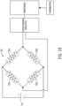
- the strain gauges 70 each include leads 76 connected in a Wheatstone bridge circuit arrangement.
- the strain gauges are connected in the circuit arrangement shown.
- Other circuit arrangements that use more or less strain gauges are possible, such as a half bridge configuration.
- An input current is applied to the bridge circuit and the output voltage of the circuit is proportional to the torsional force (torque) applied to the crank axle by the rider pedaling the left crank arm (in the example shown), as the strain gauges change resistance as they are placed in tension or compression.
- strain gauges 70A and 70B are placed in tension and the resultant resistance change is converted to an output voltage related to the torque.
- the output voltage may be applied to some form of conditioning and amplification circuitry, such as a differential amplifier and filter that will provide an output voltage to the processor. It is further possible to use an analog to digital converter to convert and condition the signal.
- the printed circuit board supporting the Wheatstone bridge, the processor, conditioning, amplification, wireless transmitter, etc. is supported within the axle.
- leads, also within the axle, from the strain gauge PCB may extend to the main PCB. Either a torque value that needs to be converted to power, or power values are wirelessly transmitted from the transmitter.
- the crank assembly includes a second power measurement device associated with the opposing crank.
- the power delivered by the rider to the left crank 12A is measured within the crank axle 14 whereas the power delivered by the rider to the right 12B, opposing, crank is measured by a set of separate strain gauges 26 mounted on the right crank.
- strain gauges are mounted on the right crank and the leads are connected to a Wheatstone bridge circuit to generate an output voltage indicative of torque.
- the Wheatstone bridge and other processing components may be located on a PCB 28 within the axle 14. In such an arrangement, leads from the strain gauge mounted on the crank arm extend into the axle and are connected with a separate Wheatstone bridge. Alternatively, and as discussed hereafter, separate electronics may be mounted on the crank along with the strain gauges.
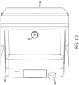
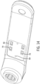
- a power measurement device 30 is mounted on a crank arm 32.
- the crank arm 32 shown is particularly suited for an indoor cycling (IC) bicycle; however, the crank arm may be used on other forms of exercise bicycles, whether upright, recumbent, or otherwise, may be used with bicycles, may be used with other forms of fitness equipment that employ a crank arm, such as elliptical trainers, stair climbing machines, and the like, and may be used with any device that includes a crank arm and where power measurement or the components of power measurement (e.g. torque, force, RPM) may be desired or otherwise beneficial.
- IC indoor cycling
- the crank arm may be used on other forms of exercise bicycles, whether upright, recumbent, or otherwise, may be used with bicycles, may be used with other forms of fitness equipment that employ a crank arm, such as elliptical trainers, stair climbing machines, and the like, and may be used with any device that includes a crank arm and where power measurement or the components of power measurement (e.g. torque, force, RPM)
- the power measurement device 30 includes a housing 34 secured to an inside portion 38 of the crank arm between a bottom bracket aperture 40 and a pedal aperture 42.
- Various power measurement electronics are provided within the housing.
- the inside portion 38 of the crank arm, where the housing 34 is mounted, is that portion adjacent or facing the bicycle frame, drive sprocket, etc.
- the housing 34 may also be secured to other portions of the crank arm, such as the top, bottom or outside portion.
- securing the housing to the inside portion of the crank arm shields the housing and attendant power measurement components from inadvertent contact with a rider or other obstacle. For example, if a rider's foot were to slip off the pedal, the foot could contact the housing if it was secured to some other portion of the crank arm. However, on the inside of the crank arm, the rider's foot would not contact the housing.
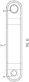
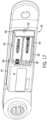
- the housing 34 includes a mounted portion 44 and a cantilever portion 46.
- the mounted portion 34 is secured, such as through a pair of bolts 48, to a machined recess 50 in the crank arm. It is also possible to attach the housing 34 to the crank using tape, adhesive or other mechanisms.
- one or more strain gauges are mounted to the crank arm within the machined recess 50.
- the mounted portion 44 defines a male portion with a circumferential flange 52 such that the male portion is dimensioned to fit snugly within the machined recess.
- a gasket 54 may be provided in a circumferential channel defined in the mounted portion adjacent the crank. When assembled, the gasket is sandwiched between the mounted portion of the housing and the crank arm to block moisture, such as sweat from a rider and water or mud from a trail or road, from entering into the recessed area or into the housing.
- the mounted portion further defines a cavity 56 within which are provided a circuit board 58, reed switch 60 (attached to the circuit board) and a port 62 by which electrical components on the circuit board may be accessed or otherwise communicated with to download software or firmware updates as well as to access information.
- the various electrical components that process the strain gauge outputs and transmit the data are located within the cavity of the housing.
- the pair of bolts 48 extend through the mounted housing and are secured to matching threaded apertures 64 defined in the recessed portion of the crank.
- the printed circuit 58 board extends between and is connected to a pair of molded cylinders 46 through which the bolts 48 pass.
- the molded cylinders 66 form an integral part of the mounted portion 44 of the housing and extend between an outer wall 68 of the mounted portion and the recess in the crank arm.
- the cylinders may be dimensioned so that it engages the crank and prevents the housing from being cracked while tightening the bolts.
- the power assembly 30 discussed herein may also be adhered, non-mechanically fastened, to any form of existing crank arm without modifying the crank.
- the power assembly housing may or may not include a cantilever portion and will not include a male portion configured to engage a recess.
- Strain gauges may be adhered directly to a particular crank wall, without physical modification of the side wall. Some surface preparation (cleaning, etc.) may be required before adhering the strain gauges to the crank wall, however.
- a lower surface of the power assembly housing will define an opening suitable to cover the strain gauges and receive leads connected to the strain gauges.
- the lower surface and/or wall engaging the crank arm surface may be contoured to match the crank arm wall contour of a given crank arm.
- a plurality of different adapters may be fabricated so that a common power assembly housing may mate to different crank arms.
- adapter may have a first side that has a matching contour of a given crank arm, and a second side that has a matching contour of the common power assembly housing.
- the housing in any given configuration includes the processor, batteries, and wireless transmission capability.
- the system may be mated to any of a variety of existing crank arms without modification of the crank arm (e.g., without tapping the crank arm to accept bolts which could effect the structural integrity of the crank), and the power assembly will wireless transmit a power value that may be used to display the power being exerted while riding and/or exercising on a device including the crank.
- the power assembly will wireless transmit a power value that may be used to display the power being exerted while riding and/or exercising on a device including the crank.
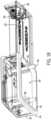
- one or more strain gauges 70 may be provided within the recessed portion 50 of the crank arm.
- two pair of strain gauges are shown with one member of each pair disposed equidistant from a centerline 72 of the crank arm to an opposing pair.
- the strain gauges are placed on the inside wall of the crank arm.
- the strain gauges are glued to a smooth flat surface of the crank. While a machined or otherwise provided recess is shown, the power measurement apparatus may be applied to an existing crank arm with little or no preprocessing of the crank arm.
- the machined recess 50 is provided with a smooth flat bottom upon which the strain gauges are secured.
- a template may be used to apply the strain gauges to the crank surface within the machined recess.
- the strain gauge may be pre-mounted on a substrate in a desired configuration, and the substrate mounted to the crank.
- the side walls of the machined recess also provide a convenient way to locate the housing.
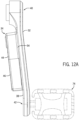
- the strain gauges 70 are placed relatively closer to where the crank is mounted 40 at the bottom bracket 65 compared to where torque is applied to the crank arm at the pedal 74.
- the strain gauges 70 placed relatively closer to the pivot point of the crank arm (i.e., the bending point of the theoretical beam)
- there is greater strain gauge output resolution providing a larger output voltage of the Wheatstone bridge circuit, discussed herein, compared to having the strain gauges been placed relatively closer to the pedal point given the same torque.
- the output voltage is large relative to noise and other spurious voltage outputs; therefore, the circuit requires relatively less filtering, amplification and the like to accurately extract the voltage reading of the circuit.
- the strain gauges 70 may be placed on the same wall of the crank arm and are arranged in the same relative direction.
- the strain gauges are each parallel to the other gauges.
- each strain gauge defines a longitudinal axis across which the strain gauge is response to tension or compression.
- Each of the strain gauges is arranged such that the longitudinal axes are parallel.
- the upper strain gauges (70A and 70B) will be in tension while the lower strain gauges (70C and 70D) will be placed in compression.
- the arrangement through its geometry, filters out forces not relevant to measuring power applied to the cranks causing rotation about the bottom bracket. For example, should a transverse force (e.g.
- the strain gauges are positioned on the same wall or surface of the crank arm 32.
- the strain gauges 70 are each on an inside wall of the crank arm.
- the inside wall is the wall facing an opposing crank or otherwise the frame of the exercise bicycle when the crank is assembled on the exercise bicycle.
- the assembly can be positioned on other walls, depending on the configuration.
- the inside wall provides some protection from inadvertent contact.
- the inside wall (or opposite outside wall) experiences less deflection during riding as compared to the upper and lower walls (those walls or surfaces connecting the inside and outside walls). Placing the strain gauges on those upper and/or lower walls, would provide greater strain gauge bridge output for the same forces thereby providing potentially higher resolution bridge outputs. Nonetheless, those walls are potentially at risk for much greater inadvertent contact, whether on an indoor bike or outside bike.
- the strain gauges 70 each include leads 76 connected in a Wheatstone bridge circuit arrangement.
- the strain gauges are connected in the circuit arrangement shown.
- Other circuit arrangements are possible that use more or less strain gauges, such as a half bridge configuration.
- the strain gauges, processor, and transmitter may be placed in the crank axle or in the crank housing.
- An input voltage is applied to the bridge circuit and the output voltage of the circuit is proportional to the tangential bending force (torque) applied to the crank arm.
- the output voltage may be applied to some form of conditioning and amplification circuitry, such as a differential amplifier and filter that will provide an output voltage to the processor. It is further possible to use an analog to digital converter to convert and condition the signal.
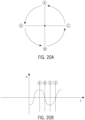
- the output voltage of the Wheatstone bridge circuit is proportional to the torque applied and also indicative of the direction of rotation and the crank position.
- the output of the second Wheatstone bridge will be a sinusoid with the highest output voltage with the crank approximately horizontal and a downward force applied to the crank arm (crank position A, Fig. 20B ).
- crank position B the voltage will typically be about 0, as the crank moves upward to horizontal (crank position C) the voltage will be slightly negative.
- the opposing crank arm pushes the measured arm up against some weight of the rider's leg (typically riders do not pull upward on the cranks, the opposing leg hence uses some force to push the opposing crank arm upward against the opposing leg), and as the crank moves through the upward vertical position (crank position D) the output voltage will transition from a negative value to a positive value, and reach its peak output again as the crank is rotated through horizontal (crank position A).
- the first set of strain gauge and first Wheatstone bridge circuit (associated with the crank axle) will generate a similar sinusoid, except it will be about 180 degrees out of phase with the sinusoid of Figs. 20A and 20B because the cranks are 180 degrees out of phase.
- a separate device may include a wireless receiver, an additional processor and a display.
- the power doubling occurs within the power measurement device (within the crank housing or at the crank), by the appropriate processor or otherwise, and the power value wirelessly transmitted by the device includes the doubling.
- the power measurement device may work with a proprietary display device or may work with third party devices that implicitly expect a value that accounts for both legs and has no inherent functionality to double a value.
- the device may wireless transmit the single leg (crank) power value and doubling may occur at the display processor or related display electronics.
- the display is configured to sum the power values wireless received, when separate power measurement devices are each mounted on the crank arm and crank axle to provide distinct crank arm power measurements.
- the power calculations/measurements displayed are indicative of the total power output by a given rider. Measuring power of only one leg, while theoretically not as precise as separate devices for each leg, nonetheless has several advantages.
- retrofitting and maintaining the power measurement device is far less complicated and costly compared to a similar implementation with two devices. So, for example, with respect to the spindle based power measurement, an existing crank set may simply be retrofitted with a power measurement equipped spindle.
- the device set out herein may be calibrated such that power measurements across machines is consistent. With such consistency, whether across machines or not, a given rider can measure overall relative riding differences.
- a reed switch 60 is included in the power measurement device and a magnet (not shown) may be placed on the frame of whatever device the crank is attached such that the reed switch closes as it passes the magnet.
- the time between two pulses of the reed switch indicate one complete revolution of a crank.
- the pulses can be converted to a revolution per minute measurement.
- the instantaneous torque is measured by the strain gauges with the output voltage of the strain gauges being converted to a power value for display.
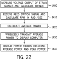
- the voltage output of the strain gauges is provided to the processor (operation 1400).
- the output of the second circuit is a measure of torque and therefore is converted to power through obtaining a radians/sec value.
- the output of the first circuit is a measure of the torsion on the spindle produced by the crank. Power may be calculated similarly for either value.
- the voltage output may first be converted to a digital value through an analog to digital converter.
- power watts
- the reed switch and/or the accelerometer provide data indicative of each revolution of the crank arms.
- the processor obtains a revolutions per minute value in radians per second (operation 1410).
- a pulse is receive at each revolution of the crank arm, and the pulse to converted to revolutions per minute through comparison with the processor clock.
- power is calculated.
- power is sampled at 32 Hz, and converted and wirelessly transmitted (operation 1430) to the display using the ANT+ protocol developed by Dynastream Innovations, Inc.
- the transmitter is shown as a discrete component within the housing, it is possible that it, along with other electrical components, might be provided in the processor within the axle or the crank housing.
- the processor may be implemented as an ASIC, as computer executable instructions in a memory attached to the processor, as a customized circuit, etc.
- other protocols and wireless transmission mechanism may be employed.
- the transmitter may send Bluetooth messages, and in such an arrangement messages may be sent to the processor with the axle or the crank since Bluetooth is bidirectional.
- the average power is displayed (operation 1440) over a number of samples as opposed to an average across all samples.
- large changes in power associated with rapid acceleration for example, may be captured but rapidly changing fluctuations between power measurements are filtered by the averaging.
- a rolling average of the most recent 64 measurements is displayed.
- the most recent 64 power measurements are summed and divided by 64 to display average power.
- the power measurement device transmits instantaneous power measurements at 32 Hz and those measurements are doubled (to account for the opposing crank without a power measurement device).
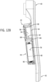
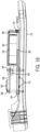
- a cantilevered portion 46 of the housing adjacent the mounted portion 44 is a cantilevered portion 46 of the housing.
- the cantilevered portion 46 extends from the mounted portion 44 along the crank arm body toward the pedal aperture 42.
- the cantilevered portion 46 houses batteries 78 and connection points to provide power to the electrical components within the mounted portion of the housing.
- the cantilevered portion defines a substantially flat bottom adjacent, but not touching, the inside portion of the crank arm. Because the crank arm does bend during usage albeit only slightly, cantilevering a portion of the housing provides several advantages.
- the cantilevered portion is not bolted to the crank arm.
- the bending distance between the bolts on the mounted portion relative to a bolt on the cantilevered portion could potentially cause the housing to crack, to loosen the bolts, or to damage some internal components.
- the cantilevered portion 46 includes a base portion 82 that extends from and is integral to the mounted portion.
- the base portion 82 includes opposing side walls 84 and a front wall 86 distal a midwall 88 of the mounted portion.
- Battery contact points 80 are provided at the front wall and the midwall and batteries are positioned therebetween. Wires are connected to the contact points and routed to the circuit board to provide power to the various components coupled thereto.
- a cover 90 is snap fit to the base portion and may further be secured by a small screw 92 engaging a threaded aperture in the front wall.
- the embodiment shown includes two AA batteries, which are well suited for a club environment for ease of exchange and long life. It is also possible to use smaller watch style (coin) batteries or other types of power supply.
- an accelerometer which may be a two or three axis accelerometer, may be used alone or in conjunction with the reed switch.
- An accelerometer may be used to provide both crank position and rpm measurements. Namely, for example, in a two axis accelerometer or a three axis accelerator where two of the three axes are used, one axis may be aligned with the crank arm and the other axis oriented at 90 degrees to the crank arm. Accordingly, one axis will output a value commensurate with the g-force experienced by the crank and the other axis will output a value 90 degrees out of phase with the first.
- the accelerometer By knowing the axis associated with the crank and whether attached to the left or right crank, the accelerometer, will output a value that is a function of the crank position among other factors. Further by comparing the output of the other axis, it can be determined whether the cranks are being pedaled forward or backward.
- a thermistor is operably associated with the processor. Strain gauges, the crank material, and other components are affected by temperature. Accordingly, it is possible that when a power assembly is exposed to significant temperature variations, such as during a ride that commences early in the morning and continues as the outside temperature increases, the power output delivered by the device would vary based on temperature. In such situations, the device may output different power values due to temperature even when the rider is cranking at the same power. So, a rider cranking along at 150 watts in the early morning would have a power reading of 150 watts, and the same rider cranking along at 150 watts after it has warmed up outside may only have a power reading of 100 watts.
- the thermistor can be used to provide temperature compensation to the power value and thereby reduce or eliminate the temperature effect on the power calculation.
- the Wheatstone bridge circuit provides its voltage output to an analog-to-digital converter to convert the voltage to a digital value.
- the thermistor also outputs its voltage to the analog-to-digital converter to convert the voltage to a digital value. These values are then input to the processor. Therefore, the processor receives a digital power value and a digital temperature value.
- the processor which is coupled with a memory and/or includes on-board memory, has a power curve and may also have a temperature curve (for those embodiments including a thermistor).
- Each curve may be established by measuring the output of the A-to-D converter at two known values (e.g., two known forces on the pedal or two known temperatures). Since the curves are typically straight line curves, two values are sufficient to determine the slope of the curve.
- an A-to-D value is compared with the power curve to determine the power being applied to the crank.
- the A-to-D value of the thermistor is used to select a temperature offset value (or compensation value) from the temperature curve to apply to the power value.
Landscapes
- Engineering & Computer Science (AREA)
- Mechanical Engineering (AREA)
- Physics & Mathematics (AREA)
- General Physics & Mathematics (AREA)
- Chemical & Material Sciences (AREA)
- Combustion & Propulsion (AREA)
- Transportation (AREA)
- Health & Medical Sciences (AREA)
- General Health & Medical Sciences (AREA)
- Physical Education & Sports Medicine (AREA)
- Force Measurement Appropriate To Specific Purposes (AREA)
- Arrangements For Transmission Of Measured Signals (AREA)
Applications Claiming Priority (2)
| Application Number | Priority Date | Filing Date | Title |
|---|---|---|---|
| US201261693967P | 2012-08-28 | 2012-08-28 | |
| PCT/US2013/056866 WO2014036011A1 (en) | 2012-08-28 | 2013-08-27 | Apparatus, system and method for power measurement at a crank axle and crank arm |
Publications (4)
| Publication Number | Publication Date |
|---|---|
| EP2890962A1 EP2890962A1 (en) | 2015-07-08 |
| EP2890962A4 EP2890962A4 (en) | 2016-04-20 |
| EP2890962B1 true EP2890962B1 (en) | 2024-08-21 |
| EP2890962C0 EP2890962C0 (en) | 2024-08-21 |
Family
ID=50184252
Family Applications (1)
| Application Number | Title | Priority Date | Filing Date |
|---|---|---|---|
| EP13834075.7A Active EP2890962B1 (en) | 2012-08-28 | 2013-08-27 | Apparatus and method for power measurement at a crank axle and crank arm |
Country Status (3)
| Country | Link |
|---|---|
| EP (1) | EP2890962B1 (enExample) |
| JP (2) | JP2015529330A (enExample) |
| WO (1) | WO2014036011A1 (enExample) |
Families Citing this family (10)
| Publication number | Priority date | Publication date | Assignee | Title |
|---|---|---|---|---|
| WO2015095933A1 (en) * | 2013-12-27 | 2015-07-02 | Breakaway Innovations Pty Ltd | Improvements to cyclic cranked system data gathering |
| AU2015308156B2 (en) * | 2014-08-26 | 2020-03-05 | 4Iiii Innovations Inc. | Adhesively coupled power-meter for measurement of force, torque, and power and associated methods |
| ES2535582B1 (es) * | 2015-01-19 | 2016-01-25 | Rotor Componentes Tecnológicos S.L. | Dispositivo de medición del par y la potencia de pedaleo en una bicicleta |
| JP6460972B2 (ja) * | 2015-12-21 | 2019-01-30 | 株式会社シマノ | クランクアームアッセンブリ |
| US20190100275A1 (en) * | 2017-10-03 | 2019-04-04 | PalTorc, Inc. | Smart crank control for e-bike |
| IT201800005292A1 (it) * | 2018-05-11 | 2019-11-11 | Rilevatore di sforzi/deformazioni per un componente di una trasmissione di bicicletta | |
| JP6954483B2 (ja) * | 2019-01-25 | 2021-10-27 | 株式会社村田製作所 | 把持負荷検出デバイス |
| JP7467216B2 (ja) * | 2020-04-23 | 2024-04-15 | 株式会社シマノ | 人力駆動車用のコンポーネント |
| JP7438837B2 (ja) * | 2020-04-23 | 2024-02-27 | 株式会社シマノ | 人力駆動車用のコンポーネント |
| KR102635106B1 (ko) * | 2022-11-29 | 2024-02-07 | 안찬우 | 운동 기구와 그에 이용되는 내력연결부재 |
Family Cites Families (13)
| Publication number | Priority date | Publication date | Assignee | Title |
|---|---|---|---|---|
| US5027303A (en) * | 1989-07-17 | 1991-06-25 | Witte Don C | Measuring apparatus for pedal-crank assembly |
| US6755095B2 (en) * | 2001-11-23 | 2004-06-29 | Shimano, Inc. | Bicycle crank assembly and assembly tools |
| US7856903B2 (en) * | 2001-11-23 | 2010-12-28 | Shimano, Inc. | Bicycle crank axle with a radial projection |
| US20100093494A1 (en) * | 2006-10-30 | 2010-04-15 | Robert Masterton Smith | Method and apparatus for measuring and monitoring torque exerted during pedalling of a bicycle or the like equipment |
| ITMI20070669A1 (it) * | 2007-04-02 | 2008-10-03 | Campagnolo Srl | Componente di bicicletta strumentato ed unita' di rilevamento per strumentare tale componente |
| US20080245180A1 (en) * | 2007-04-09 | 2008-10-09 | Yuan-Hsin Huang | Assembly structure of treading crank and spindle tube of the bike |
| EP2165171A4 (en) * | 2007-07-06 | 2016-10-05 | Fisher Mark | CRANK ARM WITH VOLTAGE AMPLIFIER |
| US8006574B2 (en) * | 2007-11-06 | 2011-08-30 | Sram, Llc | Crankset based bicycle power measurement |
| US7806006B2 (en) * | 2007-11-08 | 2010-10-05 | Grand Valley State University | Bicycle torque measuring system |
| US8117923B2 (en) * | 2009-05-08 | 2012-02-21 | Shimano Inc. | Bicycle bottom bracket force sensor |
| US9921118B2 (en) * | 2012-01-23 | 2018-03-20 | Foundation Fitness, LLC | Apparatus, system and method for power measurement at a crank axle and crank arm |
| US9417144B2 (en) * | 2011-01-21 | 2016-08-16 | Foundation Fitness, LLC | Apparatus, system and method for power measurement |
| ES2749600T3 (es) * | 2011-07-18 | 2020-03-23 | Grassi Michael J | Sensor de par de torsión |
-
2013
- 2013-08-27 EP EP13834075.7A patent/EP2890962B1/en active Active
- 2013-08-27 WO PCT/US2013/056866 patent/WO2014036011A1/en not_active Ceased
- 2013-08-27 JP JP2015529941A patent/JP2015529330A/ja active Pending
-
2018
- 2018-02-20 JP JP2018027530A patent/JP6466608B2/ja active Active
Also Published As
| Publication number | Publication date |
|---|---|
| JP2015529330A (ja) | 2015-10-05 |
| JP6466608B2 (ja) | 2019-02-06 |
| JP2018138915A (ja) | 2018-09-06 |
| EP2890962A1 (en) | 2015-07-08 |
| WO2014036011A1 (en) | 2014-03-06 |
| EP2890962A4 (en) | 2016-04-20 |
| EP2890962C0 (en) | 2024-08-21 |
Similar Documents
| Publication | Publication Date | Title |
|---|---|---|
| US11885702B2 (en) | Apparatus, system and method for power measurement | |
| US10571349B2 (en) | Apparatus, system and method for power measurement at a crank axle and crank arm | |
| EP2890962B1 (en) | Apparatus and method for power measurement at a crank axle and crank arm | |
| AU2010324542B2 (en) | Cyclic cranked system method and related devices | |
| US11406869B2 (en) | Systems and methods for power meter calibration | |
| US7806006B2 (en) | Bicycle torque measuring system | |
| US9810593B2 (en) | Pedaling torque and power measuring device for a bicycle | |
| JP2015529330A5 (enExample) | ||
| US20110082009A1 (en) | Instrumented handle and pedal systems for use in rehabilitation, exercise and training equipment | |
| EP2739950A2 (en) | Pedaling torque sensor device for each cyclist's leg and power meter apparatus | |
| US11029225B1 (en) | Electronic device, crank assembly with electronic device and drive train including crank assembly with electronic device | |
| US11280689B2 (en) | Apparatus, system and method for power measurement at a crank axle and crank arm | |
| US9964456B2 (en) | System for estimating total power input by a bicyclist using a single sided power meter system | |
| US10065075B2 (en) | Dynamic tire pressure sensor system for a bike | |
| WO2019113105A1 (en) | Systems and methods for power meter calibration | |
| JPH10165556A (ja) | 主に自転車トレーニングのための、サイクリストの身体状態を表すパラメータ表示・記録システム | |
| US20250162678A1 (en) | Crank power measurement system | |
| TW202043093A (zh) | 傳感裝置及使用其的傳感系統與人力驅動裝置 |
Legal Events
| Date | Code | Title | Description |
|---|---|---|---|
| PUAI | Public reference made under article 153(3) epc to a published international application that has entered the european phase |
Free format text: ORIGINAL CODE: 0009012 |
|
| 17P | Request for examination filed |
Effective date: 20150306 |
|
| AK | Designated contracting states |
Kind code of ref document: A1 Designated state(s): AL AT BE BG CH CY CZ DE DK EE ES FI FR GB GR HR HU IE IS IT LI LT LU LV MC MK MT NL NO PL PT RO RS SE SI SK SM TR |
|
| AX | Request for extension of the european patent |
Extension state: BA ME |
|
| DAX | Request for extension of the european patent (deleted) | ||
| RA4 | Supplementary search report drawn up and despatched (corrected) |
Effective date: 20160321 |
|
| RIC1 | Information provided on ipc code assigned before grant |
Ipc: A63B 24/00 20060101ALI20160315BHEP Ipc: G01L 3/24 20060101ALI20160315BHEP Ipc: G01L 5/00 20060101ALI20160315BHEP Ipc: G01L 3/14 20060101ALI20160315BHEP Ipc: G01L 1/22 20060101AFI20160315BHEP Ipc: A63B 22/06 20060101ALI20160315BHEP Ipc: G01L 3/10 20060101ALI20160315BHEP |
|
| STAA | Information on the status of an ep patent application or granted ep patent |
Free format text: STATUS: EXAMINATION IS IN PROGRESS |
|
| 17Q | First examination report despatched |
Effective date: 20181113 |
|
| GRAP | Despatch of communication of intention to grant a patent |
Free format text: ORIGINAL CODE: EPIDOSNIGR1 |
|
| STAA | Information on the status of an ep patent application or granted ep patent |
Free format text: STATUS: GRANT OF PATENT IS INTENDED |
|
| INTG | Intention to grant announced |
Effective date: 20231020 |
|
| RIC1 | Information provided on ipc code assigned before grant |
Ipc: B62M 3/00 20060101ALI20231005BHEP Ipc: B62J 45/411 20200101ALI20231005BHEP Ipc: A63B 22/06 20060101ALI20231005BHEP Ipc: A63B 24/00 20060101ALI20231005BHEP Ipc: B62J 45/421 20200101ALI20231005BHEP Ipc: G01L 5/00 20060101ALI20231005BHEP Ipc: G01L 3/24 20060101ALI20231005BHEP Ipc: G01L 3/10 20060101ALI20231005BHEP Ipc: G01L 1/22 20060101AFI20231005BHEP |
|
| GRAJ | Information related to disapproval of communication of intention to grant by the applicant or resumption of examination proceedings by the epo deleted |
Free format text: ORIGINAL CODE: EPIDOSDIGR1 |
|
| STAA | Information on the status of an ep patent application or granted ep patent |
Free format text: STATUS: EXAMINATION IS IN PROGRESS |
|
| INTC | Intention to grant announced (deleted) | ||
| GRAP | Despatch of communication of intention to grant a patent |
Free format text: ORIGINAL CODE: EPIDOSNIGR1 |
|
| STAA | Information on the status of an ep patent application or granted ep patent |
Free format text: STATUS: GRANT OF PATENT IS INTENDED |
|
| INTG | Intention to grant announced |
Effective date: 20240313 |
|
| GRAS | Grant fee paid |
Free format text: ORIGINAL CODE: EPIDOSNIGR3 |
|
| GRAA | (expected) grant |
Free format text: ORIGINAL CODE: 0009210 |
|
| STAA | Information on the status of an ep patent application or granted ep patent |
Free format text: STATUS: THE PATENT HAS BEEN GRANTED |
|
| AK | Designated contracting states |
Kind code of ref document: B1 Designated state(s): AL AT BE BG CH CY CZ DE DK EE ES FI FR GB GR HR HU IE IS IT LI LT LU LV MC MK MT NL NO PL PT RO RS SE SI SK SM TR |
|
| REG | Reference to a national code |
Ref country code: GB Ref legal event code: FG4D |
|
| REG | Reference to a national code |
Ref country code: CH Ref legal event code: EP |
|
| REG | Reference to a national code |
Ref country code: DE Ref legal event code: R096 Ref document number: 602013086015 Country of ref document: DE |
|
| REG | Reference to a national code |
Ref country code: IE Ref legal event code: FG4D |
|
| U01 | Request for unitary effect filed |
Effective date: 20240923 |
|
| U07 | Unitary effect registered |
Designated state(s): AT BE BG DE DK EE FI FR IT LT LU LV MT NL PT RO SE SI Effective date: 20241015 |
|
| U20 | Renewal fee for the european patent with unitary effect paid |
Year of fee payment: 12 Effective date: 20241015 |
|
| PG25 | Lapsed in a contracting state [announced via postgrant information from national office to epo] |
Ref country code: NO Free format text: LAPSE BECAUSE OF FAILURE TO SUBMIT A TRANSLATION OF THE DESCRIPTION OR TO PAY THE FEE WITHIN THE PRESCRIBED TIME-LIMIT Effective date: 20241121 |
|
| PG25 | Lapsed in a contracting state [announced via postgrant information from national office to epo] |
Ref country code: PL Free format text: LAPSE BECAUSE OF FAILURE TO SUBMIT A TRANSLATION OF THE DESCRIPTION OR TO PAY THE FEE WITHIN THE PRESCRIBED TIME-LIMIT Effective date: 20240821 Ref country code: GR Free format text: LAPSE BECAUSE OF FAILURE TO SUBMIT A TRANSLATION OF THE DESCRIPTION OR TO PAY THE FEE WITHIN THE PRESCRIBED TIME-LIMIT Effective date: 20241122 |
|
| PG25 | Lapsed in a contracting state [announced via postgrant information from national office to epo] |
Ref country code: IS Free format text: LAPSE BECAUSE OF FAILURE TO SUBMIT A TRANSLATION OF THE DESCRIPTION OR TO PAY THE FEE WITHIN THE PRESCRIBED TIME-LIMIT Effective date: 20241221 |
|
| PG25 | Lapsed in a contracting state [announced via postgrant information from national office to epo] |
Ref country code: HR Free format text: LAPSE BECAUSE OF FAILURE TO SUBMIT A TRANSLATION OF THE DESCRIPTION OR TO PAY THE FEE WITHIN THE PRESCRIBED TIME-LIMIT Effective date: 20240821 |
|
| PG25 | Lapsed in a contracting state [announced via postgrant information from national office to epo] |
Ref country code: RS Free format text: LAPSE BECAUSE OF FAILURE TO SUBMIT A TRANSLATION OF THE DESCRIPTION OR TO PAY THE FEE WITHIN THE PRESCRIBED TIME-LIMIT Effective date: 20241121 Ref country code: ES Free format text: LAPSE BECAUSE OF FAILURE TO SUBMIT A TRANSLATION OF THE DESCRIPTION OR TO PAY THE FEE WITHIN THE PRESCRIBED TIME-LIMIT Effective date: 20240821 |
|
| PG25 | Lapsed in a contracting state [announced via postgrant information from national office to epo] |
Ref country code: RS Free format text: LAPSE BECAUSE OF FAILURE TO SUBMIT A TRANSLATION OF THE DESCRIPTION OR TO PAY THE FEE WITHIN THE PRESCRIBED TIME-LIMIT Effective date: 20241121 Ref country code: PL Free format text: LAPSE BECAUSE OF FAILURE TO SUBMIT A TRANSLATION OF THE DESCRIPTION OR TO PAY THE FEE WITHIN THE PRESCRIBED TIME-LIMIT Effective date: 20240821 Ref country code: NO Free format text: LAPSE BECAUSE OF FAILURE TO SUBMIT A TRANSLATION OF THE DESCRIPTION OR TO PAY THE FEE WITHIN THE PRESCRIBED TIME-LIMIT Effective date: 20241121 Ref country code: IS Free format text: LAPSE BECAUSE OF FAILURE TO SUBMIT A TRANSLATION OF THE DESCRIPTION OR TO PAY THE FEE WITHIN THE PRESCRIBED TIME-LIMIT Effective date: 20241221 Ref country code: HR Free format text: LAPSE BECAUSE OF FAILURE TO SUBMIT A TRANSLATION OF THE DESCRIPTION OR TO PAY THE FEE WITHIN THE PRESCRIBED TIME-LIMIT Effective date: 20240821 Ref country code: GR Free format text: LAPSE BECAUSE OF FAILURE TO SUBMIT A TRANSLATION OF THE DESCRIPTION OR TO PAY THE FEE WITHIN THE PRESCRIBED TIME-LIMIT Effective date: 20241122 Ref country code: ES Free format text: LAPSE BECAUSE OF FAILURE TO SUBMIT A TRANSLATION OF THE DESCRIPTION OR TO PAY THE FEE WITHIN THE PRESCRIBED TIME-LIMIT Effective date: 20240821 |
|
| REG | Reference to a national code |
Ref country code: CH Ref legal event code: PL |
|
| PG25 | Lapsed in a contracting state [announced via postgrant information from national office to epo] |
Ref country code: SM Free format text: LAPSE BECAUSE OF FAILURE TO SUBMIT A TRANSLATION OF THE DESCRIPTION OR TO PAY THE FEE WITHIN THE PRESCRIBED TIME-LIMIT Effective date: 20240821 |
|
| PG25 | Lapsed in a contracting state [announced via postgrant information from national office to epo] |
Ref country code: CH Free format text: LAPSE BECAUSE OF NON-PAYMENT OF DUE FEES Effective date: 20240831 |
|
| PG25 | Lapsed in a contracting state [announced via postgrant information from national office to epo] |
Ref country code: CZ Free format text: LAPSE BECAUSE OF FAILURE TO SUBMIT A TRANSLATION OF THE DESCRIPTION OR TO PAY THE FEE WITHIN THE PRESCRIBED TIME-LIMIT Effective date: 20240821 |
|
| PG25 | Lapsed in a contracting state [announced via postgrant information from national office to epo] |
Ref country code: SK Free format text: LAPSE BECAUSE OF FAILURE TO SUBMIT A TRANSLATION OF THE DESCRIPTION OR TO PAY THE FEE WITHIN THE PRESCRIBED TIME-LIMIT Effective date: 20240821 |
|
| REG | Reference to a national code |
Ref country code: GB Ref legal event code: 732E Free format text: REGISTERED BETWEEN 20250410 AND 20250416 |
|
| PLBE | No opposition filed within time limit |
Free format text: ORIGINAL CODE: 0009261 |
|
| STAA | Information on the status of an ep patent application or granted ep patent |
Free format text: STATUS: NO OPPOSITION FILED WITHIN TIME LIMIT |
|
| PG25 | Lapsed in a contracting state [announced via postgrant information from national office to epo] |
Ref country code: MC Free format text: LAPSE BECAUSE OF FAILURE TO SUBMIT A TRANSLATION OF THE DESCRIPTION OR TO PAY THE FEE WITHIN THE PRESCRIBED TIME-LIMIT Effective date: 20240821 |
|
| PGFP | Annual fee paid to national office [announced via postgrant information from national office to epo] |
Ref country code: GB Payment date: 20250612 Year of fee payment: 13 |
|
| U20 | Renewal fee for the european patent with unitary effect paid |
Year of fee payment: 13 Effective date: 20250610 |
|
| PG25 | Lapsed in a contracting state [announced via postgrant information from national office to epo] |
Ref country code: IE Free format text: LAPSE BECAUSE OF NON-PAYMENT OF DUE FEES Effective date: 20240827 |
|
| 26N | No opposition filed |
Effective date: 20250522 |
|
| U1K | Transfer of rights of the unitary patent after the registration of the unitary effect |
Owner name: GIANT MANUFACTURING CO., LTD.; TW |