EP2890818B1 - Verschiebung von abstreifrollen - Google Patents
Verschiebung von abstreifrollen Download PDFInfo
- Publication number
- EP2890818B1 EP2890818B1 EP13750067.4A EP13750067A EP2890818B1 EP 2890818 B1 EP2890818 B1 EP 2890818B1 EP 13750067 A EP13750067 A EP 13750067A EP 2890818 B1 EP2890818 B1 EP 2890818B1
- Authority
- EP
- European Patent Office
- Prior art keywords
- scraping
- primary
- rollers
- displacement
- cover
- Prior art date
- Legal status (The legal status is an assumption and is not a legal conclusion. Google has not performed a legal analysis and makes no representation as to the accuracy of the status listed.)
- Active
Links
Images



Classifications
-
- C—CHEMISTRY; METALLURGY
- C14—SKINS; HIDES; PELTS; LEATHER
- C14B—MECHANICAL TREATMENT OR PROCESSING OF SKINS, HIDES OR LEATHER IN GENERAL; PELT-SHEARING MACHINES; INTESTINE-SPLITTING MACHINES
- C14B1/00—Manufacture of leather; Machines or devices therefor
- C14B1/02—Fleshing, unhairing, samming, stretching-out, setting-out, shaving, splitting, or skiving skins, hides, or leather
- C14B1/04—Fleshing, unhairing, samming, stretching-out, setting-out, shaving, splitting, or skiving skins, hides, or leather using slicking, scraping, or smoothing-out cylinders or blades fixed on supports, e.g. cylinders, in a plane substantially at right angles to the working surface
- C14B1/10—Fleshing, unhairing, samming, stretching-out, setting-out, shaving, splitting, or skiving skins, hides, or leather using slicking, scraping, or smoothing-out cylinders or blades fixed on supports, e.g. cylinders, in a plane substantially at right angles to the working surface in machines with drums with cylindrical, conical, or similar surfaces for supporting the whole working piece
-
- C—CHEMISTRY; METALLURGY
- C14—SKINS; HIDES; PELTS; LEATHER
- C14B—MECHANICAL TREATMENT OR PROCESSING OF SKINS, HIDES OR LEATHER IN GENERAL; PELT-SHEARING MACHINES; INTESTINE-SPLITTING MACHINES
- C14B15/00—Mechanical treatment of furs
-
- C—CHEMISTRY; METALLURGY
- C14—SKINS; HIDES; PELTS; LEATHER
- C14B—MECHANICAL TREATMENT OR PROCESSING OF SKINS, HIDES OR LEATHER IN GENERAL; PELT-SHEARING MACHINES; INTESTINE-SPLITTING MACHINES
- C14B17/00—Details of apparatus or machines for manufacturing or treating skins, hides, leather, or furs
- C14B17/02—Blading cylinders or other working cylinders, e.g. slicking or scraping cylinders
Definitions
- the present invention relates to an apparatus for processing the skin side of a tubular pelt from a fur animal, in particular from a mink.
- Scraping rollers of apparatuses for processing of the skin side of pelts of fur animals, such as mink or foxes are worn during use so that the scraping edges or teeth become dull. For that reason, it is necessary to replace the scraping rollers in the apparatus after a certain number of pelts have been processed (see closest prior art document WO 2011/116771 , upon which the preamble of claim 1 is based).
- the scraping rollers By displacing at least one of the scraping rollers of the apparatus but preferably more, such as all scraping rollers of the scraping device away from the mandrel, the scraping rollers become much more accessible for manual interaction such as for replacing the scraping rollers.
- the displacement means are arranged for displacement of the at least one scraping roller in a substantially rectilinear movement, i.e. in a substantially straight movement along the axis of rotation of the individual roller.
- the least space is required within the interior of the apparatus to give room for displacement of the scraping roller or rollers and it is in particular advantageous where a cover is provided for enclosing the scraping device and a part of the mandrel and taking up debris that is removed from the skin side of the pelt by the scraping rollers.
- the displacement means are preferably arranged for displacement of the at least one scraping roller in a direction which is substantially perpendicular to the longitudinal direction of the mandrel.
- the displacement direction will also be slanted correspondingly.
- the displacement means are preferably arranged for displacement of the at least one scraping roller over a distance in the direction of the axis of rotation of the scraping roller that is at least twice the extent of the scraping roller in said direction, in particular between two and three times the extent of the scraping roller in the direction of its axis of rotation.
- the extent of the scraping rollers in the direction of the axis of rotation is normally in the range of 140 to 165 millimetres.
- the displacement means are in particular arranged for displacement of the at least one scraping roller over a distance in the direction of the axis of rotation of the scraping roller that is in the range of 150 to 700 millimetres, preferably 200 to 600 millimetres.
- the displacement means are arranged for simultaneous displacement of both rollers of one of said set of primary scraping rollers in the same direction and in particular that the displacement means are arranged for displacement of both rollers of said set of primary scraping rollers over the same distance.
- the displacement means may further be arranged for displacement of the other set of primary scraping rollers in a direction perpendicularly to the direction of displacement of the first set of primary scraping rollers.
- the displacement means are arranged for displacement of the set of secondary scraping rollers.
- the apparatus according to the present invention may comprise a cover having a compartment and an outlet, wherein said cover is configured for enclosing a part of the mandrel and at least one set of primary scraping rollers of the scraping device in said compartment during operation, wherein said outlet is arranged in a bottom part of said cover, said bottom part being arranged below said set of primary scraping rollers, wherein said cover comprises walls with inner surfaces configured for leading material removed from said skin side by means of said set of primary scraping rollers towards said bottom part, and wherein the displacement means are arranged for displacing said set of primary scraping rollers out from the compartment of the cover.
- the cover encloses preferably both sets of primary scraping rollers in said compartment, and the displacement means are arranged for displacing both sets of primary scraping rollers out from the compartment of the cover.
- the cover is common to all scraper rollers of the scraping device and wherein the displacement means are arranged for displacing all scraping rollers out from the compartment of the cover.
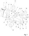
- Fig. 1 The apparatus of the present invention of which some parts only are shown in Fig. 1 comprises an mandrel 1 which is tapering towards a thinner, free end 2 from which the tubular pelt 3 is drawn over the mandrel and a thicker end 4 which is connected to and supported by the frame of the apparatus (not shown) where the drive means are arranged for driving the mandrel 1 in the longitudinal direction thereof during operation of the apparatus for scraping the skin side 5 of the pelt 3 arranged on the mandrel 1.
- the apparatus comprises two sets of primary scraping rollers 6, 7, 8, 9 having V-shaped teeth 10 and drive means 11, 12, 13, 14 for driving the scraping rollers 6, 7, 8, 9 in a rotation about corresponding axes.
- the apparatus further comprises biasing means (not shown) for biasing the teeth 10 of the scraping rollers 6, 7, 8, 9 towards the skin side 5 of the pelt 3 during operation of the apparatus.
- the apparatus shown in Fig. 1 further comprises a set of secondary scraping rollers 15, 16 having helical teeth 17 for performing an improved scraping of the areas around and in particular beneath the part 18 of the pelt 3 that used to cover the front legs of the fur animals from which the pelt 3 was taken.
- the secondary scraping rollers 15, 16 are driven by secondary drive means 19, 20.
- the drive means 11, 12, 13, 14, 19, 20 of each set of scraping rollers 6, 7, 8, 9, 15, 16 are arranged so that the drive shafts 21 carrying the scraping rollers 6, 7, 8, 9, 15, 16 extend to the same side for each set.
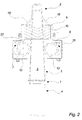
- the displacement of a scraping roller 6, 7, 8, 9, 15, 16 in a direction parallel to its axis of rotation for replacement of the scraping roller 6, 7, 8, 9, 15, 16 is generally relevant as the construction of such apparatus normally leaves only little space for working on the scraping rollers 6, 7, 8, 9, 15, 16 when they are in the operating position, but it becomes particularly advantageous when the apparatus comprises a cover 21 as shown in the embodiment of Fig. 2 , where the secondary scraping rollers 15, 16 are omitted.
- the outlet 23 is arranged in a bottom part of said cover 21 below both sets of primary scraping rollers 6, 7, 8, 9 and the cover 21 comprises walls with inner surfaces configured for leading the material removed from the skin side 5 of the pelt 3 towards the outlet at the bottom part, where suction means (not shown) are arranged to remove the debris from the outlet 23.
- the displacement means of the apparatus are arranged for displacing both sets of primary scraping rollers 6, 7, 8, 9, out from the compartment 22 of the cover 21.
- the cover 21 is provided with suitable openings 24, 25 for allowing the mandrel 1 with the pelt 3 arranged thereon to pass through the cover 21 and roller openings 26, 27, 28, 29 for the primary scraping rollers 6, 7, 8, 9 to extend into the compartment 22 of the cover 21.
- the roller openings 26, 27, 28, 29 are arranged so that sets of primary scraping rollers 6, 7, 8, 9 extend into the compartment 22 from the same side and therefore may be displaced out from the compartment 22 simultaneous, e.g. on a moveable frame on which both primary scraping rollers 6, 7, 8, 9 of the set as well as their drive means 11, 12, 13, 14 are arranged.
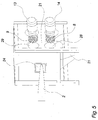
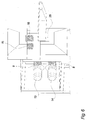
- FIG. 4 A perspective side view of an apparatus is shown in Fig. 4 with the drive means 13, 14 for a horizontal set of primary scraping rollers in an operating position, and in Fig. 5 is shown a perspective view corresponding to Fig. 4 where the set of primary scraping rollers 8, 9 are in a displaced position, so that the scraping rollers 8, 9 may be replaced from the drive shafts of the drive means 13, 14.
- FIG. 6 Another perspective view of the apparatus is shown in fig. 6 , where the set of secondary scraping rollers 15, 16 are in a displaced position, and the horizontal set of primary scraping rollers 8, 9 also are in a displaced position. Finally, in a side view of the apparatus in Fig. 7 is the other set of primary scraping rollers 6, 7 as well as the set of secondary scraping rollers 15, 16 shown in a displaced position.
Landscapes
- Engineering & Computer Science (AREA)
- Mechanical Engineering (AREA)
- Chemical & Material Sciences (AREA)
- Organic Chemistry (AREA)
- Manufacturing & Machinery (AREA)
- Massaging Devices (AREA)
Claims (12)
- Vorrichtung zur Verarbeitung der Hautseite (5) eines rohrförmigen Pelzes (3), welche Vorrichtung Folgendes umfassteinen länglichen konusförmigen Dorn (1) zur Unterstützung des Pelzes (3) mit der Hautseite nach außen, wobei der Dorn (1) ein dünneres, freies Ende (2), von dem der rohrförmige Pelz (3) über den Dorn (1) gezogen wird, und ein dickeres Ende (4) aufweist,eine Schabereinrichtung umfassend einen ersten Satz von primären Schaberrollen (6, 7), die auf entgegengesetzten Seiten des Dorns (1) angeordnet sind, und einen zweiten Satz von primären Schaberrollen (8, 9), die auf anderen entgegengesetzten Seiten des Dorns (1) angeordnet und im Wesentlichen senkrecht zum ersten Satz von Schaberrollen (6, 7) ausgerichtet sind, wobei die Schabereinrichtung weiter primäre Drehmittel (11, 12, 13, 14) zum Drehen der primären Schaberrollen (6, 7, 8, 9) während der Verarbeitung eines Pelzes (3), um mit einer Hautseite des Pelzes (3) in Eingriff zu gehen, umfasst,Bewegungsmittel zum Ausführen einer relativen Bewegung zwischen der Schabereinrichtung und dem Dorn (1) in der Längsrichtung des Dorns (1),dadurch gekennzeichnet, dass
die Vorrichtung weiter Verlagerungsmittel zum Verlagern mindestens einer primären Schaberrolle (6, 7, 8, 9) zusammen mit ihren primären Drehmitteln (11, 12, 13, 14) in Richtung der Drehachse der Schaberrolle (6, 7, 8, 9) umfasst. - Vorrichtung nach Anspruch 1, wobei die Verlagerungsmittel zum Verlagern der mindestens einen primären Schaberrolle (6, 7, 8, 9) zusammen mit den entsprechenden primären Drehmitteln (11, 12, 13, 14) in einer im Wesentlichen geradlinigen Bewegung eingerichtet sind.
- Vorrichtung nach Anspruch 1 oder 2, wobei die Verlagerungsmittel zum Verlagern der mindestens einen primären Schaberrolle (6, 7, 8, 9) zusammen mit den entsprechenden primären Drehmitteln (11, 12, 13, 14) in einer zur Längsrichtung des Dorns (1) im Wesentlichen senkrechten Richtung eingerichet sind.
- Vorrichtung nach einem der Ansprüche 1 bis 3, wobei die Verlagerungsmittel zum Verlagern der mindestens einen primären Schaberrolle (6, 7, 8, 9) zusammen mit den entsprechenden primären Drehmitteln (11, 12, 13, 14) über eine Strecke in Richtung der Drehachse der Schaberrolle (6, 7, 8, 9), die mindestens zweimal der Erstreckung der Schaberrolle (6, 7, 8, 9) in der Richtung ist, eingerichtet sind.
- Vorrichtung nach einem der vorgehenden Ansprüche, wobei die Verlagerungsmittel zum Verlagern der mindestens einen Schaberrolle (6, 7, 8, 9) zusammen mit den entsprechenden primären Drehmitteln (11, 12, 13, 14) über eine Strecke in Richtung der Drehachse der Schaberrolle (6, 7, 8, 9), die im Bereich 150 bis 700 Millimeter, vorzugsweise 200 bis 600 Millimeter ist, eingerichtet sind.
- Vorrichtung nach einem der vorgehenden Ansprüche, wobei die Verlagerungsmittel zum gleichzeitigen Verlagern von beiden Rollen (6, 7, 8, 9) von einem des Satzes von primären Schaberrollen (6, 7, 8, 9) in der gleichen Richtung eingerichtet sind.
- Vorrichtung nach Anspruch 6, wobei die Verlagerungsmittel zum Verlagern von beiden Rollen (6, 7, 8, 9) des Satzes von primären Schaberrollen (6, 7, 8, 9) über die gleiche Strecke eingerichtet sind.
- Vorrichtung nach Anspruch 6 oder 7, wobei die Verlagerungsmittel weiter zum Verlagern des anderen Satzes von primären Schaberrollen (6, 7, 8, 9) in einer Richtung senkrecht zur Verlagerungsrichtung des ersten Satzes von primären Schaberrollen (6, 7, 8, 9) eingerichtet sind.
- Vorrichtung nach einem der Ansprüche 6 bis 8, wobei die Schabereinrichtung weiter mindestens einen Satz von sekundären Schaberrollen (15, 16) und sekundären Drehmitteln (19, 20) zum Drehen der sekundären Schaberrolle (15, 16) umfasst, wobei die Verlagerungsmittel zum Verlagern des Satzes von sekundären Schaberrollen (15, 16) zusammen mit den entsprechenden sekundären Drehmitteln (19, 20) eingerichtet sind.
- Vorrichtung nach einem der vorgehenden Ansprüche, umfassend eine Abdeckung (21) mit einer Kammer (22) und einen Ausgang (23),
wobei die Abdeckung (21) zum Umgeben eines Teils des Dorns (1) und mindestens eines Satzes von primären Schaberrollen (6, 7, 8, 9) der Schabereinrichtung in der Kammer (22) während des Betriebs ausgeformt ist,
wobei der Ausgang (23) im unteren Teil der Abdeckung (21) angeordnet ist, wobei der untere Teil unter dem Satz von primären Schaberrollen (6, 7, 8, 9) angeordnet ist,
wobei die Abdeckung (21) Wände mit Innenflächen umfasst, die zum Führen von von der Hautseite entferntem Material mittels des Satzes von primären Schaberrollen (6, 7, 8, 9) gegen den unteren Teil ausgeformt sind, und
wobei die Verlagerungsmittel zum Verlagern des Satzes von primären Schaberrollen (6, 7, 8, 9) aus der Kammer (22) der Abdeckung (21) heraus eingerichtet sind. - Vorrichtung nach Anspruch 10, wobei die Abdeckung (21) die beiden Sätze von primären Schaberrollen (6, 7, 8, 9) in der Kammer (22) umgibt, und wobei die Verlagerungsmittel zum Verlagern von den beiden Sätzen von primären Schaberrollen (6, 7, 8, 9) aus der Kammer der Abdeckung heraus eingerichtet sind.
- Vorrichtung nach Anspruch 10 oder 11, wobei die Abdeckung (21) für alle Schaberrollen (6, 7, 8, 9, 15, 16) der Schabereinrichtung gemeinsam ist, und wobei die Verlagerungsmittel zum Verlagern von allen Schaberrollen (6, 7, 8, 9, 15, 16) aus der Kammer (22) der Abdeckung (21) heraus eingerichtet sind.
Priority Applications (1)
| Application Number | Priority Date | Filing Date | Title |
|---|---|---|---|
| PL13750067T PL2890818T3 (pl) | 2012-08-30 | 2013-08-16 | Przesuw frezów mizdrujących |
Applications Claiming Priority (2)
| Application Number | Priority Date | Filing Date | Title |
|---|---|---|---|
| DKPA201270525A DK177495B1 (en) | 2012-08-30 | 2012-08-30 | Displacement of scraping rollers |
| PCT/EP2013/067106 WO2014032987A1 (en) | 2012-08-30 | 2013-08-16 | Displacement of scraping rollers |
Publications (2)
| Publication Number | Publication Date |
|---|---|
| EP2890818A1 EP2890818A1 (de) | 2015-07-08 |
| EP2890818B1 true EP2890818B1 (de) | 2016-10-19 |
Family
ID=48794275
Family Applications (1)
| Application Number | Title | Priority Date | Filing Date |
|---|---|---|---|
| EP13750067.4A Active EP2890818B1 (de) | 2012-08-30 | 2013-08-16 | Verschiebung von abstreifrollen |
Country Status (7)
| Country | Link |
|---|---|
| US (1) | US9631247B2 (de) |
| EP (1) | EP2890818B1 (de) |
| CA (1) | CA2883597A1 (de) |
| DK (2) | DK177495B1 (de) |
| LT (1) | LT2890818T (de) |
| PL (1) | PL2890818T3 (de) |
| WO (1) | WO2014032987A1 (de) |
Families Citing this family (3)
| Publication number | Priority date | Publication date | Assignee | Title |
|---|---|---|---|---|
| DK177568B1 (en) * | 2012-03-28 | 2013-10-28 | Jasopels As | A cover arrangement for an apparatus for processing fur |
| DK178093B1 (da) * | 2013-09-16 | 2015-05-11 | Hedensted Gruppen As | Apparat til skrabning af kødsiden af pelsdyrskind |
| DK178710B1 (en) * | 2015-08-17 | 2016-11-28 | Eikon Tech Holding S À R L | Pelt board and the use thereof |
Family Cites Families (11)
| Publication number | Priority date | Publication date | Assignee | Title |
|---|---|---|---|---|
| US2896438A (en) * | 1955-02-25 | 1959-07-28 | Paul Autio | Scraping appliance, particularly for mink-skins |
| US3048995A (en) * | 1961-07-25 | 1962-08-14 | Clarence E Browning | Pelt fleshing machine |
| SU349312A1 (ru) * | 1971-03-02 | 1974-01-15 | Опытно конструкторское бюро научно исследовательского института | УСТРОЙСТВО дл МЕЗДРЕНИЯ ШКУРОК |
| DK78286D0 (da) | 1986-02-20 | 1986-02-20 | Bent Juul Larsen | Apparat til fjernelse af fedtlag fra pelshuders koedside |
| DK156669C (da) | 1986-02-20 | 1990-02-12 | Granly Trykluft Aps | Fremgangsmaade og apparat til fjernelse af fedt og koed fra koedsiden paa skindet eller pelsen fra et pelsdyr_og rulle til brug i et saadant apparat |
| SE465466B (sv) * | 1986-05-16 | 1991-09-16 | Ingvar Johansson | Anordning foer skrapning av skinn |
| FI105107B (sv) | 1996-09-16 | 2000-06-15 | Granbaeck Leif | Förfarande och anordning för styrning av skraptrycket vid avskrapning av skinnstycken |
| ATE502124T1 (de) * | 2008-02-21 | 2011-04-15 | Pamutec Patents Aps | Vorrichtung zur fellverarbeitung |
| WO2011116771A1 (en) * | 2010-03-24 | 2011-09-29 | 4M Globe Management Ltd | Apparatus for processing fur |
| DK201100055Y6 (da) | 2010-08-13 | 2012-01-13 | 4M Globe Man Ltd | Apparat til behandling af pelsdyrskind |
| DK177568B1 (en) * | 2012-03-28 | 2013-10-28 | Jasopels As | A cover arrangement for an apparatus for processing fur |
-
2012
- 2012-08-30 DK DKPA201270525A patent/DK177495B1/en active
-
2013
- 2013-08-16 EP EP13750067.4A patent/EP2890818B1/de active Active
- 2013-08-16 WO PCT/EP2013/067106 patent/WO2014032987A1/en not_active Ceased
- 2013-08-16 CA CA2883597A patent/CA2883597A1/en active Pending
- 2013-08-16 PL PL13750067T patent/PL2890818T3/pl unknown
- 2013-08-16 LT LTEP13750067.4T patent/LT2890818T/lt unknown
- 2013-08-16 US US14/423,977 patent/US9631247B2/en not_active Expired - Fee Related
- 2013-08-16 DK DK13750067.4T patent/DK2890818T3/en active
Also Published As
| Publication number | Publication date |
|---|---|
| EP2890818A1 (de) | 2015-07-08 |
| DK177495B1 (en) | 2013-07-22 |
| US9631247B2 (en) | 2017-04-25 |
| CA2883597A1 (en) | 2014-03-06 |
| DK2890818T3 (en) | 2017-01-23 |
| WO2014032987A1 (en) | 2014-03-06 |
| PL2890818T3 (pl) | 2017-04-28 |
| LT2890818T (lt) | 2016-12-27 |
| US20150218664A1 (en) | 2015-08-06 |
Similar Documents
| Publication | Publication Date | Title |
|---|---|---|
| EP2890818B1 (de) | Verschiebung von abstreifrollen | |
| EP3167082B1 (de) | Vorrichtung zur erkennung, markierung und zum schneiden von leder | |
| HRP20171396T1 (hr) | Stroj za rezanje i/ili rubljenje relativno krutog materijala, poput primjerice kartona i postupak relativnog rezanja i/ili rubljenja | |
| US9700926B2 (en) | Industrial machine for bending metallic flat elements | |
| DK201270494A (en) | Apparatus for processing fur | |
| EP3357646A3 (de) | Elektrohandwerkzeug mit staubschutz-abdeckung | |
| PL2093299T3 (pl) | Urządzenie do obróbki futra | |
| EP2283945A3 (de) | Falzeinrichtung | |
| ITMI20091747A1 (it) | Macchina da taglio, particolarmente per pelli e simili, ad accessibilità semplificata. | |
| CN105500101A (zh) | 切割机 | |
| US10022829B2 (en) | Apparatus and method for discharge and comminution of a chip | |
| CN205052692U (zh) | 全自动一体面条机智能化成型剪切机构 | |
| FR3017660B1 (fr) | Ensemble d'entrainement de machines auxiliaires destine a entrainer des machines auxiliaires dans un turboreacteur d'aeronef | |
| CN102189298A (zh) | 格栅板自动修边机 | |
| EP2831289B1 (de) | Abdeckungsanordnung für eine vorrichtung zur pelzverarbeitung | |
| EP2952082A1 (de) | Vorrichtung zur Beseitigung von Schmutz von Knollengewächsen wie Kartoffeln | |
| CN106890845A (zh) | 油桶切盖设备 | |
| KR101309996B1 (ko) | 스크랩 가이드장치 | |
| EP2687100A3 (de) | Clipmaschine | |
| US1024409A (en) | Shearing-machine. | |
| CN204748750U (zh) | 一种纸板高效切割装置 | |
| RU142924U1 (ru) | Линия механической пробивки ястыков икры | |
| KR20130049381A (ko) | 파이프 내의 절삭잔류물 절단장치 | |
| DE602006009853D1 (de) | Integrierte, kompakte Lebensmittelverarbeitungslinie und entsprechendes Verfahren | |
| US115039A (en) | Iiiiiiiiiiiiiiiiiiihiiiiiiiiiiiiihillllll |
Legal Events
| Date | Code | Title | Description |
|---|---|---|---|
| PUAI | Public reference made under article 153(3) epc to a published international application that has entered the european phase |
Free format text: ORIGINAL CODE: 0009012 |
|
| 17P | Request for examination filed |
Effective date: 20150225 |
|
| AK | Designated contracting states |
Kind code of ref document: A1 Designated state(s): AL AT BE BG CH CY CZ DE DK EE ES FI FR GB GR HR HU IE IS IT LI LT LU LV MC MK MT NL NO PL PT RO RS SE SI SK SM TR |
|
| AX | Request for extension of the european patent |
Extension state: BA ME |
|
| DAX | Request for extension of the european patent (deleted) | ||
| REG | Reference to a national code |
Ref country code: DE Ref legal event code: R079 Ref document number: 602013013001 Country of ref document: DE Free format text: PREVIOUS MAIN CLASS: C14B0015000000 Ipc: C14B0001100000 |
|
| GRAP | Despatch of communication of intention to grant a patent |
Free format text: ORIGINAL CODE: EPIDOSNIGR1 |
|
| RAP1 | Party data changed (applicant data changed or rights of an application transferred) |
Owner name: EIKON TECHNOLOGIES HOLDING S.A.R.L. |
|
| RIC1 | Information provided on ipc code assigned before grant |
Ipc: C14B 17/02 20060101ALI20160427BHEP Ipc: C14B 15/00 20060101ALI20160427BHEP Ipc: C14B 1/10 20060101AFI20160427BHEP |
|
| INTG | Intention to grant announced |
Effective date: 20160525 |
|
| GRAS | Grant fee paid |
Free format text: ORIGINAL CODE: EPIDOSNIGR3 |
|
| GRAA | (expected) grant |
Free format text: ORIGINAL CODE: 0009210 |
|
| AK | Designated contracting states |
Kind code of ref document: B1 Designated state(s): AL AT BE BG CH CY CZ DE DK EE ES FI FR GB GR HR HU IE IS IT LI LT LU LV MC MK MT NL NO PL PT RO RS SE SI SK SM TR |
|
| REG | Reference to a national code |
Ref country code: GB Ref legal event code: FG4D |
|
| REG | Reference to a national code |
Ref country code: CH Ref legal event code: EP |
|
| REG | Reference to a national code |
Ref country code: AT Ref legal event code: REF Ref document number: 838399 Country of ref document: AT Kind code of ref document: T Effective date: 20161115 |
|
| REG | Reference to a national code |
Ref country code: IE Ref legal event code: FG4D |
|
| REG | Reference to a national code |
Ref country code: DE Ref legal event code: R096 Ref document number: 602013013001 Country of ref document: DE |
|
| REG | Reference to a national code |
Ref country code: SE Ref legal event code: TRGR |
|
| REG | Reference to a national code |
Ref country code: NL Ref legal event code: FP |
|
| REG | Reference to a national code |
Ref country code: DK Ref legal event code: T3 Effective date: 20170117 |
|
| PG25 | Lapsed in a contracting state [announced via postgrant information from national office to epo] |
Ref country code: LV Free format text: LAPSE BECAUSE OF FAILURE TO SUBMIT A TRANSLATION OF THE DESCRIPTION OR TO PAY THE FEE WITHIN THE PRESCRIBED TIME-LIMIT Effective date: 20161019 |
|
| REG | Reference to a national code |
Ref country code: AT Ref legal event code: MK05 Ref document number: 838399 Country of ref document: AT Kind code of ref document: T Effective date: 20161019 |
|
| PG25 | Lapsed in a contracting state [announced via postgrant information from national office to epo] |
Ref country code: NO Free format text: LAPSE BECAUSE OF FAILURE TO SUBMIT A TRANSLATION OF THE DESCRIPTION OR TO PAY THE FEE WITHIN THE PRESCRIBED TIME-LIMIT Effective date: 20170119 |
|
| PG25 | Lapsed in a contracting state [announced via postgrant information from national office to epo] |
Ref country code: RS Free format text: LAPSE BECAUSE OF FAILURE TO SUBMIT A TRANSLATION OF THE DESCRIPTION OR TO PAY THE FEE WITHIN THE PRESCRIBED TIME-LIMIT Effective date: 20161019 Ref country code: IS Free format text: LAPSE BECAUSE OF FAILURE TO SUBMIT A TRANSLATION OF THE DESCRIPTION OR TO PAY THE FEE WITHIN THE PRESCRIBED TIME-LIMIT Effective date: 20170219 Ref country code: PT Free format text: LAPSE BECAUSE OF FAILURE TO SUBMIT A TRANSLATION OF THE DESCRIPTION OR TO PAY THE FEE WITHIN THE PRESCRIBED TIME-LIMIT Effective date: 20170220 Ref country code: BE Free format text: LAPSE BECAUSE OF FAILURE TO SUBMIT A TRANSLATION OF THE DESCRIPTION OR TO PAY THE FEE WITHIN THE PRESCRIBED TIME-LIMIT Effective date: 20161019 Ref country code: AT Free format text: LAPSE BECAUSE OF FAILURE TO SUBMIT A TRANSLATION OF THE DESCRIPTION OR TO PAY THE FEE WITHIN THE PRESCRIBED TIME-LIMIT Effective date: 20161019 Ref country code: FI Free format text: LAPSE BECAUSE OF FAILURE TO SUBMIT A TRANSLATION OF THE DESCRIPTION OR TO PAY THE FEE WITHIN THE PRESCRIBED TIME-LIMIT Effective date: 20161019 Ref country code: HR Free format text: LAPSE BECAUSE OF FAILURE TO SUBMIT A TRANSLATION OF THE DESCRIPTION OR TO PAY THE FEE WITHIN THE PRESCRIBED TIME-LIMIT Effective date: 20161019 Ref country code: ES Free format text: LAPSE BECAUSE OF FAILURE TO SUBMIT A TRANSLATION OF THE DESCRIPTION OR TO PAY THE FEE WITHIN THE PRESCRIBED TIME-LIMIT Effective date: 20161019 |
|
| REG | Reference to a national code |
Ref country code: DE Ref legal event code: R097 Ref document number: 602013013001 Country of ref document: DE |
|
| PG25 | Lapsed in a contracting state [announced via postgrant information from national office to epo] |
Ref country code: RO Free format text: LAPSE BECAUSE OF FAILURE TO SUBMIT A TRANSLATION OF THE DESCRIPTION OR TO PAY THE FEE WITHIN THE PRESCRIBED TIME-LIMIT Effective date: 20161019 Ref country code: EE Free format text: LAPSE BECAUSE OF FAILURE TO SUBMIT A TRANSLATION OF THE DESCRIPTION OR TO PAY THE FEE WITHIN THE PRESCRIBED TIME-LIMIT Effective date: 20161019 Ref country code: CZ Free format text: LAPSE BECAUSE OF FAILURE TO SUBMIT A TRANSLATION OF THE DESCRIPTION OR TO PAY THE FEE WITHIN THE PRESCRIBED TIME-LIMIT Effective date: 20161019 Ref country code: SK Free format text: LAPSE BECAUSE OF FAILURE TO SUBMIT A TRANSLATION OF THE DESCRIPTION OR TO PAY THE FEE WITHIN THE PRESCRIBED TIME-LIMIT Effective date: 20161019 |
|
| PLBE | No opposition filed within time limit |
Free format text: ORIGINAL CODE: 0009261 |
|
| STAA | Information on the status of an ep patent application or granted ep patent |
Free format text: STATUS: NO OPPOSITION FILED WITHIN TIME LIMIT |
|
| PG25 | Lapsed in a contracting state [announced via postgrant information from national office to epo] |
Ref country code: SM Free format text: LAPSE BECAUSE OF FAILURE TO SUBMIT A TRANSLATION OF THE DESCRIPTION OR TO PAY THE FEE WITHIN THE PRESCRIBED TIME-LIMIT Effective date: 20161019 Ref country code: BG Free format text: LAPSE BECAUSE OF FAILURE TO SUBMIT A TRANSLATION OF THE DESCRIPTION OR TO PAY THE FEE WITHIN THE PRESCRIBED TIME-LIMIT Effective date: 20170119 Ref country code: IT Free format text: LAPSE BECAUSE OF FAILURE TO SUBMIT A TRANSLATION OF THE DESCRIPTION OR TO PAY THE FEE WITHIN THE PRESCRIBED TIME-LIMIT Effective date: 20161019 |
|
| 26N | No opposition filed |
Effective date: 20170720 |
|
| PGFP | Annual fee paid to national office [announced via postgrant information from national office to epo] |
Ref country code: NL Payment date: 20170814 Year of fee payment: 5 |
|
| PGFP | Annual fee paid to national office [announced via postgrant information from national office to epo] |
Ref country code: GR Payment date: 20170711 Year of fee payment: 5 Ref country code: LT Payment date: 20170719 Year of fee payment: 5 |
|
| PG25 | Lapsed in a contracting state [announced via postgrant information from national office to epo] |
Ref country code: SI Free format text: LAPSE BECAUSE OF FAILURE TO SUBMIT A TRANSLATION OF THE DESCRIPTION OR TO PAY THE FEE WITHIN THE PRESCRIBED TIME-LIMIT Effective date: 20161019 |
|
| PGFP | Annual fee paid to national office [announced via postgrant information from national office to epo] |
Ref country code: SE Payment date: 20170810 Year of fee payment: 5 |
|
| REG | Reference to a national code |
Ref country code: DE Ref legal event code: R119 Ref document number: 602013013001 Country of ref document: DE |
|
| REG | Reference to a national code |
Ref country code: CH Ref legal event code: PL |
|
| PG25 | Lapsed in a contracting state [announced via postgrant information from national office to epo] |
Ref country code: MC Free format text: LAPSE BECAUSE OF FAILURE TO SUBMIT A TRANSLATION OF THE DESCRIPTION OR TO PAY THE FEE WITHIN THE PRESCRIBED TIME-LIMIT Effective date: 20161019 |
|
| GBPC | Gb: european patent ceased through non-payment of renewal fee |
Effective date: 20170816 |
|
| PG25 | Lapsed in a contracting state [announced via postgrant information from national office to epo] |
Ref country code: CH Free format text: LAPSE BECAUSE OF NON-PAYMENT OF DUE FEES Effective date: 20170831 Ref country code: LI Free format text: LAPSE BECAUSE OF NON-PAYMENT OF DUE FEES Effective date: 20170831 |
|
| REG | Reference to a national code |
Ref country code: FR Ref legal event code: ST Effective date: 20180430 |
|
| REG | Reference to a national code |
Ref country code: IE Ref legal event code: MM4A |
|
| PG25 | Lapsed in a contracting state [announced via postgrant information from national office to epo] |
Ref country code: LU Free format text: LAPSE BECAUSE OF NON-PAYMENT OF DUE FEES Effective date: 20170816 |
|
| PG25 | Lapsed in a contracting state [announced via postgrant information from national office to epo] |
Ref country code: DE Free format text: LAPSE BECAUSE OF NON-PAYMENT OF DUE FEES Effective date: 20180301 Ref country code: GB Free format text: LAPSE BECAUSE OF NON-PAYMENT OF DUE FEES Effective date: 20170816 Ref country code: IE Free format text: LAPSE BECAUSE OF NON-PAYMENT OF DUE FEES Effective date: 20170816 |
|
| PG25 | Lapsed in a contracting state [announced via postgrant information from national office to epo] |
Ref country code: FR Free format text: LAPSE BECAUSE OF NON-PAYMENT OF DUE FEES Effective date: 20170831 |
|
| PG25 | Lapsed in a contracting state [announced via postgrant information from national office to epo] |
Ref country code: MT Free format text: LAPSE BECAUSE OF NON-PAYMENT OF DUE FEES Effective date: 20170816 |
|
| REG | Reference to a national code |
Ref country code: LT Ref legal event code: MM4D Effective date: 20180816 |
|
| REG | Reference to a national code |
Ref country code: SE Ref legal event code: EUG |
|
| REG | Reference to a national code |
Ref country code: NL Ref legal event code: MM Effective date: 20180901 |
|
| PG25 | Lapsed in a contracting state [announced via postgrant information from national office to epo] |
Ref country code: LT Free format text: LAPSE BECAUSE OF NON-PAYMENT OF DUE FEES Effective date: 20180816 |
|
| PG25 | Lapsed in a contracting state [announced via postgrant information from national office to epo] |
Ref country code: GR Free format text: LAPSE BECAUSE OF NON-PAYMENT OF DUE FEES Effective date: 20190307 Ref country code: SE Free format text: LAPSE BECAUSE OF NON-PAYMENT OF DUE FEES Effective date: 20180817 |
|
| PG25 | Lapsed in a contracting state [announced via postgrant information from national office to epo] |
Ref country code: NL Free format text: LAPSE BECAUSE OF NON-PAYMENT OF DUE FEES Effective date: 20180901 Ref country code: HU Free format text: LAPSE BECAUSE OF FAILURE TO SUBMIT A TRANSLATION OF THE DESCRIPTION OR TO PAY THE FEE WITHIN THE PRESCRIBED TIME-LIMIT; INVALID AB INITIO Effective date: 20130816 |
|
| PG25 | Lapsed in a contracting state [announced via postgrant information from national office to epo] |
Ref country code: CY Free format text: LAPSE BECAUSE OF FAILURE TO SUBMIT A TRANSLATION OF THE DESCRIPTION OR TO PAY THE FEE WITHIN THE PRESCRIBED TIME-LIMIT Effective date: 20161019 |
|
| PG25 | Lapsed in a contracting state [announced via postgrant information from national office to epo] |
Ref country code: MK Free format text: LAPSE BECAUSE OF FAILURE TO SUBMIT A TRANSLATION OF THE DESCRIPTION OR TO PAY THE FEE WITHIN THE PRESCRIBED TIME-LIMIT Effective date: 20161019 |
|
| PG25 | Lapsed in a contracting state [announced via postgrant information from national office to epo] |
Ref country code: TR Free format text: LAPSE BECAUSE OF FAILURE TO SUBMIT A TRANSLATION OF THE DESCRIPTION OR TO PAY THE FEE WITHIN THE PRESCRIBED TIME-LIMIT Effective date: 20161019 |
|
| PG25 | Lapsed in a contracting state [announced via postgrant information from national office to epo] |
Ref country code: AL Free format text: LAPSE BECAUSE OF FAILURE TO SUBMIT A TRANSLATION OF THE DESCRIPTION OR TO PAY THE FEE WITHIN THE PRESCRIBED TIME-LIMIT Effective date: 20161019 |
|
| PGFP | Annual fee paid to national office [announced via postgrant information from national office to epo] |
Ref country code: DK Payment date: 20250620 Year of fee payment: 13 |
|
| PGFP | Annual fee paid to national office [announced via postgrant information from national office to epo] |
Ref country code: PL Payment date: 20250724 Year of fee payment: 13 |