EP2890239B1 - System zur steuerung der ausbreitung von ernteresten aus einem mähdrescher - Google Patents
System zur steuerung der ausbreitung von ernteresten aus einem mähdrescher Download PDFInfo
- Publication number
- EP2890239B1 EP2890239B1 EP13759616.9A EP13759616A EP2890239B1 EP 2890239 B1 EP2890239 B1 EP 2890239B1 EP 13759616 A EP13759616 A EP 13759616A EP 2890239 B1 EP2890239 B1 EP 2890239B1
- Authority
- EP
- European Patent Office
- Prior art keywords
- spreader
- door
- panel
- crop residue
- residue
- Prior art date
- Legal status (The legal status is an assumption and is not a legal conclusion. Google has not performed a legal analysis and makes no representation as to the accuracy of the status listed.)
- Active
Links
Images





Classifications
-
- A—HUMAN NECESSITIES
- A01—AGRICULTURE; FORESTRY; ANIMAL HUSBANDRY; HUNTING; TRAPPING; FISHING
- A01F—PROCESSING OF HARVESTED PRODUCE; HAY OR STRAW PRESSES; DEVICES FOR STORING AGRICULTURAL OR HORTICULTURAL PRODUCE
- A01F12/00—Parts or details of threshing apparatus
- A01F12/40—Arrangements of straw crushers or cutters
-
- A—HUMAN NECESSITIES
- A01—AGRICULTURE; FORESTRY; ANIMAL HUSBANDRY; HUNTING; TRAPPING; FISHING
- A01D—HARVESTING; MOWING
- A01D41/00—Combines, i.e. harvesters or mowers combined with threshing devices
- A01D41/12—Details of combines
- A01D41/1243—Devices for laying-out or distributing the straw
Definitions
- the present subject matter relates generally to agricultural combines and, more particularly, to a system for controlling the spreading of crop residue expelled from a spreader of a combine.
- Axially arranged rotary threshing or separating systems have long been in use in agricultural combines for threshing crops to separate grain from crop residue, also referred to as material other than grain (MOG).
- Such axially arranged systems typically include at least one cylindrical rotor rotated within a cage or concave, with the rotor and surrounding concave being oriented so as to extend forwardly to rearwardly within the combine.
- crop material is fed or directed into a circumferential passage between the rotor and the concave and is carried rearwardly along a generally helical path through such passage by rotation of the rotor as grain is threshed from the crop material.
- the flow of crop residue remaining between the rotor and concave after threshing is typically discharged or expelled at a rear or downstream end of the rotor.
- the crop residue is typically directed into a crop residue distribution system located below and rearwardly of the rear end of the rotor.
- the crop residue distribution system typically includes a rotary beater or chopper or other apparatus that conveys or chops the residue into smaller pieces and propels the crop residue rearwardly towards an area within the rear end of the combine, hereinafter referred to as a distribution chamber.
- the crop residue provided within the distribution chamber may either be discharged onto a field as a windrow or directed into a spreader mounted on or at the rear end of the combine that is operable for spreading the residue over a swath of the field.
- Combines are typically configured to harvest crops with vastly different material properties, which can make it difficult to control the spread distribution and/or spread width of the crop residue discharged from the combine's spreader.
- light weight crops such as wheat
- create a low density residue which is much more difficult to spread over a large distance than heavier crops, such as corn, that create a relatively dense residue.
- many conventional spreaders include motors configured to rotate the spreader's discs at variable speeds. These motors are typically required to be capable of rotating the spreader discs at a relatively high speed to discharge low density residues widely while also being capable of rotating the spreader discs at a relatively low speed to prevent high density residues from being discharged too widely.
- variable-speed motors utilized in such conventional spreaders can be relatively expensive.
- speed settings for the spreader disks must be carefully tailored to match the material properties of the particular crop being harvested, which is often a difficult and time consuming task.
- Some systems for controlling the spreading of crop residue in a combine harvester are disclosed in, e.g., US 2009/156277 A1 , EP 2 008 505 A1 and US 4 056 107 A .
- the present subject matter is directed to a system for controlling the spreading of crop residue expelled from an agricultural combine.
- the system includes a spreader configured to expel crop residue from the combine.
- the spreader includes at least one spreader disc configured to be rotated about an axis.
- the system includes a windrow door having an inner surface defining a flow path for directing the crop residue into the spreader. At least a portion of the windrow door is configured to be moved relative to the spreader to adjust a location at which the crop residue is introduced onto the at least one spreader disc.
- the windrow door comprises a door panel extending lengthwise between a first end and a second end and a deflector panel rotatably coupled to the second end of the door panel to form an extension of the flow path defined by the inner surface of the windrow door.
- the deflector panel is configured to be rotated relative to the door panel to adjust the location at which the crop residue is introduced onto the spreader disc.
- the present subject matter is directed to a system for controlling the spreading of crop residue expelled from an agricultural combine.
- the system may include a spreader and a suitable means for adjusting the location at which the crop residue is introduced onto the spreader discs of the spreader.
- at least a portion of the windrow door of the combine may be configured to be moved relative to the spreader, thereby altering the direction of flow of the crop residue as it travels along the windrow door and into the spreader.
- a residue divider may be positioned along the inner surface of the windrow door such that the flow of crop residue is divided into at least two separate flows.
- the spread distribution and/or spread width of the crop residue may also be adjusted.
- the residue may be traveling at a relatively high velocity when it is expelled from the spreader at the outer perimeter of the discs, thereby resulting in a large spread width.
- the crop residue is introduced onto the spreader discs rearward from the location directly between the rotational axes, a larger portion of the crop residue may initially contact the spreader discs at a radially outer location on the discs.
- the crop residue may remain on the spreader discs for a shorter period of time prior to being expelled and, thus, may have a lower exit velocity, thereby resulting in a narrower spread width.
- inertia which carries it in a linear direction at a tangent to the disc at its last point of contact
- affecting the point of introduction will affect the tangential point of departure. This provides a second method by which affecting the location of introduction affect the spread distribution.
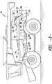
- FIG. 1 illustrates a simplified, side view of one embodiment of an agricultural combine 10.
- the combine 10 may be configured the same as or similar to any suitable agricultural combine known in the art.
- the combine 10 may include an axially arranged threshing system 12.
- the threshing system 12 may include a cylindrical rotor 14 rotatably supported within a cage or concave 16 for conveying a flow of crop material in a helical flow path along a circumferential space 18 defined between the rotor 14 and the concave 16.
- the crop e.g., grain, legumes, and/or the like
- the residue e.g., husks, pods and/or the like
- the crop residue may continue along the helical path and may be subsequently discharged through a discharge opening (not shown) defined at a downstream end 22 of the threshing system 12.
- the combine 10 may include a crop residue distribution system 24 for expelling the crop residue from the combine 10.
- the distribution system 24 may include a rotary device 26, such as a beater or a chopper, rotatably supported above a concave pan 28.
- the rotary device 26 may be configured to be rotated at a rapid speed such that the flow of crop residue exiting the threshing system 12 is propelled rearward along a series of internal shields or panels, such as a guide panel 30 (e.g., a strawhood frame or panel) and a windrow door 32, towards the rear end 34 of the combine 10.
- a guide panel 30 e.g., a strawhood frame or panel
- a windrow door 32 e.g., a windrow door
- the concave pan 28 may be angled in a manner such that the crop residue is propelled rearwardly and upwardly from the rotary device 26 into a distribution chamber 36 wherein the residue is directed along the guide panel 30 towards the windrow door 32 (indicated by arrows 38).
- the top end of the windrow door 32 may generally be configured to be rotatably or pivotally coupled to the guide panel 30.
- the windrow door 32 may be rotated relative to the guide panel 30 between a closed position (indicated by dashed lines 40), at which the crop residue flowing through the distribution chamber 36 is directed along the windrow door 32 and into a spreader 42 for swath spreading, and an opened position (indicated by dashed lines 44), at which the crop residue is directed along the windrow door and expelled through a rear opening 46 of the combine 10 for windrowing.
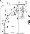
- the system 100 generally includes a spreader 102 configured to expel crop residue from the combine 10 and a windrow door 104 configured to direct the crop residue into the spreader 102 as it flows through the distribution chamber 36 at the rear end 34 of the combine 10.
- the spreader 102 may be configured the same as or similar to any suitable spreader known in the art.
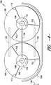
- the spreader 102 may be configured as a horizontal spreader and, thus, may include two horizontally oriented spreader discs (e.g., a first spreader disc 105 and a second spreader disc 106) configured to distribute crop residue sideways and rearwardly along a field.
- each spreader disc 105, 106 are configured to be rotated about an axis 108 extending generally perpendicular to the ground.
- the spreader 102 may also include a spreader cone 110 extending from the center of each spreader disc 105, 106 (e.g., by aligning the spreader cone 110 coaxially with the rotational axis 108) and a plurality of spreader paddles or tabs 112 extending radially outwardly from each spreader cone 110.
- the spreader 102 may have any other suitable configuration that permits it to function as described herein.
- crop residue is directed into the spreader 102 (e.g., via inlet 114) and onto the rotating spreader discs 105, 106.
- the spreader discs 105, 106 rotate, the crop residue is accelerated as it slides radially outwardly away from each spreader cone 110 and is subsequently discharged from the spreader 102 at the outer perimeter of each spreader disc 105, 106.
- the location at which the crop residue is introduced onto each spreader disc 105, 106 may significantly impact the velocity and the point of tangency at which the residue is expelled from the spreader 102, thereby affecting the spread distribution and/or spread width of the crop residue.
- the residue when the crop residue is introduced onto the spreader discs 105, 106 between the spreader cones 110 along a reference line 116 extending between the rotational axes 108 of the discs 105, 106 (i.e., central disc location 118 indicated by the solid box), the residue may be in contact with the spreader discs 105, 106 for a longer period of time prior to being expelled than if the crop residue was introduced onto the spreader discs 105, 106 at a location rearward of the reference line 116 (e.g., rear disc location 120 indicated by the dashed box).
- the crop residue may slide radially outwardly along the spreader discs 105, 106 a shorter distance before being expelled from the spreader 102, thereby reducing the velocity of the expelled crop residue.
- introducing the crop residue onto the spreader discs 105, 106 at a location forward of the reference line 116 may also impact the final velocity of the expelled crop residue. For example, as shown in FIG.
- the spreader 102 may include a side wall 124 extending along a forward portion of the spreader 102 to prevent crop residue from being expelled in the forward or travel direction of the combine 10 (indicated by arrow 126).
- the velocity of the crop residue that is eventually expelled from the rear of the spreader 102 may differ from the velocity achieved when the crop residue is introduced onto the spreader discs 105, 106 at the central disc location 118 or the rear disc location 120.
- the disclosed system 100 also includes a windrow door 104 configured to define a flow path for the crop residue traveling between the guide panel 30 and the spreader 102.
- a windrow door 104 configured to define a flow path for the crop residue traveling between the guide panel 30 and the spreader 102.
- at least a portion of the windrow door 104 may be configured to be moved relative to the spreader 102 so as to adjust the location at which the crop residue is introduced onto the spreader discs 105, 106.
- the flow of crop residue may be directed onto the spreader discs 105, 106 at the forward disc location 122, the central disc location 118, the rear disc location 120 or at any other suitable location along the spreader discs 105, 106.
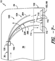
- the windrow door 104 includes a door panel 128 configured to serve as a guide for the crop residue as it flows past a downstream end 130 of the guide panel 30.
- the door panel 128 extends lengthwise between a first end 132 and a second end 134, with the first end 132 of the door panel 128 being coupled to the downstream end 130 of the guide panel 30.
- an inner surface 136 of the guide panel 30 and an inner surface 138 of the door panel 128 may generally define a substantially continuous flow path for the crop residue flowing within the distribution chamber 36 towards the rear end 34 of the combine 10.
- the door panel 128 may be configured to be rotatably coupled to the downstream end 130 of the guide panel 30. As such, the door panel 128 may be rotated relative to the guide panel 30 in order to alter the direction of flow of the crop residue between the spreader 102 and the rear opening 46 ( FIG. 1 ) of the combine 10. For instance, as shown in FIG. 2 , similar to the windrow door 32 described above with reference to FIG. 1 , the door panel 128 may be configured to be rotated to a closed position at which the curvature or tangential flow direction of the inner surface 138 of the door panel 128 at its second end 134 is directed towards the spreader 102.
- the crop residue may be directed along the inner surface 138 of the door panel 128 in the direction of the spreader 102.
- the door panel 128 may be moved to an opened position at which the second end 134 of the door panel 128 is rotated away from the spreader 102 so as to define the rear opening 46 ( FIG. 1 ) of the combine 10.
- the crop residue flowing along the windrow door 104 may be directed through the rear opening 46 and onto a field as a windrow.
- the windrow door 104 also includes a deflector panel 140 coupled to the second end 134 of the door panel 128.
- the deflector panel 140 generally forms an extension of the flow path for the crop residue traveling along the windrow door 104.
- the deflector panel 140 is configured to extend from the door panel 128 such that the crop residue flowing past the second end 134 of the door panel 128 is directed along an inner surface 142 of the deflector panel 140 and into the spreader 102.
- the inner surfaces 138, 142 of the panels 128, 140 may generally define a continuous flow path for the crop reside as it flows along the windrow door 104 between the guide panel 30 and the spreader 102.
- the deflector panel 140 is configured to be rotatably coupled to the second end 134 of the door panel 128 to allow the direction of flow of the crop residue to be altered as it enters the spreader 102.
- the deflector panel 140 is rotatably coupled to the door panel 128 via a hinge pin 144 or any other suitable hinged and/or or rotational attachment mechanism.
- the orientation of the deflector panel 140 relative to the door panel 128 and/or the spreader 102 may be adjusted in order to alter the trajectory of the crop residue flowing into the spreader 102.
- the deflector panel 140 may be initially positioned at a location relative to the door panel 128 and/or the spreader 102 so that the crop residue flowing along the inner surface 142 of the deflector panel 140 is directed onto the spreader discs 105, 106 at the central disc location 118 ( FIG. 4 ).
- the location at which crop residue is introduced onto the spreader discs 105, 106 may be adjusted. For instance, as shown FIGS.
- the deflector panel 140 may be rotated rearward relative to the door panel 128 to a rear deflector position (indicated by dashed lines 146) at which the flow of crop residue is directed along the inner surface 142 of the deflector panel 140 and onto the spreader discs 105, 106 at the rear residue location 120 ( FIG. 4 ).
- the deflector panel 140 may be rotated forward relative to the door panel 128 to a forward deflector position (indicated by dashed lines 148) at which the flow of crop residue is directed along the inner surface 142 of the deflector panel 140 and onto the spreader discs 105, 106 at the forward residue location 122 ( FIG. 4 ).
- the position of the deflector panel 140 relative to the door panel 128 and/or the spreader 102 may be configured to be manually adjusted.
- the position of the deflector panel 140 may be adjusted by means of a spring-loaded pin (not shown) and/or any other suitable manually adjustable positioning mechanism.
- an operator of the combine 10 may manually adjust the location of the spring-loaded pin and/or other positioning mechanism in order to move the deflector panel 140 relative to the door panel 128 and/or the spreader 102.
- the position of the deflector panel 140 may be configured to be automatically adjusted.
- a suitable electronically controllable actuating device may be operatively coupled to the deflector panel 140.
- an electric motor 150 may be coupled to the deflector panel 140 at the hinge axis defined between the deflector panel 140 and the door panel 128.
- the electric motor 150 may be coupled to a suitable controller to allow the operator to automatically adjust the position of the deflector panel 140 from within the operator's cab.
- any other suitable actuating device such as a linear actuator, hydraulic or pneumatic cylinder or a mechanical arrangement (e.g., a four bar linkage), may be used to automatically adjust the position of the deflector panels 140.
- such automatic control of the position of the deflector panel 140 may permit the operator of a combine 10 to make fine-tuned adjustments to the spread distribution and/or spread width of the crop residue as the combine 10 is being operated. For instance, if the current spread width of the crop residue is too narrow, the operator may automatically adjust the position of the deflector panel 140 relative to the door panel 128 and/or the spreader 102 in order to alter direction of the flow of the crop residue into the spreader 102 in a manner that increases the spread width.
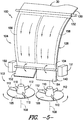
- the deflector panel 140 may comprise two or more deflector flaps 152, 154 extending outwardly from the door panel 128.
- the deflector panel 140 may include a first deflector flap 152 and a second deflector flap 154, with each deflector flap 152, 154 being rotatably coupled to the door panel 128.
- the deflector flaps 152, 154 may be configured to be independently rotated relative to the door panel 128 to allow for the direction of flow of the crop residue to be varied across the width of the deflector panel 140.
- the first deflector flap 152 may be configured to control the direction of flow of a left or first portion of the crop residue (indicated by the dashed box 156) as it is directed along the windrow door 104 and onto the first spreader disc 105.
- the second deflector flap 154 may be configured to control the direction of flow of a right or second portion of the crop residue (indicated by the dashed box 158) as it is directed along the windrow door 104 and onto the second spreader disc 106.
- the location at which the first portion 156 of the crop residue is introduced onto the first spreader disc 105 may be adjusted both radially along the first spreader disc 105 and relative to the location at which the second portion 158 of the crop residue is introduced into the second spreader disc 106 (indicated by the dashed box 162 in FIG. 6 ).
- each deflector flap 152, 154 may generally facilitate even further fine tuning of the spread distribution and/or spread width of the crop residue being expelled from the combine 10.
- the position of the second deflector flap 154 may be adjusted relative to the door panel 128 to alter the location at which the second portion 158 of the crop residue is introduced onto the second spreader disc 106.
- This may be particularly advantageous, for example, when a road or residential property is located adjacent to the farmland being harvested. In such case, the spread width of the crop residue being expelled along the side of the combine 10 on which the road or residential property is located may be reduced to ensure that the residue is not discharged into the path of a vehicle or onto a neighboring yard.
- a separate actuating device may be associated with each deflector flap 152, 154.
- a first electric motor 150 may be coupled to the first deflector flap 152 and a second electric motor 151 may be coupled to the second deflector flap 154.
- each motor 150, 151 may be separately controlled to adjust the position of each deflector flap 152, 154.
- the positions of the deflector flaps 152, 154 may be configured to be manually adjusted relative to the door panel 128 and/or relative to one another.
- FIG. 7 another embodiment of a windrow door 104 that may be utilized to control the location at which crop residue is introduced onto the spreader discs 105, 106 of the spreader 102 is illustrated in accordance with aspects of the present subject matter.
- the windrow door 104 may simply include a door panel 228 rotatably coupled to the downstream end 130 of the guide pane 30.
- the door panel 228 may be configured to be rotated relative to the guide panel 30 across a range of positions in order to adjust the direction of flow of the crop residue into the spreader 102.
- the door panel 228 may be configured to be positioned relative to the spreader 102 such that the flow of crop residue is generally directed between the spreader cones 110 of the spreader 102 (e.g., at the central disc location 118 shown in FIG. 4 ).
- the door panel 228 may be rotated rearward (indicated by the dashed lines 264) to direct the flow of crop residue towards the rear of the spreader disks 105, 106 (e.g. at the rear disc location 120 shown in FIG. 4 ) or the door panel 228 may be rotated forward (indicated by the dashed lines 266) to direct the flow of crop residue towards the front of the spreader disks 105, 106 (e.g. at the forward disc location 122 shown in FIG. 4 ).
- the position of the door panel 228 may be configured to be manually or automatically adjusted.
- a suitable actuating device such as an electric motor 150, may be coupled to the door panel 228 to allow the position of the panel 228 to be automatically adjusted.
- the door panel 228 may comprise two or more door flaps 268, 270 rotatably coupled to the guide panel 30.
- the door panel 228 may include a first door flap 268 and a second door flap 270, with each door flap 268, 270 being configured to be independently rotated relative to the guide panel 30.
- each door flap 268, 270 may be adjusted relative to guide panel 30 and/or relative to the other door flap 268, 270 in order to vary the direction of flow of the crop residue across the width of the door panel 228.
- the position of the first deflector flap 258 may be varied (e.g., via a first motor 150) to control the location at which the crop residue is introduced onto the first spreader disc 105 while the position of the second deflector flap 260 may be varied (e.g., via a second motor 151) to control the location at which the crop residue is introduced onto the second spreader disc 106.
- the windrow door 104 may be configured to be deflected to control the location at which the crop residue is introduced onto the spreader discs 105, 106.
- the windrow door 104 (or a portion thereof, such as the door panel 128, 228 or deflector panel 140) may be made of a lightweight, flexible material (e.g., a flexible plastic or other polymer material) that is capable of being flexed or deflected in order to adjust the shape and/or orientation of the windrow door 104 relative to the spreader 102.
- a suitable actuating device such as a linear actuator or cylinder, may be utilized to deflect the windrow door 104 relative to the spreader 102.
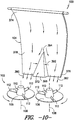
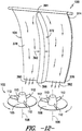
- the disclosed system 100 may also include a residue divider 372 configured to separate the flow of crop residue along the windrow door 104 into two or more separate residue flows.
- the windrow door 104 may generally be configured the same as or similar to any of the windrow door configurations described above with references to FIGS. 2-8 or the same as or similar to any conventional windrow door known in the art.
- the windrow door 104 may generally be configured to extend lengthwise between a first end 374 and a second end 376 and may include an inner surface 378 defining a generally continuously flow path for the crop residue flowing along the windrow door 104 between the guide panel 30 and the spreader 102.
- the residue divider 372 may generally be configured to project outwardly from the inner surface 378 of the windrow door 104 so as to separate the flow of crop residue directed along the inner surface 378 into a first a residue flow 380 and a second residue flow 380.
- Such division of the crop residue into separate flows may generally allow for the residue to be introduced onto the spreader discs 105, 106 at more focused locations, thereby providing for increased control of the spread distribution and/or spread width of the crop residue.
- the crop residue may be configured to be introduced onto the spreader discs 105, 106 at a central disc location (indicated by the dashed box 384) generally spanning the gap defined between the rotational axes 108 of the discs 105, 106.
- the residue may be directed onto specific areas of the spreader discs 105, 106. For example, as shown in FIG.
- the first residue flow 380 may be focused onto a location adjacent to the rotational axis 108 of the first spreader disk 105 (indicated by the box 386) and the second residue flow 382 may be focused onto a location adjacent to the rotational axis 108 of the second spreader disc 106 (indicated by box 388).
- the majority of the crop residue must slide radially outwardly along the discs 105, 106 a further distance prior to being expelled from the spreader 102, thereby increasing the velocity of the expelled crop residue.
- the residue divider 372 may be utilized to direct the crop residue onto any other suitable locations along the spreader discs 105, 106. For instance, by adjusting the location of the windrow door 104 relative to the spreader 102, the first and second residue flows 380, 382 may be directed onto radially outer portions of the spreader discs 105, 106 (indicated by the dashed boxes 390), thereby resulting in a decrease in the velocity of the expelled crop residue. Similarly, by adjusting the position of the residue divider 372 along the length of the windrow door 104, a split distance 389 ( FIG. 11 ) defined between the residue flows 380, 382 may be increased or decreased. For example, by moving the position of the residue divider 372 shown in FIGS. 9 and 10 to a location closer to the first end 374 of the windrow door 104, the split distance 389 defined between the residue flows 380, 382 may be increased.
- the residue divider 372 may generally have any suitable configuration that permits it to function as described herein.
- the residue divider 372 may be wedge or pyramid- shaped and, thus, may define a diverging width 392.
- the residue divider 372 may be configured to extend lengthwise between an upstream end 394 and a downstream end 396, with the width 392 of the divider 372 diverging between the upstream and downstream ends 392, 396.
- the residue divider 372 may be configured to define a relatively constant width 392 between its upstream and downstream ends 394, 396.
- the residue divider 372 may be configured to extend lengthwise any suitable distance between the first and second ends 374, 376 of the windrow door 104.
- the divider 372 may extend only partially between the first and second ends 374, 376 of the windrow door 104.
- the divider 372 may be configured to extend fully between the first and second ends 374, 376 of the windrow door 104.
Landscapes
- Life Sciences & Earth Sciences (AREA)
- Environmental Sciences (AREA)
- Harvester Elements (AREA)
- Fertilizing (AREA)
- Catching Or Destruction (AREA)
- Harvesting Machines For Root Crops (AREA)
Claims (9)
- Anordnung (100) zur Steuerung der Verteilung von Ernterückständen, die von einem landwirtschaftlichen Mähdrescher (10) ausgestoßen werden, wobei die Anordnung umfasst:eine Streueinrichtung (102), die dazu eingerichtet ist, Ernterückstände aus dem Mähdrescher (10) auszustoßen, wobei die Streueinrichtung (102) eine Streuscheibe (105, 106) umfasst, die dazu eingerichtet ist, um eine Achse (108) gedreht zu werden;eine Schwadklappe (32, 104), die eine innere Oberfläche (136, 138, 142) umfasst, die eine Strömungsbahn zum Leiten der Ernterückstände in die Streueinrichtung (102) definiert,wobei zumindest ein Abschnitt (140, 152, 154) der Schwadklappe (32, 104) dazu eingerichtet ist, relativ zur Streueinrichtung (102) bewegt zu werden, um eine Stelle einzustellen, an der die Ernterückstände der Streuscheibe (105, 106) zugeführt werden, wobei die Schwadklappe (32, 104) eine Klappenplatte (128, 228) umfasst, die sich der Länge nach zwischen einem ersten Ende (132) und einem zweiten Ende (134) erstreckt, wobei die Anordnung dadurch gekennzeichnet ist, dass die Schwadklappe (32, 104) weiterhin eine Umlenkplatte (140, 152, 154) umfasst, die drehbar mit dem zweiten Ende der Klappenplatte (128, 228) verbunden ist, um eine Verlängerung der Strömungsbahn zu bilden, die durch die innere Oberfläche (136, 138, 142) der Schwadklappe (32, 104) definiert ist, wobei die Umlenkplatte (140, 152, 154) dazu eingerichtet ist, relativ zur Klappenplatte (128, 228) gedreht zu werden, um die Stelle einzustellen, an der die Ernterückstände der Streuscheibe (105, 106) zugeführt werden.
- Anordnung nach Anspruch 1, wobei die Umlenkplatte (140, 152, 154) der Schwadklappe (32, 104) dazu eingerichtet ist, relativ zur Streueinrichtung (102) derart bewegt zu werden, dass die Stelle, an der die Ernterückstände der Streuscheibe (105, 106) zugeführt werden, radial außerhalb der Achse (108) eingestellt wird.
- Anordnung nach Anspruch 1, weiterhin mit einer Betätigungsvorrichtung (150), die mit der Umlenkplatte (140, 152, 154) verbunden ist, wobei die Betätigungsvorrichtung dazu eingerichtet ist, die Umlenkplatte (140, 152, 154) relativ zur Klappenplatte (128, 228) zu bewegen.
- Anordnung nach Anspruch 1, wobei die Umlenkplatte (140, 152, 154) einen ersten Umlenkflügel (152) und einen zweiten Umlenkflügel (154) umfasst.
- Anordnung nach Anspruch 4, wobei der erste Umlenkflügel (152) dazu eingerichtet ist, unabhängig vom zweiten Umlenkflügel (154) relativ zur Klappenplatte (128, 228) bewegt zu werden.
- Anordnung nach Anspruch 1, wobei die Klappenplatte (128, 228) mit einer Führungsplatte (30) des Mähdreschers (10) verbunden ist, wobei die Klappenplatte (128, 228) dazu eingerichtet ist, relativ zu der Führungsplatte (30) bewegt zu werden, um die Stelle einzustellen, an der die Ernterückstände der Streuscheibe (105, 106) zugeführt werden.
- Anordnung nach Anspruch 6, wobei die Klappenplatte (128, 228) einen ersten Klappenflügel (268) und einen zweiten Klappenflügel (270) umfasst.
- Anordnung nach Anspruch 7, wobei der erste Klappenflügel (268) dazu eingerichtet ist, unabhängig vom zweiten Klappenflügel (270) relativ zur Führungsplatte (30) bewegt zu werden.
- Anordnung nach Anspruch 1, weiterhin mit einer Rückstandstrenneinrichtung (372), die sich von der inneren Oberfläche (136, 138, 142) der Schwadklappe (32, 104) erstreckt, wobei die Rückstandstrenneinrichtung dazu eingerichtet ist, die Ernterückstände, die entlang der inneren Oberfläche (136, 138, 142) strömen, in zumindest zwei getrennte Rückstandsströme zu teilen.
Applications Claiming Priority (2)
| Application Number | Priority Date | Filing Date | Title |
|---|---|---|---|
| US13/600,758 US9107349B2 (en) | 2012-08-31 | 2012-08-31 | System and method for controlling the spreading of crop residue expelled from an agricultural combine |
| PCT/US2013/056413 WO2014035825A2 (en) | 2012-08-31 | 2013-08-23 | System and method for controlling the spreading of crop residue expelled from an agricultural combine |
Publications (2)
| Publication Number | Publication Date |
|---|---|
| EP2890239A2 EP2890239A2 (de) | 2015-07-08 |
| EP2890239B1 true EP2890239B1 (de) | 2019-06-12 |
Family
ID=49123909
Family Applications (1)
| Application Number | Title | Priority Date | Filing Date |
|---|---|---|---|
| EP13759616.9A Active EP2890239B1 (de) | 2012-08-31 | 2013-08-23 | System zur steuerung der ausbreitung von ernteresten aus einem mähdrescher |
Country Status (5)
| Country | Link |
|---|---|
| US (1) | US9107349B2 (de) |
| EP (1) | EP2890239B1 (de) |
| CN (1) | CN104936431B (de) |
| BR (1) | BR112015004627B1 (de) |
| WO (1) | WO2014035825A2 (de) |
Families Citing this family (23)
| Publication number | Priority date | Publication date | Assignee | Title |
|---|---|---|---|---|
| US20150264864A1 (en) | 2014-03-20 | 2015-09-24 | Deere & Company | Mog sensing system for a residue spreader |
| DE102015004325B3 (de) * | 2015-04-09 | 2016-05-19 | B. Strautmann & Söhne GmbH u. Co. KG | Landwirtschaftlicher Erntewagen mit Dosiergerät und Breitverteilung |
| US9801340B2 (en) * | 2015-04-30 | 2017-10-31 | Cnh Industrial America Llc | Spreader arrangement for an agricultural harvester |
| US10188034B2 (en) * | 2015-10-05 | 2019-01-29 | Cnh Industrial America Llc | Material guide for a straw hood of an agricultural vehicle |
| US10952374B2 (en) * | 2017-05-01 | 2021-03-23 | Cnh Industrial America Llc | System and method for monitoring residue output from a harvester |
| US10537062B2 (en) | 2017-05-26 | 2020-01-21 | Cnh Industrial America Llc | Aerial vehicle systems and methods |
| US10314232B2 (en) | 2017-06-21 | 2019-06-11 | Cnh Industrial America Llc | System and method for destroying seeds in crop residue prior to discharge from agricultural harvester |
| US10952373B2 (en) * | 2017-08-29 | 2021-03-23 | Deere & Company | Straw deflector for an agricultural combine |
| US10485170B2 (en) * | 2017-09-20 | 2019-11-26 | Cnh Industrial America Llc | Debris removal system for an agricultural harvester and related extractors |
| US10648210B1 (en) * | 2017-09-26 | 2020-05-12 | Apple Inc. | Multi-linkage vehicle door hinge |
| DE102017222409B4 (de) * | 2017-12-11 | 2026-05-13 | Deere & Company | Anordnung zum Umschalten eines Mähdreschers zum Wechsel zwischen Schwadablage- und Breitverteilbetrieb |
| CN108093830A (zh) * | 2017-12-12 | 2018-06-01 | 农业部南京农业机械化研究所 | 一种颖糠双抛洒轮机构 |
| US11019768B2 (en) * | 2018-02-26 | 2021-06-01 | Deere & Company | Double decker crop residue spreader |
| US11865570B2 (en) * | 2018-11-22 | 2024-01-09 | Salford Group Inc. | Flow divider for spinner spreader |
| DE102019107840A1 (de) * | 2019-03-27 | 2020-10-01 | Claas Selbstfahrende Erntemaschinen Gmbh | Verfahren zum Betrieb eines Mähdreschers sowie selbstfahrender Mähdrescher |
| US11997946B2 (en) | 2019-04-25 | 2024-06-04 | Deere & Company | Access door with integral crop deflector for a combine harvester and method of manufacturing the same |
| CN112119752B (zh) * | 2019-06-24 | 2024-06-28 | 迪尔公司 | 具有分离帘幕的堆料系统及其方法 |
| DE102019126405A1 (de) * | 2019-09-30 | 2021-04-01 | Claas Selbstfahrende Erntemaschinen Gmbh | Verteileinrichtung für Häckselgut |
| AR126331A1 (es) | 2021-04-28 | 2023-10-04 | Cnh Ind America Llc | Panel móvil para sortear la cortadora de un vehículo agrícola |
| US12004447B2 (en) * | 2021-10-01 | 2024-06-11 | Cnh Industrial America Llc | Pivotable windrow chute for combine harvester |
| EP4173466B1 (de) * | 2021-11-02 | 2024-08-21 | CNH Industrial Belgium N.V. | Einstellbares streusystem für eine landwirtschaftliche erntemaschine |
| GB202218828D0 (en) * | 2022-12-14 | 2023-01-25 | Agco Int Gmbh | Residue chopper and spreader arrangement |
| GB202219841D0 (en) * | 2022-12-30 | 2023-02-15 | Agco Int Gmbh | Crop residue spreader arrangement |
Citations (1)
| Publication number | Priority date | Publication date | Assignee | Title |
|---|---|---|---|---|
| US20040242291A1 (en) * | 2003-01-30 | 2004-12-02 | Dirk Weichholdt | Combine with straw chopper |
Family Cites Families (27)
| Publication number | Priority date | Publication date | Assignee | Title |
|---|---|---|---|---|
| US4056107A (en) | 1976-04-26 | 1977-11-01 | Sperry Rand Corporation | Crop residue deflector means |
| US4263772A (en) | 1980-03-10 | 1981-04-28 | Sperry Corporation | Pivotable forage harvester transfer chute |
| GB8305259D0 (en) | 1983-02-25 | 1983-03-30 | Sperry Nv | Combine harvesters |
| CN2083401U (zh) * | 1990-11-15 | 1991-08-28 | 上海市农场管理局农业机械研究所 | 一种秸秆抛撒装置 |
| DE4431802A1 (de) | 1994-09-07 | 1996-03-14 | Claas Ohg | Anbauhäcksler mit Breitverteileraustrag für zu zerkleinerndes Gut, insbesondere Stroh/Spreu-Gemisch für/an einem Mähdrescher |
| DE10130652A1 (de) | 2001-06-27 | 2003-01-30 | Claas Selbstfahr Erntemasch | Mähdrescher mit Wurfgebläse |
| US6719627B2 (en) | 2001-12-17 | 2004-04-13 | Case Corporation | Multi-position linkage and locking mechanism for a crop residue spreader and/or chopper |
| DE10215026A1 (de) | 2002-04-05 | 2003-11-06 | Deere & Co | Mähdrescher mit motorisch verstellbarer Strohleiteinrichtung |
| DE10219895A1 (de) * | 2002-05-03 | 2003-12-24 | Deere & Co | Mähdrescher mit Strohhäcksler |
| US6547169B1 (en) | 2002-06-25 | 2003-04-15 | Case Corporation | Crop residue spreader for an agricultural combine |
| GB0305253D0 (en) | 2003-03-07 | 2003-04-09 | Cnh Belgium Nv | Combine harvester |
| US7066810B2 (en) * | 2003-11-07 | 2006-06-27 | Cnh America Llc | System and method for positively discharging crop residue from a combine |
| US6893340B1 (en) * | 2003-12-09 | 2005-05-17 | Cnh America Llc | Rotary accelerating apparatus for a vertical straw and chaff spreader of an agricultural combine |
| CA2470876C (en) * | 2004-06-14 | 2009-12-08 | Redekop Chaff Systems Ltd. | Combine harvester with ready adjustment of discharge positions of straw and chaff |
| US7186179B1 (en) | 2005-08-15 | 2007-03-06 | Cnh America Llc | Adjustable flow deflector apparatus for transitioning crop residue flow from an axially arranged threshing system to a residue distribution system of an agricultural combine |
| US7473169B2 (en) * | 2007-02-28 | 2009-01-06 | Cnh America Llc | Adjustable axial rotor discharge deflector |
| US7648413B2 (en) * | 2007-03-01 | 2010-01-19 | Cnh America Llc | Combine harvester power management control |
| US7487024B2 (en) | 2007-04-26 | 2009-02-03 | Cnh America Llc | Apparatus and method for automatically setting operating parameters for a remotely adjustable spreader of an agricultural harvesting machine |
| US7559833B2 (en) * | 2007-06-29 | 2009-07-14 | Cnh America Llc | Adjustable convergence panels for discharging residue from a combine harvester |
| US7635299B2 (en) | 2007-09-28 | 2009-12-22 | Cnh America Llc | Windrow forming construction |
| US7896732B2 (en) * | 2007-12-13 | 2011-03-01 | CNH America | Crop residue chopping and spreading system for an agricultural combine |
| EP2138024B1 (de) | 2008-06-25 | 2011-08-17 | CNH Belgium N.V. | Angetriebener Streuer für einen Mähdrescher |
| EP2279654B1 (de) | 2009-07-28 | 2015-05-20 | CNH Industrial Belgium nv | Zur Spreizscheibenanordnung umwandelbare Steinschwadeanordnung |
| US8010262B2 (en) | 2009-10-21 | 2011-08-30 | Cnh America Llc | Apparatus and method for automatically controlling the settings of an adjustable crop residue spreader of an agricultural combine |
| BE1019133A3 (nl) * | 2010-01-05 | 2012-03-06 | Cnh Belgium Nv | Een maaidorser. |
| CN201766860U (zh) * | 2010-03-24 | 2011-03-23 | 镇江市万金农机有限公司 | 一种秸秆抛撒风机 |
| US8585475B2 (en) * | 2011-04-19 | 2013-11-19 | Cnh America Llc | Crop residue distribution apparatus and system with cooperatively movable deflector door and spreader assembly |
-
2012
- 2012-08-31 US US13/600,758 patent/US9107349B2/en active Active
-
2013
- 2013-08-23 WO PCT/US2013/056413 patent/WO2014035825A2/en not_active Ceased
- 2013-08-23 EP EP13759616.9A patent/EP2890239B1/de active Active
- 2013-08-23 CN CN201380053719.5A patent/CN104936431B/zh active Active
- 2013-08-23 BR BR112015004627-4A patent/BR112015004627B1/pt active IP Right Grant
Patent Citations (1)
| Publication number | Priority date | Publication date | Assignee | Title |
|---|---|---|---|---|
| US20040242291A1 (en) * | 2003-01-30 | 2004-12-02 | Dirk Weichholdt | Combine with straw chopper |
Also Published As
| Publication number | Publication date |
|---|---|
| CN104936431B (zh) | 2019-01-18 |
| CN104936431A (zh) | 2015-09-23 |
| US20140066148A1 (en) | 2014-03-06 |
| WO2014035825A3 (en) | 2014-04-24 |
| WO2014035825A2 (en) | 2014-03-06 |
| BR112015004627B1 (pt) | 2020-07-14 |
| EP2890239A2 (de) | 2015-07-08 |
| BR112015004627A2 (pt) | 2017-07-04 |
| US9107349B2 (en) | 2015-08-18 |
Similar Documents
| Publication | Publication Date | Title |
|---|---|---|
| US9107349B2 (en) | System and method for controlling the spreading of crop residue expelled from an agricultural combine | |
| EP2890235B1 (de) | Schwadentüranordnung für einen mähdrescher | |
| US6736721B2 (en) | Stalk and chaff distribution arrangement | |
| EP2702853B1 (de) | Schwadentür für einen landwirtschaftlichen Mähdrescher | |
| US6840853B2 (en) | Distributing device having continuously moving guide vanes | |
| EP2138024B1 (de) | Angetriebener Streuer für einen Mähdrescher | |
| US7717779B1 (en) | Combine with a conveyor switchable between swath deposit operation and chopper operation in different directions of rotation | |
| US8079900B2 (en) | Harvester with an additional drum conveyor for straw removal and a single flap for changing between swath deposit and chopping operation | |
| EP3409095B1 (de) | Landwirtschaftlicher mähdrescher mit umkehrhäckslerrotor | |
| US20090111549A1 (en) | Combine harvester residue chopper active counter knife assembly | |
| US12495732B2 (en) | Adjustable spreader system for an agricultural harvester | |
| EP3153001B1 (de) | Materialführung für eine strohhaube eines landwirtschaftlichen fahrzeugs | |
| EP2993968B1 (de) | Häcksler/gebläsanordnung für einen vorsatz einer landwirtschaftlichen erntemaschine | |
| US10398081B2 (en) | Straw spreader and chaff spreader for a combine harvester | |
| AU2022236291A9 (en) | Straw processing system | |
| AU2023200889B2 (en) | Weed seed destruction on a combine harvester |
Legal Events
| Date | Code | Title | Description |
|---|---|---|---|
| PUAI | Public reference made under article 153(3) epc to a published international application that has entered the european phase |
Free format text: ORIGINAL CODE: 0009012 |
|
| 17P | Request for examination filed |
Effective date: 20150331 |
|
| AK | Designated contracting states |
Kind code of ref document: A2 Designated state(s): AL AT BE BG CH CY CZ DE DK EE ES FI FR GB GR HR HU IE IS IT LI LT LU LV MC MK MT NL NO PL PT RO RS SE SI SK SM TR |
|
| AX | Request for extension of the european patent |
Extension state: BA ME |
|
| RAP1 | Party data changed (applicant data changed or rights of an application transferred) |
Owner name: CNH INDUSTRIAL BELGIUM N.V. |
|
| DAX | Request for extension of the european patent (deleted) | ||
| STAA | Information on the status of an ep patent application or granted ep patent |
Free format text: STATUS: EXAMINATION IS IN PROGRESS |
|
| 17Q | First examination report despatched |
Effective date: 20180430 |
|
| GRAP | Despatch of communication of intention to grant a patent |
Free format text: ORIGINAL CODE: EPIDOSNIGR1 |
|
| STAA | Information on the status of an ep patent application or granted ep patent |
Free format text: STATUS: GRANT OF PATENT IS INTENDED |
|
| INTG | Intention to grant announced |
Effective date: 20181221 |
|
| RIN1 | Information on inventor provided before grant (corrected) |
Inventor name: DILTS, MARK DAVID Inventor name: ISAAC, NATHAN E. |
|
| INTG | Intention to grant announced |
Effective date: 20190103 |
|
| GRAS | Grant fee paid |
Free format text: ORIGINAL CODE: EPIDOSNIGR3 |
|
| GRAA | (expected) grant |
Free format text: ORIGINAL CODE: 0009210 |
|
| STAA | Information on the status of an ep patent application or granted ep patent |
Free format text: STATUS: THE PATENT HAS BEEN GRANTED |
|
| AK | Designated contracting states |
Kind code of ref document: B1 Designated state(s): AL AT BE BG CH CY CZ DE DK EE ES FI FR GB GR HR HU IE IS IT LI LT LU LV MC MK MT NL NO PL PT RO RS SE SI SK SM TR |
|
| REG | Reference to a national code |
Ref country code: GB Ref legal event code: FG4D |
|
| REG | Reference to a national code |
Ref country code: CH Ref legal event code: EP |
|
| REG | Reference to a national code |
Ref country code: AT Ref legal event code: REF Ref document number: 1141335 Country of ref document: AT Kind code of ref document: T Effective date: 20190615 |
|
| REG | Reference to a national code |
Ref country code: DE Ref legal event code: R096 Ref document number: 602013056538 Country of ref document: DE |
|
| REG | Reference to a national code |
Ref country code: IE Ref legal event code: FG4D |
|
| REG | Reference to a national code |
Ref country code: NL Ref legal event code: MP Effective date: 20190612 |
|
| REG | Reference to a national code |
Ref country code: LT Ref legal event code: MG4D |
|
| PG25 | Lapsed in a contracting state [announced via postgrant information from national office to epo] |
Ref country code: AL Free format text: LAPSE BECAUSE OF FAILURE TO SUBMIT A TRANSLATION OF THE DESCRIPTION OR TO PAY THE FEE WITHIN THE PRESCRIBED TIME-LIMIT Effective date: 20190612 Ref country code: SE Free format text: LAPSE BECAUSE OF FAILURE TO SUBMIT A TRANSLATION OF THE DESCRIPTION OR TO PAY THE FEE WITHIN THE PRESCRIBED TIME-LIMIT Effective date: 20190612 Ref country code: HR Free format text: LAPSE BECAUSE OF FAILURE TO SUBMIT A TRANSLATION OF THE DESCRIPTION OR TO PAY THE FEE WITHIN THE PRESCRIBED TIME-LIMIT Effective date: 20190612 Ref country code: NO Free format text: LAPSE BECAUSE OF FAILURE TO SUBMIT A TRANSLATION OF THE DESCRIPTION OR TO PAY THE FEE WITHIN THE PRESCRIBED TIME-LIMIT Effective date: 20190912 Ref country code: FI Free format text: LAPSE BECAUSE OF FAILURE TO SUBMIT A TRANSLATION OF THE DESCRIPTION OR TO PAY THE FEE WITHIN THE PRESCRIBED TIME-LIMIT Effective date: 20190612 Ref country code: LT Free format text: LAPSE BECAUSE OF FAILURE TO SUBMIT A TRANSLATION OF THE DESCRIPTION OR TO PAY THE FEE WITHIN THE PRESCRIBED TIME-LIMIT Effective date: 20190612 |
|
| PG25 | Lapsed in a contracting state [announced via postgrant information from national office to epo] |
Ref country code: RS Free format text: LAPSE BECAUSE OF FAILURE TO SUBMIT A TRANSLATION OF THE DESCRIPTION OR TO PAY THE FEE WITHIN THE PRESCRIBED TIME-LIMIT Effective date: 20190612 Ref country code: LV Free format text: LAPSE BECAUSE OF FAILURE TO SUBMIT A TRANSLATION OF THE DESCRIPTION OR TO PAY THE FEE WITHIN THE PRESCRIBED TIME-LIMIT Effective date: 20190612 Ref country code: BG Free format text: LAPSE BECAUSE OF FAILURE TO SUBMIT A TRANSLATION OF THE DESCRIPTION OR TO PAY THE FEE WITHIN THE PRESCRIBED TIME-LIMIT Effective date: 20190912 Ref country code: GR Free format text: LAPSE BECAUSE OF FAILURE TO SUBMIT A TRANSLATION OF THE DESCRIPTION OR TO PAY THE FEE WITHIN THE PRESCRIBED TIME-LIMIT Effective date: 20190913 |
|
| REG | Reference to a national code |
Ref country code: AT Ref legal event code: MK05 Ref document number: 1141335 Country of ref document: AT Kind code of ref document: T Effective date: 20190612 |
|
| PG25 | Lapsed in a contracting state [announced via postgrant information from national office to epo] |
Ref country code: PT Free format text: LAPSE BECAUSE OF FAILURE TO SUBMIT A TRANSLATION OF THE DESCRIPTION OR TO PAY THE FEE WITHIN THE PRESCRIBED TIME-LIMIT Effective date: 20191014 Ref country code: SK Free format text: LAPSE BECAUSE OF FAILURE TO SUBMIT A TRANSLATION OF THE DESCRIPTION OR TO PAY THE FEE WITHIN THE PRESCRIBED TIME-LIMIT Effective date: 20190612 Ref country code: EE Free format text: LAPSE BECAUSE OF FAILURE TO SUBMIT A TRANSLATION OF THE DESCRIPTION OR TO PAY THE FEE WITHIN THE PRESCRIBED TIME-LIMIT Effective date: 20190612 Ref country code: CZ Free format text: LAPSE BECAUSE OF FAILURE TO SUBMIT A TRANSLATION OF THE DESCRIPTION OR TO PAY THE FEE WITHIN THE PRESCRIBED TIME-LIMIT Effective date: 20190612 Ref country code: AT Free format text: LAPSE BECAUSE OF FAILURE TO SUBMIT A TRANSLATION OF THE DESCRIPTION OR TO PAY THE FEE WITHIN THE PRESCRIBED TIME-LIMIT Effective date: 20190612 Ref country code: NL Free format text: LAPSE BECAUSE OF FAILURE TO SUBMIT A TRANSLATION OF THE DESCRIPTION OR TO PAY THE FEE WITHIN THE PRESCRIBED TIME-LIMIT Effective date: 20190612 Ref country code: RO Free format text: LAPSE BECAUSE OF FAILURE TO SUBMIT A TRANSLATION OF THE DESCRIPTION OR TO PAY THE FEE WITHIN THE PRESCRIBED TIME-LIMIT Effective date: 20190612 |
|
| PG25 | Lapsed in a contracting state [announced via postgrant information from national office to epo] |
Ref country code: ES Free format text: LAPSE BECAUSE OF FAILURE TO SUBMIT A TRANSLATION OF THE DESCRIPTION OR TO PAY THE FEE WITHIN THE PRESCRIBED TIME-LIMIT Effective date: 20190612 Ref country code: SM Free format text: LAPSE BECAUSE OF FAILURE TO SUBMIT A TRANSLATION OF THE DESCRIPTION OR TO PAY THE FEE WITHIN THE PRESCRIBED TIME-LIMIT Effective date: 20190612 Ref country code: IS Free format text: LAPSE BECAUSE OF FAILURE TO SUBMIT A TRANSLATION OF THE DESCRIPTION OR TO PAY THE FEE WITHIN THE PRESCRIBED TIME-LIMIT Effective date: 20191012 |
|
| REG | Reference to a national code |
Ref country code: DE Ref legal event code: R097 Ref document number: 602013056538 Country of ref document: DE |
|
| PG25 | Lapsed in a contracting state [announced via postgrant information from national office to epo] |
Ref country code: TR Free format text: LAPSE BECAUSE OF FAILURE TO SUBMIT A TRANSLATION OF THE DESCRIPTION OR TO PAY THE FEE WITHIN THE PRESCRIBED TIME-LIMIT Effective date: 20190612 |
|
| PLBE | No opposition filed within time limit |
Free format text: ORIGINAL CODE: 0009261 |
|
| STAA | Information on the status of an ep patent application or granted ep patent |
Free format text: STATUS: NO OPPOSITION FILED WITHIN TIME LIMIT |
|
| PG25 | Lapsed in a contracting state [announced via postgrant information from national office to epo] |
Ref country code: PL Free format text: LAPSE BECAUSE OF FAILURE TO SUBMIT A TRANSLATION OF THE DESCRIPTION OR TO PAY THE FEE WITHIN THE PRESCRIBED TIME-LIMIT Effective date: 20190612 Ref country code: DK Free format text: LAPSE BECAUSE OF FAILURE TO SUBMIT A TRANSLATION OF THE DESCRIPTION OR TO PAY THE FEE WITHIN THE PRESCRIBED TIME-LIMIT Effective date: 20190612 |
|
| 26N | No opposition filed |
Effective date: 20200313 |
|
| PG25 | Lapsed in a contracting state [announced via postgrant information from national office to epo] |
Ref country code: MC Free format text: LAPSE BECAUSE OF FAILURE TO SUBMIT A TRANSLATION OF THE DESCRIPTION OR TO PAY THE FEE WITHIN THE PRESCRIBED TIME-LIMIT Effective date: 20190612 Ref country code: CH Free format text: LAPSE BECAUSE OF NON-PAYMENT OF DUE FEES Effective date: 20190831 Ref country code: LI Free format text: LAPSE BECAUSE OF NON-PAYMENT OF DUE FEES Effective date: 20190831 Ref country code: IS Free format text: LAPSE BECAUSE OF FAILURE TO SUBMIT A TRANSLATION OF THE DESCRIPTION OR TO PAY THE FEE WITHIN THE PRESCRIBED TIME-LIMIT Effective date: 20200224 Ref country code: LU Free format text: LAPSE BECAUSE OF NON-PAYMENT OF DUE FEES Effective date: 20190823 Ref country code: SI Free format text: LAPSE BECAUSE OF FAILURE TO SUBMIT A TRANSLATION OF THE DESCRIPTION OR TO PAY THE FEE WITHIN THE PRESCRIBED TIME-LIMIT Effective date: 20190612 |
|
| REG | Reference to a national code |
Ref country code: BE Ref legal event code: MM Effective date: 20190831 |
|
| PG2D | Information on lapse in contracting state deleted |
Ref country code: IS |
|
| PG25 | Lapsed in a contracting state [announced via postgrant information from national office to epo] |
Ref country code: IE Free format text: LAPSE BECAUSE OF NON-PAYMENT OF DUE FEES Effective date: 20190823 |
|
| PG25 | Lapsed in a contracting state [announced via postgrant information from national office to epo] |
Ref country code: BE Free format text: LAPSE BECAUSE OF NON-PAYMENT OF DUE FEES Effective date: 20190831 |
|
| PG25 | Lapsed in a contracting state [announced via postgrant information from national office to epo] |
Ref country code: CY Free format text: LAPSE BECAUSE OF FAILURE TO SUBMIT A TRANSLATION OF THE DESCRIPTION OR TO PAY THE FEE WITHIN THE PRESCRIBED TIME-LIMIT Effective date: 20190612 |
|
| PG25 | Lapsed in a contracting state [announced via postgrant information from national office to epo] |
Ref country code: MT Free format text: LAPSE BECAUSE OF FAILURE TO SUBMIT A TRANSLATION OF THE DESCRIPTION OR TO PAY THE FEE WITHIN THE PRESCRIBED TIME-LIMIT Effective date: 20190612 Ref country code: HU Free format text: LAPSE BECAUSE OF FAILURE TO SUBMIT A TRANSLATION OF THE DESCRIPTION OR TO PAY THE FEE WITHIN THE PRESCRIBED TIME-LIMIT; INVALID AB INITIO Effective date: 20130823 |
|
| PG25 | Lapsed in a contracting state [announced via postgrant information from national office to epo] |
Ref country code: MK Free format text: LAPSE BECAUSE OF FAILURE TO SUBMIT A TRANSLATION OF THE DESCRIPTION OR TO PAY THE FEE WITHIN THE PRESCRIBED TIME-LIMIT Effective date: 20190612 |
|
| REG | Reference to a national code |
Ref country code: GB Ref legal event code: 746 Effective date: 20240726 |
|
| PGFP | Annual fee paid to national office [announced via postgrant information from national office to epo] |
Ref country code: DE Payment date: 20250827 Year of fee payment: 13 |
|
| PGFP | Annual fee paid to national office [announced via postgrant information from national office to epo] |
Ref country code: IT Payment date: 20250825 Year of fee payment: 13 |
|
| PGFP | Annual fee paid to national office [announced via postgrant information from national office to epo] |
Ref country code: GB Payment date: 20250826 Year of fee payment: 13 |
|
| PGFP | Annual fee paid to national office [announced via postgrant information from national office to epo] |
Ref country code: FR Payment date: 20250825 Year of fee payment: 13 |