EP2890002A2 - Method for controlling inverter - Google Patents
Method for controlling inverter Download PDFInfo
- Publication number
- EP2890002A2 EP2890002A2 EP14177265.7A EP14177265A EP2890002A2 EP 2890002 A2 EP2890002 A2 EP 2890002A2 EP 14177265 A EP14177265 A EP 14177265A EP 2890002 A2 EP2890002 A2 EP 2890002A2
- Authority
- EP
- European Patent Office
- Prior art keywords
- pid
- soft fill
- set value
- inverter
- present disclosure
- Prior art date
- Legal status (The legal status is an assumption and is not a legal conclusion. Google has not performed a legal analysis and makes no representation as to the accuracy of the status listed.)
- Granted
Links
Images



Classifications
-
- G—PHYSICS
- G05—CONTROLLING; REGULATING
- G05B—CONTROL OR REGULATING SYSTEMS IN GENERAL; FUNCTIONAL ELEMENTS OF SUCH SYSTEMS; MONITORING OR TESTING ARRANGEMENTS FOR SUCH SYSTEMS OR ELEMENTS
- G05B11/00—Automatic controllers
- G05B11/01—Automatic controllers electric
- G05B11/36—Automatic controllers electric with provision for obtaining particular characteristics, e.g. proportional, integral, differential
-
- H—ELECTRICITY
- H02—GENERATION; CONVERSION OR DISTRIBUTION OF ELECTRIC POWER
- H02M—APPARATUS FOR CONVERSION BETWEEN AC AND AC, BETWEEN AC AND DC, OR BETWEEN DC AND DC, AND FOR USE WITH MAINS OR SIMILAR POWER SUPPLY SYSTEMS; CONVERSION OF DC OR AC INPUT POWER INTO SURGE OUTPUT POWER; CONTROL OR REGULATION THEREOF
- H02M7/00—Conversion of AC power input into DC power output; Conversion of DC power input into AC power output
- H02M7/42—Conversion of DC power input into AC power output without possibility of reversal
- H02M7/44—Conversion of DC power input into AC power output without possibility of reversal by static converters
- H02M7/48—Conversion of DC power input into AC power output without possibility of reversal by static converters using discharge tubes with control electrode or semiconductor devices with control electrode
-
- F—MECHANICAL ENGINEERING; LIGHTING; HEATING; WEAPONS; BLASTING
- F04—POSITIVE - DISPLACEMENT MACHINES FOR LIQUIDS; PUMPS FOR LIQUIDS OR ELASTIC FLUIDS
- F04B—POSITIVE-DISPLACEMENT MACHINES FOR LIQUIDS; PUMPS
- F04B17/00—Pumps characterised by combination with, or adaptation to, specific driving engines or motors
- F04B17/03—Pumps characterised by combination with, or adaptation to, specific driving engines or motors driven by electric motors
-
- F—MECHANICAL ENGINEERING; LIGHTING; HEATING; WEAPONS; BLASTING
- F04—POSITIVE - DISPLACEMENT MACHINES FOR LIQUIDS; PUMPS FOR LIQUIDS OR ELASTIC FLUIDS
- F04B—POSITIVE-DISPLACEMENT MACHINES FOR LIQUIDS; PUMPS
- F04B49/00—Control, e.g. of pump delivery, or pump pressure of, or safety measures for, machines, pumps, or pumping installations, not otherwise provided for, or of interest apart from, groups F04B1/00 - F04B47/00
- F04B49/06—Control using electricity
- F04B49/065—Control using electricity and making use of computers
-
- F—MECHANICAL ENGINEERING; LIGHTING; HEATING; WEAPONS; BLASTING
- F04—POSITIVE - DISPLACEMENT MACHINES FOR LIQUIDS; PUMPS FOR LIQUIDS OR ELASTIC FLUIDS
- F04D—NON-POSITIVE-DISPLACEMENT PUMPS
- F04D15/00—Control, e.g. regulation, of pumps, pumping installations or systems
-
- H—ELECTRICITY
- H02—GENERATION; CONVERSION OR DISTRIBUTION OF ELECTRIC POWER
- H02M—APPARATUS FOR CONVERSION BETWEEN AC AND AC, BETWEEN AC AND DC, OR BETWEEN DC AND DC, AND FOR USE WITH MAINS OR SIMILAR POWER SUPPLY SYSTEMS; CONVERSION OF DC OR AC INPUT POWER INTO SURGE OUTPUT POWER; CONTROL OR REGULATION THEREOF
- H02M7/00—Conversion of AC power input into DC power output; Conversion of DC power input into AC power output
- H02M7/42—Conversion of DC power input into AC power output without possibility of reversal
-
- H—ELECTRICITY
- H02—GENERATION; CONVERSION OR DISTRIBUTION OF ELECTRIC POWER
- H02P—CONTROL OR REGULATION OF ELECTRIC MOTORS, ELECTRIC GENERATORS OR DYNAMO-ELECTRIC CONVERTERS; CONTROLLING TRANSFORMERS, REACTORS OR CHOKE COILS
- H02P27/00—Arrangements or methods for the control of AC motors characterised by the kind of supply voltage
- H02P27/04—Arrangements or methods for the control of AC motors characterised by the kind of supply voltage using variable-frequency supply voltage, e.g. inverter or converter supply voltage
- H02P27/06—Arrangements or methods for the control of AC motors characterised by the kind of supply voltage using variable-frequency supply voltage, e.g. inverter or converter supply voltage using DC to AC converters or inverters
Definitions
- the present disclosure relates to a method for controlling an inverter.
- a normal acceleration/deceleration is performed to a pre-PID (Proportional Integral Derivative) frequency, where a pre-PID delay time (so call 'soft fill time”) is maintained.
- a pre-PID delay time syn call 'soft fill time
- a normal PID control is performed after lapse of the pre-PID.
- the pressure reaches the pre-PID frequency, the PID control is not performed during maintenance of the pre-PID soft fill time.
- FIGS. 1a and 1b are exemplary views illustrating a conventional inverter control, where FIG. 1a is an exemplary view illustrating a case where feedback has reached a pre-PID soft fill time value before lapse of the pre-PID soft fill time in the pre-PID frequency, and FIG. 1b illustrates a case where the feedback is less than a pre-PID soft fill value even after maintenance of the pre-PID soft fill time.
- a normal PID is performed when pressure data returned before end of the pre-PID soft fill time in the pre-PID frequency reaches a pre-PID soft fill value.
- Exemplary aspects of the present disclosure are to substantially solve at least the above problems and/or disadvantages and to provide at least the advantages as mentioned below.
- the present disclosure is directed to provide a method for controlling inverter configured to prevent a pump from being damaged by sudden changes in pressure inside a pump during pump control.
- the present disclosure is also directed to provide a method for controlling inverter configured to prevent a pump from being damaged, because there is generated no big difference between a feedback pressure and a normally operable pump pressure set up by a user.
- a pressure sensor configured to detect a pressure of a pump
- a motor configured to drive the pump
- an inverter configured to drive the motor
- the method may further comprise updating the second reference by as much as a predetermined step to a fourth reference when a difference between the second reference and a pressure data returned from a relevant point is less than a set value after laps of a predetermined period.
- the method may further comprise determining an output frequency of the inverter by performing a PID control using the fourth reference.
- the method may further comprise updating the second reference to a reference of relevant period when a difference between the second reference and a pressure data returned from a relevant point is more than a set value after laps of a predetermined period.
- the method may further comprise determining an output frequency by performing a PID control using the second reference.
- the set value may be less than the third reference.
- a soft fill PID is performed when a pressure data returned after a pre-PID delay fails to reach a soft fill set value. That is, update is made by periodically increasing an initial soft fill PID reference by a predetermined step only when a difference between a soft fill PID reference and returned pressure data is less than a set value, whereby a pump can be operated without a drastic change in pressure until reaching a normally operable pressure to prevent the pump from being damaged.
- FIG. 2 is a block diagram illustrating an inverter system according to the present disclosure.
- the inverter system includes an inverter (1) and a motor (2) configured to receive a voltage of predetermined size and frequency from the inverter (1), where a pump (3) connected to the motor (2) is driven by the motor (2).
- a pump (3) is a machine configured to introduce liquid through an inlet and discharge the liquid through an outlet, and is driven by the motor (2).
- the configuration of a pump (3) is irrelevant to the present disclosure such that no more further detailed explanation thereto will be made.
- a pressure sensor (4) is installed at a fluid path connected to the pump (3), and although the pressure sensor (4) is installed at an outlet, for example, an installed position of the pressure sensor (4) is not limited according to the present disclosure. That is, the pressure sensor (4) may be located at various positions. A pressure of the fluid path detected by the pressure sensor (4) may be used as a feedback for controlling an inverter according to the present disclosure.
- the present disclosure has described the pressure of fluid path detected by the pressure sensor (4) as a feedback relative to state of the fluid path, the present disclosure is not limited thereto. That is, the present disclosure may use a value indicating a state of fluid path detected by various sensors including a fluid sensor as a feedback.
- the inverter (1) may include a controller (11), an input/output unit (12) and a PWM (Pulse Width Modulation) performance unit (13).
- a controller 11
- an input/output unit (12)
- a PWM Pulse Width Modulation
- the inverter (1) of the present disclosure may include various elements other than the abovementioned elements, the various elements are irrelevant to the present disclosure and therefore omitted in explanation.
- the input/output unit (12) may receive an output of the pressure sensor (4), converts the received output to a digital data and transmit the converted digital data to the controller (11).
- the input/output unit (12) may include an ADC (Analogue-to-Digital Converter).
- the controller (11) may receive data from the input/output unit (12) to generate an output frequency through PID control, and transmit a relevant output frequency to the PWM performance unit (13).
- the PWM performance unit (13) When the PWM performance unit (13) performs the PWM using the output frequency received from the controller (11) and provides an output thereof to the motor (2), the motor (2) is driven by the output.
- the PWM performance using an output frequency is well known to the skilled in the art such that no more detailed explanation will be made thereto.
- FIG. 3 is a detailed block diagram illustrating a controller according to an exemplary embodiment of the present disclosure.
- the controller (11) may include an error generation unit (11A) and a PID controller (11B).
- the error generation unit (11A) generates an error of pressure data received from the PID reference and the input/output unit (12) and provides the error to the PID controller (11B), where the PID controller (11B) may output an output frequency of the PWM performance unit (13) by performing the PID control.
- the PID reference is set up by a user, inputted through an input unit (not shown) and is generally called a "pressure command". Now, operation of the controller (11) will be described with reference to the accompanying drawing.
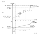
- FIG. 4 is an exemplary view illustrating a method for controlling an inverter according to the present disclosure, where (a) illustrated a feedback of pressure data inputted through the pressure sensor (4) in time, (b) illustrates changes of PID reference in time, and (c) illustrates an output frequency of the controller (11).
- the exemplary embodiment of the present disclosure by FIG. 4 explains a case where a pressure data returned during pre-PID delay is more than a set value (soft fill set value).
- the controller (11) increases a frequency until reaching a pre-PID frequency at the beginning (0 to t1), and maintains the pre-PID frequency at the pre-PID delay time (t1 to t3), which is to allow the pump (3) to reach an operable pressure during pump operation.
- the controller (11) ascertains the feedback of sensor data and when the sensor data reaches the soft fill set value, a normal PID can be started even if the PID delay time is not finished (i.e., the normal PID performance can start at t2 which is earlier than t3).
- the controller (11) performs the PID control in order to increase to the soft fill set value, which is called hereinafter as a 'soft fill PID. That is, the soft fill PID is a PID control used to increase the pressure data returned from the pump (3) to the soft fill set value after end of the pre-PID delay time.
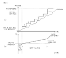
- FIGS. 5 and 6 are other exemplary views illustrating a method for controlling an inverter according to the present disclosure, where (a) illustrates a pressure data that is returned, and (b) illustrates an output frequency of the controller (11).
- a pressure data at the end point of pre-PID is defined as 'soft fill PID reference' when the feedback of pressure data is smaller than the soft fill set value even after the pre-PID has ended.
- the controller (11) according to the present disclosure can control the PID reference to slowly increase the returned pressure data to the soft fill set value, and the PID control at this time is defined as soft fill PID.
- the soft fill PID control according to the present disclosure starts when the pressure data returned after end of the pre-PID fails to reach the soft fill set value.
- the controller (11) performs the PID control using the soft fill PID reference as an initial value. That is, the controller (11) may designate, as a new soft fill PID reference, a reference increased by a predetermined step (A) at each predetermined time (B) on the soft fill PID reference.
- a relevant soft fill PID reference i.e., a value increased as much as A at the soft fill PID reference
- feedback pressure data is less than a set value
- the controller (11) changes to a PID reference to perform a normal PID control.
- FIG. 5 illustrates a case where a feedback pressure data during soft fill PID control has reached a set value
- FIG. 6 illustrates a case where the soft fill PID reference has reached a soft fill set value during soft fill PID control.
- the controller (11) can update the soft fill PID reference by increasing from the initial soft fill PID reference at every period (B) by as much as a predetermined step (A), and can control a normal PID control when the soft fill PID reference reaches a soft fill set value.
- FIG. 7 is a flowchart illustrating a method for controlling an inverter according to an exemplary embodiment of the present disclosure, where the PID reference may be set in advance by a user, and the controller (11) according to the present disclosure performs a soft fill PID, even if the pre-PID has finished while feedback pressure data is less than the soft fill set value.
- the controller (11) can immediately perform a normal PID control (S50) when the feedback pressure data grows greater than the soft fill set value (S15) while performing the pre-PID (S10).
- the pre-PID means the lapse of a pre-PID delay time where an output frequency increases up to a frequency lower limit and when the output frequency reaches the frequency lower limit, the pre-PID frequency is maintained after lapse of a normal acceleration/deceleration time up to the pre-PID delay time, as illustrated in FIGS. 1a and 1b .
- the pre-PID is well known to the skilled in the art such that no more detailed explanation thereto will be made hereinafter.
- the pre-PID is defined as a soft fill set value that is smaller by a predetermined amount than the PID reference.
- the controller (11) sets a value of feedback pressure data when the pre-PID ends as 'initial soft fill PID reference' (S20), and updates to a soft fill PID reference (S25) at a relevant period by increasing an initial soft fill PID reference by a predetermined step (A) when the pre-PID ends.
- a soft fill PID reference of previous period may be increased by a predetermined step (A) to update to a soft fill PID reference (S40), only when a difference between the soft fill PID reference of previous period (because period has lapsed) and feedback pressure data when period lapses is less than a set value (S35).
- a set value S35
- the controller (11) may use the updated soft fill PID reference to perform a PID control (soft fill PID) and output an output frequency.
- a normal PID control may be performed (S55).
- the normal PID control may be performed to output an output frequency capable of controlling the motor (2) (S55).
- the present disclosure can perform the soft fill PID, when the feedback pressure data after pre-PID delay fails to reach the soft fill set value. That is, the pump (3) can be prevented from being damaged through operation without sudden pressure change until the pump (3) reaches a normally operable pressure by update through periodic increase by a predetermined step at an initial soft fill PID reference, and through increase only when a difference between the soft fill PID reference and feedback pressure data is less than a set value.
Landscapes
- Engineering & Computer Science (AREA)
- Mechanical Engineering (AREA)
- General Engineering & Computer Science (AREA)
- Power Engineering (AREA)
- Computer Hardware Design (AREA)
- General Physics & Mathematics (AREA)
- Automation & Control Theory (AREA)
- Physics & Mathematics (AREA)
- Control Of Positive-Displacement Pumps (AREA)
- Inverter Devices (AREA)
- Control Of Ac Motors In General (AREA)
- Feedback Control In General (AREA)
- Control Of Fluid Pressure (AREA)
Description
- The present disclosure relates to a method for controlling an inverter.
- Generally, when a pump is directly started for pump control, chances are that an excessive pressure is instantly applied to a pump pipe to damage the pump or a pipe connecting the pump to a water tank may be damaged.
- In order to solve the aforementioned problem, a normal acceleration/deceleration is performed to a pre-PID (Proportional Integral Derivative) frequency, where a pre-PID delay time (so call 'soft fill time") is maintained. When a feedback relative to a pressure is less than a pre-PID exit set up by a user, a normal PID control is performed after lapse of the pre-PID. When the pressure reaches the pre-PID frequency, the PID control is not performed during maintenance of the pre-PID soft fill time.
-
FIGS. 1a and1b are exemplary views illustrating a conventional inverter control, whereFIG. 1a is an exemplary view illustrating a case where feedback has reached a pre-PID soft fill time value before lapse of the pre-PID soft fill time in the pre-PID frequency, andFIG. 1b illustrates a case where the feedback is less than a pre-PID soft fill value even after maintenance of the pre-PID soft fill time. - Referring to
FIG. 1a , it can be noted that a normal PID is performed when pressure data returned before end of the pre-PID soft fill time in the pre-PID frequency reaches a pre-PID soft fill value. - However, as shown in
FIG.1b , in a case a pressure data returned even after lapse of the pre-PID soft fill time has many differences over the pre-PID soft fill value, PID control burden rate increases when a normal PID starts to suddenly increase a PID output, and as a result, a pump damage by changes in sudden pump pressure cannot be disadvantageously prevented. - Exemplary aspects of the present disclosure are to substantially solve at least the above problems and/or disadvantages and to provide at least the advantages as mentioned below. Thus, the present disclosure is directed to provide a method for controlling inverter configured to prevent a pump from being damaged by sudden changes in pressure inside a pump during pump control. The present disclosure is also directed to provide a method for controlling inverter configured to prevent a pump from being damaged, because there is generated no big difference between a feedback pressure and a normally operable pump pressure set up by a user.
- In one general aspect of the present invention, there is provided a method for controlling an inverter in a system including a pressure sensor configured to detect a pressure of a pump, a motor configured to drive the pump, and an inverter configured to drive the motor, the method comprising:
- setting, as a first reference, a pressure data returned from the pressure sensor when a pre-PID ends;
- updating the first reference by as much as a predetermined step to a second reference;
- determining an output frequency of the inverter by performing a PID control using the second reference; and
- determining an output frequency of the inverter by performing the PID using a third reference set up by the user when the second reference or feedback pressure data is equal to a set value.
- Preferably, but not necessarily, the method may further comprise updating the second reference by as much as a predetermined step to a fourth reference when a difference between the second reference and a pressure data returned from a relevant point is less than a set value after laps of a predetermined period.
- Preferably, but not necessarily, the method may further comprise determining an output frequency of the inverter by performing a PID control using the fourth reference.
- Preferably, but not necessarily, the method may further comprise updating the second reference to a reference of relevant period when a difference between the second reference and a pressure data returned from a relevant point is more than a set value after laps of a predetermined period.
- Preferably, but not necessarily, the method may further comprise determining an output frequency by performing a PID control using the second reference.
- Preferably, but not necessarily, the set value may be less than the third reference.
- According to the exemplary embodiment of the present disclosure, a soft fill PID is performed when a pressure data returned after a pre-PID delay fails to reach a soft fill set value. That is, update is made by periodically increasing an initial soft fill PID reference by a predetermined step only when a difference between a soft fill PID reference and returned pressure data is less than a set value, whereby a pump can be operated without a drastic change in pressure until reaching a normally operable pressure to prevent the pump from being damaged.
-
-
FIGS. 1a and1b are exemplary views illustrating a conventional inverter control. -
FIG. 2 is a block diagram illustrating an inverter system according to the present disclosure. -
FIG. 3 is a detailed block diagram illustrating a controller according to an exemplary embodiment of the present disclosure. -
FIG. 4 is an exemplary view illustrating a method for controlling an inverter according to the present disclosure. -
FIGS. 5 and6 are other exemplary views illustrating a method for controlling an inverter according to the present disclosure. -
FIG. 7 is a flowchart illustrating a method for controlling an inverter according to an exemplary embodiment of the present disclosure. - Various exemplary embodiments will be described more fully hereinafter with reference to the accompanying drawings, in which some exemplary embodiments are shown. The present inventive concept may, however, be embodied in many different forms and should not be construed as limited to the example embodiments set forth herein. Rather, the described aspect is intended to embrace all such alterations, modifications, and variations that fall within the scope and novel idea of the present disclosure.
- Now, exemplary embodiments of the present disclosure will be explained in detail together with the accompanying drawings.
-
FIG. 2 is a block diagram illustrating an inverter system according to the present disclosure. - Referring to
FIG. 2 , the inverter system according to the present disclosure includes an inverter (1) and a motor (2) configured to receive a voltage of predetermined size and frequency from the inverter (1), where a pump (3) connected to the motor (2) is driven by the motor (2). - In general, a pump (3) is a machine configured to introduce liquid through an inlet and discharge the liquid through an outlet, and is driven by the motor (2). The configuration of a pump (3) is irrelevant to the present disclosure such that no more further detailed explanation thereto will be made.
- A pressure sensor (4) is installed at a fluid path connected to the pump (3), and although the pressure sensor (4) is installed at an outlet, for example, an installed position of the pressure sensor (4) is not limited according to the present disclosure. That is, the pressure sensor (4) may be located at various positions. A pressure of the fluid path detected by the pressure sensor (4) may be used as a feedback for controlling an inverter according to the present disclosure.
- Meanwhile, although the present disclosure has described the pressure of fluid path detected by the pressure sensor (4) as a feedback relative to state of the fluid path, the present disclosure is not limited thereto. That is, the present disclosure may use a value indicating a state of fluid path detected by various sensors including a fluid sensor as a feedback.
- The inverter (1) according to the present disclosure may include a controller (11), an input/output unit (12) and a PWM (Pulse Width Modulation) performance unit (13). Although the inverter (1) of the present disclosure may include various elements other than the abovementioned elements, the various elements are irrelevant to the present disclosure and therefore omitted in explanation.
- The input/output unit (12) may receive an output of the pressure sensor (4), converts the received output to a digital data and transmit the converted digital data to the controller (11). To this end, the input/output unit (12) may include an ADC (Analogue-to-Digital Converter). The controller (11) may receive data from the input/output unit (12) to generate an output frequency through PID control, and transmit a relevant output frequency to the PWM performance unit (13).
- When the PWM performance unit (13) performs the PWM using the output frequency received from the controller (11) and provides an output thereof to the motor (2), the motor (2) is driven by the output. The PWM performance using an output frequency is well known to the skilled in the art such that no more detailed explanation will be made thereto.
-
FIG. 3 is a detailed block diagram illustrating a controller according to an exemplary embodiment of the present disclosure. - Referring to
FIG. 3 , the controller (11) may include an error generation unit (11A) and a PID controller (11B). The error generation unit (11A) generates an error of pressure data received from the PID reference and the input/output unit (12) and provides the error to the PID controller (11B), where the PID controller (11B) may output an output frequency of the PWM performance unit (13) by performing the PID control. The PID reference is set up by a user, inputted through an input unit (not shown) and is generally called a "pressure command". Now, operation of the controller (11) will be described with reference to the accompanying drawing. -
FIG. 4 is an exemplary view illustrating a method for controlling an inverter according to the present disclosure, where (a) illustrated a feedback of pressure data inputted through the pressure sensor (4) in time, (b) illustrates changes of PID reference in time, and (c) illustrates an output frequency of the controller (11). The exemplary embodiment of the present disclosure byFIG. 4 explains a case where a pressure data returned during pre-PID delay is more than a set value (soft fill set value). - Referring to
FIG. 4 , the controller (11) increases a frequency until reaching a pre-PID frequency at the beginning (0 to t1), and maintains the pre-PID frequency at the pre-PID delay time (t1 to t3), which is to allow the pump (3) to reach an operable pressure during pump operation. At this time, the controller (11) ascertains the feedback of sensor data and when the sensor data reaches the soft fill set value, a normal PID can be started even if the PID delay time is not finished (i.e., the normal PID performance can start at t2 which is earlier than t3). - Meantime, when the feedback of the pressure data is smaller than the soft fill set value even if the pre-PID delay time has finished, the controller (11) performs the PID control in order to increase to the soft fill set value, which is called hereinafter as a 'soft fill PID. That is, the soft fill PID is a PID control used to increase the pressure data returned from the pump (3) to the soft fill set value after end of the pre-PID delay time.
-
FIGS. 5 and6 are other exemplary views illustrating a method for controlling an inverter according to the present disclosure, where (a) illustrates a pressure data that is returned, and (b) illustrates an output frequency of the controller (11). - In the exemplary embodiment of the present disclosure, a pressure data at the end point of pre-PID is defined as 'soft fill PID reference' when the feedback of pressure data is smaller than the soft fill set value even after the pre-PID has ended. At this time, the controller (11) according to the present disclosure can control the PID reference to slowly increase the returned pressure data to the soft fill set value, and the PID control at this time is defined as soft fill PID. The soft fill PID control according to the present disclosure starts when the pressure data returned after end of the pre-PID fails to reach the soft fill set value.
- The controller (11) performs the PID control using the soft fill PID reference as an initial value. That is, the controller (11) may designate, as a new soft fill PID reference, a reference increased by a predetermined step (A) at each predetermined time (B) on the soft fill PID reference.
- At this time, the controller (11), at lapse of predetermined time (B), ascertains a difference between a relevant soft fill PID reference and an actually returned pressure data, and newly designates a soft fill reference increased by A step for only a value less than a set value. That is, when an initial soft fill reference is designated at t0, a soft fill PID reference increased as much as A is used at t0 up to t1 (i.e., during B). When a difference (C) between a relevant soft fill PID reference (i.e., a value increased as much as A at the soft fill PID reference) and feedback pressure data is less than a set value, a new soft fill PID reference increased as much as A can be designated again at t1.
- When a difference between the PID reference and the feedback data exceeds a set value as in t5 while re-designating a soft fill PID reference at every period as noted above, no further increase as much as A is made at next period, and a soft fill PID reference of relevant period may be used as it is until next period.
- Successively, when a pressure data returned as in t6 reaches a soft fill set value, the controller (11) changes to a PID reference to perform a normal PID control.
- In other words,
FIG. 5 illustrates a case where a feedback pressure data during soft fill PID control has reached a set value, whereasFIG. 6 illustrates a case where the soft fill PID reference has reached a soft fill set value during soft fill PID control. As inFIG. 6 , the controller (11) can update the soft fill PID reference by increasing from the initial soft fill PID reference at every period (B) by as much as a predetermined step (A), and can control a normal PID control when the soft fill PID reference reaches a soft fill set value. -
FIG. 7 is a flowchart illustrating a method for controlling an inverter according to an exemplary embodiment of the present disclosure, where the PID reference may be set in advance by a user, and the controller (11) according to the present disclosure performs a soft fill PID, even if the pre-PID has finished while feedback pressure data is less than the soft fill set value. - Referring to
FIG. 7 , the controller (11) according to the present disclosure can immediately perform a normal PID control (S50) when the feedback pressure data grows greater than the soft fill set value (S15) while performing the pre-PID (S10). At this time, the pre-PID means the lapse of a pre-PID delay time where an output frequency increases up to a frequency lower limit and when the output frequency reaches the frequency lower limit, the pre-PID frequency is maintained after lapse of a normal acceleration/deceleration time up to the pre-PID delay time, as illustrated inFIGS. 1a and1b . The pre-PID is well known to the skilled in the art such that no more detailed explanation thereto will be made hereinafter. - In the method for controlling an inverter according to the present disclosure, the pre-PID is defined as a soft fill set value that is smaller by a predetermined amount than the PID reference.
- Meanwhile, when the feedback pressure data is smaller than a soft fill set value even after the pre-PID performance is finished (S15), the controller (11) sets a value of feedback pressure data when the pre-PID ends as 'initial soft fill PID reference' (S20), and updates to a soft fill PID reference (S25) at a relevant period by increasing an initial soft fill PID reference by a predetermined step (A) when the pre-PID ends.
- Thereafter, when a predetermined period (B) lapses (S30), a soft fill PID reference of previous period may be increased by a predetermined step (A) to update to a soft fill PID reference (S40), only when a difference between the soft fill PID reference of previous period (because period has lapsed) and feedback pressure data when period lapses is less than a set value (S35). As a result of ascertainment at S35, if the difference between the soft fill PID reference of previous period and feedback pressure data of lapsed period is more than a set value, no increase by a predetermined step is made, and the soft fill PID reference of previous period may be updated to a soft fill PID reference of relevant period. The controller (11) may use the updated soft fill PID reference to perform a PID control (soft fill PID) and output an output frequency.
- At this time, when the feedback pressure data and soft fill set value becomes equal (S45), a normal PID control may be performed (S55). Alternatively, even if the soft fill PID reference of relevant period becomes equal to the soft fill set value (S50), the normal PID control may be performed to output an output frequency capable of controlling the motor (2) (S55).
- As apparent from the foregoing, the present disclosure can perform the soft fill PID, when the feedback pressure data after pre-PID delay fails to reach the soft fill set value. That is, the pump (3) can be prevented from being damaged through operation without sudden pressure change until the pump (3) reaches a normally operable pressure by update through periodic increase by a predetermined step at an initial soft fill PID reference, and through increase only when a difference between the soft fill PID reference and feedback pressure data is less than a set value.
- The abovementioned embodiments are intended to be illustrative, and not to limit the scope of the claims. Many alternatives, modifications, and variations will be apparent to those skilled in the art. The features, structures, methods, and other characteristics of the exemplary embodiments described herein may be combined in various ways to obtain additional and/or alternative exemplary embodiments.
Claims (6)
- A method for controlling an inverter in a system including a pressure sensor(4) configured to detect a pressure of a pump(3), a motor configured to drive the pump(3), and an inverter(1) configured to drive the motor(2), the method characterized by:setting, as a first reference, a pressure data returned from the pressure sensor(4) when a pre-PID ends(S20);updating the first reference by as much as a predetermined step to a second reference(S25);determining an output frequency of the inverter(1) by performing a PID control using the second reference(S50); anddetermining an output frequency of the inverter by performing the PID using a third reference set up by the user when the second reference or feedback pressure data is equal to a set value(S45, S55).
- The method of claim 1, further characterized by: updating the second reference by as much as a predetermined step to a fourth reference when a difference between the second reference and a pressure data returned from a relevant point is less than a set value after laps of a predetermined period(S35, S40).
- The method of claim 2, further characterized by: determining an output frequency of the inverter(1) by performing a PID control using the fourth reference.
- The method of any one claim from 1 to 3, further characterized by: updating the second reference to a reference of relevant period when a difference between the second reference and a pressure data returned from a relevant point is more than a set value after laps of a predetermined period.
- The method of claim 4, further characterized by: determining an output frequency by performing a PID control using the second reference.
- The method of any one claim from 1 to 5, characterized in that the set value is less than the third reference.
Applications Claiming Priority (1)
| Application Number | Priority Date | Filing Date | Title |
|---|---|---|---|
| KR1020130168389A KR101529793B1 (en) | 2013-12-31 | 2013-12-31 | Method for controlling inverter |
Publications (3)
| Publication Number | Publication Date |
|---|---|
| EP2890002A2 true EP2890002A2 (en) | 2015-07-01 |
| EP2890002A3 EP2890002A3 (en) | 2015-10-14 |
| EP2890002B1 EP2890002B1 (en) | 2019-02-27 |
Family
ID=51178776
Family Applications (1)
| Application Number | Title | Priority Date | Filing Date |
|---|---|---|---|
| EP14177265.7A Active EP2890002B1 (en) | 2013-12-31 | 2014-07-16 | Procédé de contrôle d'un onduleur |
Country Status (6)
| Country | Link |
|---|---|
| US (1) | US9798296B2 (en) |
| EP (1) | EP2890002B1 (en) |
| JP (1) | JP5960760B2 (en) |
| KR (1) | KR101529793B1 (en) |
| CN (1) | CN104747423B (en) |
| ES (1) | ES2724574T3 (en) |
Families Citing this family (2)
| Publication number | Priority date | Publication date | Assignee | Title |
|---|---|---|---|---|
| GB2589878B (en) * | 2019-12-10 | 2022-01-12 | Spring Europe Ltd | A control system |
| CN114281119B (en) * | 2021-12-23 | 2022-11-04 | 无锡汇田水务科技有限公司 | Water pressure control method, secondary water supply system, electronic device, and storage medium |
Family Cites Families (18)
| Publication number | Priority date | Publication date | Assignee | Title |
|---|---|---|---|---|
| JPH0267478A (en) | 1988-08-31 | 1990-03-07 | Shimadzu Corp | Constant pressure control device for liquid pump |
| JPH0861248A (en) * | 1994-08-12 | 1996-03-08 | Kobe Steel Ltd | Method and device for controlling operation of compressor |
| JPH10159743A (en) | 1996-11-29 | 1998-06-16 | Tokimec Inc | Hydraulic control system |
| US5941690A (en) * | 1996-12-23 | 1999-08-24 | Lin; Yung-Te | Constant pressure variable speed inverter control booster pump system |
| JP2001120432A (en) | 1999-10-25 | 2001-05-08 | Matsushita Electric Ind Co Ltd | Electric water heater |
| US7635253B2 (en) * | 2003-02-05 | 2009-12-22 | Drs Sustainment Systems, Inc. | Digital pressure controller for pump assembly |
| EP1847714B1 (en) | 2006-04-20 | 2016-11-09 | ABB Oy | Frequency converter for motor pump |
| JP4699948B2 (en) | 2006-06-30 | 2011-06-15 | 高周波熱錬株式会社 | Valve control device |
| CN100511068C (en) | 2006-12-21 | 2009-07-08 | 上海联达节能科技有限公司 | Intelligent pressure regulating water supply controlling method |
| KR100887149B1 (en) * | 2008-08-12 | 2009-03-04 | 주식회사 두크 | Inverter booster pump unit with discharge low pressure detection |
| US8135529B2 (en) | 2008-09-23 | 2012-03-13 | Delta Electronics, Inc. | Method for controlling constant-pressure fluid |
| CN201306269Y (en) | 2008-09-24 | 2009-09-09 | 东营市天信纺织有限公司 | Pressure constant device controlled by frequency converter |
| CN201461354U (en) | 2009-06-15 | 2010-05-12 | 上海远动科技有限公司 | Variable frequency regulation closed-loop control system of water pump |
| ATE552423T1 (en) | 2010-02-12 | 2012-04-15 | Allweiler Ag | OPERATIONAL CONTROL DEVICE FOR A DISPLACEMENT PUMP, PUMP SYSTEM AND METHOD FOR OPERATING SAME |
| KR101586856B1 (en) * | 2011-02-15 | 2016-01-20 | (주)우림펌프테크 | Existing pump controller |
| KR101238946B1 (en) * | 2011-03-18 | 2013-03-04 | 엘에스산전 주식회사 | Pump system and operation method thereof |
| DE102011050017A1 (en) * | 2011-04-29 | 2012-10-31 | Allweiler Gmbh | Control means for driving a frequency converter and driving method |
| JP2014231823A (en) | 2013-05-30 | 2014-12-11 | 株式会社荏原製作所 | Pump device |
-
2013
- 2013-12-31 KR KR1020130168389A patent/KR101529793B1/en active Active
-
2014
- 2014-07-10 US US14/328,259 patent/US9798296B2/en active Active
- 2014-07-16 EP EP14177265.7A patent/EP2890002B1/en active Active
- 2014-07-16 ES ES14177265T patent/ES2724574T3/en active Active
- 2014-08-05 JP JP2014159276A patent/JP5960760B2/en active Active
- 2014-10-24 CN CN201410575748.4A patent/CN104747423B/en active Active
Non-Patent Citations (1)
| Title |
|---|
| None |
Also Published As
| Publication number | Publication date |
|---|---|
| EP2890002B1 (en) | 2019-02-27 |
| EP2890002A3 (en) | 2015-10-14 |
| JP5960760B2 (en) | 2016-08-02 |
| CN104747423A (en) | 2015-07-01 |
| KR101529793B1 (en) | 2015-06-17 |
| ES2724574T3 (en) | 2019-09-12 |
| JP2015130146A (en) | 2015-07-16 |
| US20150185711A1 (en) | 2015-07-02 |
| US9798296B2 (en) | 2017-10-24 |
| CN104747423B (en) | 2017-03-29 |
Similar Documents
| Publication | Publication Date | Title |
|---|---|---|
| CN103419782B (en) | Traveling deviation rectifying device, traveling deviation rectifying method and engineering machinery | |
| JP6581626B2 (en) | Water supply equipment | |
| RU2015148490A (en) | SETTING THE WATER PRESSURE INCREASE AND ITS CONTROL METHOD | |
| EP2890002B1 (en) | Procédé de contrôle d'un onduleur | |
| AU2018226492B2 (en) | Power-loss ridethrough system and method | |
| JP6505796B2 (en) | Remote diagnostic operation method for elevator, elevator control device, remote diagnostic system for elevator, and remote diagnostic operation program for elevator | |
| EP1847714B1 (en) | Frequency converter for motor pump | |
| EP3239522B1 (en) | Apparatus for controlling multiple inverters and inverter system including the same | |
| EP4202225A1 (en) | Multi-setting pump with delayed setting switching function | |
| JP6800250B2 (en) | Harmonic suppression device and harmonic suppression system | |
| JP2016217195A (en) | Pump unit, remote control device, and control method of the pump unit | |
| JP5171013B2 (en) | Method and apparatus for controlling pump operation of water supply apparatus | |
| CN104158465A (en) | Motor controlling method, abnormal detecting method for motor belt of washing machine and washing machine | |
| EP3249111B1 (en) | Method for controlling flow rate of hydraulic pump of construction machine | |
| US20220216819A1 (en) | Control unit for closed-loop pressure control | |
| KR20160124287A (en) | Booster pump control method | |
| KR101094988B1 (en) | Half Saturated Proportional Integral Controller | |
| JP7033401B2 (en) | Pump device and control method of pump device | |
| JP6341073B2 (en) | Boiler system | |
| JP2021507173A (en) | Multi-pump system and its operation method | |
| JP7452852B2 (en) | water supply device | |
| JP7245015B2 (en) | Pump device control unit and pump device | |
| JP6834523B2 (en) | Electronic control device | |
| JP2012078068A (en) | Automatic bath device | |
| JP2517804Y2 (en) | Water response control device for turbine generator |
Legal Events
| Date | Code | Title | Description |
|---|---|---|---|
| PUAI | Public reference made under article 153(3) epc to a published international application that has entered the european phase |
Free format text: ORIGINAL CODE: 0009012 |
|
| 17P | Request for examination filed |
Effective date: 20140716 |
|
| AK | Designated contracting states |
Kind code of ref document: A2 Designated state(s): AL AT BE BG CH CY CZ DE DK EE ES FI FR GB GR HR HU IE IS IT LI LT LU LV MC MK MT NL NO PL PT RO RS SE SI SK SM TR |
|
| AX | Request for extension of the european patent |
Extension state: BA ME |
|
| PUAL | Search report despatched |
Free format text: ORIGINAL CODE: 0009013 |
|
| AK | Designated contracting states |
Kind code of ref document: A3 Designated state(s): AL AT BE BG CH CY CZ DE DK EE ES FI FR GB GR HR HU IE IS IT LI LT LU LV MC MK MT NL NO PL PT RO RS SE SI SK SM TR |
|
| AX | Request for extension of the european patent |
Extension state: BA ME |
|
| RIC1 | Information provided on ipc code assigned before grant |
Ipc: H02P 27/06 20060101AFI20150908BHEP Ipc: F04B 49/06 20060101ALI20150908BHEP |
|
| R17P | Request for examination filed (corrected) |
Effective date: 20160411 |
|
| RBV | Designated contracting states (corrected) |
Designated state(s): AL AT BE BG CH CY CZ DE DK EE ES FI FR GB GR HR HU IE IS IT LI LT LU LV MC MK MT NL NO PL PT RO RS SE SI SK SM TR |
|
| RIC1 | Information provided on ipc code assigned before grant |
Ipc: H02P 27/06 20060101AFI20180716BHEP Ipc: F04B 49/06 20060101ALI20180716BHEP |
|
| GRAP | Despatch of communication of intention to grant a patent |
Free format text: ORIGINAL CODE: EPIDOSNIGR1 |
|
| STAA | Information on the status of an ep patent application or granted ep patent |
Free format text: STATUS: GRANT OF PATENT IS INTENDED |
|
| INTG | Intention to grant announced |
Effective date: 20180917 |
|
| GRAS | Grant fee paid |
Free format text: ORIGINAL CODE: EPIDOSNIGR3 |
|
| GRAA | (expected) grant |
Free format text: ORIGINAL CODE: 0009210 |
|
| STAA | Information on the status of an ep patent application or granted ep patent |
Free format text: STATUS: THE PATENT HAS BEEN GRANTED |
|
| AK | Designated contracting states |
Kind code of ref document: B1 Designated state(s): AL AT BE BG CH CY CZ DE DK EE ES FI FR GB GR HR HU IE IS IT LI LT LU LV MC MK MT NL NO PL PT RO RS SE SI SK SM TR |
|
| REG | Reference to a national code |
Ref country code: GB Ref legal event code: FG4D |
|
| REG | Reference to a national code |
Ref country code: CH Ref legal event code: EP |
|
| REG | Reference to a national code |
Ref country code: DE Ref legal event code: R096 Ref document number: 602014041682 Country of ref document: DE |
|
| REG | Reference to a national code |
Ref country code: AT Ref legal event code: REF Ref document number: 1102797 Country of ref document: AT Kind code of ref document: T Effective date: 20190315 |
|
| REG | Reference to a national code |
Ref country code: IE Ref legal event code: FG4D |
|
| REG | Reference to a national code |
Ref country code: NL Ref legal event code: MP Effective date: 20190227 |
|
| REG | Reference to a national code |
Ref country code: LT Ref legal event code: MG4D |
|
| PG25 | Lapsed in a contracting state [announced via postgrant information from national office to epo] |
Ref country code: LT Free format text: LAPSE BECAUSE OF FAILURE TO SUBMIT A TRANSLATION OF THE DESCRIPTION OR TO PAY THE FEE WITHIN THE PRESCRIBED TIME-LIMIT Effective date: 20190227 Ref country code: NL Free format text: LAPSE BECAUSE OF FAILURE TO SUBMIT A TRANSLATION OF THE DESCRIPTION OR TO PAY THE FEE WITHIN THE PRESCRIBED TIME-LIMIT Effective date: 20190227 Ref country code: PT Free format text: LAPSE BECAUSE OF FAILURE TO SUBMIT A TRANSLATION OF THE DESCRIPTION OR TO PAY THE FEE WITHIN THE PRESCRIBED TIME-LIMIT Effective date: 20190627 Ref country code: NO Free format text: LAPSE BECAUSE OF FAILURE TO SUBMIT A TRANSLATION OF THE DESCRIPTION OR TO PAY THE FEE WITHIN THE PRESCRIBED TIME-LIMIT Effective date: 20190527 Ref country code: SE Free format text: LAPSE BECAUSE OF FAILURE TO SUBMIT A TRANSLATION OF THE DESCRIPTION OR TO PAY THE FEE WITHIN THE PRESCRIBED TIME-LIMIT Effective date: 20190227 Ref country code: FI Free format text: LAPSE BECAUSE OF FAILURE TO SUBMIT A TRANSLATION OF THE DESCRIPTION OR TO PAY THE FEE WITHIN THE PRESCRIBED TIME-LIMIT Effective date: 20190227 |
|
| PG25 | Lapsed in a contracting state [announced via postgrant information from national office to epo] |
Ref country code: LV Free format text: LAPSE BECAUSE OF FAILURE TO SUBMIT A TRANSLATION OF THE DESCRIPTION OR TO PAY THE FEE WITHIN THE PRESCRIBED TIME-LIMIT Effective date: 20190227 Ref country code: IS Free format text: LAPSE BECAUSE OF FAILURE TO SUBMIT A TRANSLATION OF THE DESCRIPTION OR TO PAY THE FEE WITHIN THE PRESCRIBED TIME-LIMIT Effective date: 20190627 Ref country code: RS Free format text: LAPSE BECAUSE OF FAILURE TO SUBMIT A TRANSLATION OF THE DESCRIPTION OR TO PAY THE FEE WITHIN THE PRESCRIBED TIME-LIMIT Effective date: 20190227 Ref country code: BG Free format text: LAPSE BECAUSE OF FAILURE TO SUBMIT A TRANSLATION OF THE DESCRIPTION OR TO PAY THE FEE WITHIN THE PRESCRIBED TIME-LIMIT Effective date: 20190527 Ref country code: HR Free format text: LAPSE BECAUSE OF FAILURE TO SUBMIT A TRANSLATION OF THE DESCRIPTION OR TO PAY THE FEE WITHIN THE PRESCRIBED TIME-LIMIT Effective date: 20190227 Ref country code: GR Free format text: LAPSE BECAUSE OF FAILURE TO SUBMIT A TRANSLATION OF THE DESCRIPTION OR TO PAY THE FEE WITHIN THE PRESCRIBED TIME-LIMIT Effective date: 20190528 |
|
| REG | Reference to a national code |
Ref country code: ES Ref legal event code: FG2A Ref document number: 2724574 Country of ref document: ES Kind code of ref document: T3 Effective date: 20190912 |
|
| REG | Reference to a national code |
Ref country code: AT Ref legal event code: MK05 Ref document number: 1102797 Country of ref document: AT Kind code of ref document: T Effective date: 20190227 |
|
| PG25 | Lapsed in a contracting state [announced via postgrant information from national office to epo] |
Ref country code: AL Free format text: LAPSE BECAUSE OF FAILURE TO SUBMIT A TRANSLATION OF THE DESCRIPTION OR TO PAY THE FEE WITHIN THE PRESCRIBED TIME-LIMIT Effective date: 20190227 Ref country code: SK Free format text: LAPSE BECAUSE OF FAILURE TO SUBMIT A TRANSLATION OF THE DESCRIPTION OR TO PAY THE FEE WITHIN THE PRESCRIBED TIME-LIMIT Effective date: 20190227 Ref country code: CZ Free format text: LAPSE BECAUSE OF FAILURE TO SUBMIT A TRANSLATION OF THE DESCRIPTION OR TO PAY THE FEE WITHIN THE PRESCRIBED TIME-LIMIT Effective date: 20190227 Ref country code: DK Free format text: LAPSE BECAUSE OF FAILURE TO SUBMIT A TRANSLATION OF THE DESCRIPTION OR TO PAY THE FEE WITHIN THE PRESCRIBED TIME-LIMIT Effective date: 20190227 Ref country code: RO Free format text: LAPSE BECAUSE OF FAILURE TO SUBMIT A TRANSLATION OF THE DESCRIPTION OR TO PAY THE FEE WITHIN THE PRESCRIBED TIME-LIMIT Effective date: 20190227 Ref country code: EE Free format text: LAPSE BECAUSE OF FAILURE TO SUBMIT A TRANSLATION OF THE DESCRIPTION OR TO PAY THE FEE WITHIN THE PRESCRIBED TIME-LIMIT Effective date: 20190227 |
|
| REG | Reference to a national code |
Ref country code: DE Ref legal event code: R097 Ref document number: 602014041682 Country of ref document: DE |
|
| PG25 | Lapsed in a contracting state [announced via postgrant information from national office to epo] |
Ref country code: PL Free format text: LAPSE BECAUSE OF FAILURE TO SUBMIT A TRANSLATION OF THE DESCRIPTION OR TO PAY THE FEE WITHIN THE PRESCRIBED TIME-LIMIT Effective date: 20190227 Ref country code: SM Free format text: LAPSE BECAUSE OF FAILURE TO SUBMIT A TRANSLATION OF THE DESCRIPTION OR TO PAY THE FEE WITHIN THE PRESCRIBED TIME-LIMIT Effective date: 20190227 |
|
| PG25 | Lapsed in a contracting state [announced via postgrant information from national office to epo] |
Ref country code: AT Free format text: LAPSE BECAUSE OF FAILURE TO SUBMIT A TRANSLATION OF THE DESCRIPTION OR TO PAY THE FEE WITHIN THE PRESCRIBED TIME-LIMIT Effective date: 20190227 |
|
| PLBE | No opposition filed within time limit |
Free format text: ORIGINAL CODE: 0009261 |
|
| STAA | Information on the status of an ep patent application or granted ep patent |
Free format text: STATUS: NO OPPOSITION FILED WITHIN TIME LIMIT |
|
| 26N | No opposition filed |
Effective date: 20191128 |
|
| PG25 | Lapsed in a contracting state [announced via postgrant information from national office to epo] |
Ref country code: MC Free format text: LAPSE BECAUSE OF FAILURE TO SUBMIT A TRANSLATION OF THE DESCRIPTION OR TO PAY THE FEE WITHIN THE PRESCRIBED TIME-LIMIT Effective date: 20190227 Ref country code: SI Free format text: LAPSE BECAUSE OF FAILURE TO SUBMIT A TRANSLATION OF THE DESCRIPTION OR TO PAY THE FEE WITHIN THE PRESCRIBED TIME-LIMIT Effective date: 20190227 |
|
| REG | Reference to a national code |
Ref country code: CH Ref legal event code: PL |
|
| PG25 | Lapsed in a contracting state [announced via postgrant information from national office to epo] |
Ref country code: TR Free format text: LAPSE BECAUSE OF FAILURE TO SUBMIT A TRANSLATION OF THE DESCRIPTION OR TO PAY THE FEE WITHIN THE PRESCRIBED TIME-LIMIT Effective date: 20190227 |
|
| REG | Reference to a national code |
Ref country code: BE Ref legal event code: MM Effective date: 20190731 |
|
| PG25 | Lapsed in a contracting state [announced via postgrant information from national office to epo] |
Ref country code: BE Free format text: LAPSE BECAUSE OF NON-PAYMENT OF DUE FEES Effective date: 20190731 Ref country code: LU Free format text: LAPSE BECAUSE OF NON-PAYMENT OF DUE FEES Effective date: 20190716 Ref country code: LI Free format text: LAPSE BECAUSE OF NON-PAYMENT OF DUE FEES Effective date: 20190731 Ref country code: CH Free format text: LAPSE BECAUSE OF NON-PAYMENT OF DUE FEES Effective date: 20190731 |
|
| PG25 | Lapsed in a contracting state [announced via postgrant information from national office to epo] |
Ref country code: IE Free format text: LAPSE BECAUSE OF NON-PAYMENT OF DUE FEES Effective date: 20190716 |
|
| PG25 | Lapsed in a contracting state [announced via postgrant information from national office to epo] |
Ref country code: CY Free format text: LAPSE BECAUSE OF FAILURE TO SUBMIT A TRANSLATION OF THE DESCRIPTION OR TO PAY THE FEE WITHIN THE PRESCRIBED TIME-LIMIT Effective date: 20190227 |
|
| PG25 | Lapsed in a contracting state [announced via postgrant information from national office to epo] |
Ref country code: MT Free format text: LAPSE BECAUSE OF FAILURE TO SUBMIT A TRANSLATION OF THE DESCRIPTION OR TO PAY THE FEE WITHIN THE PRESCRIBED TIME-LIMIT Effective date: 20190227 Ref country code: HU Free format text: LAPSE BECAUSE OF FAILURE TO SUBMIT A TRANSLATION OF THE DESCRIPTION OR TO PAY THE FEE WITHIN THE PRESCRIBED TIME-LIMIT; INVALID AB INITIO Effective date: 20140716 |
|
| PG25 | Lapsed in a contracting state [announced via postgrant information from national office to epo] |
Ref country code: MK Free format text: LAPSE BECAUSE OF FAILURE TO SUBMIT A TRANSLATION OF THE DESCRIPTION OR TO PAY THE FEE WITHIN THE PRESCRIBED TIME-LIMIT Effective date: 20190227 |
|
| P01 | Opt-out of the competence of the unified patent court (upc) registered |
Effective date: 20230625 |
|
| PGFP | Annual fee paid to national office [announced via postgrant information from national office to epo] |
Ref country code: GB Payment date: 20250610 Year of fee payment: 12 |
|
| PGFP | Annual fee paid to national office [announced via postgrant information from national office to epo] |
Ref country code: FR Payment date: 20250611 Year of fee payment: 12 |
|
| PGFP | Annual fee paid to national office [announced via postgrant information from national office to epo] |
Ref country code: ES Payment date: 20250822 Year of fee payment: 12 |
|
| PGFP | Annual fee paid to national office [announced via postgrant information from national office to epo] |
Ref country code: DE Payment date: 20250609 Year of fee payment: 12 |
|
| PGFP | Annual fee paid to national office [announced via postgrant information from national office to epo] |
Ref country code: IT Payment date: 20250610 Year of fee payment: 12 |